JP6283179B2 - Sheet cutting device - Google Patents
Sheet cutting device Download PDFInfo
- Publication number
- JP6283179B2 JP6283179B2 JP2013152079A JP2013152079A JP6283179B2 JP 6283179 B2 JP6283179 B2 JP 6283179B2 JP 2013152079 A JP2013152079 A JP 2013152079A JP 2013152079 A JP2013152079 A JP 2013152079A JP 6283179 B2 JP6283179 B2 JP 6283179B2
- Authority
- JP
- Japan
- Prior art keywords
- sheet
- fixed blade
- waste
- support portion
- cutting
- Prior art date
- Legal status (The legal status is an assumption and is not a legal conclusion. Google has not performed a legal analysis and makes no representation as to the accuracy of the status listed.)
- Active
Links
- 238000005520 cutting process Methods 0.000 title claims description 184
- 239000002699 waste material Substances 0.000 claims description 151
- 238000007790 scraping Methods 0.000 description 28
- 238000010586 diagram Methods 0.000 description 7
- 239000004020 conductor Substances 0.000 description 4
- 239000010813 municipal solid waste Substances 0.000 description 4
- 230000003068 static effect Effects 0.000 description 4
- 239000000853 adhesive Substances 0.000 description 3
- 230000001070 adhesive effect Effects 0.000 description 3
- 230000008030 elimination Effects 0.000 description 3
- 238000003379 elimination reaction Methods 0.000 description 3
- 230000005484 gravity Effects 0.000 description 3
- 238000012986 modification Methods 0.000 description 3
- 230000004048 modification Effects 0.000 description 3
- 229920000728 polyester Polymers 0.000 description 3
- 229920000122 acrylonitrile butadiene styrene Polymers 0.000 description 2
- 230000000694 effects Effects 0.000 description 2
- 230000005611 electricity Effects 0.000 description 2
- 230000012447 hatching Effects 0.000 description 2
- 229910052751 metal Inorganic materials 0.000 description 2
- 239000002184 metal Substances 0.000 description 2
- 238000011084 recovery Methods 0.000 description 2
- 239000011347 resin Substances 0.000 description 2
- 229920005989 resin Polymers 0.000 description 2
- 240000006829 Ficus sundaica Species 0.000 description 1
- 229910052782 aluminium Inorganic materials 0.000 description 1
- XAGFODPZIPBFFR-UHFFFAOYSA-N aluminium Chemical compound [Al] XAGFODPZIPBFFR-UHFFFAOYSA-N 0.000 description 1
- 238000013459 approach Methods 0.000 description 1
- 239000004744 fabric Substances 0.000 description 1
- NJPPVKZQTLUDBO-UHFFFAOYSA-N novaluron Chemical compound C1=C(Cl)C(OC(F)(F)C(OC(F)(F)F)F)=CC=C1NC(=O)NC(=O)C1=C(F)C=CC=C1F NJPPVKZQTLUDBO-UHFFFAOYSA-N 0.000 description 1
Images


Description
本発明は、シートを断裁するシート断裁装置に関する。 The present invention relates to a sheet cutting apparatus for cutting a sheet.
従来、製本すること等を目的として、シートを断裁するシート断裁装置が用いられている(例えば、特許文献1参照)。従来のシート断裁装置は、断裁対象のシートが載置される台と、台に設けられた帯状の固定刃と、固定刃と協働してシートを断裁する可動刃とを有する。従来のシート断裁装置では、断裁対象のシートが台に載置され、固定刃と可動刃とが協働して断裁対象のシートを断裁する。その際、従来のシート断裁装置は、シートのある一つの端部から別の一つの端部に向かってシートを順に断裁する。断裁によって生じた屑は、落下して屑箱に収められる。 2. Description of the Related Art Conventionally, a sheet cutting apparatus that cuts a sheet has been used for the purpose of bookbinding or the like (for example, see Patent Document 1). A conventional sheet cutting apparatus includes a table on which a sheet to be cut is placed, a band-shaped fixed blade provided on the table, and a movable blade that cuts the sheet in cooperation with the fixed blade. In a conventional sheet cutting apparatus, a sheet to be cut is placed on a table, and the fixed blade and the movable blade cooperate to cut the sheet to be cut. At that time, the conventional sheet cutting apparatus cuts sheets in order from one end of the sheet to another end. The waste generated by the cutting is dropped and stored in the waste bin.
従来のシート断裁装置のように、シートのある一つの端部から別の一つの端部(以下、「別の一つの端部」を「別端部」と記載する場合がある。)に向かってシートを順に断裁する場合、シートのうちのまさに断裁されようとする部位は、シート断裁装置の固定刃と可動刃とによって挟まれて固定刃と可動刃とによって支持される。断裁によって生じた屑は、重力により鉛直下方に垂れ下がる。 Like a conventional sheet cutting apparatus, from one end of a sheet to another end (hereinafter, “another end” may be referred to as “another end”). When the sheets are cut sequentially, the portion of the sheet that is about to be cut is sandwiched between the fixed blade and the movable blade of the sheet cutting apparatus and supported by the fixed blade and the movable blade. The scrap generated by the cutting hangs vertically downward due to gravity.
断裁の終了直前においては、シートの別端部が固定刃と可動刃とによって支持されるので、断裁によって生じた屑はシートから離れることなく別端部の鉛直下方寄りに位置する。断裁が終了すると、屑は別端部の鉛直下方に偏った状態で落下して屑箱に収められる。屑箱において固定刃と平行な辺の長さは上述のある一つの端部から別端部までの長さよりわずかに長いだけであり、屑箱は浅い。すなわち、屑箱は小さい。 Immediately before the end of cutting, the other end portion of the sheet is supported by the fixed blade and the movable blade, so that the waste generated by the cutting is positioned near the vertically lower side of the other end portion without leaving the sheet. When cutting is completed, the waste falls in a state of being biased vertically downward from the other end and is stored in the waste bin. In the trash box, the length of the side parallel to the fixed blade is only slightly longer than the length from one end to the other end described above, and the trash box is shallow. That is, the waste bin is small.
そのため、屑の一部は、別端部の鉛直下方の近傍において屑箱からあふれる。屑箱からあふれた屑は、次の断裁処理時において断裁対象のシートの上に載ったり、断裁対象が重ねられた複数枚のシートである場合に隣り合う2枚のシートの間に挟まれたりして、断裁処理そのものやその後のシートの加工処理等に不具合を生じさせることがある。加えて、上述の通り屑は別端部の鉛直下方に偏った状態で屑箱に収められるので、屑が偏ることなく屑箱に収められる場合に比べて、屑箱に収められた屑の回収を数多く行わなければならない。シートのある一つの端部から別端部に向かってシートを順に断裁しても、断裁によって生じた屑の偏在をより小さくして屑を屑箱に収めるシート断裁装置が提供されることが求められている。 Therefore, a part of the waste overflows from the waste bin in the vicinity of the lower end of the other end vertically. The waste overflowing from the trash box is placed on the sheet to be cut in the next cutting process, or is sandwiched between two adjacent sheets when the cutting target is a plurality of stacked sheets. As a result, problems may occur in the cutting process itself and the subsequent sheet processing. In addition, as described above, the waste is stored in the waste box in a state of being biased vertically below the other end, so that the recovery of the waste stored in the waste box can be performed as compared with the case where the waste is stored in the waste box without being biased. A lot must be done. There is a need to provide a sheet cutting device that reduces the uneven distribution of waste generated by cutting even if the sheet is sequentially cut from one end of the sheet toward another end, and stores the waste in the waste bin. It has been.
本発明は、シートのある一つの端部から別の一つの端部に向かってシートを順に断裁しても、断裁によって生じた屑の偏在をより小さくして屑を屑箱に収めるシート断裁装置を提供することを目的とする。 The present invention relates to a sheet cutting apparatus that reduces the uneven distribution of waste generated by cutting and stores waste in a waste box even if the sheet is sequentially cut from one end to another end of the sheet. The purpose is to provide.
本発明に係るシート断裁装置の一態様は、断裁対象のシートが載置され、略水平な状態で鉛直方向上方に向いた載置面を有する台と、前記台の一端の側から他端の側に延設された帯状の固定刃と、前記固定刃の一端の側から他端の側に順に前記固定刃と近接し、前記固定刃と協働して、前記台の前記載置面に載置された前記シートを前記固定刃の一端の側から他端の側に向かって順に断裁する可動刃と、前記固定刃の前記一端と前記他端との間において、前記固定刃より鉛直方向下方に位置すると共に、前記固定刃より鉛直方向下方に配置される屑箱の底面より鉛直方向上方に位置する支持部と、を有し、前記支持部は、前記台の前記載置面と隣り合う外面における前記固定刃の前記一端及び前記固定刃の前記他端を含む面から直交する方向に突出し、少なくとも一方が前記面に対して傾斜し、前記固定刃と前記可動刃による断裁で生じる屑の一部を一時的に支持する前記固定刃の前記一端に近い側部及び前記固定刃の前記他端に近い側部を備える。 One aspect of the sheet cutting apparatus according to the present invention includes a table on which a sheet to be cut is mounted, a table having a mounting surface facing upward in the vertical direction in a substantially horizontal state, and the other end from one end side of the table . A band-shaped fixed blade extending to the side, and sequentially approaching the fixed blade in order from one end side to the other end side of the fixed blade, and in cooperation with the fixed blade, a movable blade for cutting sequentially the placed said sheet from the side of one end of the fixed blade toward the side of the other end, between said second end and said one end of said fixed blade, vertical than the previous SL fixed blade while positioned in the direction downwards, have a, a supporting portion located vertically above the bottom surface of the waste box to be disposed vertically below the stationary blade, wherein the support portion includes: the base of the mounting surface direction orthogonal to the other end of the one end and the fixed blade of the fixed blade in the adjacent outer surface of including the surface Projects, even without less inclined hand is relative to the previous SL surface, side closer to the one end of the fixed blade for temporarily supporting a part of the debris caused by the cutting by the movable blade and the fixed blade and A side portion close to the other end of the fixed blade is provided .
支持部の側部のうちの固定刃の一端の側の側部は、上記平面と直交していてもよい。又は、支持部の側部のうちの固定刃の一端の側の側部の少なくとも一部は、上記平面と台の載置面との隣り合う平面であって固定刃の一端側に位置する平面側に倒れていてもよい。 The side part of the one side of the fixed blade among the side parts of the support part may be orthogonal to the plane. Alternatively, at least a part of the side portion on the one end side of the fixed blade in the side portion of the support portion is a flat surface adjacent to the flat surface and the mounting surface of the table and located on one end side of the fixed blade. You may have fallen to the surface side .
支持部の側部のうちの固定刃の他端の側の側部は、上記平面と直交していてもよい。又は、支持部の側部のうちの固定刃の他端の側の側部の少なくとも一部は、上記平面と台の載置面との隣り合う平面であって固定刃の一端側に位置する平面側に倒れていてもよい。 The side part on the other end side of the fixed blade among the side parts of the support part may be orthogonal to the plane. Alternatively, at least a part of the side portion on the other end side of the fixed blade among the side portions of the support portion is a plane adjacent to the plane and the mounting surface of the table, and is located on one end side of the fixed blade. it may have fallen on the flat surface side.
支持部はフィルムであって、支持部は、台の載置面が略水平な状態で鉛直方向上方に向いている場合に略水平な状態から鉛直方向下方に姿勢を変える機能と復元する機能とを有してもよい。その場合、支持部の形状は複数の歯からなる櫛状であり、支持部が有する複数の歯のそれぞれは、台の載置面が略水平な状態で鉛直方向上方に向いている場合に鉛直方向に重ならないように配置されてもよい。 Supporting part is a film, the support unit has a function to restore the function of changing the posture in the vertical direction downward from a substantially horizontal state when the pedestal mounting surface is oriented upward in the vertical direction in a substantially horizontal state You may have. In that case, the shape of the support portion is a comb shape composed of a plurality of teeth, and each of the plurality of teeth of the support portion is vertical when the mounting surface of the table is substantially horizontal and faces upward in the vertical direction. You may arrange | position so that it may not overlap in a direction.
シート断裁装置は、支持部が取り付けられる保持部を更に有し、支持部は板状の部材と、取付部とを含み、取付部は、ヒンジとバネとを含み、板状の部材は、台の載置面が略水平な状態で鉛直方向上方に向いている場合に略水平に位置するように取付部によって保持部に取り付けられてもよい。 The sheet cutting device further includes a holding portion to which the support portion is attached. The support portion includes a plate-like member and an attachment portion. The attachment portion includes a hinge and a spring. The plate-like member is a base. The mounting surface may be attached to the holding portion by the attachment portion so as to be positioned substantially horizontally when the mounting surface is directed upward in the vertical direction in a substantially horizontal state.
支持部の上面は、台の載置面が略水平な状態で鉛直方向上方に向いている場合に鉛直方向下方に傾斜していてもよい。 The upper surface of the support portion may be inclined downward in the vertical direction when the mounting surface of the base is directed upward in the vertical direction in a substantially horizontal state.
本発明によれば、シートのある一つの端部から別の一つの端部に向かってシートを順に断裁しても、断裁によって生じた屑の偏在をより小さくして屑を屑箱に収めることができる。 According to the present invention, even when a sheet is sequentially cut from one end of the sheet toward another end, the uneven distribution of the waste generated by the cutting is further reduced and the waste is stored in the waste bin. Can do.
以下に、本発明の実施の形態のシート断裁装置について図面を参照して説明する。本実施の形態のシート断裁装置の構成を説明する前に、本実施の形態のシート断裁装置の動作を簡単に説明する。図1は、本発明の実施の形態のシート断裁装置によって断裁されるシートSの斜視図である。多くの場合、シートSは紙であって、本実施の形態のシート断裁装置は重ねられた複数枚のシートSを断裁する。図1は、複数枚のシートSが重ねられた状況を示している。 A sheet cutting device according to an embodiment of the present invention will be described below with reference to the drawings. Before describing the configuration of the sheet cutting apparatus according to the present embodiment, the operation of the sheet cutting apparatus according to the present embodiment will be briefly described. FIG. 1 is a perspective view of a sheet S cut by the sheet cutting apparatus according to the embodiment of the present invention. In many cases, the sheet S is paper, and the sheet cutting apparatus according to the present embodiment cuts a plurality of stacked sheets S. FIG. 1 shows a situation in which a plurality of sheets S are stacked.
シートSのうちのシート断裁装置によって断裁される部位は、破線で示されている切断線CLである。切断線CLは直線である。本実施の形態のシート断裁装置は、シートSを、シートSのある一つの端部としての切断線CLの一方の端部CL1から、シートSの別の一つの端部としての切断線CLの他方の端部CL2に向かって順に断裁する。シートSにおいて、切断線CLによって区切られている二つの領域のうちの大きい領域Eは、シート断裁装置による断裁の後に製本等に有効に使用される部位である。切断線CLによって区切られている二つの領域のうちの小さい領域Fは、シート断裁装置による断裁の後に屑となる部位である。 A portion of the sheet S that is cut by the sheet cutting device is a cutting line CL indicated by a broken line. The cutting line CL is a straight line. In the sheet cutting apparatus according to the present embodiment, the sheet S is separated from one end CL1 of the cutting line CL as one end of the sheet S from the cutting line CL as another end of the sheet S. Cut in order toward the other end CL2. In the sheet S, a large area E of the two areas separated by the cutting line CL is a part that is effectively used for bookbinding or the like after cutting by the sheet cutting apparatus. A small region F of the two regions separated by the cutting line CL is a part that becomes waste after being cut by the sheet cutting device.
図2は、本発明の実施の形態のシート断裁装置が断裁対象のシートSを断裁している状況を簡単に示す図である。本実施の形態のシート断裁装置は後述の通り可動刃5を有しており、図2では、断裁動作を簡単に説明するために、可動刃5及びシートSのみが示されている。図2には切断線CLの一方の端部CL1は示されていないが、図1を用いて説明した通り、本実施の形態のシート断裁装置は、シートSを、切断線CLの一方の端部CL1から他方の端部CL2に向かって順に断裁する。そのため、図2に示す通り、帯状の屑Wが生成される。屑Wは、落下して後述の屑箱7に収められる。
FIG. 2 is a diagram simply illustrating a situation where the sheet cutting apparatus according to the embodiment of the present invention is cutting the sheet S to be cut. The sheet cutting apparatus according to the present embodiment has a
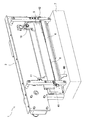
次に、本発明の実施の形態のシート断裁装置の構成を説明する。図3は、本発明の実施の形態におけるシート断裁装置1の斜視図である。図4は、図3に示すシート断裁装置1の正面図である。図5は、図4に示すV−V線におけるシート断裁装置1の断面図である。シート断裁装置1は、画像形成装置の後段に配置される装置であって、製本すること等を目的として、画像形成装置によって処理されたシートSを断裁する。画像形成装置は、図示されていない。 Next, the configuration of the sheet cutting apparatus according to the embodiment of the present invention will be described. FIG. 3 is a perspective view of the sheet cutting apparatus 1 according to the embodiment of the present invention. FIG. 4 is a front view of the sheet cutting apparatus 1 shown in FIG. FIG. 5 is a cross-sectional view of the sheet cutting apparatus 1 taken along the line VV shown in FIG. The sheet cutting apparatus 1 is an apparatus disposed at a subsequent stage of the image forming apparatus, and cuts the sheet S processed by the image forming apparatus for the purpose of bookbinding. The image forming apparatus is not shown.
図3、4及び5に示す通り、シート断裁装置1は、フレーム2と、台3と、固定刃4と、可動刃5と、ガイドプレート6と、屑箱7と、掻き落とし部8と、支持部9とを有する。フレーム2は、台3及び可動刃5が取り付けられるものである。台3は、断裁対象のシートSが載置されるものである。台3は載置面31を有しており、断裁対象のシートSはガイドプレート6による案内により画像形成装置から台3に搬送され、台3の載置面31に載置される。多くの場合、複数枚のシートSが台3の載置面31に載置される。
As shown in FIGS. 3, 4 and 5, the sheet cutting apparatus 1 includes a
固定刃4は、台3の一つの端部に設けられた帯状の刃である。上述の通りシート断裁装置1は画像形成装置の後段に配置される装置であって、固定刃4は、台3の端部のうちの画像形成装置に最も近い端部に設けられている。可動刃5は、固定刃4と協働して、台3の載置面31に載置されたシートSを断裁する板状の刃であって、第1回転部材11及び第2回転部材12によってフレーム2に取り付けられている。
The fixed
フレーム2は、背面側において、第1回転部材11及び第2回転部材12を同期して回転させるためのチェーンを有している。フレーム2は、チェーンを回転させるモータも有している。チェーンがモータによって回転し、チェーンが回転することによって第1回転部材11及び第2回転部材12が同期して回転し、それにより、板状の可動刃5はある一つの平面上で回転する。
The
具体的には、台3の載置面31が水平な状態で鉛直上方に向いている場合、図2に示すように板状の可動刃5はある一つの垂直面上で回転する。その際、可動刃5は、固定刃4の一端41の側から他端42の側に順に固定刃4と近接し、固定刃4と協働して、台3の載置面31に載置されたシートSを、シートSのある一つの端部から別の一つの端部に向かって順に断裁する。更に言うと、台3の載置面31が水平な状態で鉛直上方に向いている場合、可動刃5は固定刃4に近づく状況において鉛直上方から鉛直下方に動きながらシートSを断裁する。なお、固定刃4の一端41は図3、4及び5には明確に示されていないが、上述の通り固定刃4は台3の一つの端部に設けられた帯状の刃であって、固定刃4の他端42が図3及び4において明確に示されているので、固定刃4の一端41を容易に理解することができる。板状の可動刃5は、幅が固定刃4の一端41に近いほど広く、固定刃4の他端42に近いほど狭い台形状の刃である。
Specifically, when the mounting
ガイドプレート6は、断裁対象のシートSを台3の載置面31に案内するものである。上述の通り、シート断裁装置1は画像形成装置の後段に配置されている。そのため、ガイドプレート6は、画像形成装置によって処理されたシートSを製本すること等を目的として断裁するために、画像形成装置によって処理されたシートSを台3の載置面31に案内する。ガイドプレート6は、台3の載置面31に載置された断裁対象のシートSのうちの台3からはみ出た部位を補助的に支持する補助部としても機能する。
The
ガイドプレート6のうちの断裁対象のシートSを台3の載置面31に案内する面(以下、「ガイド面」と記載する。)61は、シートSを台3の載置面31に案内する場合、載置面31を含む平面内に位置する。シートSが固定刃4と可動刃5とによって断裁される場合、上述の通り可動刃5は鉛直上方から鉛直下方に動きながらシートSを断裁する。そのため、シートSが断裁される場合、ガイド面61は可動刃5と接触しないように、可動刃5の動きと連動して鉛直下方に倒れる。
A
屑箱7は、台3の載置面31が水平な状態で鉛直上方に向いている場合に固定刃4より鉛直下方となる位置に配置されている。更に言うと、屑箱7は、上述の場合にガイドプレート6の鉛直下方に配置されている。屑箱7は、固定刃4と可動刃5とによる断裁によって生じて落下してくるシートSの帯状の屑Wが収められる直方体状の箱である。屑箱7には、上述の場合において鉛直上方に位置する開口が形成されており、屑Wは開口から屑箱7の内部に収められる。屑箱7において固定刃4と平行な辺の長さは、シートSにおける切断線CLの長さよりわずかに長いだけである。屑箱7の深さは、例えば切断線CLの3分1程度であって浅い。つまり、屑箱7は小さい。
The
掻き落とし部8は、可動刃5の固定刃4と接触しない側の面を含む面から台3の外側の向きに突出するように設けられており、可動刃5の動きと連動して動く。台3の外側の向きとは、台3の内側から外側への向きを意味する。より具体的には、掻き落とし部8の形状は板状であって、掻き落とし部8は、可動刃5と直交した状態が維持するように、可動刃5に固定された状態で設けられている。
The scraping
更に言うと、掻き落とし部8は、導電性を有する材料によって形成されたブラシである。掻き落とし部8は、台3の載置面31が水平な状態で鉛直上方に向いている場合、鉛直上方から鉛直下方に動き、固定刃4と可動刃5とによる断裁によって生じてガイドプレート6のガイド面61に付着したシートSのうちの帯状の屑Wを掻き落とす。なお、掻き落とし部8は、ガイドプレート6が断裁対象のシートSを台3の載置面31に案内する場合にシートSに接触しない位置に設けられている。
Furthermore, the scraping
支持部9は、固定刃4の一端41と他端42との間において、台3の載置面31が水平な状態で鉛直上方に向いている場合に固定刃4より鉛直下方に位置すると共に、固定刃4より鉛直下方に配置される屑箱7の最上部より鉛直上方に位置している。具体的には、支持部9は、台3の載置面31が水平な状態で鉛直上方に向いている場合にフレーム2の底面となる部位に設けられている。フレーム2の底面は、屑箱7の最上部より鉛直上方に位置している。加えて、支持部9は、台3の載置面31とは異なる外面のうちの固定刃4の一端41及び他端42を含む平面から台3の外側に突出するように設けられている。台3の外側に突出するとは、台3の内側から外側への向きに突出することを意味する。
The
図6は、図3に示すシート断裁装置1の支持部9の平面図である。支持部9はフィルムである。支持部9は例えばポリエステルによって形成されている。支持部9の形状は櫛状であり、図3、4及び6に示す通り、支持部9は複数の歯91,92,93を有している。複数の歯91,92,93は、台3の載置面31とは異なる外面のうちの固定刃4の一端41及び他端42を含む平面から台3の外側に突出するように設けられている。加えて、複数の歯91,92,93のそれぞれは、台3の載置面31が水平な状態で鉛直上方に向いている場合に鉛直方向に重ならないように設けられている。図6は、その場合において支持部9を鉛直上方から鉛直下方の向きに見た状態を示している。すなわち、図6は支持部9の上面図である。
FIG. 6 is a plan view of the
さらに、複数の歯91,92,93は、台3の載置面31が水平な状態で鉛直上方に向いている場合に水平な状態から鉛直下方に姿勢を変える機能と復元する機能とを有する。支持部9は固定部94を有しており、複数の歯91,92,93は固定部94から突出するように設けられている。固定部94は、フレーム2の底面に貼り付けられている。固定部94は、例えば接着剤によってフレーム2の底面に貼り付けられている。固定部94がフレーム2の底面に貼り付けられることにより、支持部9はフレーム2に取り付けられている。なお、固定部94は、ネジ等によりフレーム2の底面に取り付けられてもよい。
Further, the plurality of
図4及び6に示す通り、支持部9の側部のうちの固定刃4の一端41の側の側部は、すなわち、支持部9の歯91は、台3の載置面31とは異なる外面のうちの固定刃4の一端41及び他端42を含む平面と直交している。支持部9の側部のうちの固定刃4の他端42の側の側部も、すなわち、支持部9の歯93も、上述の平面と直交している。図2を用いて説明した通り固定刃4と可動刃5とによる断裁によって帯状の屑Wが生じ、屑Wは落下する。支持部9は、落下してくる帯状の屑Wの一部を一時的に支持する。
As shown in FIGS. 4 and 6, the side portion of the
次に、シートSを断裁した場合に生じる屑Wが落下して屑箱7に収められる状況等を説明する。図1及び2を用いて説明したように、シート断裁装置1は、重ねられた複数のシートSを、切断線CLの一方の端部CL1から他方の端部CL2に向かって順に断裁する。そのため、帯状の屑Wが生成される。屑Wは、ガイドプレート6のガイド面61に静電気等によって付着する場合がある。図7は、断裁対象のシートSが本発明の実施の形態におけるシート断裁装置1によって断裁された場合に屑Wがシート断裁装置1のガイドプレート6のガイド面61に付着している状況を示す図である。
Next, the situation etc. where the waste W generated when the sheet S is cut and fallen into the
更に言うと、図7は、シートSが断裁され、可動刃5が鉛直上方から鉛直下方に動くのに連動してガイドプレート6のガイド面61が鉛直下方に倒れようとしている状況を示している。本実施の形態のシート断裁装置1は、掻き落とし部8を有する。上述の通り、掻き落とし部8は可動刃5に設けられている。そのため、シートSの断裁処理が行われる場合、可動刃5が鉛直上方から鉛直下方に動くので、掻き落とし部8も鉛直上方から鉛直下方に動く。
Furthermore, FIG. 7 shows a situation in which the sheet S is cut and the
掻き落とし部8は、シートSの断裁処理が行われる場合に鉛直上方から鉛直下方に動くので、図8に示すように、ガイドプレート6のガイド面61に付着した屑Wを掻き落とす。図8は、本実施の形態のシート断裁装置1の掻き落とし部8によってガイドプレート6のガイド面61に付着した屑Wが掻き落とされている状況を説明するための図である。すなわち、図8に示すように、本実施の形態のシート断裁装置1を用いれば、ガイドプレート6に付着した屑Wを取り除くことができる。
The
上述の通り、掻き落とし部8は、導電性を有する材料によって形成されているので、帯電した屑Wに対して除電を行うことができる。そのため、掻き落とし部8は、ガイド面61に付着した屑Wをより容易に掻き落とすことができる。加えて、掻き落とし部8は、ブラシであるのでガイド面61に付着した屑Wをこすることができる。そのため、掻き落とし部8は、ガイド面61に付着した屑Wをより容易に掻き落とすことができる。なお、掻き落とし部8は、ガイドプレート6が断裁対象のシートSを台3の載置面31に案内する場合にシートSに接触しない位置に設けられている。そのため、掻き落とし部8により断裁対象のシートSを損傷する可能性を低くすることができる。
As described above, the scraping
次に、シートSを断裁した場合に生じる屑Wが落下して屑箱7に収められる状況を説明する。図1及び2を用いて説明したように、シート断裁装置1による断裁により、帯状の屑Wが生成される。従来のシート断裁装置は、本実施の形態のシート断裁装置1が有する支持部9を有していない点で本実施の形態のシート断裁装置1と異なるが、従来のシート断裁装置も本実施の形態のシート断裁装置1と同様にシートSを断裁し、それにより帯状の屑Wが生成される。
Next, the situation where the waste W generated when the sheet S is cut and dropped and stored in the
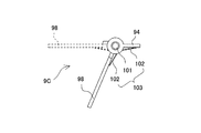
図9A、9B及び9Cを用いて、従来のシート断裁装置がシートSを断裁した場合に生じる屑Wが落下して屑箱7に収められる状況を説明する。図9Aは従来のシート断裁装置がシートSを断裁した場合に生じる屑Wが落下して屑箱7に収められる状況を説明するための第1図であり、図9Bは従来のシート断裁装置がシートSを断裁した場合に生じる屑Wが落下して屑箱7に収められる状況を説明するための第2図であり、図9Cは従来のシート断裁装置がシートSを断裁した場合に生じる屑Wが落下して屑箱7に収められる状況を説明するための第3図である。
9A, 9B, and 9C, the situation where the waste W generated when the conventional sheet cutting apparatus cuts the sheet S falls and is stored in the
図9AはシートSの断裁処理の最初の方の状況を示しており、図9Bは断裁処理の終了直前の状況を示しており、図9Cは断裁処理が終了した後の状況を示している。図9A、9B及び9Cは従来のシート断裁装置の正面側を示しており、図9A、9B及び9Cでは、説明を簡単にするために、固定刃4、可動刃5、屑箱7及び屑Wのみが示されている。屑箱7は内部を示すために破線により示されている。断裁により生じた屑Wと、シートSのうちの断裁により屑Wとなる部位とは、斜線により示されている。なお、図9A、9B及び9Cでは、断裁処理をよりわかりやすくするために、可動刃5の動きを誇張して示している。
9A shows the first situation of the sheet S cutting process, FIG. 9B shows the situation immediately before the end of the cutting process, and FIG. 9C shows the situation after the cutting process ends. 9A, 9B, and 9C show the front side of a conventional sheet cutting apparatus. In FIGS. 9A, 9B, and 9C, the fixed
図9A及び9Bに示すように、シートSのうちのまさに断裁されようとする部位は、固定刃4と可動刃5とによって挟まれて固定刃4と可動刃5とによって支持される。断裁によって生じた屑Wは、重力により鉛直下方に垂れ下がる。したがって、図9Bに示すように、断裁の終了直前においては、シートSにおける切断線CLの他方の端部CL2が固定刃4と可動刃5とによって支持されるので、断裁によって生じた屑WはシートSから離れることなく固定刃4の他端42の鉛直下方寄りに位置する。
As shown in FIGS. 9A and 9B, the portion of the sheet S that is about to be cut is sandwiched between the fixed
そのため、図9Cに示すように、断裁が終了すると、屑Wは固定刃4の他端42の鉛直下方に偏った状態で落下して屑箱7に収められる。上述の通り屑箱7は小さいので、屑Wのうちの最後の方に生じた部位は、固定刃4の他端42の鉛直下方の近傍において屑箱7からあふれる。
Therefore, as shown in FIG. 9C, when cutting is finished, the waste W falls in a state of being biased vertically below the
それに対し、本実施の形態のシート断裁装置1は支持部9を有する。図10A、10B及び10Cを用いて、支持部9を有するシート断裁装置1がシートSを断裁した場合に生じる屑Wが落下して屑箱7に収められる状況を説明する。図10Aは本発明の実施の形態のシート断裁装置1がシートSを断裁した場合に生じる屑Wが落下して屑箱7に収められる状況を説明するための第1図であり、図10Bは本発明の実施の形態のシート断裁装置1がシートSを断裁した場合に生じる屑Wが落下して屑箱7に収められる状況を説明するための第2図であり、図10Cは本発明の実施の形態のシート断裁装置1がシートSを断裁した場合に生じる屑Wが落下して屑箱7に収められる状況を説明するための第3図である。
On the other hand, the sheet cutting apparatus 1 according to the present embodiment has a
図10AはシートSの断裁処理の最初の方の状況を示しており、図10Bは断裁処理の終了直前の状況を示しており、図10Cは断裁処理が終了した後の状況を示している。図10A、10B及び10Cは本実施の形態のシート断裁装置1の正面側を示しており、図10A、10B及び10Cでは、説明を簡単にするために、固定刃4、可動刃5、屑箱7、支持部9及び屑Wのみが示されている。屑箱7は内部を示すために破線により示されている。断裁により生じた屑Wと、シートSのうちの断裁により屑Wとなる部位とは、斜線により示されている。なお、図10A、10B及び10Cでは、断裁処理をよりわかりやすくするために、可動刃5の動きを誇張して示している。
10A shows the first situation of the sheet S cutting process, FIG. 10B shows the situation immediately before the end of the cutting process, and FIG. 10C shows the situation after the cutting process ends. 10A, 10B, and 10C show the front side of the sheet cutting apparatus 1 of the present embodiment. In FIGS. 10A, 10B, and 10C, in order to simplify the explanation, the fixed
図10A及び10Bに示すように、シートSのうちのまさに断裁されようとする部位は、固定刃4と可動刃5とによって挟まれて固定刃4と可動刃5とによって支持される。断裁によって生じた屑Wは重力により鉛直下方に垂れ下がるが、本実施の形態のシート断裁装置1は支持部9を有しており、支持部9が、より具体的には支持部9の複数の歯91,92,93が、断裁によって生じて垂れ下がってくる屑Wの一部を一時的に支持する。そのため、図10Bに示すように、断裁の終了直前においても、断裁によって生じた屑Wは固定刃4の他端42の鉛直下方寄りに偏らない。その結果、図10Cに示すように、断裁が終了すると、屑Wは固定刃4の他端42の鉛直下方に偏った状態で落下せず、偏在がより小さい状態で屑箱7に収められる。
As shown in FIGS. 10A and 10B, the portion of the sheet S that is about to be cut is sandwiched between the fixed
更に言うと、上述の通り、支持部9の側部のうちの固定刃4の一端41の側の側部は、すなわち、支持部9の歯91は、台3の載置面31とは異なる外面のうちの固定刃4の一端41及び他端42を含む平面と直交している。その構成により、断裁によって生じて垂れ下がってくる屑Wの一部は、支持部9の複数の歯91,92,93に引っ掛かる可能性が高くなる。そのため、支持部9は、より具体的には複数の歯91,92,93は、断裁によって生じて垂れ下がってくる屑Wの一部を一時的に支持することを容易に行うことができる。
Furthermore, as described above, the side portion of the
また、支持部9の側部のうちの固定刃4の他端42の側の側部も、すなわち、支持部9の歯93も、台3の載置面31とは異なる外面のうちの固定刃4の一端41及び他端42を含む平面と直交している。その構成により、支持部9の複数の歯91,92,93は断裁によって生じて垂れ下がって一時的に支持した屑Wを、断裁の終了時に鉛直下方に滑らせて屑箱7に収めることを容易に行うことができる。
Further, the side portion of the
さらにまた、支持部9の複数の歯91,92,93は、断裁によって生じて垂れ下がってくる屑Wを一時的に支持した場合、屑Wの重さにより、台3の載置面31が水平な状態で鉛直上方に向いている場合に水平な状態から鉛直下方に姿勢を変える。その構成により、支持部9の複数の歯91,92,93は、断裁によって生じて垂れ下がって一時的に支持した屑Wを、断裁の終了時に鉛直下方に滑らせて屑箱7に収めることを容易に行うことができる。なお、支持部9は、フィルムによって形成されているので、屑Wを一時的に支持する場合は屑Wの重さにより水平な状態から鉛直下方に姿勢を変えるが、屑Wが屑箱7に落下した後に復元する。そのため、支持部9が断裁によって生じて垂れ下がってくる屑Wを一時的に支持する機能は維持される。
Furthermore, when the plurality of
上述の通り、本実施の形態のシート断裁装置1は支持部9を有するので、シート断裁装置1を用いれば、シートSのある一つの端部から別の一つの端部に向かってシートSを順に断裁しても、断裁によって生じた屑Wの偏在をより小さくして屑Wを屑箱7に収めることができる。その結果、屑Wが屑箱からあふれることを抑制でき、ひいては後続の断裁処理等において不具合を生じさせにくくすることができる。加えて、屑箱に収められた屑の回収の回数を抑制することができる。
As described above, the sheet cutting apparatus 1 according to the present embodiment includes the
(変形例)
上述した実施の形態のシート断裁装置1における掻き落とし部8は、可動刃5の固定刃4と接触しない側の面に設けられている。しかしながら、掻き落とし部8は、可動刃5の固定刃4と接触しない側の面に設けられていなくてもよい。掻き落とし部8は、可動刃5の固定刃4と接触しない側において、可動刃5の固定刃4と接触しない側の面を含む面から台3の外側の向きに突出するように設けられており、可動刃5が鉛直上方から鉛直下方に動く場合に鉛直上方から鉛直下方に動いてガイドプレート6に付着した屑Wを掻き落とすものであればよい。
(Modification)
The scraping
したがって、掻き落とし部8の形状は板状でなくてもよいし、掻き落とし部8は、可動刃5と直交した状態が維持するように、可動刃5に固定された状態で設けられていなくてもよい。掻き落とし部8は、除電効果を有することが好ましいが、導電性を有する材料によって形成されていなくてもよい。掻き落とし部8は、ブラシではなく布であってもよい。掻き落とし部8は、可動刃5に搖動可能に取り付けられてもよい。掻き落とし部8は、ガイドプレート6が断裁対象のシートSを台3の載置面31に案内する場合にシートSに接触する位置に設けられてもよい。その場合、掻き落とし部8が除電効果を有していれば、台3の載置面31に案内される断裁対象のシートSを除電することができ、ひいては、屑Wがガイドプレート6に付着する可能性を低下させることができる。
Therefore, the shape of the scraping
上述した実施の形態のシート断裁装置1は、櫛状の支持部9を有する。しかしながら、シート断裁装置1は櫛状の支持部9に替えて台形状の支持部9Aを有してもよい。図11は、台形状の支持部9Aの平面図である。台形状の支持部9Aは、フィルムであって、例えばポリエステルによって形成されている。
The sheet cutting apparatus 1 according to the above-described embodiment has a comb-shaped
台形状の支持部9Aは、櫛状の支持部9における歯91,92,93と同様に、断裁によって生じて垂れ下がってくる屑Wの一部を一時的に支持する台形部95を有すると共に、櫛状の支持部9と同様に固定部94を有する。固定部94が接着剤又はネジ等によってフレーム2の底面に取り付けられることにより、台形状の支持部9Aはフレーム2に取り付けられる。台形状の支持部9Aは、台3の載置面31が水平な状態で鉛直上方に向いている場合に水平な状態から鉛直下方に姿勢を変える機能と復元する機能とを有する。
The
図11に示す通り、台形状の支持部9Aの側部のうちの固定刃4の一端41の側の側部96は、台3の載置面31とは異なる外面のうちの固定刃4の一端41及び他端42を含む平面と直交している。台形状の支持部9Aの側部のうちの固定刃4の他端42の側の側部の一部97は、固定刃4の一端41の側に倒れている。より詳細には、台形状の支持部9Aの側部のうちの固定刃4の他端42の側の側部の一部97は、台3の載置面31と直交すると共に台3の載置面31とは異なる外面のうちの固定刃4の一端41及び他端42を含む平面と直交する平面であって固定刃4の一端41を含む平面の側に倒れている。
As shown in FIG. 11, the
又は、シート断裁装置1は、櫛状の支持部9に替えて、一部にL字状の部位を有する支持部9Bを有してもよい。図12は一部にL字状の部位を含む支持部9Bを有するシート断裁装置1の斜視図であり、図13は図12に示すシート断裁装置1の一部にL字状の部位を含む支持部9Bの平面図である。支持部9Bは、板状の部材であって、ABS樹脂等の樹脂によって形成されていて変形しにくい。
Alternatively, the sheet cutting apparatus 1 may include a
一部にL字状の部位を含む支持部9Bは、櫛状の支持部9における歯91,92,93と同様に、断裁によって生じて垂れ下がってくる屑Wの一部を一時的に支持するL字状部98を有すると共に、櫛状の支持部9と同様に固定部94を有する。固定部94が接着剤又はネジ等によってフレーム2の底面に取り付けられることにより、支持部9Bはフレーム2に取り付けられる。支持部9Bがフレーム2の底面に取り付けられた場合、支持部9BのL字状部98は、台3の載置面31が水平な状態で鉛直上方に向いている場合に水平な状態から鉛直下方に傾斜している。例えば、支持部9BのL字状部98は45°鉛直下方に傾斜している。
The
図12及び13に示す通り、支持部9BにおけるL字状部98の側部のうちの固定刃4の一端41の側の側部の一部99は、固定刃4の一端41の側に倒れている。より詳細には、L字状部98の側部のうちの固定刃4の一端41の側の側部の一部99は、折れ曲がった状態で、台3の載置面31と直交すると共に台3の載置面31とは異なる外面のうちの固定刃4の一端41及び他端42を含む平面と直交する平面であって固定刃4の一端41を含む平面の側に倒れている。L字状部98の側部のうちの固定刃4の他端42の側の側部100も、固定刃4の一端41の側に傾斜することにより倒れている。なお、支持部9Bは、金属によって形成された板状の部材であってもよいし、ポリエステルによって形成されたフィルムであってもよい。また、フレーム2が金属によって形成されたものである場合、支持部9Bはフレーム2と一体に形成されてもよい。
As shown in FIGS. 12 and 13, a
又は、シート断裁装置1は、櫛状の支持部9に替えて、一部にL字状の部位を有する第2の支持部9Cを有してもよい。図14は、一部にL字状の部位を含む第2の支持部9Cを有するシート断裁装置1の斜視図である。図15Aは、図14に示すシート断裁装置1の一部にL字状の部位を含む第2の支持部9Cの平面図であり、図15Bは、図14に示すシート断裁装置1の一部にL字状の部位を含む第2の支持部9Cの側面図であり、図15Cは、図14に示すシート断裁装置1の一部にL字状の部位を含む第2の支持部9Cの斜視図である。図15B及び15Cにおいて破線により示されている部位は、後述するL字状部98が実質的に水平に位置している状態を示している。
Alternatively, the sheet cutting apparatus 1 may include a
一部にL字状の部位を有する第2の支持部9Cは、支持部9Bと同様にL字状部98及び固定部94を有する。L字状部98は板状の部材であって、L字状部98及び固定部94は、ABS樹脂等の樹脂によって一体に形成されている。支持部9Cは、ヒンジ101とバネ102とを有する取付部103を更に持つ。図14、15A、15B及び15Cに示す通り、ヒンジ101は固定部94に取り付けられており、バネ102はL字状部98及び固定部94の鉛直下方に取り付けられている。
The
支持部9Bと同様に、固定部94が保持部としてのフレーム2の底面に取り付けられることにより、支持部9Cはフレーム2に取り付けられる。その際、台3の載置面31が水平な状態で鉛直上方に向いている場合にL字状部98が水平に位置し、バネ102がL字状部98の鉛直下方に位置するように、支持部9Cはフレーム2に取り付けられる。
Similarly to the
又は、シート断裁装置1は、櫛状の支持部9に替えて、塊状の支持部9Dを有してもよい。図16は、塊状の支持部9Dの斜視図である。塊状の支持部9Dの上面は、平面であって、台3の載置面31が水平な状態で鉛直上方に向いている場合に鉛直下方に傾斜している。加えて、塊状の支持部9Dの側部のうちの固定刃4の一端41の側の側部の一部104は、固定刃4の一端41の側に倒れている。より詳細には、上記一部104は、折れ曲がった状態で、台3の載置面31と直交すると共に台3の載置面31とは異なる外面のうちの固定刃4の一端41及び他端42を含む平面と直交する平面であって固定刃4の一端41を含む平面の側に倒れている。
Alternatively, the sheet cutting apparatus 1 may include a
上述の通り、支持部9A、9B、9C及び9Dにおいて、固定刃4の一端41の側の側部は台3の載置面31とは異なる外面のうちの固定刃4の一端41及び他端42を含む平面と直交しているか、固定刃4の一端41の側の側部の少なくとも一部は固定刃4の一端41の側に倒れている。その構成により、断裁によって生じて垂れ下がってくる屑Wは支持部9A、9B、9C及び9Dに引っ掛かり易くなる。すなわち、支持部9A、9B、9C及び9Dは、断裁によって生じて垂れ下がってくる屑Wの一部を一時的に支持することを容易に行うことができる。
As described above, in the
また上述した通り、支持部9A、9B、9C及び9Dにおいて、固定刃4の他端42の側の側部は台3の載置面31とは異なる外面のうちの固定刃4の一端41及び他端42を含む平面と直交しているか、固定刃4の他端42の側の側部の少なくとも一部は固定刃4の一端41の側に倒れている。その構成により、支持部9A、9B、9C及び9Dは、断裁によって生じて垂れ下がって一時的に支持した屑Wを、断裁の終了時に鉛直下方に滑らせて屑箱7に収めることを容易に行うことができる。
Further, as described above, in the
更にまた上述した通り、支持部9A及び9Cの一部は、断裁によって生じて垂れ下がってくる屑Wを一時的に支持した際、屑Wの重さにより、台3の載置面31が水平な状態で鉛直上方に向いている場合に水平な状態から鉛直下方に姿勢を変える。支持部9B及び9Dの上面は、鉛直下方に傾斜している。その構成により、支持部9A、9B、9C及び9Dは、断裁によって生じて垂れ下がって一時的に支持した屑Wを、断裁の終了時に鉛直下方に滑らせて屑箱7に収めることを容易に行うことができる。
Furthermore, as described above, when the supporting
なお、支持部9Aはフィルムによって形成されているので、屑Wを一時的に支持する場合は屑Wの重さにより水平な状態から鉛直下方に姿勢を変えるが、屑Wが屑箱7に落下した後に復元する。そのため、支持部9Aが垂れ下がってくる屑Wを一時的に支持する機能は維持される。支持部9Cはバネ102を有しているので、支持部9Cについての屑Wが屑箱7に落下した後に復元する機能は、支持部9及び9Aよりも長期間にわたって維持される。
In addition, since the
支持部は、上述したものに限定されず、例えば棒状のものであってもよい。 A support part is not limited to what was mentioned above, For example, a rod-shaped thing may be sufficient.
上述した実施の形態では、支持部9は、台3の載置面31が水平な状態で鉛直上方に向いている場合に固定刃4より鉛直下方に配置される屑箱7の最上部より鉛直上方に位置している。そのように、支持部は、上述の場合において屑箱7の底面より鉛直上方に位置する。例えば、支持部は屑箱7の内側面に設けられてもよい。
In the embodiment described above, the
支持部は、アルミニウム等の導電性を有する材料により形成されてもよい。その場合、支持部は、断裁によって生じて垂れ下がって一時的に支持した屑Wが帯電していても除電を行うことができ、断裁の終了時に屑Wを屑箱7に収めることを容易に行うことができる。
The support portion may be formed of a conductive material such as aluminum. In that case, the support part can perform static elimination even if the waste W that is caused by cutting and hangs down and is temporarily supported is charged, and easily puts the waste W in the
上述した実施の形態では、可動刃5は板状の刃である。しかしながら、可動刃5は板状の刃でなくてもよい。
In the embodiment described above, the
上述した実施の形態では、シート断裁装置1は画像形成装置の後段に配置される。しかしながら、本実施の形態のシート断裁装置1は画像形成装置の後段に配置されると限定されない。シート断裁装置1は画像形成装置の後段に配置される場合、ガイドプレート6は断裁対象のシートSを台3の載置面31に案内するが、シート断裁装置1は画像形成装置の後段に配置されない場合、ガイドプレート6は用いられなくてもよい。ただし、ガイドプレート6は台3の載置面31に載置された断裁対象のシートSのうちの台3からはみ出た部位を補助的に支持する補助部としても機能するので、シート断裁装置1は画像形成装置の後段に配置されない場合、ガイドプレート6の代替として、台3の載置面31に載置された断裁対象のシートSのうちの台3からはみ出た部位を補助的に支持する補助部が用いられる。
In the above-described embodiment, the sheet cutting apparatus 1 is arranged at the rear stage of the image forming apparatus. However, the sheet cutting apparatus 1 of the present embodiment is not limited as long as it is arranged at the subsequent stage of the image forming apparatus. When the sheet cutting apparatus 1 is arranged at the rear stage of the image forming apparatus, the
本発明は上述の実施の形態に限定されるものではなく、実施の形態は本発明の趣旨に基づき種々の変形が可能であり、変形例を本発明の技術的範囲から排除しない。 The present invention is not limited to the embodiments described above, and various modifications can be made to the embodiments based on the spirit of the present invention, and modifications are not excluded from the technical scope of the present invention.
本発明は、製本時にシートを断裁するシート断裁装置に関するので産業上の利用可能性を有する。 Since the present invention relates to a sheet cutting apparatus that cuts a sheet during bookbinding, it has industrial applicability.
1 シート断裁装置
2 フレーム
3 台
4 固定刃
5 可動刃
6 ガイドプレート
7 屑箱
8 掻き落とし部
9 支持部
91,92,93 歯
31 載置面
41 一端
42 他端
DESCRIPTION OF SYMBOLS 1
Claims (5)
前記台の一端の側から他端の側に延設された帯状の固定刃と、
前記固定刃の前記一端の側から他端の側に順に前記固定刃と近接し、前記固定刃と協働して、前記台の前記載置面に載置された前記シートを前記固定刃の一端の側から他端の側に向かって順に断裁する可動刃と、
前記固定刃の前記一端と前記他端との間において、前記固定刃より鉛直方向下方に位置すると共に、前記固定刃より鉛直方向下方に配置される屑箱の底面より鉛直方向上方に位置する支持部と、を有し、
前記支持部は、
前記台の前記載置面と隣り合う外面における前記固定刃の前記一端及び前記固定刃の前記他端を含む面から直交する方向に突出し、
少なくとも一方が前記面に対して傾斜し、前記固定刃と前記可動刃による断裁で生じる屑の一部を一時的に支持する前記固定刃の前記一端に近い側部及び前記固定刃の前記他端に近い側部を備えている、
ことを特徴とするシート断裁装置。 A table on which a sheet to be cut is placed and has a placing surface facing upward in the vertical direction in a substantially horizontal state;
A band-shaped fixed blade extending from one end side of the table to the other end side ;
Wherein close to the fixed blade in order from the side of the one end of the fixed blade on the side of the other end, the fixed blade and cooperates, the sheet prior Symbol fixed blade mounted on the mounting surface of the base A movable blade that sequentially cuts from one end side to the other end side,
Between the one end and the other end of the fixed blade, a support that is positioned vertically below the fixed blade and vertically above a bottom surface of a waste box disposed below the fixed blade in the vertical direction. and parts, the possess,
The support part is
Projecting in a direction perpendicular to the plane containing the other end of the one end and the fixed blade of the fixed blade on the outer surface adjacent to said platform of the mounting surface,
The side near the one end of the fixed blade and the other end of the fixed blade that at least one is inclined with respect to the surface and temporarily supports a part of the scrap generated by cutting by the fixed blade and the movable blade and a side near portion,
A sheet cutting apparatus characterized by that .
前記支持部は、略水平な状態から鉛直方向下方に姿勢を変える機能と復元する機能とを有する請求項1に記載のシート断裁装置。 The support part is a film,
The sheet cutting device according to claim 1, wherein the support portion has a function of changing a posture from a substantially horizontal state to a vertically downward direction and a function of restoring.
前記支持部が有する複数の歯のそれぞれは、鉛直方向に重ならないように配置されている請求項2に記載のシート断裁装置。 The shape of the support portion is a comb shape composed of a plurality of teeth,
The sheet cutting device according to claim 2, wherein each of the plurality of teeth of the support portion is arranged so as not to overlap in the vertical direction.
前記支持部は、前記固定刃と前記可動刃による断裁で生じる屑の一部を一時的に支持する板状の部材と、
前記保持部に取り付けられ、前記板状部材を略水平に位置させるためのヒンジとバネとを備えた取付部と、
を備えた請求項1に記載のシート断裁装置。 A holding part to which the support part is attached;
The support part is a plate-like member that temporarily supports a part of scrap generated by cutting by the fixed blade and the movable blade;
An attachment portion that is attached to the holding portion and includes a hinge and a spring for positioning the plate-like member substantially horizontally ;
The sheet cutting device according to claim 1, comprising:
Priority Applications (2)
| Application Number | Priority Date | Filing Date | Title |
|---|---|---|---|
| JP2013152079A JP6283179B2 (en) | 2013-07-22 | 2013-07-22 | Sheet cutting device |
| US14/336,314 US10173337B2 (en) | 2013-07-22 | 2014-07-21 | Sheet cutting device |
Applications Claiming Priority (1)
| Application Number | Priority Date | Filing Date | Title |
|---|---|---|---|
| JP2013152079A JP6283179B2 (en) | 2013-07-22 | 2013-07-22 | Sheet cutting device |
Publications (3)
| Publication Number | Publication Date |
|---|---|
| JP2015020260A JP2015020260A (en) | 2015-02-02 |
| JP2015020260A5 JP2015020260A5 (en) | 2016-09-08 |
| JP6283179B2 true JP6283179B2 (en) | 2018-02-21 |
Family
ID=52485186
Family Applications (1)
| Application Number | Title | Priority Date | Filing Date |
|---|---|---|---|
| JP2013152079A Active JP6283179B2 (en) | 2013-07-22 | 2013-07-22 | Sheet cutting device |
Country Status (1)
| Country | Link |
|---|---|
| JP (1) | JP6283179B2 (en) |
Families Citing this family (2)
| Publication number | Priority date | Publication date | Assignee | Title |
|---|---|---|---|---|
| JP6411960B2 (en) | 2015-07-10 | 2018-10-24 | ファナック株式会社 | Processing machine with static eliminator |
| JP6862851B2 (en) * | 2017-01-24 | 2021-04-21 | コニカミノルタ株式会社 | Cutting equipment, post-processing equipment, and image forming system |
Family Cites Families (5)
| Publication number | Priority date | Publication date | Assignee | Title |
|---|---|---|---|---|
| US3841183A (en) * | 1972-07-31 | 1974-10-15 | Intermenua Pty Ltd | Shearing machine |
| JPS56137915U (en) * | 1981-02-20 | 1981-10-19 | ||
| JP4442844B2 (en) * | 2000-10-13 | 2010-03-31 | キヤノン株式会社 | Sheet cutter and image forming apparatus |
| JP4894737B2 (en) * | 2007-11-28 | 2012-03-14 | 富士ゼロックス株式会社 | Paper processing device |
| JP5451153B2 (en) * | 2009-04-10 | 2014-03-26 | 株式会社セーコウ | Paper sheet cutting device and finisher device using the same |
-
2013
- 2013-07-22 JP JP2013152079A patent/JP6283179B2/en active Active
Also Published As
| Publication number | Publication date |
|---|---|
| JP2015020260A (en) | 2015-02-02 |
Similar Documents
| Publication | Publication Date | Title |
|---|---|---|
| US10173337B2 (en) | Sheet cutting device | |
| JP6283178B2 (en) | Sheet cutting device | |
| JP6283179B2 (en) | Sheet cutting device | |
| JP5550621B2 (en) | Method of separating parts and lattice-like residual material during laser cutting of sheet metal panels | |
| US20200214154A1 (en) | Screen protector and method for applying the same | |
| TW201600284A (en) | Dust collecting mechanism for groove machining head and groove machining apparatus | |
| JP6428642B2 (en) | Method for processing brittle plate and apparatus for processing brittle plate | |
| JP6158744B2 (en) | Cutting blade cleaning mechanism of food cutting equipment | |
| CN104122952A (en) | Memory bank pulling-out tool | |
| JP2015020260A5 (en) | ||
| JP5686657B2 (en) | Electrical equipment storage box | |
| CN105259986A (en) | Dust-proof laptop | |
| KR102281904B1 (en) | Foreign matter removal blade on roller surface that improved adhesion | |
| JP2011025022A (en) | Merchandise display apparatus and merchandise display plate | |
| CN218163062U (en) | SMT divides board tool | |
| JP2001088092A (en) | Method and device for removing punched-out waste produced in punching out paper material | |
| CN214592489U (en) | Component for carrying electronic equipment racks and system with multiple racks | |
| JP2012189647A (en) | Opening/closing structure for device, image forming device and peripheral thereof | |
| CN107845602B (en) | Bearing jig | |
| KR102052007B1 (en) | Protective film deburring device for display panel | |
| JP2011157127A (en) | Dunnage | |
| JP4288211B2 (en) | Paper feeder | |
| KR101493801B1 (en) | Scoop with cutter | |
| TW201725077A (en) | Cleaning method for electronic component | |
| JP5557332B2 (en) | Distribution board load name holder mounting structure |
Legal Events
| Date | Code | Title | Description |
|---|---|---|---|
| A521 | Request for written amendment filed |
Free format text: JAPANESE INTERMEDIATE CODE: A523 Effective date: 20160721 |
|
| A621 | Written request for application examination |
Free format text: JAPANESE INTERMEDIATE CODE: A621 Effective date: 20160721 |
|
| RD02 | Notification of acceptance of power of attorney |
Free format text: JAPANESE INTERMEDIATE CODE: A7422 Effective date: 20160721 |
|
| A131 | Notification of reasons for refusal |
Free format text: JAPANESE INTERMEDIATE CODE: A131 Effective date: 20170525 |
|
| A977 | Report on retrieval |
Free format text: JAPANESE INTERMEDIATE CODE: A971007 Effective date: 20170525 |
|
| A711 | Notification of change in applicant |
Free format text: JAPANESE INTERMEDIATE CODE: A711 Effective date: 20170721 |
|
| A601 | Written request for extension of time |
Free format text: JAPANESE INTERMEDIATE CODE: A601 Effective date: 20170724 |
|
| A711 | Notification of change in applicant |
Free format text: JAPANESE INTERMEDIATE CODE: A712 Effective date: 20170721 |
|
| A521 | Request for written amendment filed |
Free format text: JAPANESE INTERMEDIATE CODE: A523 Effective date: 20170914 |
|
| A131 | Notification of reasons for refusal |
Free format text: JAPANESE INTERMEDIATE CODE: A131 Effective date: 20170929 |
|
| A521 | Request for written amendment filed |
Free format text: JAPANESE INTERMEDIATE CODE: A523 Effective date: 20171122 |
|
| TRDD | Decision of grant or rejection written | ||
| A01 | Written decision to grant a patent or to grant a registration (utility model) |
Free format text: JAPANESE INTERMEDIATE CODE: A01 Effective date: 20180111 |
|
| A61 | First payment of annual fees (during grant procedure) |
Free format text: JAPANESE INTERMEDIATE CODE: A61 Effective date: 20180126 |
|
| R150 | Certificate of patent or registration of utility model |
Ref document number: 6283179 Country of ref document: JP Free format text: JAPANESE INTERMEDIATE CODE: R150 |
|
| R250 | Receipt of annual fees |
Free format text: JAPANESE INTERMEDIATE CODE: R250 |
|
| R250 | Receipt of annual fees |
Free format text: JAPANESE INTERMEDIATE CODE: R250 |
|
| R250 | Receipt of annual fees |
Free format text: JAPANESE INTERMEDIATE CODE: R250 |
|
| R250 | Receipt of annual fees |
Free format text: JAPANESE INTERMEDIATE CODE: R250 |