JP4440657B2 - Punching tool with reusable neutral component unit - Google Patents
Punching tool with reusable neutral component unit Download PDFInfo
- Publication number
- JP4440657B2 JP4440657B2 JP2004006090A JP2004006090A JP4440657B2 JP 4440657 B2 JP4440657 B2 JP 4440657B2 JP 2004006090 A JP2004006090 A JP 2004006090A JP 2004006090 A JP2004006090 A JP 2004006090A JP 4440657 B2 JP4440657 B2 JP 4440657B2
- Authority
- JP
- Japan
- Prior art keywords
- tool
- punching
- plate
- base plate
- lower tool
- Prior art date
- Legal status (The legal status is an assumption and is not a legal conclusion. Google has not performed a legal analysis and makes no representation as to the accuracy of the status listed.)
- Expired - Fee Related
Links
Images


Classifications
-
- B—PERFORMING OPERATIONS; TRANSPORTING
- B26—HAND CUTTING TOOLS; CUTTING; SEVERING
- B26F—PERFORATING; PUNCHING; CUTTING-OUT; STAMPING-OUT; SEVERING BY MEANS OTHER THAN CUTTING
- B26F1/00—Perforating; Punching; Cutting-out; Stamping-out; Apparatus therefor
- B26F1/02—Perforating by punching, e.g. with relatively-reciprocating punch and bed
- B26F1/14—Punching tools; Punching dies
-
- B—PERFORMING OPERATIONS; TRANSPORTING
- B21—MECHANICAL METAL-WORKING WITHOUT ESSENTIALLY REMOVING MATERIAL; PUNCHING METAL
- B21D—WORKING OR PROCESSING OF SHEET METAL OR METAL TUBES, RODS OR PROFILES WITHOUT ESSENTIALLY REMOVING MATERIAL; PUNCHING METAL
- B21D37/00—Tools as parts of machines covered by this subclass
- B21D37/10—Die sets; Pillar guides
-
- B—PERFORMING OPERATIONS; TRANSPORTING
- B26—HAND CUTTING TOOLS; CUTTING; SEVERING
- B26D—CUTTING; DETAILS COMMON TO MACHINES FOR PERFORATING, PUNCHING, CUTTING-OUT, STAMPING-OUT OR SEVERING
- B26D7/00—Details of apparatus for cutting, cutting-out, stamping-out, punching, perforating, or severing by means other than cutting
- B26D7/18—Means for removing cut-out material or waste
- B26D7/1845—Means for removing cut-out material or waste by non mechanical means
- B26D7/1863—Means for removing cut-out material or waste by non mechanical means by suction
-
- B—PERFORMING OPERATIONS; TRANSPORTING
- B26—HAND CUTTING TOOLS; CUTTING; SEVERING
- B26D—CUTTING; DETAILS COMMON TO MACHINES FOR PERFORATING, PUNCHING, CUTTING-OUT, STAMPING-OUT OR SEVERING
- B26D7/00—Details of apparatus for cutting, cutting-out, stamping-out, punching, perforating, or severing by means other than cutting
- B26D7/20—Cutting beds
-
- B—PERFORMING OPERATIONS; TRANSPORTING
- B26—HAND CUTTING TOOLS; CUTTING; SEVERING
- B26F—PERFORATING; PUNCHING; CUTTING-OUT; STAMPING-OUT; SEVERING BY MEANS OTHER THAN CUTTING
- B26F1/00—Perforating; Punching; Cutting-out; Stamping-out; Apparatus therefor
- B26F1/02—Perforating by punching, e.g. with relatively-reciprocating punch and bed
- B26F1/04—Perforating by punching, e.g. with relatively-reciprocating punch and bed with selectively-operable punches
-
- B—PERFORMING OPERATIONS; TRANSPORTING
- B28—WORKING CEMENT, CLAY, OR STONE
- B28B—SHAPING CLAY OR OTHER CERAMIC COMPOSITIONS; SHAPING SLAG; SHAPING MIXTURES CONTAINING CEMENTITIOUS MATERIAL, e.g. PLASTER
- B28B11/00—Apparatus or processes for treating or working the shaped or preshaped articles
- B28B11/12—Apparatus or processes for treating or working the shaped or preshaped articles for removing parts of the articles by cutting
-
- H—ELECTRICITY
- H05—ELECTRIC TECHNIQUES NOT OTHERWISE PROVIDED FOR
- H05K—PRINTED CIRCUITS; CASINGS OR CONSTRUCTIONAL DETAILS OF ELECTRIC APPARATUS; MANUFACTURE OF ASSEMBLAGES OF ELECTRICAL COMPONENTS
- H05K3/00—Apparatus or processes for manufacturing printed circuits
- H05K3/0011—Working of insulating substrates or insulating layers
- H05K3/0044—Mechanical working of the substrate, e.g. drilling or punching
- H05K3/005—Punching of holes
-
- B—PERFORMING OPERATIONS; TRANSPORTING
- B26—HAND CUTTING TOOLS; CUTTING; SEVERING
- B26D—CUTTING; DETAILS COMMON TO MACHINES FOR PERFORATING, PUNCHING, CUTTING-OUT, STAMPING-OUT OR SEVERING
- B26D7/00—Details of apparatus for cutting, cutting-out, stamping-out, punching, perforating, or severing by means other than cutting
- B26D2007/0012—Details, accessories or auxiliary or special operations not otherwise provided for
- B26D2007/0031—Details, accessories or auxiliary or special operations not otherwise provided for floating a web during slitting
-
- B—PERFORMING OPERATIONS; TRANSPORTING
- B26—HAND CUTTING TOOLS; CUTTING; SEVERING
- B26F—PERFORATING; PUNCHING; CUTTING-OUT; STAMPING-OUT; SEVERING BY MEANS OTHER THAN CUTTING
- B26F2210/00—Perforating, punching, cutting-out, stamping-out, severing by means other than cutting of specific products
- B26F2210/08—Perforating, punching, cutting-out, stamping-out, severing by means other than cutting of specific products of ceramic green sheets, printed circuit boards and the like
-
- H—ELECTRICITY
- H05—ELECTRIC TECHNIQUES NOT OTHERWISE PROVIDED FOR
- H05K—PRINTED CIRCUITS; CASINGS OR CONSTRUCTIONAL DETAILS OF ELECTRIC APPARATUS; MANUFACTURE OF ASSEMBLAGES OF ELECTRICAL COMPONENTS
- H05K1/00—Printed circuits
- H05K1/02—Details
- H05K1/03—Use of materials for the substrate
- H05K1/0306—Inorganic insulating substrates, e.g. ceramic, glass
-
- Y—GENERAL TAGGING OF NEW TECHNOLOGICAL DEVELOPMENTS; GENERAL TAGGING OF CROSS-SECTIONAL TECHNOLOGIES SPANNING OVER SEVERAL SECTIONS OF THE IPC; TECHNICAL SUBJECTS COVERED BY FORMER USPC CROSS-REFERENCE ART COLLECTIONS [XRACs] AND DIGESTS
- Y10—TECHNICAL SUBJECTS COVERED BY FORMER USPC
- Y10T—TECHNICAL SUBJECTS COVERED BY FORMER US CLASSIFICATION
- Y10T83/00—Cutting
- Y10T83/202—With product handling means
- Y10T83/2092—Means to move, guide, or permit free fall or flight of product
- Y10T83/2209—Guide
- Y10T83/2213—Product-diverting conduit in or from hollow tool
-
- Y—GENERAL TAGGING OF NEW TECHNOLOGICAL DEVELOPMENTS; GENERAL TAGGING OF CROSS-SECTIONAL TECHNOLOGIES SPANNING OVER SEVERAL SECTIONS OF THE IPC; TECHNICAL SUBJECTS COVERED BY FORMER USPC CROSS-REFERENCE ART COLLECTIONS [XRACs] AND DIGESTS
- Y10—TECHNICAL SUBJECTS COVERED BY FORMER USPC
- Y10T—TECHNICAL SUBJECTS COVERED BY FORMER US CLASSIFICATION
- Y10T83/00—Cutting
- Y10T83/748—With work immobilizer
- Y10T83/7487—Means to clamp work
-
- Y—GENERAL TAGGING OF NEW TECHNOLOGICAL DEVELOPMENTS; GENERAL TAGGING OF CROSS-SECTIONAL TECHNOLOGIES SPANNING OVER SEVERAL SECTIONS OF THE IPC; TECHNICAL SUBJECTS COVERED BY FORMER USPC CROSS-REFERENCE ART COLLECTIONS [XRACs] AND DIGESTS
- Y10—TECHNICAL SUBJECTS COVERED BY FORMER USPC
- Y10T—TECHNICAL SUBJECTS COVERED BY FORMER US CLASSIFICATION
- Y10T83/00—Cutting
- Y10T83/869—Means to drive or to guide tool
- Y10T83/8821—With simple rectilinear reciprocating motion only
- Y10T83/8828—Plural tools with same drive means
-
- Y—GENERAL TAGGING OF NEW TECHNOLOGICAL DEVELOPMENTS; GENERAL TAGGING OF CROSS-SECTIONAL TECHNOLOGIES SPANNING OVER SEVERAL SECTIONS OF THE IPC; TECHNICAL SUBJECTS COVERED BY FORMER USPC CROSS-REFERENCE ART COLLECTIONS [XRACs] AND DIGESTS
- Y10—TECHNICAL SUBJECTS COVERED BY FORMER USPC
- Y10T—TECHNICAL SUBJECTS COVERED BY FORMER US CLASSIFICATION
- Y10T83/00—Cutting
- Y10T83/929—Tool or tool with support
- Y10T83/9411—Cutting couple type
- Y10T83/9423—Punching tool
- Y10T83/9428—Shear-type male tool
- Y10T83/943—Multiple punchings
Description
本発明は打抜き工具、特にグリーンシートのための打抜き工具に関する。 The present invention relates to a punching tool, in particular a punching tool for green sheets.
まだ未焼成である面状のセラミック基板(グリーンシート)には、所定のパターンで単数又は複数の構成部分のため又はスルーコンタクトのために孔を打抜くことが必要である。次いでこの基板は電子的な構成部分と導体路とのための保持体として加工される。打抜き工具は前記目的のためにポンチを備えた上工具と切断プレートを備えた下工具とを有している。切断プレートは平らな上面を有し、該上面には打抜こうとする孔が所定の個所に形成されている。この配置によっては再現可能な打抜きグリッドを有する構成部分を製作することができる。グリーンシートの送りに関連して同一の工具を用いて種々の打抜きパターンもしくは構成部分を生ぜしめることができる。切断プレートの下側には空気分配プレートと真空プレートが配置され、前記空気分配プレートと真空プレートは切断プレートを機械的に支持しかつ要求される媒体を供給する。例えば切断プレートの打抜き孔は、打抜き廃棄物(いわゆる打抜き片)を打抜き孔から吹き出すために圧縮空気で負荷されなければならない。付加的に切断プレートには、グリーンシートを空気のクッションの上で案内するために多数の開口が設けられかつ圧縮空気で負荷されるようになっている。これによりグリーンシートの送りが助けられる。前記開口の配置は打抜き開口の配置同様、グリーンシート内に打抜こうとするパターンに関連する。すなわち前記開口の配置は工作物もしくは構成部分に関連する。これに相応して、媒体を切断プレートに供給する真空プレートの構成も工作物に関連する。真空プレートは同様に下工具ベースプレートにより支持されている。この下工具ベースプレートは工作物固有の真空プレートに適合させられている。 It is necessary to punch holes in a planar ceramic substrate (green sheet) that has not yet been fired in a predetermined pattern for one or more components or for through contact. The substrate is then processed as a holder for electronic components and conductor tracks. For this purpose, the punching tool has an upper tool with a punch and a lower tool with a cutting plate. The cutting plate has a flat upper surface, and holes to be punched are formed at predetermined positions on the upper surface. Depending on this arrangement, it is possible to produce a component with a reproducible punching grid. Various punching patterns or components can be produced using the same tool in connection with green sheet feeding. An air distribution plate and a vacuum plate are arranged below the cutting plate, which mechanically supports the cutting plate and supplies the required media. For example, the punching holes of the cutting plate must be loaded with compressed air in order to blow out punching waste (so-called punched pieces) from the punching holes. In addition, the cutting plate is provided with a number of openings and is loaded with compressed air to guide the green sheet over the air cushion. This helps to feed the green sheet. The arrangement of the openings is related to the pattern to be punched into the green sheet, as is the arrangement of the punching openings. That is, the arrangement of the openings is related to the workpiece or component. Correspondingly, the construction of the vacuum plate for supplying the medium to the cutting plate is also related to the workpiece. The vacuum plate is similarly supported by the lower tool base plate. This lower tool base plate is adapted to the workpiece-specific vacuum plate.
機械を1つの工作物もしくは構成部分から別の打抜きグリッドを有する別の工作物に変更する場合には、打抜き工具全体が交換される。新しい打抜きグリッドを有する構成部分を打抜く場合には工具全体があらためて構成される。 When changing the machine from one workpiece or component to another workpiece having another punching grid, the entire punching tool is replaced. When a component having a new punching grid is punched, the entire tool is reconfigured.
本発明の課題は前記打抜き工具の簡易化を計ることである。 An object of the present invention is to simplify the punching tool.
前記課題は、下工具が非工作物固有のもしくは非構成部材固有の下工具ベースプレートと、工作物固有の下工具作用部とに分割されている本発明の打抜き工具によって解決された。種々異なる工作物に適合させるためには下工具作用部だけが交換される。下工具ベースプレートは非工作物固有である。これにより下工具作用部と下工具ベースプレートとの間には非工作物固有の分割又は切断個所が得られる。これは1つの工作物から別の工作物に変換しようとする場合に下工具作用部だけを交換し、場合によっては上工具作用部分を変更又は調節する可能性をもたらす。この場合には打抜き工具の大部分、すなわち下工具ベースプレートと上工具ベースプレートは変えられることなく引続き使用される。 The object has been solved by a punching tool according to the invention in which the lower tool is divided into a non-workpiece-specific or non-component-specific lower tool base plate and a workpiece-specific lower tool working part. In order to adapt to different workpieces, only the lower tool action is exchanged. The lower tool base plate is non-workpiece specific. As a result, a non-workpiece-specific division or cutting point is obtained between the lower tool operating portion and the lower tool base plate. This gives the possibility to change only the lower tool working part when changing from one workpiece to another and possibly to change or adjust the upper tool working part. In this case, most of the punching tools, i.e., the lower tool base plate and the upper tool base plate are used without change.
下工具ベースプレートは例えばプレステーブルの上に配置される。この場合、プレステーブルと下工具ベースプレートとの間にも非工作物固有の分離個所が設けられている。しかし、別の(第2の)下工具側の非工作物固有のもしくは非構成部分固有の分離個所を付加的に設けることによって、種々異なる工作物のシリーズを製作しようとした場合に必要であった技術的な費用を著しく低下させることが可能になった。すなわち構成部分の各タイプに対し固有の打抜き工具を準備する必要はなくなった。適当な下工具作用部と場合によっては上工具作用部を準備するだけで十分である。 The lower tool base plate is disposed on a press table, for example. In this case, a non-workpiece-specific separation portion is also provided between the press table and the lower tool base plate. However, this is necessary when trying to produce different workpiece series by additionally providing separate non-workpiece-specific or non-component-specific separation points on the other (second) lower tool side. Technical costs can be significantly reduced. That is, it is no longer necessary to prepare a unique punching tool for each type of component. It is sufficient to prepare a suitable lower tool action and possibly an upper tool action.
他の重要な利点はそれ自体高価ではあるが固有ではない機能部材、例えば上工具ベースプレートを精密に下工具ベースプレートに対し案内する真線案内装置は、1つだけしか存在する必要はないことである。これは打抜き工具にて、上工具においても下工具においても、工作物に関連しない切断個所が作用部と対応配置された各ベースプレートと間挿されていることだけで達成される。 Another important advantage is that there is only one true line guiding device which is itself expensive but not unique, for example guiding the upper tool base plate precisely with respect to the lower tool base plate. . This is achieved only by the punching tool, in both the upper tool and the lower tool, where cutting points not related to the workpiece are inserted between the base plates arranged in correspondence with the working parts.
切断個所は有利には下工具作用部を越えて側方へ突出しかつ受容面として構成された平らな面によって形成されている。これによって大きさの異なる下工具作用部がベースプレートの上に固定されることができる。この場合、ベースプレートは側方に配置された両方の直線案内装置の間の間隔を橋絡し、しかも当該工具を作動するプレスのプレステーブルへの結合を行なう。 The cutting point is preferably formed by a flat surface projecting laterally beyond the lower tool action and configured as a receiving surface. As a result, lower tool operating portions having different sizes can be fixed on the base plate. In this case, the base plate bridges the distance between the two linear guide devices arranged on the side, and also connects the press operating the tool to the press table.
打抜き工具は下工具作用部を除いて、打抜こうとする固有の工作物とは無関係に製造することができる。これは構造と製作を著しく簡易化する。しかしながら打抜き工具が非工作物固有である限り、打抜き工具がある程度ストックされるように製作することもできる。これにより全体として製造時間が著しく低減することになる。 The punching tool can be manufactured independently of the specific workpiece to be punched, except for the lower tool working part. This greatly simplifies construction and production. However, as long as the punching tool is non-workpiece specific, it can also be made so that the punching tool is stocked to some extent. This significantly reduces the manufacturing time as a whole.
真空プレートは工作物固有の構成部分に数えられる。真空プレートの上面に真空プレートは有利には、その上にある空気分配プレートと切断プレートとのための支持ウエブを有している。支持ウエブの間には打抜き片のための通路が設けられ、この通路は真空プレートに形成された廃棄ホッパに開口している。さらに真空プレートは真空と圧縮空気とのための媒体通路を有している。下側で真空プレートは下工具ベースプレートにより受容されている。ここに形成された切断個所は非工作物固有の切断個所である。種々異なる工作物のためのすべての真空プレートは下側ではほぼ同じ外観を呈している。上側では真空プレートは工作物固有である。つまり真空プレートはそれぞれその上にある空気分配プレートと切断プレートとに適合させられている。この適合は真空プレートの大きさ、支持ウエブの数と位置、真空又は圧縮空気のための上方へ向いた開口の数と位置及び/又は廃棄ホッパの構成に関して成される。 The vacuum plate is counted in the workpiece-specific component. On the upper surface of the vacuum plate, the vacuum plate advantageously has a supporting web for the air distribution plate and the cutting plate on it. Between the support webs there is a passage for the punched piece, which opens into a waste hopper formed in a vacuum plate. Furthermore, the vacuum plate has a medium passage for vacuum and compressed air. On the lower side, the vacuum plate is received by the lower tool base plate. The cutting point formed here is a cutting point unique to the non-workpiece. All the vacuum plates for different workpieces have almost the same appearance on the underside. On the upper side, the vacuum plate is workpiece specific. That is, the vacuum plates are each adapted to the air distribution plate and the cutting plate above them. This adaptation is made with respect to the size of the vacuum plate, the number and position of the support webs, the number and position of the upward openings for vacuum or compressed air and / or the configuration of the waste hopper.
本発明の有利な実施例の詳細は図面、明細書本文又は従属請求項に開示してある。 The details of advantageous embodiments of the invention are disclosed in the drawings, the description or the dependent claims.
図1には上工具2と下工具3とが所属している打抜き工具1が示されている。打抜き工具1は図示されていないプレス機に組込むために設けられている。このプレス機においては下工具3はプレステーブルの上に静止配置されるのに対し、上工具2は上下に移動させられることができる。上工具2は、少なくとも2つの直線案内5,6が所属する直線案内装置4によって精密に支承されている。直線案内5,6は例えばそれぞれ下工具3に不動に支承された鉛直な柱によって形成されている。この柱には、上工具2内で案内ブシュが配属されている。柱は互いに平行にかつ上工具2の運動方向に沿って配置されている。
FIG. 1 shows a
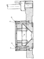
下工具3には下工具ベースプレート7が所属している。この下工具ベースプレート7の上には下工具作用部8が支承されている。下工具ベースプレート7は完全に非工作物固有であるのに対し、下工具作用部8は工作物固有に構成されている。下工具作用部8は図2と図4とに示すように真空プレート9を有し、この真空プレート9はその平らな下面11で下工具ベースプレート7の上面に支えられている。この上面は支持面12として構成されている。支持面12は下工具ベースプレート7の上面全体に亘って、すなわち少なくとも直線案内5,6の間に閉成された領域に亘って延びている。支持面12はすべての考えられる下工具作用部のための統一的な切断個所として役立ち、ひいては打抜き工具1のパターンに関連した部分のために下工具側の境界を形成する。下工具ベースプレート7には通路14,15が形成されており、これらの通路14,15は下工具作用部8に媒体、例えば圧縮空気を供給するために役立つ。下工具ベースプレート7の上面には移行開口が構成され、この移行開口は真空プレート9に形成された圧縮空気供給通路16もしくは真空供給通路17の入口開口と連通している。さらに下工具ベースプレート7には通路18が形成され、この通路18には打抜き片の排出を助ける真空が作用している。真空プレート9は、側方へは壁により取囲まれている内室19を取囲んでいる。圧縮空気供給通路16もしくは真空供給通路17は有利には鉛直方向に前記壁を通って真空プレート9の上面まで延びている。この場合、圧縮空気供給通路16もしくは真空供給通路17は何度も分岐し、したがって複数個所に開口している。真空プレート9の上面には複数のウエブ21が、特に図2と3に示されているように構成されている。ウエブ21は真空プレート9の上側にグリッドを形成する。該グリッドの開口は内室19へ通じている。ウエブ21の配置は工作物に形成しようとする打抜き孔の配置に関連する。図3に示されているように、ウエブ21は真空プレート9の縁と共に平らな面を形成する。この平らな面に圧縮空気供給通路16もしくは真空供給通路17の開口が配置されている。したがって真空プレート9は下面においては工作物固有ではなく、上面においては工作物固有にもしくは構成部分固有に、つまりパターンに関連して構成されている。真空プレート9には空気分配プレート22が配属されている。この空気分配プレート22は上側に圧縮空気通路23を有している。この圧縮空気通路23は浅い溝として構成され、この溝は打抜き開口24へ通じている。さらに空気分配プレート22は圧縮空気のための貫通開口25,26を有していることができる。この貫通開口25,26は真空供給通路17に連通する。シールのためには空気分配プレート22と真空プレート9との間に中間プレート27が図3に示されているように設けられていることができる。中間プレート27はシールとして役立ち、空気分配プレート22もしくは真空プレート9に相応した孔と開口とを備えている。下工具作用部8には真空プレート9と空気分配プレート22と中間プレート27の他に、切断プレート28が所属している。この切断プレート28の基本輪郭は空気分配プレート22の基本輪郭に合致している。切断プレート28には打抜き開口24と貫通開口25,26と取付け開口29とが形成されている。この取付け開口29は図4に示されているように固定ねじ31を受容するために役立つ。別の開口32(図4)は切断プレート28を調整しかつ方向付ける嵌合ピン33を受容するために役立つ。
The lower tool base plate 7 belongs to the
上工具2には図1に示されているように、上工具ベースプレート34が所属しており、この上工具ベースプレート34は上工具作用部35を保持している。この上工具作用部35は互いに平行に延びる多数のポンチ36を有し、各ポンチ36は1つの打抜き開口24と整合している。ポンチ36は交換可能にかつ/又は調節可能に配置されている。
As shown in FIG. 1, the upper
ここまで記述した打抜き工具1の働きは以下の通りである。
The function of the
稼働に際してはグリーンシートが切断プレート28の上で、供給通路17を介して圧縮空気によって生ぜしめられるエアクッションの上に載置される。本来の打抜き過程の前にまず上工具2が下方に向かって移動させられる。その際、切断プレート28と上工具作用部35との間には規定された間隔が生じる。次いで行なわれる打抜き過程でポンチ36はグリーンシートを貫き、それぞれ1つの円筒状の打抜き片を打抜く。この打抜き片は打抜き開口24内へ押込まれる。この場合、ポンチ36の侵入深さは少なくとも、圧縮空気通路23を介し各打抜き開口24に送られた圧縮空気がポンチの端面からの打抜き片の除去を行なうような大きさを有している。したがって打抜き片は下方へ内室19へ侵入し、通路18を介して排出される。
In operation, the green sheet is placed on the cutting
打抜き過程は先きに述べたように連続的に繰返し行なわれる。この場合には一方ではグリーンシートの位置が例えばワングリッド分変えられるか又は新しいグリッドが挿入される。この場合、「グリッド」とは孔パターンの1格子間隔である。 The punching process is continuously repeated as described above. In this case, on the one hand, the position of the green sheet is changed, for example by one grid, or a new grid is inserted. In this case, the “grid” is one lattice interval of the hole pattern.
打抜き工具1を、当該切断プレート28では実現できない構成部分に関連した別の孔パターンを有する別のパターンに合わせて調整する場合には、工具1が更新される。これは下工具作用部8の適当な調節及び/又は上工具作用部35の交換によって達成される。打抜き工具1の残った部分は変えられることなく維持される。
When the
打抜き工具を複数の種々異なるタイプの構成部分のためにストックしておこうとする場合には、適当な上工具作用部と下工具作用部だけを構成部分固有に準備しておくだけで十分である。打抜き工具1の他の部分は変えられる必要はない。
If the punching tool is to be stocked for several different types of components, it is sufficient to prepare only the appropriate upper and lower tool working parts specific to the part. is there. The other parts of the
改善された打抜き工具1は下工具ベースプレート7と下工具作用部8とに分割された下工具3を有している。下工具ベースプレート7は受容面を有し、該受容面には複数の下工具作用部8の統一的な基面が対応している。下工具作用部8と下工具ベースプレート7との間の分離個所はすべての工作物固有の形態がもっぱら下工具作用部8に存在するように配置されている一方、下工具ベースプレート7は加工しようとするすべての工作物に対し変えられる必要がないように構成されている。
The
1 打抜き工具、 2 上工具、 3 下工具、 4 直線案内装置、 5,6 直線案内、 7 下工具ベースプレート、 8 下工具作用部、 9 真空プレート、 11 下面、 12 受容面、 14,15 通路、 16 圧縮空気供給通路、 17 真空供給通路、 18 通路、 19 内室、 20 ウエブ、 22 空気分配プレート、 23 圧縮空気通路、 24 打抜き開口、 25,26 貫通開口、 27 中間プレート、 28 切断プレート、 29 取付け開口、 31 固定ねじ、 32 開口、 33 嵌合ピン、 34 上工具ベースプレート、 35 上工具作用部、 36 ポンチ
DESCRIPTION OF
Claims (7)
打抜き機のテーブルの上に静止的に支承されかつ非工作物固有に構成された下工具ベースプレート(7)を有し、
工作物固有に構成された下工具作用部(8)を有し、
前記下工具ベースプレート(7)に保持された直線案内装置(4)を有し、
上工具ベースプレート(34)を有し、該上工具ベースプレート(34)が前記直線案内装置(4)により下工具ベースプレート(7)に向かってかつ該下工具ベースプレート(7)から遠ざかるように移動可能に支承されかつ非工作物固有に構成されており、
上工具作用部(35)を有し、該上工具作用部(35)が工作物固有に構成されているか又は種々異なる工作物に適合可能であり、
前記下工具作用部(8)が真空プレート(9)と空気分配プレート(22)と中間プレート(27)と切断プレート(28)とを有しており、
前記真空プレート(9)が圧縮空気供給通路(16)と真空供給通路(17)とを有しており、
前記圧縮空気供給通路(16)と前記真空供給通路(17)とが工作物固有であるかもしくは打抜きパターンに関連して構成されていることを特徴とする打抜き工具。 A punching tool (1) for green sheets,
A lower tool base plate (7) stationaryly supported on the table of the punching machine and configured non-workpiece-specifically;
Having a lower tool action part (8) configured unique to the workpiece;
A linear guide device (4) held by the lower tool base plate (7);
Has an upper tool base plate (34), movably to the upper tool base plate (34) moves away from the linear guide unit (4) under the tool base plate (7) to the headed and the lower tool base plate (7) It is supported and is constructed non-workpiece-specific,
Having an upper tool action part (35) , the upper tool action part (35) being configured specifically for the workpiece or adaptable to different workpieces;
The lower tool working portion (8) has a a cutting plate intermediate plate (27) (28) and a vacuum plate (9) and air distribution plate (22),
The has a vacuum supply passage (17) and a vacuum plate (9) is compressed air supply passage (16),
Punching tool, characterized in that the compressed air supply passage (16) the vacuum supply passage and (17) are configured in relation to whether or punching pattern is workpiece-specific.
Applications Claiming Priority (1)
| Application Number | Priority Date | Filing Date | Title |
|---|---|---|---|
| DE2003100818 DE10300818B4 (en) | 2003-01-10 | 2003-01-10 | Punching tool, in particular for green sheets |
Publications (2)
| Publication Number | Publication Date |
|---|---|
| JP2004216551A JP2004216551A (en) | 2004-08-05 |
| JP4440657B2 true JP4440657B2 (en) | 2010-03-24 |
Family
ID=32519856
Family Applications (1)
| Application Number | Title | Priority Date | Filing Date |
|---|---|---|---|
| JP2004006090A Expired - Fee Related JP4440657B2 (en) | 2003-01-10 | 2004-01-13 | Punching tool with reusable neutral component unit |
Country Status (8)
| Country | Link |
|---|---|
| US (1) | US7121178B2 (en) |
| JP (1) | JP4440657B2 (en) |
| KR (1) | KR100618303B1 (en) |
| CN (1) | CN1302899C (en) |
| DE (1) | DE10300818B4 (en) |
| FR (1) | FR2849792B1 (en) |
| IT (1) | ITTO20040005A1 (en) |
| TW (1) | TWI239883B (en) |
Families Citing this family (24)
| Publication number | Priority date | Publication date | Assignee | Title |
|---|---|---|---|---|
| WO2003008159A1 (en) * | 2001-07-17 | 2003-01-30 | Saint-Gobain Isover A/S | A method and an apparatus for producing elements by punching |
| DE102005006782B4 (en) * | 2005-02-14 | 2006-10-19 | Uhlmann Pac-Systeme Gmbh & Co Kg | workstation |
| JP4938471B2 (en) * | 2006-04-13 | 2012-05-23 | アルプス電気株式会社 | Green sheet through-hole processing apparatus and through-hole processing method |
| CN101618555B (en) * | 2008-07-02 | 2011-03-30 | 富葵精密组件(深圳)有限公司 | Punching mould |
| EP2263839A1 (en) * | 2009-06-18 | 2010-12-22 | Amcor Tobacco Packaging Switzerland LLC | Flatbed die-cutting press for cutting shapes in sheets of board material |
| ATE530308T1 (en) * | 2009-07-31 | 2011-11-15 | Groz Beckert Kg | PUNCHING TOOL WITH FLOATING STAMP |
| TWI406609B (en) * | 2009-12-23 | 2013-08-21 | Zhen Ding Technology Co Ltd | Method for manufacturing printed circuit board |
| CN101954417A (en) * | 2010-09-30 | 2011-01-26 | 吴江市华源印铁制罐有限责任公司 | Stamping die device for manufacturing welded ears of convenient barrel |
| CN102555045B (en) * | 2011-10-20 | 2015-09-30 | 蔡灵明 | Burn pre-ceramic wet-method punching machine |
| CN102581877A (en) * | 2012-02-15 | 2012-07-18 | 欧朗科技(苏州)有限公司 | Device for splitting and cutting small-sized circuit board |
| CN102773333A (en) * | 2012-07-20 | 2012-11-14 | 苏州吴中经济开发区搏宇模具加工厂 | Integrator bracket punching die |
| CN103635023B (en) * | 2012-08-27 | 2016-08-24 | 富葵精密组件(深圳)有限公司 | The manufacture method of circuit board |
| DE102012109434A1 (en) * | 2012-10-04 | 2014-04-24 | Groz-Beckert Kg | Method and tool unit for setting a punching gap |
| WO2014133239A1 (en) * | 2013-02-26 | 2014-09-04 | (주)파인테크 | Embossing mold and embossing mold device including same |
| KR101398741B1 (en) | 2013-10-02 | 2014-05-27 | (주)동진이엔지 | Support guiding apparatus of punching board |
| CN104826921B (en) * | 2014-12-31 | 2017-01-04 | 浙江吉利汽车有限公司 | Recycling mold and punching head and reuse method |
| CN104827517A (en) * | 2015-05-05 | 2015-08-12 | 佛山华工祥源环保包装有限公司 | Adsorption-type flash cutting removal device and deflashing process thereof |
| CN107734861B (en) * | 2017-11-23 | 2020-01-24 | 上海御渡半导体科技有限公司 | Use method of multifunctional circuit board punching mechanism |
| CN108215246A (en) * | 2018-03-09 | 2018-06-29 | 湖南航天环宇通信科技股份有限公司 | The forming frock and its application method of porous multiple material product |
| CN108789619A (en) * | 2018-06-26 | 2018-11-13 | 东莞市联洲知识产权运营管理有限公司 | A kind of flexible PCB diel |
| CN109571633A (en) * | 2018-11-03 | 2019-04-05 | 景德镇陶瓷大学 | A kind of mold of paper labels punching |
| CN111571720B (en) * | 2020-05-21 | 2021-10-19 | 丁卫兵 | Light soft material blanking device |
| CN114260966B (en) * | 2021-12-30 | 2023-05-02 | 四川海英电子科技有限公司 | Device and method for forming strip-shaped grooves on high-speed high-density board |
| CN117428076B (en) * | 2023-12-21 | 2024-02-27 | 河南纳澜电器有限公司 | Distribution box metal part processing equipment |
Family Cites Families (17)
| Publication number | Priority date | Publication date | Assignee | Title |
|---|---|---|---|---|
| US2364994A (en) * | 1942-08-03 | 1944-12-12 | Prime Mfg Co | Electrified fence installation |
| US2364011A (en) * | 1943-02-25 | 1944-11-28 | George F Wales | Punching machine |
| US3800643A (en) * | 1972-07-24 | 1974-04-02 | Whitney Corp W | Punch press with improved slug handling system |
| US3797342A (en) * | 1973-03-22 | 1974-03-19 | Ncr | Printed circuit board with plated through holes |
| FR2248666A1 (en) * | 1973-10-22 | 1975-05-16 | Vesnitch Yves | Punching tool for printed circuit boards - using matrix pierced with array of holes of equal diameter |
| US4277994A (en) * | 1977-10-17 | 1981-07-14 | Gargrave Robert J | Matrix element |
| US4872381A (en) * | 1988-07-13 | 1989-10-10 | International Business Machines Corp. | Programmable magnetic repulsion punching apparatus |
| US5303618A (en) * | 1992-09-08 | 1994-04-19 | Norell Ronald A | Via hole punch |
| JP2609214B2 (en) * | 1993-05-12 | 1997-05-14 | ダイワ電機精工株式会社 | Circuit board dividing method and circuit board dividing mold |
| JP2714556B2 (en) * | 1993-05-18 | 1998-02-16 | 北陸電気工業株式会社 | Circuit board dividing mold driving method and circuit board dividing apparatus |
| CN1054788C (en) * | 1995-10-31 | 2000-07-26 | 张云亮 | Stamping die |
| US5836226A (en) * | 1995-12-25 | 1998-11-17 | Ngk Insulators, Ltd. | Apparatus for progressively feeding and machining sheet material |
| US6880441B1 (en) * | 1996-06-06 | 2005-04-19 | International Business Machines Corporation | Precision punch and die design and construction |
| US6003418A (en) * | 1997-07-31 | 1999-12-21 | International Business Machines Corporation | Punched slug removal system |
| DE19751238A1 (en) * | 1997-11-19 | 1999-05-27 | Feintool Int Holding | Press tool for making precision components from strip material, and method for servicing tool |
| US6223636B1 (en) * | 1998-08-03 | 2001-05-01 | International Business Machines Corporation | Low-cost high-density gang punch |
| US6679146B2 (en) * | 2002-01-11 | 2004-01-20 | International Business Machines Corporation | Die set with disposable molybdenum die plate and improved window plate for universal gang-punch tool |
-
2003
- 2003-01-10 DE DE2003100818 patent/DE10300818B4/en not_active Expired - Lifetime
-
2004
- 2004-01-05 FR FR0400017A patent/FR2849792B1/en not_active Expired - Fee Related
- 2004-01-08 KR KR1020040001071A patent/KR100618303B1/en not_active IP Right Cessation
- 2004-01-08 IT ITTO20040005 patent/ITTO20040005A1/en unknown
- 2004-01-09 US US10/753,960 patent/US7121178B2/en not_active Expired - Lifetime
- 2004-01-09 TW TW93100491A patent/TWI239883B/en not_active IP Right Cessation
- 2004-01-09 CN CNB2004100283401A patent/CN1302899C/en not_active Expired - Fee Related
- 2004-01-13 JP JP2004006090A patent/JP4440657B2/en not_active Expired - Fee Related
Also Published As
| Publication number | Publication date |
|---|---|
| TW200424047A (en) | 2004-11-16 |
| TWI239883B (en) | 2005-09-21 |
| FR2849792A1 (en) | 2004-07-16 |
| CN1520974A (en) | 2004-08-18 |
| JP2004216551A (en) | 2004-08-05 |
| US20040163519A1 (en) | 2004-08-26 |
| FR2849792B1 (en) | 2009-05-01 |
| KR100618303B1 (en) | 2006-08-31 |
| DE10300818B4 (en) | 2014-05-15 |
| CN1302899C (en) | 2007-03-07 |
| DE10300818A1 (en) | 2004-07-29 |
| US7121178B2 (en) | 2006-10-17 |
| ITTO20040005A1 (en) | 2004-04-08 |
| KR20040064622A (en) | 2004-07-19 |
Similar Documents
| Publication | Publication Date | Title |
|---|---|---|
| JP4440657B2 (en) | Punching tool with reusable neutral component unit | |
| US6106453A (en) | Method using punching and scoring tool for production of scored punched parts | |
| JP2009066663A (en) | Method and apparatus for precise punching and precise deformation of workpiece | |
| JPH02124295A (en) | Multishaft boring device | |
| JPS63199033A (en) | Modular type punch press device for punching complicated molded form from metallic ribbon or tape | |
| DE60312787D1 (en) | Method and apparatus for separating benefits in a sheet material cutting machine | |
| KR101737743B1 (en) | The plane washer production device which is available the bur remaval | |
| GB2127957A (en) | Removal of debris from template cutting apparatus | |
| CN109789470B (en) | Tool and machine tool for machining plate-shaped workpieces and method | |
| KR101946155B1 (en) | Punching apparatus of paper tray pattern for paper pallet | |
| JP2000343144A (en) | Manufacture of press molding | |
| CN215697268U (en) | Automatic punching machine | |
| US6196775B1 (en) | Apparatus for extracting chips from slots cut into a substrate | |
| KR20170000279A (en) | Fabric punching device | |
| JPH08197158A (en) | Shapes punching machine | |
| KR100840943B1 (en) | The automatic opens and shuts device of plate a cutting machine | |
| CN113414286A (en) | Automatic punching machine | |
| JPH10595A (en) | Waste removal device for die cutting hole for corrugated board | |
| KR100478244B1 (en) | Press apparatus for punching a building pannel | |
| CN207432423U (en) | A kind of notch process equipment | |
| JPH0890096A (en) | Press device | |
| CN210336196U (en) | Paperboard perforating machine capable of simultaneously drilling holes at multiple points | |
| KR200225303Y1 (en) | Insulation vent hole punching machine for generator rotor coil | |
| CN219854986U (en) | Engraving die for thick PC (polycarbonate) | |
| CN210614796U (en) | Side wall back-off side cutting mechanism |
Legal Events
| Date | Code | Title | Description |
|---|---|---|---|
| A621 | Written request for application examination |
Free format text: JAPANESE INTERMEDIATE CODE: A621 Effective date: 20040519 |
|
| A977 | Report on retrieval |
Free format text: JAPANESE INTERMEDIATE CODE: A971007 Effective date: 20070215 |
|
| A131 | Notification of reasons for refusal |
Free format text: JAPANESE INTERMEDIATE CODE: A131 Effective date: 20070223 |
|
| A601 | Written request for extension of time |
Free format text: JAPANESE INTERMEDIATE CODE: A601 Effective date: 20070323 |
|
| A602 | Written permission of extension of time |
Free format text: JAPANESE INTERMEDIATE CODE: A602 Effective date: 20070328 |
|
| A521 | Written amendment |
Free format text: JAPANESE INTERMEDIATE CODE: A523 Effective date: 20070823 |
|
| A131 | Notification of reasons for refusal |
Free format text: JAPANESE INTERMEDIATE CODE: A131 Effective date: 20080319 |
|
| A601 | Written request for extension of time |
Free format text: JAPANESE INTERMEDIATE CODE: A601 Effective date: 20080619 |
|
| A602 | Written permission of extension of time |
Free format text: JAPANESE INTERMEDIATE CODE: A602 Effective date: 20080624 |
|
| A601 | Written request for extension of time |
Free format text: JAPANESE INTERMEDIATE CODE: A601 Effective date: 20080722 |
|
| A602 | Written permission of extension of time |
Free format text: JAPANESE INTERMEDIATE CODE: A602 Effective date: 20080729 |
|
| A601 | Written request for extension of time |
Free format text: JAPANESE INTERMEDIATE CODE: A601 Effective date: 20080819 |
|
| A602 | Written permission of extension of time |
Free format text: JAPANESE INTERMEDIATE CODE: A602 Effective date: 20080822 |
|
| A521 | Written amendment |
Free format text: JAPANESE INTERMEDIATE CODE: A523 Effective date: 20080919 |
|
| A131 | Notification of reasons for refusal |
Free format text: JAPANESE INTERMEDIATE CODE: A131 Effective date: 20090318 |
|
| A601 | Written request for extension of time |
Free format text: JAPANESE INTERMEDIATE CODE: A601 Effective date: 20090618 |
|
| A602 | Written permission of extension of time |
Free format text: JAPANESE INTERMEDIATE CODE: A602 Effective date: 20090623 |
|
| A601 | Written request for extension of time |
Free format text: JAPANESE INTERMEDIATE CODE: A601 Effective date: 20090721 |
|
| A602 | Written permission of extension of time |
Free format text: JAPANESE INTERMEDIATE CODE: A602 Effective date: 20090724 |
|
| A601 | Written request for extension of time |
Free format text: JAPANESE INTERMEDIATE CODE: A601 Effective date: 20090818 |
|
| A602 | Written permission of extension of time |
Free format text: JAPANESE INTERMEDIATE CODE: A602 Effective date: 20090821 |
|
| A521 | Written amendment |
Free format text: JAPANESE INTERMEDIATE CODE: A523 Effective date: 20090911 |
|
| TRDD | Decision of grant or rejection written | ||
| A01 | Written decision to grant a patent or to grant a registration (utility model) |
Free format text: JAPANESE INTERMEDIATE CODE: A01 Effective date: 20091218 |
|
| A01 | Written decision to grant a patent or to grant a registration (utility model) |
Free format text: JAPANESE INTERMEDIATE CODE: A01 |
|
| A61 | First payment of annual fees (during grant procedure) |
Free format text: JAPANESE INTERMEDIATE CODE: A61 Effective date: 20100107 |
|
| FPAY | Renewal fee payment (event date is renewal date of database) |
Free format text: PAYMENT UNTIL: 20130115 Year of fee payment: 3 |
|
| R150 | Certificate of patent or registration of utility model |
Free format text: JAPANESE INTERMEDIATE CODE: R150 |
|
| R250 | Receipt of annual fees |
Free format text: JAPANESE INTERMEDIATE CODE: R250 |
|
| R250 | Receipt of annual fees |
Free format text: JAPANESE INTERMEDIATE CODE: R250 |
|
| R250 | Receipt of annual fees |
Free format text: JAPANESE INTERMEDIATE CODE: R250 |
|
| R250 | Receipt of annual fees |
Free format text: JAPANESE INTERMEDIATE CODE: R250 |
|
| LAPS | Cancellation because of no payment of annual fees |