JP4439699B2 - Data transmission apparatus, data transmission method, and storage medium - Google Patents
Data transmission apparatus, data transmission method, and storage medium Download PDFInfo
- Publication number
- JP4439699B2 JP4439699B2 JP2000253981A JP2000253981A JP4439699B2 JP 4439699 B2 JP4439699 B2 JP 4439699B2 JP 2000253981 A JP2000253981 A JP 2000253981A JP 2000253981 A JP2000253981 A JP 2000253981A JP 4439699 B2 JP4439699 B2 JP 4439699B2
- Authority
- JP
- Japan
- Prior art keywords
- destination
- destination information
- transmission
- index
- transfer
- Prior art date
- Legal status (The legal status is an assumption and is not a legal conclusion. Google has not performed a legal analysis and makes no representation as to the accuracy of the status listed.)
- Expired - Fee Related
Links
Images


Description
【0001】
【発明の属する技術分野】
本発明は、データ送信装置、データ送信方法、及び記憶媒体に関し、特に、データを、宛先情報にインデックスを付した組を複数含む宛先情報テーブルに含まれるインデックスを指定することにより、該インデックスと対応付けられた宛先情報に送信するためのデータ送信装置、データ送信方法、及び記憶媒体に関する。
【0003】
【従来の技術】
従来、データ送信システムでは、宛先管理コンポーネントが宛先情報のインデックス保管処理を行い、ジョブ管理コンポーネントが送信ジョブの実行処理を行っている。送信ジョブの実行時には、ジョブ管理コンポーネントが宛先管理コンポーネントから、送信ジョブに含まれるインデックスを基に、対応する宛先情報を取得して送信ジョブ対応宛先情報を作成し、これに基づいて送信処理を実行する。
【0009】
【発明が解決しようとする課題】
しかしながら、宛先情報テーブルから宛先情報がインデックスとともに消去された場合、その宛先を送信先として設定されていた送信ジョブは、宛先情報を取得することができず、送信処理を行なうことができなくなってしまうという問題があった。
【0012】
本発明はこのような問題点に鑑みてなされたものであって、宛先情報テーブルから宛先情報が消去された場合でも、その宛先を送信先として設定されていた送信ジョブが、正常に送信処理を行うことができるデータ送信装置、データ送信方法、及び記憶媒体を提供することを目的とする。
【0015】
【課題を解決するための手段】
上記目的を達成するために、請求項1に記載のデータ送信装置は、宛先情報にインデックスを付した組を複数含む宛先情報テーブルに含まれるインデックスを指定することにより、該インデックスと対応付けられた宛先情報を前記宛先情報テーブルを参照することにより取得し、該取得された宛先情報にデータを送信するための送信テーブルを設定する設定手段と、前記設定手段で設定された送信テーブルに基づく送信が終了する前に、前記宛先情報テーブルにおいて、当該送信テーブルに含まれるインデックスに対応する宛先情報が削除されるか否か判定する第1の判定手段と、前記第1の判定手段により前記送信テーブルに含まれるインデックスと対応する宛先情報が削除されると判定された場合、当該削除される宛先情報を所定の保存先に一時保存させるとともに、前記送信テーブルにおける宛先情報の参照先を前記所定の保存先に切り替えるよう制御する制御手段と、前記所定の保存先に宛先情報が保存された後、前記送信テーブルに含まれるインデックスが変更されるか否かを判定する第2の判定手段と、前記第2の判定手段により前記送信テーブルに含まれるインデックスが変更されると判定された場合、当該変更されるインデックスに対応する宛先情報であって前記所定の保存先に一時保存されている宛先情報を当該所定の保存先に一時保存されている宛先情報を当該所定の保存先から削除する削除工程と、を有することを特徴とする。
【0018】
請求項4に記載のデータ送信方法は、宛先情報にインデックスを付した組を複数含む宛先情報テーブルに含まれるインデックスを指定することにより、該インデックスと対応付けられた宛先情報を前記宛先情報テーブルを参照することにより取得し、該取得された宛先情報にデータを送信するための送信テーブルを設定する設定工程と、前記設定工程で設定された送信テーブルに基づく送信が終了する前に、前記宛先情報テーブルにおいて、当該送信テーブルに含まれるインデックスに対応する宛先情報が削除されるか否か判定する第1の判定工程と、前記第1の判定工程において前記送信テーブルに含まれるインデックスと対応する宛先情報が削除されると判定された場合、当該削除される宛先情報を所定の保存先に一時保存させるとともに、前記送信テーブルにおける宛先情報の参照先を前記所定の保存先に切り替えるよう制御する制御工程と、前記所定の保存先に宛先情報が保存された後、前記送信テーブルに含まれるインデックスが変更されるか否かを判定する第2の判定工程と、前記第2の判定工程において前記送信テーブルに含まれるインデックスが変更されると判定された場合、当該変更されるインデックスに対応する宛先情報であって前記所定の保存先に一時保存されている宛先情報を当該所定の保存先から削除する削除工程と、を有することを特徴とする。
【0019】
請求項5に記載のコンピュータ読み取り可能な記憶媒体は、請求項4に記載のデータ送信方法をコンピュータに実行させるための制御プログラムを記憶したことを特徴とする。
【0031】
【発明の実施の形態】
以下、本発明の実施の形態を、図面を参照して説明する。
【0032】
(第1の実施の形態)
図1は、第1の実施の形態に係る基本的なシステムの構成を示す図である。
【0033】
複写機1001は原稿から画像データを読み取って印刷を行い、また、読み取った画像データを後述の装置1002,1003,1004に送信する装置である。プリンタ1002は複写機1001が読み取った画像データや、他の装置から送られた印刷データを基に印刷を行う印刷装置である。ファクシミリ1003はファクシミリ通信を行う装置であり、複写機1001から送られた画像データをファクシミリ送信することもできる。データベース/メールサーバ1004は各種データを格納するとともに、メールの送受信を行うサーバであり、複写機1001が読み取った画像データを格納したり、複写機1001から送られた画像データをメール送信したりする。クライアントコンピュータ1005はデータベース/メールサーバ1004に接続され、データを表示するコンピュータである。イーサネット1006は、複写機1001、プリンタ1002、ファクシミリ1003、データベース/メールサーバ1004、クライアントコンピュータ1005が接続されるネットワークである。
【0034】
図2は、複写機1001の内部構成を示すブロック図である。
【0035】
複写機1001は、コントローラユニット2000、操作部2012、スキャナ2070、プリンタ2095等から構成され、コントローラユニット2000は、画像入力デバイスであるスキャナ2070や画像出力デバイスであるプリンタ2095と接続し、一方ではLAN2011や公衆回線(WAN)2051と接続することで、画像情報やデバイス情報の入出力を行う制御装置である。
【0036】
コントローラユニット2000において、CPU2001はシステム全体を制御する中央演算処理装置である。RAM2002はCPU2001の動作において使用されるシステムワークメモリであり、画像データを一時記憶するための画像メモリでもある。ROM2003はブートROMであり、システムのブートプログラムが格納されている。HDD2004はハードディスクドライブで、システムソフトウェア、画像データを格納する。操作部I/F2006は、タッチパネルを有した操作部2012とのインターフェース部であり、操作部2012で表示すべき画像データを操作部2012に対して出力する。また、操作部2012を介して本システムユーザが入力した情報を、CPU2001に伝える役割をする。ネットワーク(Network)I/F2010はLAN2011に接続され、情報の入出力を行う。モデム(MODEM)2050は公衆回線2051に接続され、情報の入出力を行う。以上のデバイスがシステムバス2007上に配置される。
【0037】
イメージバス(Image Bus)I/F2005は、システムバス2007と、画像データを高速で転送する画像バス2008とを接続し、データ構造を変換するバスブリッジである。画像バス2008は、PCIバスまたはIEEE1394規定のバスで構成される。画像バス2008上には以下のデバイスが配置される。
【0038】
ラスターイメージプロセッサ(RIP)2060はPDLコードをビットマップイメージに展開する。デバイスI/F2020は、スキャナ2070やプリンタ2095とコントローラユニット2000とを接続し、画像データの同期系/非同期系の変換を行う。スキャナ画像処理部2080は、入力画像データに対し補正、加工、編集を行う。プリンタ画像処理部2090は、プリント出力画像データに対して、プリンタ2095の仕様に応じた補正、解像度変換等を行う。画像回転部2030は画像データの回転を行う。画像圧縮部2040は、多値画像データに対してJPEG、2値画像データに対してJBIG,MMR,MHの圧縮伸張処理を行う。
【0039】
図3は、コントローラユニット2000で実行されるデータ送信処理のソフトウェアの構成を示すブロック図である。
【0040】
図中、送信管理コンポーネント3000が、宛先管理コンポーネント3002とジョブ管理コンポーネント3003とから構成される。ジョブ管理コンポーネント3003は、スキャナ管理コンポーネント3004および各送信コンポーネント3005〜3008との間でジョブ制御を行う
操作部コンポーネント3001は宛先管理コンポーネント3002より多数の宛先情報を取得し、各宛先情報を、ワンタッチボタンとして操作部2012のタッチパネルに表示を行う。送信管理コンポーネント3000は、操作部コンポーネント3001においてユーザによって選択されたワンタッチボタンのインデックス情報やスキャン情報などの処理命令に従い、スキャナ管理コンポーネント3004に原稿の読み取りを指示する。そして、宛先管理コンポーネント3002から、選択されたワンタッチボタンに対応する宛先情報を取得し、プリントコンポーネント3005、ファシミリ送信コンポーネント3006、データベース格納コンポーネント3007、メール送信コンポーネント3008のいずれかに送信処理命令を発行する。これにより、読み取られた画像データを、プリンタ1002、ファクシミリ1003、データベース/メールサーバ1004のいずれかに送信することができる。
【0041】
図4は、ジョブ管理コンポーネント3003が管理する送信ジョブ情報の送信ジョブ情報テーブルの一例(A)と、宛先管理コンポーネント3002が管理する宛先情報の宛先情報テーブルの一例(B)とを示す図である。
【0042】
宛先情報は、送信作業の前にあらかじめユーザによって操作部2012から宛先毎に入力され、HDD2004に保存される。各宛先情報は、宛先名、送信先装置のタイプ、送信宛先からなり、宛先情報テーブルにおけるName欄に宛先名が格納され、Type欄に送信先装置のタイプが格納され、Address欄に送信宛先が格納される。これらの各宛先情報がレコードとして扱われ、各宛先情報にインデックスIDが自動的に設定される。インデックスIDは、1から1000までの数値で構成され、0は宛先情報が変更されたインデックスをあらわす特別な値である。
【0043】
送信ジョブ情報テーブルは、ユーザが操作部2012により、ジョブIDを指定するとともに、各宛先情報の中から所望の宛先を選択することによって作成されるものであり、ジョブIDに対して、選択された宛先のインデックスIDが付加されている。
【0044】
図5は、宛先情報の変更要求をうけたときに、ジョブ管理コンポーネント3003で行われる指定インデックス対応宛先情報テーブルの変更処理の手順を示すフローチャートである。指定インデックス対応宛先情報テーブルは、送信ジョブ情報テーブルに含まれる指定インデックスIDに対応する宛先情報を、インデックスIDとともに宛先情報テーブルから抽出して作成した、宛先情報テーブルと同じ配置形式のテーブルである。
【0045】
ユーザが操作部2012から宛先情報の変更要求を行うと、ジョブ管理コンポーネント3003が宛先情報変更処理を開始し、ステップS1において、変更したい宛先情報のインデックスIDであるインデックスCを取得する。
【0046】
ステップS2で、送信ジョブ情報テーブルから、実行中または待機中の送信ジョブに含まれるインデックスIDの数である宛先件数jを取得し、次にステップS3で、送信ジョブ情報テーブルから、実行中または待機中の送信ジョブに含まれるインデックスIDを全て、宛先件数リストAとして取得する。そしてステップS4において、処理件数nを1で初期化する。
【0047】
ステップS5において、処理件数nが宛先件数jより大きいか否かを判別し、大きければ本処理を終了する。処理件数nが宛先件数j以下であれば、ステップS6に進み、宛先件数リストAの中でn番目のインデックスIDであるインデックスAnがインデックスCと等しいか否かを判別する。等しくなければステップS7に進んで、処理件数nを1だけインクリメントしてステップS5に戻る。
【0048】
ステップS6で、インデックスAnがインデックスCと等しいと判別された場合、ステップS8に進み、指定インデックス対応宛先情報テーブルにおいて、インデックスAnに相当するインデックスIDを、宛先情報の変更をあらわす値0に書き換える。ジョブ管理コンポーネント3003はインデックスIDが0の場合はその宛先に対しては送信を行わないようになっている。そしてステップS9に進み、上記の指定インデックス対応宛先情報テーブルにおいて、値0に書き換えられたインデックスIDに対応する宛先情報を、宛先情報の変更要求に従って変更を行う。そして、宛先情報の変更処理を終了する。
【0049】
以上のようにして、送信ジョブ情報テーブルに含まれる指定インデックスIDに対応する宛先情報を、インデックスIDとともに宛先情報テーブルから抽出して予め作成されている指定インデックス対応宛先情報テーブルにおいて、宛先情報の変更が確実に行われ、ジョブ管理コンポーネント3003がこの変更後の指定インデックス対応宛先情報テーブルに基づき送信ジョブを中止するので、送信ジョブの実行中または待機中に宛先情報に変更が生じた場合でも、ジョブ発行時に選択した宛先ではない変更後の宛先に対して送信が行われることを確実に防止できる。
【0050】
(第2の実施の形態)
次に第2の実施の形態を説明する。
【0051】
第2の実施の形態の構成は、基本的に第1の実施の形態の構成と同じであるので、第2の実施の形態の説明においては、第1の実施の形態の構成を流用する。
【0052】
第2の実施の形態では、宛先情報の変更要求をうけたときに、ジョブ管理コンポーネント3003で行われる指定インデックス対応宛先情報テーブルの変更処理が、第1の実施の形態と異なっている。
【0053】
図6は、宛先情報の変更要求をうけたときに、第2の実施の形態におけるジョブ管理コンポーネント3003で行われる指定インデックス対応宛先情報テーブルの変更処理の手順を示すフローチャートである。なお、図6において、第1の実施の形態における図5に示すステップと同一内容のステップには同一ステップ番号を付してその説明を省略する。
【0054】
ステップS6で、インデックスAnがインデックスCと等しいと判別された場合、ステップS11に進み、送信ジョブ情報テーブルに含まれる指定インデックスIDに対応する宛先情報を、インデックスIDとともに宛先情報テーブルから抽出して予め作成されている指定インデックス対応宛先情報テーブルにおいて、インデックスAnに相当するインデックスID及び対応する宛先情報を削除する。そしてステップS12に進み、宛先件数jを1だけデクリメントし、宛先情報の変更処理を終了する。
【0055】
以上のようにして、指定インデックス対応宛先情報テーブルにおいて、変更要求が行われた宛先情報をインデックスIDとともに削除する。ジョブ管理コンポーネント3003はこの削除後の指定インデックス対応宛先情報テーブルに基づき送信ジョブを継続するので、間違った宛先に送信が行われることを確実に防止できる。
【0056】
(第3の実施の形態)
次に第3の実施の形態を説明する。
【0057】
第3の実施の形態の構成は、基本的に第1の実施の形態の構成と同じであるので、第3の実施の形態の説明においては、第1の実施の形態の構成を流用する。
【0058】
図7は、第3の実施の形態における宛先管理コンポーネント3002が管理する宛先情報テーブルの一例を示す図である。
【0059】
宛先情報が、送信作業の前にあらかじめユーザによって操作部2012から宛先毎に入力され、HDD2004に保存される。各宛先情報は、宛先名、送信先装置のタイプ、送信宛先からなり、宛先情報テーブルにおけるName欄に宛先名が格納され、Type欄に送信先装置のタイプが格納され、Address欄に送信宛先が格納される。さらに、宛先情報テーブルにはSendCount欄とLastSendTime欄とが設けられ、SendCount欄には、対応の宛先情報を基に送信が行われた送信回数が記載され、LastSendTime欄には、対応の宛先情報を基に送信が行われた最終送信日時が記載される。SendCount欄及びLastSendTime欄は、対応の宛先情報を基に送信が行われたときに自動的に更新される。
【0060】
これらの各宛先情報がレコードとして扱われ、各宛先情報にインデックスIDが自動的に付与される。
【0061】
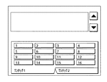
図8は、第3の実施の形態における操作部2012の表示画面を示す図である。
【0062】
表示画面には、1から16までのワンタッチボタンが表示される。各ボタンには、宛先情報テーブルを基に送信回数の多い順に宛先名称が表示される。ワンタッチボタン表示領域において、左上のボタン1がもっとも送信回数の多い宛先に割り当てられ、右下のボタン16が送信回数の多さ16番目の宛先に割り当てられる。これらのボタンの表示は、送信を実行する毎、また他の表示画面よりこの表示画面に遷移した場合に更新される。なお、「ワンタッチ2」タブをクリックすることにより、17以降のワンタッチボタンを表示することも可能である。
【0063】
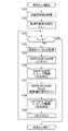
図9は、宛先情報テーブルを基にして、送信ジョブ実行時に、送信回数及び最終送信日時の更新、並びに送信回数及び最終送信日時をキーして降順ソートをそれぞれ行って送信回数降順リスト及び最終送信日時降順リストを作成する処理の手順を示すフローチャートである。
【0064】
ユーザが操作部2012から送信ジョブを発行すると、宛先管理コンポーネント3002が本処理を開始する。
【0065】
まずステップS21で、発行された送信ジョブに含まれるインデックス数(送信宛先数)Aを取得し、ステップS22で、処理件数nを1に初期化する。
【0066】
次にステップS23で、処理件数nがインデックス数Aより大きいか否かを判別し、大きいならば本処理を終了し、ジョブ管理コンポーネント3003に処理を引き渡す。
【0067】
処理件数nがインデックス数A以下であれば、ステップS24に進み、発行された送信ジョブに含まれる全インデックスのうちn番目のインデックスが対応する宛先情報レコードRnを、宛先情報テーブルから取得する。そしてステップS25で、宛先情報レコードRnのSendCount欄のデータを1だけインクリメントする。そして、宛先情報テーブルの全データをコピーし、コピーして得られた全データに、インクリメント後の宛先情報レコードRnを戻して更新する。
【0068】
さらにステップS26で、更新後の全データにおいて、SendCount欄のデータをキーとして宛先情報レコードの降順ソートを実行し、得られたソート後の全データを送信回数降順リストとする。なお再度、ステップS24〜S25を実行する際には、宛先情報テーブルからではなく、送信回数降順リストから宛先情報レコードRnや全データを取得、コピーするようにする。
【0069】
次にステップS27で、ステップS24で取得した宛先情報レコードRnのLastSendTime欄に現在日時を上書きする。そして、宛先情報テーブルの全データをコピーし、コピーして得られた全データに、上書き後の宛先情報レコードRnを戻して更新する。
【0070】
さらにステップS28で、更新後の全データにおいて、LastSendTime欄のデータをキーとして宛先情報レコードの降順ソートを実行し、得られたソート後の全データを最終送信日時降順リストとする。
【0071】
この後、ステップS29で、処理件数nを1だけインクリメントして、ステップS23に戻る。なお再度、ステップS27〜S28を実行する際には、宛先情報テーブルからではなく、最終送信日時降順リストから宛先情報レコードRnや全データを取得、コピーするようにする。
【0072】
かくして、処理件数nがインデックス数Aより大きくなるまでステップS24〜S29が繰返されて、発行された送信ジョブに含まれる全インデックスに対応する宛先情報レコードの更新が行われ、更に、送信回数及び最終送信日時をキーにした宛先情報レコードの降順ソートがそれぞれ実行されて、送信回数降順リスト及び最終送信日時降順リストが作成される。
【0073】
図10は、送信回数に応じてインデックスをワンタッチボタンに割り当てる場合に、操作部コンポーネント3001で行われる宛先名称表示処理の手順を示すフローチャートである。
【0074】
操作部コンポーネント3001は本処理を、送信ジョブを実行する毎に、また他の表示画面からワンタッチボタンの表示画面に遷移したとき実行する。
【0075】
まず、ステップS31で、宛先情報テーブルに登録された送信宛先数Bの取得を行い、ステップS32で、処理件数nを1に初期化する。
【0076】
次にステップS33で、処理件数nが送信宛先数Bより大きいか否か、または処理件数nがワンタッチボタン表示数MAXより大きいか否かを判別する。ワンタッチボタン最大表示数MAXは、操作部2012の表示画面に表示可能なワンタッチボタンの数である。処理件数nが送信宛先数Bまたはワンタッチボタン表示数MAXより大きい場合は本処理を終了する。
【0077】
処理件数nが送信宛先数B以下であり、且つ処理件数nがワンタッチボタン表示数MAX以下である場合はステップS34に進み、送信回数降順リストのn番目のインデックスを取得する。そしてステップS35で、取得したn番目のインデックスに対応する宛先情報レコードRnを取得し、ステップS36で、取得した宛先情報レコードRn内の宛先名称を、未割り当てのワンタッチボタンのうち一番若い番号のボタンに割り当てて表示する。この後、ステップS37で、処理件数nを1だけインクリメントしてステップS33に戻る。
【0078】
かくして、処理件数nが送信宛先数Bまたはワンタッチボタン表示数MAXより大きくなるまで、ステップS34〜S37が繰返され、これによって、各ワンタッチボタンに送信回数降順にインデックスが割り当てられ、対応の宛先名称が表示される。
【0079】
なお、最終送信日時に応じてインデックスをワンタッチボタンに割り当てる場合には、図10のステップS34において、送信回数降順リストに代わり、最終送信日時降順リストを参照してn番目のインデックスを取得するようにする。これにより、各ワンタッチボタンに最終送信日時降順にインデックスが割り当てられ、対応の宛先名称が表示される。
【0080】
以上のようにして、第3の実施の形態では、各ワンタッチボタンに対して、使い勝手のよいインデックスの割り当てを行うことが可能となる。
【0081】
(第4の実施の形態)
次に第4の実施の形態を説明する。
【0082】
図11は、第4の実施の形態に係る複合機器の構成を示すブロック図である。この複合機器は、送受信機能を備えたデジタル複写機である。
【0083】
この複合機器は、画像形成部101、制御部102、フィニッシャー103、スキャナ部104、操作部105、複数の受信インターフェース106、複数の送信インターフェース107から構成されている。受信インターフェース106及び送信インターフェース107は、複数の相手装置との間で送受信処理を行う。制御部102は、その主要部が中央処理装置(CPU)108と記憶装置(メモリ)109とから構成されている。記憶装置109には、宛先帳(宛先情報テーブル)と転送条件設定帳(送信指令書テーブル)とが格納され、また一時保存領域が設定される。
【0084】
図12(A)は転送条件設定帳に記載される転送条件(送信指令書)の一例を示し、図12(B)は宛先帳の一例を示す図である。
【0085】
転送条件において、「条件ID(インデックスID)」は転送条件の識別符号を表し、「受信」は対応転送データを送信してきた相手装置を表し、「日時」は対応転送データを受信した日時を表し、「電話番号」は対応転送データを送信してきた相手装置の電話番号を表し、「転送宛先」は対応転送データを送信すべき相手装置の宛先を表す。「転送宛先」には宛先帳におけるIDが記載される。
【0086】
宛先帳は、データの送信先の宛名の一覧表であり、それぞれの宛先にID(識別符号)が付されている。例えば、転送条件の転送宛先に「ID2」と記載されている場合、宛先帳を参照すると、その転送宛先は「E−Mail:aa@bb.cc」であることが分かる。
【0087】
図13は、転送条件を転送条件設定帳に入力する際にユーザが使用する、操作部105に表示される画面を示す図である。
【0088】
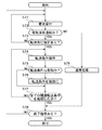
図14は、宛先帳に記載された宛先の1つが消去されるときに制御部102で行われる転送処理の手順を示したフローチャートである。
【0089】
まず、、中央処理装置108が処理要求通知を受け付け(S41)、該受け付けた処理要求通知の内容が、宛先帳から宛先を消去することを求める通知であるか否かを判定する(S42)。処理要求通知が、例えば転送宛先を検索することを要求する通知などであって、ステップS42の判定がNoならば、そうした要求に沿った通常の処理を行う(S50)。その後、本処理の終了指示があるか否かを判定し(S49)、終了指示があれば本処理を終了し、終了指示がなければ、ステップS41に戻って次の処理要求通知を受け付ける。
【0090】
ステップS42で、受け付けた処理要求通知の内容が、宛先帳から宛先を消去することを求める通知(宛先消去通知)であると判定されたならば、中央処理装置108は、記憶装置109に格納された転送条件設定帳の各転送条件を参照して、宛先消去通知に添付された消去すべき宛先名(宛先帳のIDで表示)を、転送宛先として設定されている転送条件が存在するか否かを判定する(S43)。存在しないならばステップS41に戻り、存在するならば、消去すべき宛先名(宛先帳のID)を基に、記憶装置108に格納された宛先帳から、対応の宛先名(宛先情報)を取得する(S44)。そして、取得した宛先名(宛先情報)を記憶装置108の一時保存領域に保存する(S45)。なおこの段階で、別の処理プログラムにおいて、宛先帳から消去要求のあった宛先が消去される。
【0091】
続いて、転送条件設定帳に記載された転送条件の中から、宛先消去通知に添付された消去すべき宛先名(宛先帳のID)を転送宛先として設定されている転送条件を抽出し(S46)、抽出された転送条件に設定されている転送宛先を、記憶装置108の一時保存領域に変更する(S47)。すなわちこの後、別の処理プログラムにおいて、宛先帳に代わって記憶装置108の一時保存領域が参照され、一時保存領域に保存された宛先名(宛先情報)に対して送信処理が行われることになる。
【0092】
次に、転送条件設定帳に記載された転送条件で、宛先消去通知に添付された消去すべき宛先名(宛先帳のID)を転送宛先として設定されている転送条件の全てに対して、ステップS47の処理が完了したか否かを判定し(S48)、完了していない転送条件があればステップS46へ戻り、完了していればステップS49へ進む。
【0093】
以上のようにして、転送条件には転送宛先として記載されているにも拘らず、宛先帳からは消去されてしまった宛先に対して、正常に送信処理を行なうことができる。
【0094】
なお、第4の実施の形態では、データを他の装置から受信して、更に他の装置に転送する場合を想定して説明をしているが、本発明は、自己装置で発生したデータを他の装置に送信する場合にも適用できることは言うまでもない。
【0095】
(第5の実施の形態)
次に第5の実施の形態を説明する。
【0096】
第5の実施の形態の構成は、基本的に第4の実施の形態の構成と同じであるので、第5の実施の形態の説明においては、第4の実施の形態の構成を流用する。
【0097】
第5の実施の形態では、制御部102で行われる転送処理が、第4の実施の形態と一部異なっている。
【0098】
図15は、宛先帳に記載された宛先の1つが消去されたとき、または転送条件設定帳に記載された転送条件の転送宛先に変更が生じたときに制御部102で行われる転送処理の手順を示したフローチャートである。図15では、図14に示す第4の実施の形態におけるステップと同一内容のステップに同一のステップ番号を付してその説明を省略する。
【0099】
まず、ステップS60がステップS47とステップS48との間に新たに追加される。ステップS47により、抽出された転送条件に設定されている転送宛先が、記憶装置108の一時保存領域に変更された後、ステップS60では、対象転送条件における転送宛先では、宛先情報が宛先帳ではなく記憶装置108の一時保存領域に保存されている旨を、操作部105に表示させてユーザに知らせる。
【0100】
そして、ステップS51〜S56が新たに追加される。
【0101】
ステップS42で、受け付けた処理要求通知の内容が、宛先帳から宛先を消去することを求める通知ではないと判定されたならば、中央処理装置106は、受け付けた処理要求通知の内容が、転送条件内の転送宛先を変更することを求める通知(転送宛先変更通知)であるか否かを判定する(S51)。ステップS51での判定がNoならば、要求に沿った通常の処理を行う(S56)。
【0102】
ステップS51での判定がYesならば、転送宛先変更通知に添付された変更すべき転送条件名を基に、記憶装置108に格納された転送条件設定帳から対応の転送条件を抽出する(S52)。抽出された転送条件において、転送宛先変更通知で通知された変更内容に従い転送宛先(宛先帳のIDで表現)を変更する(S53)。変更後の転送条件は転送条件設定帳において対応位置に上書きされる。
【0103】
続いて、ステップS45で記憶装置108の一時保存領域に保存された宛先名(宛先情報)を参照して、ステップS53で変更された転送条件が、その転送宛先を変更することがあり得るので、中央処理装置106は、ステップS53で変更された転送条件が、そうした参照を行う最後の転送条件であるか否かを判定する(S54)。すなわち、ステップS53で変更された転送条件が、ステップS48でYesの判定になる転送条件であるか否かを判定する。ステップS54の判定がYesならば、記憶装置108の一時保存領域に保存されていた宛先名(宛先情報)を消去し(S55)、NoならばステップS55をスキップしてステップS49に移る。
【0104】
以上のように、記憶装置108の一時保存領域に保存しておくことが不要になった宛先名(宛先情報)は消去し、これによって、記憶装置108において記憶資源の節約が図られる。
【0105】
なお、第5の実施の形態では、記憶装置108の一時保存領域に保存しておくことが不要になった宛先名(宛先情報)の消去は、その宛先名(宛先情報)を参照する転送条件がなくなったときであるが、これに代わって、一定保存期間が過ぎたとき、当該宛先を記憶装置108の一時保存領域から自動的に消去するようにしてもよい。
【0106】
(第6の実施の形態)
次に第6の実施の形態を説明する。
【0107】
第6の実施の形態の構成は、基本的に第4の実施の形態の構成と同じであるので、第6の実施の形態の説明においては、第4の実施の形態の構成を流用する。
【0108】
第6の実施の形態では、制御部102で行われる転送処理が、第4の実施の形態と一部異なっている。
【0109】
図16は、第6の実施の形態における、宛先帳に記載された宛先の1つが消去され、該宛先情報が記憶装置108の一時保存領域に一時的に保存されているときに制御部102で行われる転送処理の手順を示したフローチャートである。
【0110】
まず、中央処理装置108が、宛先名を指定されて編集要求を受け取ると(S61)、該指定された宛先名が、記憶装置108の一時保存領域に一時的に保存されている宛先名(宛先情報)であるか否かを判定する(S62)。ステップS62の判定がNoならば、通常の処理を行ない(S69)、本処理を終了する。一方、記憶装置108の一時保存領域に一時的に保存されている宛先名であるならば、宛先帳を呼び出し(S63)、宛先帳の中に新たなIDと宛先記載部分を取得し、記憶装置108の一時保存領域に一時的に保存されていた宛先名(宛先情報)を、該取得した宛先記載部分に記載する(S64)。
【0111】
つぎに、記憶装置108の一時保存領域に一時的に保存されている宛先名を自己の転送宛先にしている転送条件において、上記取得した新たなIDを転送宛先に上書きする(S65)。続いて中央処理装置108は、記憶装置108の一時保存領域に一時的に保存されている宛先名を自己の転送宛先にしている転送条件の全てにおいて、上記取得した新たなIDを転送宛先に上書きすることが終了したか否かを判定し(S66)、ステップS66の判定がYesならば、記憶装置108の一時保存領域に一時的に保存されていた宛先名(宛先情報)を消去して(S67)本処理を終了する。ステップS66の判定がNoならばステップS65に戻る。
【0112】
以上のようにして、記憶装置108の一時保存領域に一時保存された宛先名を宛先帳で新たな宛先として設定し、その宛先に対応するIDを、関連する転送条件の転送宛先に上書きすれば、第4及び第5の実施の形態の場合と異なり、宛先帳を有効に利用した恒久的な宛先名(宛先情報)とそれに対応するIDとの関係になる。
【0113】
(第7の実施の形態)
次に第7の実施の形態を説明する。
【0114】
第7の実施の形態の構成は、基本的に第4の実施の形態の構成と同じであるので、第7の実施の形態の説明においては、第4の実施の形態の構成を流用する。
【0115】
第7の実施の形態では、制御部102で行われる転送処理が、第4の実施の形態と一部異なっている。
【0116】
図17は、第7の実施の形態における、転送条件の属性に有効/無効が付加され、宛先帳に記載された宛先の1つが消去されたときに制御部102で行われる転送処理の手順を示したフローチャートである。
【0117】
まず、、中央処理装置108が処理要求通知を受け付け(S71)、該受け付けた処理要求通知の内容が、宛先帳から宛先を消去することを求める通知であるか否かを判定する(S72)。処理要求通知が、例えば転送宛先を検索することを要求する通知などであって、ステップS72の判定がNoならば、そうした要求に沿った通常の処理を行う(S79)。その後、本処理の終了指示があるか否かを判定し(S78)、終了指示があれば本処理を終了し、終了指示がなければ、ステップS71に戻って次の処理要求通知を受け付ける。
【0118】
ステップS72で、受け付けた処理要求通知の内容が、宛先帳から宛先を消去することを求める通知(宛先消去通知)であると判定されたならば、中央処理装置108は、記憶装置109に格納された転送条件設定帳の各転送条件を参照して、宛先消去通知に添付された消去すべき宛先名(宛先帳のIDで表示)を、転送宛先として設定されている転送条件が存在するか否かを判定する(S73)。存在しないならばステップS71に戻り、存在するならば、そうした消去すべき宛先名(宛先帳のID)を転送宛先として設定されている転送条件を取得する(S74)。そして、中央処理装置108は、取得した転送条件が、「有効」の属性を持っているか否かを判定する(S75)。すなわち第7の実施の形態では、各転送条件に対して、転送処理対象とすべき転送条件であることを示す「有効」、または転送処理対象とすべきでない転送条件であることを示す「無効」の属性を設定する。そして、各転送条件に基づく転送処理を行うときには、この属性を参照して属性に沿った処理を行う。
【0119】
ステップS75の判定がYesならば、取得した転送条件の属性を「無効」(自己が検索の対象となり得ない)とし(S76)、NoならばステップS76をスキップする。
【0120】
続いて中央処理装置106は、転送条件設定帳において、宛先消去通知に添付された消去すべき宛先名(宛先帳のID)を転送宛先として設定されている転送条件のすべてに対して、ステップS74〜S76の処理が実行されたか否かを判定する(S77)。ステップS77での判定がYesならば、ステップS78に移り、NoならばステップS74に戻る。
【0121】
以上のようにして、宛先帳から宛先が削除された際、この宛先を転送宛先として保持している転送条件の属性を「無効」とし、これによって、宛先帳から削除されている宛先に対して転送条件が転送処理を無駄に行うことを防止している。
【0122】
なお、前述した各実施の形態の機能を実現するソフトウェアのプログラムコードを記憶した記憶媒体を、システムあるいは装置に供給し、そのシステムあるいは装置のコンピュータ(またはCPUやMPU)が記憶媒体に格納されたプログラムコードを読み出して実行することによっても、本発明が達成されることは言うまでもない。
【0123】
この場合、記憶媒体から読み出されたプログラムコード自体が、前述の各実施の形態の機能を実現することになり、そのプログラムコードを記憶した記憶媒体が本発明を構成することになる。
【0124】
プログラムコードを供給するための記憶媒体として、例えば、フロッピィディスク、ハードディスク、光ディスク、光磁気ディスク、CD−ROM、CD−R、磁気テープ、不揮発性のメモリカード、ROMなどを用いることができる。
【0125】
また、コンピュータが読み出したプログラムコードを実行することにより、前述した各実施の形態の機能が実現されるだけでなく、そのプログラムコードの指示に基づき、コンピュータ上で稼働しているOSなどが実際の処理の一部または全部を行い、その処理によって前述した各実施の形態の機能が実現される場合も、本発明に含まれることは言うまでもない。
【0126】
さらに、記憶媒体から読み出されたプログラムコードが、コンピュータに挿入された機能拡張ボードやコンピュータに接続された機能拡張ユニットに備わるメモリに書き込まれた後、そのプログラムコードの指示に基づき、その機能拡張ボードや機能拡張ユニットに備わるCPUなどが実際の処理の一部または全部を行い、その処理によって前述した各実施の形態の機能が実現される場合も、本発明に含まれることは言うまでもない。
【0134】
【発明の効果】
本発明によれば、宛先情報テーブルから宛先情報が消去された場合でも、その宛先を送信先として設定されていた送信指令書に基づき、正常に送信処理が行われ得る。
【図面の簡単な説明】
【図1】第1の実施の形態に係る基本的なシステムの構成を示す図である。
【図2】複写機の内部構成を示すブロック図である。
【図3】コントローラユニットで実行されるデータ送信処理のソフトウェアの構成を示すブロック図である。
【図4】ジョブ管理コンポーネントが管理する送信ジョブ情報の送信ジョブ情報テーブルの一例(A)と、宛先管理コンポーネントが管理する宛先情報の宛先情報テーブルの一例(B)とを示す図である。
【図5】宛先情報の変更要求をうけたときに、第1の実施の形態におけるジョブ管理コンポーネントで行われる指定インデックス対応宛先情報テーブルの変更処理の手順を示すフローチャートである。
【図6】宛先情報の変更要求をうけたときに、第2の実施の形態におけるジョブ管理コンポーネントで行われる指定インデックス対応宛先情報テーブルの変更処理の手順を示すフローチャートである。
【図7】第3の実施の形態における宛先管理コンポーネントが管理する宛先情報テーブルの一例を示す図である。
【図8】第3の実施の形態における操作部の表示画面を示す図である。
【図9】宛先情報テーブルを基にして、送信ジョブ実行時に、送信回数及び最終送信日時の更新、並びに送信回数及び最終送信日時をキーして降順ソートをそれぞれ行って送信回数降順リスト及び最終送信日時降順リストを作成する処理の手順を示すフローチャートである。
【図10】送信回数に応じてインデックスをワンタッチボタンに割り当てる場合に、操作部コンポーネントで行われる宛先名称表示処理の手順を示すフローチャートである。
【図11】第4の実施の形態に係る複合機器の構成を示すブロック図である。
【図12】(A)は転送条件設定帳に記載される転送条件の一例を示し、(B)は宛先帳の一例を示す図である。
【図13】転送条件を転送条件設定帳に入力する際にユーザが使用する、操作部に表示される画面を示す図である。
【図14】宛先帳に記載された宛先の1つが消去されたときに制御部で行われる転送処理の手順を示したフローチャートである。
【図15】宛先帳に記載された宛先の1つが消去されたとき、または転送条件設定帳に記載された転送条件の転送宛先に変更が生じたときに制御部で行われる転送処理の手順を示したフローチャートである。
【図16】第6の実施の形態における、宛先帳に記載された宛先の1つが消去され、該宛先情報が記憶装置の一時保存領域に一時的に保存されているときに制御部で行われる転送処理の手順を示したフローチャートである。
【図17】第7の実施の形態における、転送条件の属性に有効/無効が付加され、宛先帳に記載された宛先の1つが消去されたときに制御部で行われる転送処理の手順を示したフローチャートである。
【符号の説明】
101 画像形成部
102 制御部
103 フィニッシャー
104 スキャナ部
105 操作部
106 複数の受信インターフェース
107 複数の送信インターフェース
108 中央処理装置
109 記憶装置
1001 複写機
1002 プリンタ
1003 ファクシミリ
l004 データベース/メールサーバ
1005 クライアントコンピュータ
1006 イーサネット
2000 コントローラユニット(データ送信装置)
2001 CPU
2002 RAM
2003 ROM
2004 HDD
2005 イメージバスI/F
2006 操作部I/F
2007 システムバス
2008 画像バス
2010 ネットワークI/F
2011 LAN
2012 操作部
2020 デバイスI/F
2030 画像回転部
2040 画像圧縮部
2050 モデム
2051 公衆回線
2060 RIP
2070 スキャナ
2080 スキャナ画像処理部
2090 プリンタ画像処理部
2095 プリンタ
3000 送信管理コンポーネント
3001 操作部コンポーネント
3002 宛先管理コンポーネント
3003 ジョブ管理コンポーネント
3004 スキャナ管理コンポーネント
3005 プリントコンポーネント
3006 ファクシミリ送信コンポーネント
3007 データベース格納コンポーネント
3008 メール送信コンポーネント[0001]
BACKGROUND OF THE INVENTION
The present invention relates to a data transmission device, a data transmission method, and a storage medium.By specifying an index included in a destination information table including a plurality of sets with an index added to the destination information, it is possible to transmit to the destination information associated with the index.The present invention relates to a data transmission device, a data transmission method, and a storage medium.
[0003]
[Prior art]
Traditionally,In the data transmission system, the destination management component performs index storage processing of destination information, and the job management component performs transmission job execution processing. When executing a transmission job, the job management component acquires the corresponding destination information from the destination management component based on the index included in the transmission job, creates transmission job-corresponding destination information, and executes the transmission process based on this To do.
[0009]
[Problems to be solved by the invention]]
However, when the destination information is deleted from the destination information table together with the index, the transmission job set with the destination as the transmission destination cannot acquire the destination information and cannot perform the transmission process. There was a problem.
[0012]
The present invention has been made in view of such problems,Provided are a data transmission device, a data transmission method, and a storage medium that can normally perform transmission processing by a transmission job that has been set with the destination as a transmission destination even when the destination information is deleted from the destination information table thingEyesTarget.
[0015]
[Means for Solving the Problems]
To achieve the above objective,Claim1The data transmission device described in the above refers to the destination information associated with the index by designating an index included in the destination information table including a plurality of sets with the index added to the destination information. And setting means for setting a transmission table for transmitting data to the acquired destination information, and before the transmission based on the transmission table set by the setting means ends, in the destination information table, The destination information corresponding to the index included in the transmission table is deleted.RuWhether or notFirstDetermining means; andFirstBy judging meansSaidThe destination information corresponding to the index included in the transmission table is deleted.RuIs determined,The destination information to be deleted is temporarily stored in a predetermined storage destination, and theThe destination of the destination information in the transmission tableThe predeterminedControl means for controlling to switch to the save destination;After destination information is stored in the predetermined storage destination, a second determination unit that determines whether or not an index included in the transmission table is changed, and is included in the transmission table by the second determination unit When it is determined that the index to be changed is changed, the destination information corresponding to the changed index and temporarily stored in the predetermined storage destination is temporarily stored in the predetermined storage destination. A deletion step of deleting the destination information from the predetermined storage destination;It is characterized by having.
[0018]
Claim4The data transmission method described in the above section refers to the destination information table for destination information associated with the index by specifying an index included in the destination information table including a plurality of sets with the destination information indexed. In the destination information table, the setting step of setting a transmission table for transmitting data to the acquired destination information and before the transmission based on the transmission table set in the setting step is completed. The destination information corresponding to the index included in the transmission table is deleted.RuWhether or notFirstA determination step;FirstIn the judgment processSaidThe destination information corresponding to the index included in the transmission table is deleted.RuIs determined,The destination information to be deleted is temporarily stored in a predetermined storage destination, and theThe destination of the destination information in the transmission tableThe predeterminedA control process for controlling to switch to a storage destination;A second determination step of determining whether or not an index included in the transmission table is changed after the destination information is stored in the predetermined storage destination; and included in the transmission table in the second determination step A deletion step of deleting destination information corresponding to the changed index and temporarily stored in the predetermined storage destination from the predetermined storage destination when it is determined that the index to be changed is changed; ,It is characterized by having.
[0019]
A computer-readable storage medium according to
[0031]
DETAILED DESCRIPTION OF THE INVENTION
Hereinafter, embodiments of the present invention will be described with reference to the drawings.
[0032]
(First embodiment)
FIG. 1 is a diagram showing a basic system configuration according to the first embodiment.
[0033]
The
[0034]
FIG. 2 is a block diagram showing the internal configuration of the
[0035]
The
[0036]
In the
[0037]
An image bus I / F 2005 is a bus bridge that connects a
[0038]
A raster image processor (RIP) 2060 expands the PDL code into a bitmap image. The device I / F 2020 connects the
[0039]
FIG. 3 is a block diagram showing a software configuration of data transmission processing executed by the
[0040]
In the figure, the
The
[0041]
FIG. 4 is a diagram illustrating an example (A) of a transmission job information table for transmission job information managed by the
[0042]
The destination information is input for each destination from the
[0043]
The transmission job information table is created by the user specifying a job ID with the
[0044]
FIG. 5 is a flowchart showing the procedure of the specified index correspondence destination information table change process performed by the
[0045]
When the user makes a destination information change request from the
[0046]
In step S2, the number of destinations j, which is the number of index IDs included in the transmission job being executed or on standby, is acquired from the transmission job information table. All index IDs included in the middle transmission job are acquired as a destination number list A. In step S4, the processing number n is initialized to 1.
[0047]
In step S5, it is determined whether or not the processing number n is larger than the destination number j. If the processing number n is equal to or less than the destination number j, the process proceeds to step S6 to determine whether or not the index An that is the nth index ID in the destination number list A is equal to the index C. If they are not equal, the process proceeds to step S7, the process number n is incremented by 1, and the process returns to step S5.
[0048]
If it is determined in step S6 that the index An is equal to the index C, the process proceeds to step S8, and the index ID corresponding to the index An is rewritten to a value 0 indicating change of the destination information in the designated index corresponding destination information table. When the index ID is 0, the
[0049]
As described above, the destination information corresponding to the designated index ID included in the transmission job information table is extracted from the destination information table together with the index ID, and the destination information is changed in the designated index correspondence destination information table created in advance. Since the
[0050]
(Second Embodiment)
Next, a second embodiment will be described.
[0051]
Since the configuration of the second embodiment is basically the same as the configuration of the first embodiment, the configuration of the first embodiment is used in the description of the second embodiment.
[0052]
In the second embodiment, when a destination information change request is received, the change processing of the designated index corresponding destination information table performed by the
[0053]
FIG. 6 is a flowchart illustrating a procedure of a specified index correspondence destination information table change process performed by the
[0054]
If it is determined in step S6 that the index An is equal to the index C, the process proceeds to step S11, and destination information corresponding to the designated index ID included in the transmission job information table is extracted from the destination information table together with the index ID in advance. In the created designated index corresponding destination information table, the index ID corresponding to the index An and the corresponding destination information are deleted. In step S12, the destination number j is decremented by 1, and the destination information change process is terminated.
[0055]
As described above, the destination information requested to be changed is deleted together with the index ID in the designated index corresponding destination information table. Since the
[0056]
(Third embodiment)
Next, a third embodiment will be described.
[0057]
Since the configuration of the third embodiment is basically the same as the configuration of the first embodiment, the configuration of the first embodiment is used in the description of the third embodiment.
[0058]
FIG. 7 is a diagram illustrating an example of a destination information table managed by the
[0059]
The destination information is input in advance from the
[0060]
Each of these destination information is treated as a record, and an index ID is automatically given to each destination information.
[0061]
FIG. 8 is a diagram illustrating a display screen of the
[0062]
One-
[0063]
FIG. 9 shows, based on the destination information table, when a transmission job is executed, updates the number of transmissions and the last transmission date and time, and sorts in descending order by using the number of transmissions and the last transmission date and time. It is a flowchart which shows the procedure of the process which produces a date descending order list.
[0064]
When the user issues a transmission job from the
[0065]
First, in step S21, the number of indexes (number of transmission destinations) A included in the issued transmission job is acquired. In step S22, the processing number n is initialized to 1.
[0066]
Next, in step S23, it is determined whether or not the processing number n is larger than the index number A. If it is larger, the processing is terminated and the processing is transferred to the
[0067]
If the processing number n is equal to or less than the index number A, the process proceeds to step S24, and the destination information record Rn corresponding to the nth index among all the indexes included in the issued transmission job is acquired from the destination information table. In step S25, the data in the SendCount field of the destination information record Rn is incremented by one. Then, all the data in the destination information table is copied, and the destination information record Rn after the increment is returned to all the data obtained by copying and updated.
[0068]
Furthermore, in step S26, descending order sorting of the destination information records is executed using the data in the SendCount field as a key in all the updated data, and the obtained all sorted data is set as a descending number of transmission times list. When steps S24 to S25 are executed again, the destination information record Rn and all data are acquired and copied not from the destination information table but from the transmission frequency descending list.
[0069]
In step S27, the current date and time are overwritten in the LastSendTime field of the destination information record Rn acquired in step S24. Then, all the data in the destination information table is copied, and the overwritten destination information record Rn is returned and updated to all the data obtained by copying.
[0070]
Further, in step S28, in the updated data, the destination information record is sorted in descending order using the data in the LastSendTime field as a key, and the obtained sorted data is used as the last transmission date and time descending list.
[0071]
Thereafter, in step S29, the processing number n is incremented by 1, and the process returns to step S23. When steps S27 to S28 are executed again, the destination information record Rn and all data are acquired and copied not from the destination information table but from the last transmission date descending list.
[0072]
Thus, steps S24 to S29 are repeated until the processing number n is greater than the index number A, and the destination information records corresponding to all indexes included in the issued transmission job are updated. Sorting in descending order of the destination information records using the transmission date and time as a key is performed, and a transmission frequency descending list and a last transmission date and time descending list are created.
[0073]
FIG. 10 is a flowchart illustrating a procedure of a destination name display process performed by the
[0074]
The
[0075]
First, in step S31, the number of transmission destinations B registered in the destination information table is acquired. In step S32, the processing number n is initialized to 1.
[0076]
In step S33, it is determined whether or not the processing number n is larger than the transmission destination number B, or whether or not the processing number n is larger than the one-touch button display number MAX. The one-touch button maximum display number MAX is the number of one-touch buttons that can be displayed on the display screen of the
[0077]
When the processing number n is equal to or less than the transmission destination number B and the processing number n is equal to or less than the one-touch button display number MAX, the process proceeds to step S34, and the nth index in the transmission frequency descending list is acquired. In step S35, the destination information record Rn corresponding to the acquired nth index is acquired. In step S36, the destination name in the acquired destination information record Rn is set to the lowest number among the unassigned one-touch buttons. Assign to the button to display. Thereafter, in step S37, the processing number n is incremented by 1, and the process returns to step S33.
[0078]
Thus, steps S34 to S37 are repeated until the processing number n becomes larger than the transmission destination number B or the one-touch button display number MAX, whereby an index is assigned to each one-touch button in descending order of the number of transmissions, and the corresponding destination name is set. Is displayed.
[0079]
When assigning an index to the one-touch button according to the last transmission date and time, in step S34 of FIG. 10, the nth index is acquired by referring to the last transmission date and time descending list instead of the transmission frequency descending list. To do. Thereby, an index is assigned to each one-touch button in descending order of the last transmission date and the corresponding destination name is displayed.
[0080]
As described above, in the third embodiment, it is possible to assign a convenient index to each one-touch button.
[0081]
(Fourth embodiment)
Next, a fourth embodiment will be described.
[0082]
FIG. 11 is a block diagram illustrating a configuration of a composite device according to the fourth embodiment. This composite device is a digital copying machine having a transmission / reception function.
[0083]
This composite device includes an
[0084]
FIG. 12A shows an example of transfer conditions (transmission command) written in the transfer condition setting book, and FIG. 12B shows an example of an address book.
[0085]
In the transfer condition, “condition ID (index ID)” represents an identification code of the transfer condition, “reception” represents the partner apparatus that transmitted the corresponding transfer data, and “date and time” represents the date and time when the corresponding transfer data was received. , “Telephone number” represents the telephone number of the partner apparatus that has transmitted the corresponding transfer data, and “transfer destination” represents the destination of the partner apparatus to which the corresponding transfer data is to be transmitted. The “forwarding destination” describes an ID in the destination book.
[0086]
The address book is a list of addressees of data transmission destinations, and an ID (identification code) is assigned to each address. For example, when “ID2” is described in the transfer destination of the transfer condition, it can be seen that the transfer destination is “E-Mail: aa@bb.cc” by referring to the destination book.
[0087]
FIG. 13 is a diagram illustrating a screen displayed on the
[0088]
FIG. 14 is a flowchart illustrating a transfer process performed by the
[0089]
First, the
[0090]
If it is determined in step S42 that the content of the received processing request notification is a notification requesting deletion of the destination from the destination book (destination deletion notification), the
[0091]
Subsequently, from the transfer conditions described in the transfer condition setting book, a transfer condition in which the destination name (address book ID) attached to the address deletion notification is set as the transfer destination is extracted (S46). ), The transfer destination set in the extracted transfer condition is changed to the temporary storage area of the storage device 108 (S47). That is, thereafter, in another processing program, the temporary storage area of the
[0092]
Next, with respect to all the transfer conditions in which the destination name (address book ID) to be deleted attached to the destination deletion notification is set as the transfer destination in the transfer conditions described in the transfer condition setting book It is determined whether the process of S47 is completed (S48). If there is a transfer condition that is not completed, the process returns to step S46, and if it is completed, the process proceeds to step S49.
[0093]
As described above, transmission processing can be normally performed on a destination that has been deleted from the destination book despite being described as a transfer destination in the transfer condition.
[0094]
In the fourth embodiment, the description is given on the assumption that data is received from another device and further transferred to another device. However, in the present invention, data generated by the self device is used. Needless to say, the present invention can also be applied to transmission to other devices.
[0095]
(Fifth embodiment)
Next, a fifth embodiment will be described.
[0096]
Since the configuration of the fifth embodiment is basically the same as the configuration of the fourth embodiment, the configuration of the fourth embodiment is used in the description of the fifth embodiment.
[0097]
In the fifth embodiment, transfer processing performed by the
[0098]
FIG. 15 shows a procedure of transfer processing performed by the
[0099]
First, step S60 is newly added between step S47 and step S48. After the transfer destination set in the extracted transfer condition is changed to the temporary storage area of the
[0100]
Then, steps S51 to S56 are newly added.
[0101]
If it is determined in step S42 that the content of the received processing request notification is not a notification requesting deletion of the destination from the destination book, the
[0102]
If the determination in step S51 is Yes, the corresponding transfer condition is extracted from the transfer condition setting book stored in the
[0103]
Subsequently, referring to the destination name (destination information) stored in the temporary storage area of the
[0104]
As described above, destination names (destination information) that are no longer required to be stored in the temporary storage area of the
[0105]
In the fifth embodiment, deletion of a destination name (destination information) that is no longer required to be stored in the temporary storage area of the
[0106]
(Sixth embodiment)
Next, a sixth embodiment will be described.
[0107]
Since the configuration of the sixth embodiment is basically the same as the configuration of the fourth embodiment, the configuration of the fourth embodiment is used in the description of the sixth embodiment.
[0108]
In the sixth embodiment, transfer processing performed by the
[0109]
FIG. 16 shows the
[0110]
First, when the
[0111]
Next, under the transfer condition in which the destination name temporarily stored in the temporary storage area of the
[0112]
As described above, the destination name temporarily stored in the temporary storage area of the
[0113]
(Seventh embodiment)
Next, a seventh embodiment will be described.
[0114]
Since the configuration of the seventh embodiment is basically the same as the configuration of the fourth embodiment, the configuration of the fourth embodiment is used in the description of the seventh embodiment.
[0115]
In the seventh embodiment, transfer processing performed by the
[0116]
FIG. 17 shows the procedure of the transfer process performed by the
[0117]
First, the
[0118]
If it is determined in step S 72 that the content of the received processing request notification is a notification requesting deletion of the destination from the destination book (destination deletion notification), the
[0119]
If the determination in step S75 is Yes, the acquired transfer condition attribute is set to “invalid” (self cannot be a search target) (S76), and if no, step S76 is skipped.
[0120]
Subsequently, in the transfer condition setting book, the
[0121]
As described above, when a destination is deleted from the address book, the attribute of the transfer condition that holds this address as a transfer address is set to “invalid”. The transfer condition prevents wasteful transfer processing.
[0122]
A storage medium storing software program codes for realizing the functions of the above-described embodiments is supplied to the system or apparatus, and the computer (or CPU or MPU) of the system or apparatus is stored in the storage medium. It goes without saying that the present invention can also be achieved by reading and executing the program code.
[0123]
In this case, the program code itself read from the storage medium realizes the functions of the above-described embodiments, and the storage medium storing the program code constitutes the present invention.
[0124]
As a storage medium for supplying the program code, for example, a floppy disk, hard disk, optical disk, magneto-optical disk, CD-ROM, CD-R, magnetic tape, nonvolatile memory card, ROM, or the like can be used.
[0125]
Further, by executing the program code read by the computer, not only the functions of the above-described embodiments are realized, but the OS running on the computer based on the instruction of the program code is actually used. Needless to say, the present invention also includes a case in which the functions of the above-described embodiments are realized by performing part or all of the processing and the processing.
[0126]
Further, after the program code read from the storage medium is written to a memory provided in a function expansion board inserted into the computer or a function expansion unit connected to the computer, the function expansion is performed based on the instruction of the program code. Needless to say, the present invention includes a case where the CPU or the like provided in the board or the function expansion unit performs part or all of the actual processing and the functions of the above-described embodiments are realized by the processing.
[0134]
【The invention's effect】
According to the present invention, even when the destination information is deleted from the destination information table, the transmission process can be normally performed based on the transmission instruction document in which the destination is set as the transmission destination.
[Brief description of the drawings]
FIG. 1 is a diagram illustrating a basic system configuration according to a first embodiment;
FIG. 2 is a block diagram showing an internal configuration of the copying machine.
FIG. 3 is a block diagram showing a software configuration of data transmission processing executed by the controller unit.
FIG. 4 is a diagram illustrating an example (A) of a transmission job information table for transmission job information managed by a job management component and an example (B) of a destination information table for destination information managed by a destination management component.
FIG. 5 is a flowchart illustrating a procedure of a specified index correspondence destination information table change process performed by the job management component according to the first embodiment when a destination information change request is received;
FIG. 6 is a flowchart illustrating a procedure of a specified index correspondence destination information table change process performed by a job management component according to the second embodiment when a destination information change request is received;
FIG. 7 is a diagram illustrating an example of a destination information table managed by a destination management component according to the third embodiment.
FIG. 8 is a diagram showing a display screen of an operation unit in the third embodiment.
FIG. 9 shows, based on the destination information table, when a transmission job is executed, updates the number of transmissions and the last transmission date and time, and sorts in descending order by using the number of transmissions and the last transmission date and time, respectively, and a transmission number descending list and final transmission. It is a flowchart which shows the procedure of the process which produces a date descending order list.
FIG. 10 is a flowchart illustrating a procedure of a destination name display process performed by an operation unit component when an index is assigned to a one-touch button according to the number of transmissions.
FIG. 11 is a block diagram illustrating a configuration of a composite device according to a fourth embodiment.
12A shows an example of transfer conditions described in a transfer condition setting book, and FIG. 12B shows an example of an address book.
FIG. 13 is a diagram showing a screen displayed on the operation unit used by a user when inputting transfer conditions into a transfer condition setting book.
FIG. 14 is a flowchart illustrating a transfer process performed by the control unit when one of the destinations described in the destination book is deleted.
FIG. 15 shows a procedure of transfer processing performed by the control unit when one of the destinations described in the destination book is deleted or when the transfer destination of the transfer conditions described in the transfer condition setting book is changed. It is the shown flowchart.
FIG. 16 is performed by the control unit when one of the destinations described in the destination book is deleted and the destination information is temporarily stored in the temporary storage area of the storage device in the sixth embodiment It is the flowchart which showed the procedure of the transfer process.
FIG. 17 shows a procedure of transfer processing performed by the control unit when valid / invalid is added to the attribute of the transfer condition and one of the destinations described in the destination book is deleted in the seventh embodiment It is a flowchart.
[Explanation of symbols]
101 Image forming unit
102 controlPart
103 Finisher
104 Scanner unit
105 OperationPart
106 Multiple receiving interfaces
107 Multiple sending interfaces
108 Central processing equipmentPlace
109 memoryPlace
1001 Copying machine
1002 Printer
1003 Facsimile
l004 Database / Mail Server
1005 Client computer
1006 Ethernet
2000 Controller unit (data transmission device)
2001 CPU
2002 RAM
2003 ROM
2004 HDD
2005 Image Bus I / F
2006 Operation unit I / F
2007 System bus
2008 Image bus
2010 Network I / F
2011 LAN
2012 operationPart
2020 Device I / F
2030 Image rotation unit
2040 Image compression unit
2050 modem
2051 Public line
2060 RIP
2070 scanner
2080 Scanner image processing unit
2090 Printer image processing unit
2095 Printer
3000 Transmission Management Component
3001 Operation component
3002 Destination management component
3003 Job management component
3004 Scanner management component
3005 Print component
3006 Facsimile transmission component
3007 Database storage component
3008 Email sending component
Claims (5)
前記設定手段で設定された送信テーブルに基づく送信が終了する前に、前記宛先情報テーブルにおいて、当該送信テーブルに含まれるインデックスに対応する宛先情報が削除されるか否か判定する第1の判定手段と、
前記第1の判定手段により前記送信テーブルに含まれるインデックスと対応する宛先情報が削除されると判定された場合、当該削除される宛先情報を所定の保存先に一時保存させるとともに、前記送信テーブルにおける宛先情報の参照先を前記所定の保存先に切り替えるよう制御する制御手段と、
前記所定の保存先に宛先情報が保存された後、前記送信テーブルに含まれるインデックスが変更されるか否かを判定する第2の判定手段と、
前記第2の判定手段により前記送信テーブルに含まれるインデックスが変更されると判定された場合、当該変更されるインデックスに対応する宛先情報であって前記所定の保存先に一時保存されている宛先情報を当該所定の保存先から削除する削除手段と、
を有することを特徴とするデータ送信装置。By specifying an index included in a destination information table including a plurality of sets with an index added to the destination information, the destination information associated with the index is acquired by referring to the destination information table, and the acquired Setting means for setting a transmission table for transmitting data to the destination information;
Before transmission based on the transmission table set by the setting means is completed, wherein the destination information table, if the destination information corresponding to the index Ru deleted whether determines first determination means included in the transmission table When,
If the destination information corresponding to the index included in the transmission table is determined to Ru is removed by the first determining means, causes temporarily store the destination information is the deleted predetermined destination, in the transmission table Control means for controlling to switch the reference destination of the destination information to the predetermined storage destination;
Second determination means for determining whether or not an index included in the transmission table is changed after the destination information is stored in the predetermined storage destination;
When it is determined by the second determination means that the index included in the transmission table is changed, the destination information corresponding to the changed index and temporarily stored in the predetermined storage destination Delete means for deleting from the predetermined storage location,
A data transmission device comprising:
前記設定工程で設定された送信テーブルに基づく送信が終了する前に、前記宛先情報テーブルにおいて、当該送信テーブルに含まれるインデックスに対応する宛先情報が削除されるか否か判定する第1の判定工程と、
前記第1の判定工程において前記送信テーブルに含まれるインデックスと対応する宛先情報が削除されると判定された場合、当該削除される宛先情報を所定の保存先に一時保存させるとともに、前記送信テーブルにおける宛先情報の参照先を前記所定の保存先に切り替えるよう制御する制御工程と、
前記所定の保存先に宛先情報が保存された後、前記送信テーブルに含まれるインデックスが変更されるか否かを判定する第2の判定工程と、
前記第2の判定工程において前記送信テーブルに含まれるインデックスが変更されると判定された場合、当該変更されるインデックスに対応する宛先情報であって前記所定の保存先に一時保存されている宛先情報を当該所定の保存先から削除する削除工程と、
を有することを特徴とするデータ送信方法。By specifying an index included in a destination information table including a plurality of sets with an index added to the destination information, the destination information associated with the index is acquired by referring to the destination information table, and the acquired A setting step for setting a transmission table for transmitting data to the destination information;
Before transmission based on the transmission table set by the setting step is completed, the in the destination information table, the first determination step of determining whether the destination information is Ru is removed corresponding to the index included in the transmission table When,
If the index with corresponding destination information included in the transmission table at said first determination step is determined to Ru is removed, along with to temporarily store the destination information is the deleted predetermined destination, in the transmission table A control step of controlling to switch the reference destination of the destination information to the predetermined storage destination;
A second determination step of determining whether or not an index included in the transmission table is changed after the destination information is stored in the predetermined storage destination;
When it is determined that the index included in the transmission table is changed in the second determination step, the destination information corresponding to the changed index and temporarily stored in the predetermined storage destination Deleting from the predetermined storage location,
A data transmission method characterized by comprising:
Priority Applications (1)
| Application Number | Priority Date | Filing Date | Title |
|---|---|---|---|
| JP2000253981A JP4439699B2 (en) | 2000-08-24 | 2000-08-24 | Data transmission apparatus, data transmission method, and storage medium |
Applications Claiming Priority (1)
| Application Number | Priority Date | Filing Date | Title |
|---|---|---|---|
| JP2000253981A JP4439699B2 (en) | 2000-08-24 | 2000-08-24 | Data transmission apparatus, data transmission method, and storage medium |
Publications (3)
| Publication Number | Publication Date |
|---|---|
| JP2002077472A JP2002077472A (en) | 2002-03-15 |
| JP2002077472A5 JP2002077472A5 (en) | 2007-10-04 |
| JP4439699B2 true JP4439699B2 (en) | 2010-03-24 |
Family
ID=18743003
Family Applications (1)
| Application Number | Title | Priority Date | Filing Date |
|---|---|---|---|
| JP2000253981A Expired - Fee Related JP4439699B2 (en) | 2000-08-24 | 2000-08-24 | Data transmission apparatus, data transmission method, and storage medium |
Country Status (1)
| Country | Link |
|---|---|
| JP (1) | JP4439699B2 (en) |
Cited By (1)
| Publication number | Priority date | Publication date | Assignee | Title |
|---|---|---|---|---|
| CN102420924A (en) * | 2010-09-27 | 2012-04-18 | 佳能株式会社 | Image processing apparatus, control method thereof, and storage medium |
Families Citing this family (3)
| Publication number | Priority date | Publication date | Assignee | Title |
|---|---|---|---|---|
| JP6099957B2 (en) * | 2012-12-10 | 2017-03-22 | キヤノン株式会社 | Image forming apparatus, data editing method, and program |
| JP6197683B2 (en) * | 2014-02-16 | 2017-09-20 | ブラザー工業株式会社 | Facsimile device, control server, and computer program |
| JP6953226B2 (en) * | 2017-08-04 | 2021-10-27 | ソニーセミコンダクタソリューションズ株式会社 | Communication devices, communication methods, programs, and communication systems |
-
2000
- 2000-08-24 JP JP2000253981A patent/JP4439699B2/en not_active Expired - Fee Related
Cited By (3)
| Publication number | Priority date | Publication date | Assignee | Title |
|---|---|---|---|---|
| CN102420924A (en) * | 2010-09-27 | 2012-04-18 | 佳能株式会社 | Image processing apparatus, control method thereof, and storage medium |
| CN102420924B (en) * | 2010-09-27 | 2014-08-13 | 佳能株式会社 | Image processing apparatus and control method |
| US9516191B2 (en) | 2010-09-27 | 2016-12-06 | Canon Kabushiki Kaisha | Image processing apparatus, control method thereof, and storage medium |
Also Published As
| Publication number | Publication date |
|---|---|
| JP2002077472A (en) | 2002-03-15 |
Similar Documents
| Publication | Publication Date | Title |
|---|---|---|
| US7031003B2 (en) | Image processing apparatus, control method of image processing apparatus, and storage medium | |
| US7321445B2 (en) | Image processing apparatus and control method therefor | |
| US7443532B2 (en) | Network scanner system | |
| US8472050B2 (en) | File transmission apparatus, method and file version management system | |
| US7236273B2 (en) | Data communication apparatus | |
| US8464264B2 (en) | Information processing apparatus and method of controlling same | |
| US8302095B2 (en) | Workflow processing method and apparatus for determining the existence of data in the storage location and changing the setting information and name of storage location | |
| JP2008191711A (en) | Image forming apparatus, method of controlling image forming apparatus, program, and storage medium | |
| JP4439699B2 (en) | Data transmission apparatus, data transmission method, and storage medium | |
| US8363256B2 (en) | Image processing apparatus, image processing system and image processing method | |
| US20020131074A1 (en) | Data transmission device, method and program | |
| JP2001251454A (en) | Image processing apparatus, control method for image processing apparatus, and storage medium | |
| JP4093993B2 (en) | Image reading apparatus, image forming apparatus including the same, and scanner system | |
| JP2000358144A (en) | Picture input/output system and its control method | |
| JP2023072812A (en) | Information processing apparatus, method for controlling information processing apparatus, program therefor, and image processing system | |
| JP3697841B2 (en) | Form processing apparatus and method | |
| JP2009140069A (en) | Printing system | |
| JP2005222376A (en) | Data transmission system, method and program | |
| JP2003060833A (en) | Image input/output system | |
| JP4100859B2 (en) | Data communication apparatus and storage method of destination information | |
| JP3433012B2 (en) | Facsimile system | |
| JP4208386B2 (en) | Communication apparatus and data transmission method | |
| JPH06284235A (en) | Image forming storage | |
| JP2000004339A (en) | Image input/output device | |
| KR100338074B1 (en) | Method for subscription transmission of document data in the facsimile |
Legal Events
| Date | Code | Title | Description |
|---|---|---|---|
| RD03 | Notification of appointment of power of attorney |
Free format text: JAPANESE INTERMEDIATE CODE: A7423 Effective date: 20060324 |
|
| RD05 | Notification of revocation of power of attorney |
Free format text: JAPANESE INTERMEDIATE CODE: A7425 Effective date: 20070626 |
|
| A521 | Written amendment |
Free format text: JAPANESE INTERMEDIATE CODE: A523 Effective date: 20070821 |
|
| A621 | Written request for application examination |
Free format text: JAPANESE INTERMEDIATE CODE: A621 Effective date: 20070821 |
|
| A977 | Report on retrieval |
Free format text: JAPANESE INTERMEDIATE CODE: A971007 Effective date: 20090928 |
|
| A131 | Notification of reasons for refusal |
Free format text: JAPANESE INTERMEDIATE CODE: A131 Effective date: 20091006 |
|
| A521 | Written amendment |
Free format text: JAPANESE INTERMEDIATE CODE: A523 Effective date: 20091207 |
|
| TRDD | Decision of grant or rejection written | ||
| A01 | Written decision to grant a patent or to grant a registration (utility model) |
Free format text: JAPANESE INTERMEDIATE CODE: A01 Effective date: 20100105 |
|
| A01 | Written decision to grant a patent or to grant a registration (utility model) |
Free format text: JAPANESE INTERMEDIATE CODE: A01 |
|
| A61 | First payment of annual fees (during grant procedure) |
Free format text: JAPANESE INTERMEDIATE CODE: A61 Effective date: 20100106 |
|
| FPAY | Renewal fee payment (event date is renewal date of database) |
Free format text: PAYMENT UNTIL: 20130115 Year of fee payment: 3 |
|
| R150 | Certificate of patent or registration of utility model |
Free format text: JAPANESE INTERMEDIATE CODE: R150 |
|
| FPAY | Renewal fee payment (event date is renewal date of database) |
Free format text: PAYMENT UNTIL: 20140115 Year of fee payment: 4 |
|
| LAPS | Cancellation because of no payment of annual fees |