JP4438552B2 - Safety PLC, sequence program creation support software, and sequence program determination method - Google Patents
Safety PLC, sequence program creation support software, and sequence program determination method Download PDFInfo
- Publication number
- JP4438552B2 JP4438552B2 JP2004221734A JP2004221734A JP4438552B2 JP 4438552 B2 JP4438552 B2 JP 4438552B2 JP 2004221734 A JP2004221734 A JP 2004221734A JP 2004221734 A JP2004221734 A JP 2004221734A JP 4438552 B2 JP4438552 B2 JP 4438552B2
- Authority
- JP
- Japan
- Prior art keywords
- sequence program
- safety
- type information
- input device
- output
- Prior art date
- Legal status (The legal status is an assumption and is not a legal conclusion. Google has not performed a legal analysis and makes no representation as to the accuracy of the status listed.)
- Expired - Lifetime
Links
Images


Classifications
-
- G—PHYSICS
- G05—CONTROLLING; REGULATING
- G05B—CONTROL OR REGULATING SYSTEMS IN GENERAL; FUNCTIONAL ELEMENTS OF SUCH SYSTEMS; MONITORING OR TESTING ARRANGEMENTS FOR SUCH SYSTEMS OR ELEMENTS
- G05B19/00—Program-control systems
- G05B19/02—Program-control systems electric
- G05B19/04—Program control other than numerical control, i.e. in sequence controllers or logic controllers
- G05B19/05—Programmable logic controllers, e.g. simulating logic interconnections of signals according to ladder diagrams or function charts
- G05B19/058—Safety, monitoring
-
- G—PHYSICS
- G05—CONTROLLING; REGULATING
- G05B—CONTROL OR REGULATING SYSTEMS IN GENERAL; FUNCTIONAL ELEMENTS OF SUCH SYSTEMS; MONITORING OR TESTING ARRANGEMENTS FOR SUCH SYSTEMS OR ELEMENTS
- G05B9/00—Safety arrangements
- G05B9/02—Safety arrangements electric
-
- G—PHYSICS
- G05—CONTROLLING; REGULATING
- G05B—CONTROL OR REGULATING SYSTEMS IN GENERAL; FUNCTIONAL ELEMENTS OF SUCH SYSTEMS; MONITORING OR TESTING ARRANGEMENTS FOR SUCH SYSTEMS OR ELEMENTS
- G05B2219/00—Program-control systems
- G05B2219/10—Plc systems
- G05B2219/11—Plc I-O input output
- G05B2219/1179—Safety, on error, fault, block, inhibit output
-
- G—PHYSICS
- G05—CONTROLLING; REGULATING
- G05B—CONTROL OR REGULATING SYSTEMS IN GENERAL; FUNCTIONAL ELEMENTS OF SUCH SYSTEMS; MONITORING OR TESTING ARRANGEMENTS FOR SUCH SYSTEMS OR ELEMENTS
- G05B2219/00—Program-control systems
- G05B2219/10—Plc systems
- G05B2219/13—Plc programming
- G05B2219/13196—Check if instruction for special module is valid for that module
-
- G—PHYSICS
- G05—CONTROLLING; REGULATING
- G05B—CONTROL OR REGULATING SYSTEMS IN GENERAL; FUNCTIONAL ELEMENTS OF SUCH SYSTEMS; MONITORING OR TESTING ARRANGEMENTS FOR SUCH SYSTEMS OR ELEMENTS
- G05B2219/00—Program-control systems
- G05B2219/10—Plc systems
- G05B2219/13—Plc programming
- G05B2219/13198—Safety, forbid dangerous instruction, instruction order while programming
-
- G—PHYSICS
- G05—CONTROLLING; REGULATING
- G05B—CONTROL OR REGULATING SYSTEMS IN GENERAL; FUNCTIONAL ELEMENTS OF SUCH SYSTEMS; MONITORING OR TESTING ARRANGEMENTS FOR SUCH SYSTEMS OR ELEMENTS
- G05B2219/00—Program-control systems
- G05B2219/10—Plc systems
- G05B2219/14—Plc safety
- G05B2219/14007—Plc as standalone for safety control of machine
Landscapes
- Physics & Mathematics (AREA)
- General Physics & Mathematics (AREA)
- Engineering & Computer Science (AREA)
- Automation & Control Theory (AREA)
- Programmable Controllers (AREA)
Description
本発明は、複数の入力機器を組み合わせて出力機器を制御するシーケンスプログラムを書替え可能な安全PLC、安全PLCに書き込むシーケンスプログラムの作成支援ソフトウェア、及びシーケンスプログラムの判定方法に関する。 The present invention relates to a safety PLC capable of rewriting a sequence program for controlling an output device by combining a plurality of input devices, software for supporting creation of a sequence program to be written in the safety PLC, and a sequence program determination method.
従来、工場の生産ライン等では、一般PLC(Programmable Logic Controller)を用いて、種々の入力機器(スイッチ、センサ等)からの導通状態に関する信号(ONまたはOFFの情報)を入力し、種々の入力機器を所望する形態に組み合わせた(直列または並列に組み合わせた)シーケンスプログラムを用いて、出力機器(リレー、モータ等)を制御(ONまたはOFF信号を出力等)している。
なお、種々の入力機器の中から任意に選択した入力機器を直列または並列に任意に組み合わせたシーケンスプログラムを作成する場合、通常、ユーザはシーケンスプログラム作成支援ソフトウェアを用いてラダー回路を作成し、作成したラダー回路に基づいたデータを作成して一般PLCに書き込むことで、一般PLCに所望する動作をさせている。
近年では、一般PLCに対して安全に特化したいわゆる安全PLCの要求が高まっている。安全PLCでは、理想的には安全が保証された入力機器を用いて、出力機器への出力を、安全が保証された出力とする。しかし、実際には全ての入力機器が安全が保証された入力機器ではない場合もある。安全が保証されている入力機器と安全が保証されていない入力機器とを混在させたシーケンスプログラムを作成した場合、出力機器への出力の安全が保証されているか否かは、ユーザが判定しなければならない。
なお、先行技術として特許文献1には、ユニット単体の構成を簡略化しつつフェイルセーフを実現でき、ユニット単体ひいてはシステム全体としてもコストダウンを図ることのできる安全コントローラが提案されている。
Note that when creating a sequence program that arbitrarily combines input devices arbitrarily selected from various input devices in series or in parallel, the user usually creates a ladder circuit using the sequence program creation support software. By creating data based on the ladder circuit and writing it to the general PLC, the general PLC is allowed to perform a desired operation.
In recent years, there has been an increasing demand for so-called safety PLC specialized in safety with respect to general PLC. In the safety PLC, ideally, an input device with which safety is guaranteed is used, and an output to the output device is an output with safety guaranteed. However, not all input devices are actually input devices for which safety is guaranteed. When creating a sequence program that mixes input devices that are guaranteed to be safe and input devices that are not guaranteed to be safe, the user must determine whether the output safety to the output device is guaranteed. I must.
As a prior art,
ユーザがシーケンスプログラム作成支援ソフトウェアを用いてシーケンスプログラム(ラダー回路等)を作成する場合、どのような入力機器を用いることも可能であり、またどのような組み合わせ(直列または並列に組み合わせ)にすることも可能である。
従って、安全が保証された入力機器や安全が保証されていない入力機器を混在させて、なおかつ直列または並列に複雑に組み合わせてシーケンスプログラムを作成することができてしまう。このように作成されたシーケンスプログラムの出力部が(特に数十個〜数百個の入力機器を組み合わせたようなシーケンスプログラムの出力部が)、安全が保証された出力であるか否かを判定するためには、従来ではユーザの手作業で行っており、膨大な労力が必要であった。またユーザの手作業による判定では、誤判定の可能性もあった。
安全が保証されている入力機器と安全が保証されていない入力機器とを混在させた場合、安全が保証される組み合わせ(直列等)と安全が保証されない組み合わせ(並列等)が存在するためである。
When a user creates a sequence program (ladder circuit, etc.) using sequence program creation support software, any input device can be used, and any combination (series or parallel combination) can be used. Is also possible.
Accordingly, it is possible to create a sequence program by mixing input devices with which safety is guaranteed or input devices with which safety is not guaranteed and combining them in series or in parallel. Determine whether the output part of the sequence program created in this way (especially the output part of a sequence program that combines several tens to several hundreds of input devices) is a safe output. In order to do so, it has been done manually by the user, and enormous effort has been required. In addition, there is a possibility of erroneous determination in the determination by the user's manual work.
This is because there are combinations that guarantee safety (series, etc.) and combinations that do not guarantee safety (parallel, etc.) when input devices that are guaranteed safety and input devices that are not guaranteed safety are mixed. .
特許文献1に記載の従来技術では、作成されたシーケンスプログラムを複数のCPUで演算して結果を比較することで、演算結果の信頼性を向上させているが、シーケンスプログラムそのものの安全性を向上させることはできない。
また、他の従来技術としては、各入力機器が安全であるか否かを予め設定しておき、シーケンスプログラム作成支援ソフトウェアにてシーケンスプログラム(ラダー回路等)を表示させた際、安全が保証されていない入力機器を識別可能に表示するものもある。しかし、単体の入力機器が安全であるか否かを表示しているにすぎず、シーケンスプログラムの出力が、安全が保証されている出力であるか否かは、結局ユーザの手作業により、膨大な労力を費やして判定せざるを得ない。
In the conventional technique described in
As another conventional technique, whether or not each input device is safe is set in advance, and safety is guaranteed when the sequence program (ladder circuit, etc.) is displayed by the sequence program creation support software. Some input devices are displayed in an identifiable manner. However, it is only displaying whether or not a single input device is safe, and whether or not the output of the sequence program is an output for which safety is assured depends on the user's manual work. Judgment must be made with great effort.
本発明は、このような点に鑑みて創案されたものであり、シーケンスプログラムの出力部が、安全が保証された出力であるか否かを自動的に判定し、より短時間にかつより正確に安全が保証された出力であるか否かをユーザが判断できる、安全PLC、シーケンスプログラム作成支援ソフトウェア及びシーケンスプログラムの判定方法を提供することを課題とする。 The present invention was devised in view of such points, and the sequence program output unit automatically determines whether or not the output is guaranteed to be safe, and in a shorter time and more accurately. It is an object of the present invention to provide a safety PLC, sequence program creation support software, and a sequence program determination method that allow a user to determine whether or not the output is guaranteed to be safe.
上記課題を解決するための手段として、本発明の第1発明は、請求項1に記載されたとおりの安全PLCである。
請求項1に記載の安全PLCは、複数の入力機器の導通状態に関する信号が入力される入力手段と、入力された入力機器の中から選択した任意の入力機器を直列または並列に組み合わせて構成したシーケンスプログラムを記憶する記憶手段と、シーケンスプログラムと各入力機器の導通状態に関する信号とに基づいて演算結果を求める演算手段と、演算手段の演算結果を出力部から出力して出力機器を制御する出力手段とを備え、シーケンスプログラムを書替え可能な安全PLCである。
記憶手段には、各入力機器に対応させて、安全が保証されていることを示す第1種類情報または安全が保証されていないことを示す第2種類情報が設定された入力機器種類情報が、予め記憶されている。
そして安全PLCは、シーケンスプログラムと入力機器種類情報とに基づいて、出力部に対応するシーケンスプログラムが、安全が保証されている構成であるか否かを判定し、安全が保証されていない構成であると判定した場合、報知手段に出力するとともに、出力部に接続された出力機器を安全側に制御する。
As means for solving the above-mentioned problems, the first invention of the present invention is a safety PLC as described in
The safety PLC according to
In the storage means, input device type information in which first type information indicating that safety is guaranteed or second type information indicating that safety is not guaranteed is set corresponding to each input device , Stored in advance .
Based on the sequence program and the input device type information, the safety PLC determines whether or not the sequence program corresponding to the output unit has a guaranteed safety configuration. When it determines with there being, it outputs to an alerting | reporting means, and controls the output apparatus connected to the output part to the safe side.
また、本発明の第2発明は、請求項2に記載されたとおりのシーケンスプログラム作成支援ソフトウェアである。
請求項2に記載のシーケンスプログラム作成支援ソフトウェアは、複数の入力機器の導通状態に関する信号が入力される入力手段と、入力された入力機器の中から選択した任意の入力機器を直列または並列に組み合わせて構成したシーケンスプログラムを記憶する記憶手段と、シーケンスプログラムと各入力機器の導通状態に関する信号とに基づいて演算結果を求める演算手段と、演算手段の演算結果を出力部から出力して出力機器を制御する出力手段とを備え、シーケンスプログラムを書替え可能な安全PLCの記憶手段に記憶させるシーケンスプログラムを作成する際に使用する、シーケンスプログラム作成支援ソフトウェアであって、コンピュータを、各入力機器に対応させて、安全が保証されていることを示す第1種類情報または安全が保証されていないことを示す第2種類情報が設定された入力機器種類情報を記憶する入力機器記憶手段、入力機器記憶手段に記憶されている入力機器種類情報と、対象となるシーケンスプログラムと、に基づいて、当該シーケンスプログラムに対応する出力部が、安全が保証されている構成であるか否かを判定する安全判定手段、安全判定手段が判定した結果を識別可能に表示する判定結果表示手段、として機能させるためのシーケンスプログラム作成支援ソフトウェアである。
A second invention of the present invention is sequence program creation support software as set forth in
The sequence program creation support software according to
また、本発明の第3発明は、請求項3に記載されたとおりのシーケンスプログラム作成支援ソフトウェアである。
請求項3に記載のシーケンスプログラム作成支援ソフトウェアは、請求項2に記載のシーケンスプログラム作成支援ソフトウェアであって、コンピュータを、安全判定手段にて判定した結果、安全が保証されている構成でないと判定した場合、当該シーケンスプログラムを安全PLCに書き込むことを禁止するように設定することが可能な書き込み禁止設定手段、として機能させるためのシーケンスプログラム作成支援ソフトウェアである。
A third invention of the present invention is sequence program creation support software as set forth in
The sequence program creation support software according to
また、本発明の第4発明は、請求項4に記載されたとおりのシーケンスプログラム作成支援ソフトウェアである。
請求項4に記載のシーケンスプログラム作成支援ソフトウェアは、請求項2または3に記載のシーケンスプログラム作成支援ソフトウェアであって、シーケンスプログラム作成支援ソフトウェアでは、複数のシーケンスプログラムを作成可能であるとともに、あるシーケンスプログラムの出力部を別のシーケンスプログラムの入力機器として利用することが可能であり、コンピュータを、安全判定手段にて判定した結果、安全が保証されている構成でないと判定された出力部が選択された場合、当該出力部の安全が保証されている構成でないと判定された原因を含む自身または別のシーケンスプログラムの中から最初に安全が保証されている構成でないと判定された出力部を含むシーケンスプログラムを表示する原因シーケンスプログラム表示手段、原因シーケンスプログラム表示手段にて表示したシーケンスプログラムにおいて原因となった入力機器または出力部の少なくとも一方を識別可能に表示する原因個所表示手段、として機能させるためのシーケンスプログラム作成支援ソフトウェアである。
The fourth invention of the present invention is sequence program creation support software as set forth in claim 4.
The sequence program creation support software according to claim 4 is the sequence program creation support software according to
また、本発明の第5発明は、請求項5に記載されたとおりのシーケンスプログラムの判定方法である。
請求項5に記載のシーケンスプログラムの判定方法は、請求項1に記載の安全PLCまたは請求項2〜4のいずれかに記載のシーケンスプログラム作成支援ソフトウェアにおいて、対象となるシーケンスプログラムの出力部の安全が保証されている構成であるか否かを判定するシーケンスプログラムの判定方法において、判定結果を、常に安全が保証されていることを示す第1種類情報と、常に安全が保証されていないことを示す第2種類情報と、安全が保証されている場合と保証されていない場合の双方があり得る結果として安全が保証されていないことを示す第3種類情報の3種類に分類し、シーケンスプログラムが第1種類情報の入力機器のみで構成されている場合、出力部の判定結果は第1種類情報であると判定するステップ、シーケンスプログラムが第2種類情報の入力機器のみで構成されている場合、出力部の判定結果は第2種類情報であると判定するステップ、シーケンスプログラムに第1種類情報の入力機器と第2種類情報の入力機器とが混在する場合、シーケンスプログラムの出力部に至る経路中のいずれの部分においても、第2種類情報の入力機器の導通状態が第1種類情報の入力機器の導通状態よりも優先される部分が検出されない場合に、当該シーケンスプログラムの出力部の判定結果は第1種類情報であると判定するステップ、及びシーケンスプログラムの出力部に至る経路中の少なくとも一部において、第2種類情報の入力機器の導通状態が第1種類情報の入力機器の導通状態よりも優先される部分が検出された場合に、当該シーケンスプログラムの出力部の判定結果は第3種類情報であると判定するステップとからなるシーケンスプログラムの判定方法である。
The fifth aspect of the present invention is a sequence program determination method as defined in claim 5.
The sequence program determination method according to claim 5 is the safety PLC according to
請求項1に記載の安全PLCを用いれば、シーケンスプログラムの出力が、安全が保証されている構成であるか否かを、安全PLCが自動的に判定するので、ユーザの手作業を必要とせず、より短時間かつより正確に、安全が保証された出力であるか否かをユーザが判断できる。また、安全が保証されていないと判定された場合は報知されるので、ユーザは安全が保証されていないことを的確に認識することができる。また、安全が保証されていないと判定された場合は出力機器を安全側に制御するので便利である。
If the safety PLC according to
また、請求項2に記載のシーケンスプログラム作成支援ソフトウェアによれば、シーケンスプログラム作成支援ソフトウェアが、対象となるシーケンスプログラムの出力が、安全が保証されている構成であるか否かを自動的に判定する。
そしてユーザは、識別可能に表示された判定結果(安全が保証されているか否かの判定結果)を見ることで、安全が保証された出力であるか否かを判断することができる。
このため、ユーザの手作業を必要とせず、より短時間かつより正確に、安全が保証された出力であるか否かをユーザが判断できる。
According to the sequence program creation support software according to
Then, the user can determine whether or not the output is a safe output by viewing the determination result displayed so as to be identifiable (a determination result indicating whether or not safety is guaranteed).
For this reason, the user can determine whether or not the output is assured of safety in a shorter time and more accurately without requiring manual operation of the user.
また、請求項3に記載のシーケンスプログラム作成支援ソフトウェアによれば、安全が保証されている構成でないと判定されたシーケンスプログラムを、ユーザが誤って安全PLCに書き込むことを禁止できるため、便利である。 According to the sequence program creation support software of the third aspect, it is convenient because the user can be prohibited from accidentally writing the sequence program that is determined not to have a safe configuration to the safety PLC. .
また、請求項4に記載のシーケンスプログラム作成支援ソフトウェアによれば、安全が保証されている構成でないと判定されたシーケンスプログラムの出力部に対して、当該出力部がそのように判定された原因となった入力機器(または他のシーケンスプログラムの入力機器または出力部)を識別可能に表示する。このため、ユーザが、シーケンスプログラムを修正して安全が保証されている構成に直す作業において、どの部分を修正すべきか、ユーザは瞬時に判断できる。
このため、ユーザによるシーケンスプログラムの修正において、ユーザは、短時間にかつ正確に修正すべき部分を認識することができ、非常に便利である。
According to the sequence program creation support software according to claim 4, for the output part of the sequence program that is determined not to have a safety-guaranteed configuration, the reason why the output part is so determined The displayed input device (or the input device or output unit of another sequence program) is displayed in an identifiable manner. For this reason, the user can instantly determine which part should be corrected in the operation in which the user corrects the sequence program so as to ensure the safety.
For this reason, when the user corrects the sequence program, the user can recognize a portion to be corrected accurately in a short time, which is very convenient.
また、請求項5に記載のシーケンスプログラムの判定方法によれば、安全が保証されている入力機器と安全が保証されていない入力機器とを混在させた場合、安全が保証される組み合わせ(直列等)と安全が保証されない組み合わせ(並列等)を適切に判定することができる。 In addition, according to the sequence program determination method of the fifth aspect, when an input device that is guaranteed to be safe and an input device that is not guaranteed to be safe are mixed, a combination that guarantees safety (such as serial connection). ) And combinations that are not guaranteed to be safe (parallel, etc.) can be appropriately determined.
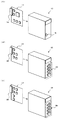
以下に本発明を実施するための最良の形態を図面を用いて説明する。図1は、本発明の安全PLC1(Programmable Logic Controller)を構成する制御ユニット10と入力ユニット20と出力ユニット30の概略外観図を示している。
●[安全PLCの外観(図1)]
まず図1(A)〜(C)に、制御ユニット10(演算手段に相当)、入力ユニット20(入力手段に相当)、出力ユニット30(出力手段に相当)の外観の例を示す。
安全PLC1は、制御ユニット10と入力ユニット20と出力ユニット30とで構成され、入出力の数に応じて入力ユニット20及び出力ユニット30が増設される。
入力ユニット20内には制御ユニット10と接続するためのコネクタ22を備えた入力ボード21が収容されており、複数の入力機器(スイッチ、センサ等)からの配線が接続される入力端子25が設けられている。
出力ユニット30内には制御ユニット10と接続するためのコネクタ32を備えた出力ボード31が収容されており、複数の出力機器(リレー、モータ等)への配線が接続される出力端子35が設けられている。
制御ユニット10内には入力ユニット20及び出力ユニット30と接続するためのコネクタ12を備えた制御ボード21が収容されており、パソコン等の端末装置を接続可能なコネクタ15が設けられている。
The best mode for carrying out the present invention will be described below with reference to the drawings. FIG. 1 shows a schematic external view of a
● [Appearance of safety PLC (Fig. 1)]
First, FIGS. 1A to 1C show examples of the appearance of the control unit 10 (corresponding to the calculation means), the input unit 20 (corresponding to the input means), and the output unit 30 (corresponding to the output means).
The
An
An
A
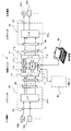
●[安全PLCのブロック構成及び接続例(図2)]
次に図2を用いて安全PLC1のブロック構成及び接続の例について説明する。
入力ユニット20の入力端子25には、複数の入力機器(スイッチ40a、センサ40b等)からの配線が接続され、複数の入力機器の導通状態に関する信号(ONまたはOFFの情報等)が入力される。入力された導通状態に関する信号は、インターフェース21a(以下、インターフェースをI/Fと記載する)及びコネクタ22を介して制御ユニット10に伝送される。
● [Block configuration of safety PLC and connection example (Fig. 2)]
Next, an example of the block configuration and connection of the
To the
制御ユニット10は、CPU11aを中心に構成され、RAM11b、ROM11c(記憶手段に相当)が設けられている。ROM11cには、EEPROM、FlashROM等の書替え可能なROMが用いられ、任意の入力機器を直列または並列に組み合わせて構成したシーケンスプログラムと、各入力機器に対応させて第1種類情報(当該入力機器は安全が保証されていることを示す情報)または第2種類情報(当該入力機器は安全が保証されていないことを示す情報)が記憶された入力機器種類情報51a(図3(A)参照)が記憶されている。ユーザは端末機器50を用いて、入力機器種類情報51aを作成可能であり、作成した入力機器種類情報51aを制御ユニット10に記憶させる(書き込む)ことが可能である。
なお、ROM11cには、I/F11fを介して端末装置50、一般PLC60(安全に特化していない他のPLC)等と通信を行うプログラム等も格納されている。
CPU11aは、ROM11cに記憶されているシーケンスプログラムと、コネクタ12及びI/F11dを介して入力ユニット20から入力される各入力機器からの導通状態に関する信号とに基づいた演算結果を、I/F11e及びコネクタ12を介して出力ユニット30に出力する。
The
The ROM 11c also stores a program for communicating with the
The
なお、一般PLC60との通信データには、一般PLCに入力された入力機器の導通状態に関する信号も含まれる(この入力機器は第2種類情報に相当する)。
第1種類情報の入力機器の例としては、接点が2重系で構成された非常停止ボタン等がある。また、第2種類情報の入力機器の例としては、単一の接点で構成された一般的なスイッチや、一般PLCから通信で入力される入力機器の情報等がある。
ユーザは端末装置50を用いてシーケンスプログラム作成支援ソフトウェアを起動して、任意の入力機器を直列または並列に組み合わせて構成したシーケンスプログラムを作成可能である。また、作成したシーケンスプログラムを制御ユニット10に記憶させる(書き込む)ことも可能である。
Note that the communication data with the
As an example of the input device of the first type information, there is an emergency stop button or the like whose contacts are configured in a double system. Also, examples of the input device of the second type information include a general switch configured with a single contact, information on an input device input by communication from a general PLC, and the like.
A user can create a sequence program that is configured by combining arbitrary input devices in series or in parallel by activating sequence program creation support software using the
出力ユニット30の出力端子35には、複数の出力機器(モータ42a、リレー42b等)への配線が接続される。そして、シーケンスプログラムと各入力機器の導通状態に基づいて制御ユニット10にて求めた演算結果を、コネクタ32及びI/F31aを介して出力端子35に接続された出力機器に出力する。
The
●[入力機器種類情報とシーケンスプログラムの例(図3)]
次に図3(A)〜(C)を用いて、入力機器種類情報51a及び出力機器情報51bの例と、シーケンスプログラム(この場合、ラダー回路)の例について説明する。
図3(A)に示すように、入力機器種類情報51aには、入力端子番号に対応させて、入力機器名称及び入力機器種類が記憶されている。
「入力端子番号」は、入力ユニット20の接続端子25の各端子に割付けられた番号である。
「入力機器名称」は、対象の入力機器をシーケンスプログラムの中で表示する際、当該入力機器に付与する名称(識別情報)である。
「入力機器種類」には、対象となる「端子番号」に接続した入力機器が第1種類情報(この場合「S」で表示)または第2種類情報(この場合「(−)」で表示)のどちらに相当するかが記憶されている。
また、図3(B)に示すように、出力機器情報51bには、端子番号に対応させて、出力機器名称が記憶されている。
「出力端子番号」は、出力ユニット30の接続端子35の各端子に割付けられた番号である。
「出力機器名称」は、対象の出力機器をシーケンスプログラムの中で表示する際、当該出力機器に付与する名称(識別情報)である。
● [Input device type information and sequence program example (Fig. 3)]
Next, an example of input device type information 51a and output device information 51b and an example of a sequence program (in this case, a ladder circuit) will be described with reference to FIGS.
As shown in FIG. 3A, the input device name information and the input device type are stored in the input device type information 51a in association with the input terminal number.
The “input terminal number” is a number assigned to each terminal of the
The “input device name” is a name (identification information) given to the input device when the target input device is displayed in the sequence program.
In the “input device type”, the input device connected to the target “terminal number” is the first type information (in this case, indicated by “S”) or the second type information (in this case, indicated by “(−)”). It is memorized which corresponds to.
Also, as shown in FIG. 3B, the output device name is stored in the output device information 51b in association with the terminal number.
The “output terminal number” is a number assigned to each terminal of the
The “output device name” is a name (identification information) given to the output device when the target output device is displayed in the sequence program.
次に図3(C)に、ユーザが作成したシーケンスプログラム(シーケンス番号「001」)の例を示す。
図3(C)に示す例では、出力機器名称「M001」(以下、「出力M001」と記載する)は、入力機器名称「I001」(以下、「入力I001」と記載する)と入力I002の双方が導通状態となった場合、または入力I003が導通状態となった場合に、ON状態に制御される。また、入力I001及び入力I002には「S」記号が付与されており第1種類情報の入力機器であることが示されている。また、入力I003には記号が何も付与されていないため第2種類情報であることが示されている。なおユーザは、シーケンスプログラムを作成する場合、端末装置50にてシーケンスプログラム作成支援ソフトウェアを用いて各入力機器の選定及び配置(場所、直列または並列の位置)を行って作成する。図3(C)に示すシーケンスプログラム(この場合、ラダー回路)入力機器に付与される第1種類情報(この場合「S」)または第2種類情報(この場合“記号なし”)は、シーケンスプログラム作成支援ソフトウェアが、入力機器種類情報51aに基づいて自動的に付与する。
なお、通常では、複数の入力機器を用いて複数の出力機器を制御するため、ユーザは複数のシーケンスプログラムを作成する。また、図3(C)中の「シーケンス番号」は、各シーケンスプログラムに付与する名称(識別情報)である。
Next, FIG. 3C shows an example of a sequence program (sequence number “001”) created by the user.
In the example shown in FIG. 3C, the output device name “M001” (hereinafter referred to as “output M001”) is the input device name “I001” (hereinafter referred to as “input I001”) and the input I002. When both are turned on or when the input I003 is turned on, it is controlled to be ON. Further, the input I001 and the input I002 are given “S” symbols to indicate that they are input devices of the first type information. Further, since no symbol is given to the input I003, it is indicated that the information is the second type information. Note that when creating a sequence program, the user uses the sequence program creation support software in the
Normally, since a plurality of output devices are controlled using a plurality of input devices, the user creates a plurality of sequence programs. In addition, “sequence number” in FIG. 3C is a name (identification information) given to each sequence program.
●[シーケンスプログラムにおいて出力部が安全か否かを自動判定させる例(図4、図5、図6)]
(1)基本ルール
次に図4を用いて自動判定における基本ルールの例を説明し、図5を用いて実際に自動判定する手順の例を説明する。
実際の安全PLC1に搭載されるシーケンスプログラム(この場合、ラダー回路)は、使用する生産ライン設備の規模にもよるが、数十個〜数百個の入力機器が直列または並列に組み合わされたシーケンスプログラムが複数搭載されている。
そして「入力機器が2個の直列回路(第1種類情報〜第3種類情報)を、合成して1個の入力機器(新たに第1種類情報〜第3種類情報を付与)に置き換え」または「入力機器が2個の並列回路(第1種類情報〜第3種類情報)を、合成して1個の入力機器(新たに第1種類情報〜第3種類情報を付与)に置き換え」を行う作業を順次進め、シーケンスプログラムの出力部が第1種類情報〜第3種類情報のいずれに該当するか、を判定する。
● [Example of automatically judging whether the output unit is safe in the sequence program (FIGS. 4, 5, and 6)]
(1) Basic Rule Next, an example of a basic rule in automatic determination will be described with reference to FIG. 4, and an example of an actual automatic determination procedure will be described with reference to FIG.
The sequence program (in this case, ladder circuit) installed in the
And "the input device is replaced with two series circuits (first type information to third type information) and replaced with one input device (newly added first type information to third type information)" or "Input device replaces two parallel circuits (first type information to third type information) and replaces with one input device (newly added first type information to third type information)" The operation is sequentially advanced to determine which of the first type information to the third type information corresponds to the output part of the sequence program.
なお、第1種類情報とは、既に説明したように、(常に)安全が保証されていることを示す情報であり、ユーザが識別可能とするために「S」記号で表している。
また、第2種類情報とは、第1種類情報と同様に既に説明したように、(常に)安全が保証されていないことを示す情報であり、ユーザが識別可能とするために「(−)、または“記号なし”」で表している。なお、「(−)」の記号による表示は図3(A)に示す入力機器種類情報51a、図5(D)及び図7(C)に示す判定履歴情報51cにて表されており、“記号なし”は図3〜図7に示すシーケンスプログラムの入力機器または出力部(図7(A)における入力I003、出力M003等)にて表されている。
また、第3種類情報とは、第2種類情報の入力機器の導通状態が、第1種類情報の入力機器の導通状態よりも優先される場合があることを示しており、構成としては図4(A)における「並列の場合(Sと(−))」の回路構成が該当する。この第3種類情報は、ユーザが識別可能とするために「U」記号で表している。
参考までに、安全に対して優先順位をつけると、第1種類情報「S」(常に安全が保証されている)>第3種類情報「U」(安全が保証されているとは限らない)>第2種類情報「(−)“記号なし”」(常に安全が保証されていない)という優先順位となる。
As described above, the first type information is information indicating that (always) safety is guaranteed, and is represented by an “S” symbol so that the user can identify it.
Further, the second type information is information indicating that (always) safety is not guaranteed, as already described in the same manner as the first type information. Or “no symbol”. The display with the symbol “(−)” is represented by the input device type information 51a shown in FIG. 3A and the
Further, the third type information indicates that the conduction state of the input device of the second type information may have priority over the conduction state of the input device of the first type information. The circuit configuration of “in the case of parallel (S and (−))” in FIG. This third type information is represented by a “U” symbol so that the user can identify it.
For reference, if priority is given to safety, the first type information “S” (always the safety is guaranteed)> the third type information “U” (the safety is not always guaranteed) > The priority is the second type information "(-)" No symbol "" (safety is not always guaranteed).
以下、第1種類情報「S」の入力機器、第2種類情報「(−)“記号なし”」の入力機器、第3種類情報「U」の入力機器の中から2つの異なる種類の入力機器を使って直列または並列に構成した場合の合成結果のルールについて説明する。なお、単数種類の入力機器を直列または並列に組み合わせた場合は、その種類を維持した(1個の)入力機器に合成され、説明を省略している。(「S」のみの組み合わせは「S」であり、「(−)」のみの組み合わせは「(−)」であり、「U」のみの組み合わせは「U」である。) Hereinafter, two different types of input devices from among the input device of the first type information “S”, the input device of the second type information “(−)“ no symbol ””, and the input device of the third type information “U” The rule of the synthesis result when configured in series or in parallel using will be described. When a single type of input device is combined in series or in parallel, the input device is combined with (one) input device that maintains the type, and the description is omitted. (A combination of only “S” is “S”, a combination of only “(−)” is “(−)”, and a combination of only “U” is “U”.)
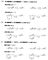
まず図4(A)に、第1種類情報「S」と第2種類情報「(−)“記号なし”」との組み合わせによる合成ルールについて説明する。
第1種類情報「S」の入力機器と第2種類情報「(−)“記号なし”」の入力機器とを直列に組み合わせた合成結果は、(1個の)第1種類情報「S」の入力機器に置き換えることができる。安全が保証されている第1種類情報「S」の入力機器にて、確実に後段の出力部を停止させるように、経路を遮断できるからである。
これに対して第1種類情報「S」の入力機器と第2種類情報「(−)“記号なし”」の入力機器とを並列に組み合わせた合成結果は、(1個の)第3種類情報「U」の入力機器に置き換えることができる。安全が保証されている第1種類情報「S」の入力機器にて、後段の出力部を停止させようとしても、安全が保証されていない第2種類情報「(−)“記号なし”」の入力機器が導通している場合は経路を遮断できないからである。なお、安全が保証されていない第2種類情報「(−)“記号なし”」の入力機器が導通していない場合は、安全が保証されている第1種類情報「S」の入力機器で経路を遮断することができる。
この『第1種類情報「S」の入力機器と第2種類情報「(−)“記号なし”」の入力機器とを並列に組み合わせた回路』が、「第2種類情報の入力機器の導通状態が第1種類情報の入力機器の導通状態よりも優先される部分」に相当する。
First, a synthesis rule based on a combination of the first type information “S” and the second type information “(−)“ no symbol ”” will be described with reference to FIG.
The result of combining the input device of the first type information “S” and the input device of the second type information “(−)“ no symbol ”” in series is the (one) first type information “S”. Can be replaced with input devices. This is because the path can be blocked so that the output unit in the subsequent stage can be surely stopped by the input device of the first type information “S” whose safety is guaranteed.
On the other hand, the composite result of combining the input device of the first type information “S” and the input device of the second type information “(−)“ no symbol ”” in parallel is (one piece) of the third type information. It can be replaced with an input device of “U”. Even if an output device of the first stage information “S” whose safety is guaranteed is to be stopped, the second type information “(−)“ No symbol ”” whose safety is not guaranteed This is because the path cannot be interrupted when the input device is conductive. In addition, when the input device of the second type information “(−)“ no symbol ”” whose safety is not guaranteed is not conductive, the route is set by the input device of the first type information “S” whose safety is guaranteed. Can be cut off.
This “circuit combining the input device of the first type information“ S ”and the input device of the second type information“ (−) “no symbol” ”in parallel” is “the conduction state of the input device of the second type information” Corresponds to “a portion that is prioritized over the conduction state of the input device of the first type information”.
次に図4(B)に、第1種類情報「S」と第3種類情報「U」との組み合わせによる合成ルールについて説明する。
第1種類情報「S」の入力機器と第3種類情報「U」の入力機器とを直列に組み合わせた合成結果は、(1個の)第3種類情報「U」の入力機器に置き換えることができる。第3種類情報「U」の入力機器内においては図4(A)の並列の場合に示すように、安全が保証されている第1種類情報「S」の入力機器にて、後段の出力部を停止させようとしても、安全が保証されていない第2種類情報「(−)“記号なし”」の入力機器が導通している場合は経路を遮断できないからである。
また第1種類情報「S」の入力機器と第3種類情報「U」の入力機器とを並列に組み合わせた合成結果も同様に、(1個の)第3種類情報「U」の入力機器に置き換えることができる。理由は上記と同様であるので説明を省略する。
Next, FIG. 4B illustrates a synthesis rule based on a combination of the first type information “S” and the third type information “U”.
The combined result obtained by combining the input device of the first type information “S” and the input device of the third type information “U” in series can be replaced with the (one) input device of the third type information “U”. it can. In the input device of the third type information “U”, as shown in the parallel case of FIG. 4A, the output unit of the subsequent stage is used in the input device of the first type information “S” for which safety is guaranteed. This is because the path cannot be interrupted when the input device of the second type information “(−)“ no symbol ”” whose safety is not guaranteed is conducted even if it is stopped.
Similarly, the combined result of combining the input device of the first type information “S” and the input device of the third type information “U” in parallel is also the input device of the (one) third type information “U”. Can be replaced. Since the reason is the same as described above, the description is omitted.
次に図4(C)に、第2種類情報「(−)“記号なし”」と第3種類情報「U」との組み合わせによる合成ルールについて説明する。
第2種類情報「(−)“記号なし”」の入力機器と第3種類情報「U」の入力機器とを直列に組み合わせた合成結果は、(1個の)第3種類情報「U」の入力機器に置き換えることができる。第3種類情報「U」の入力機器内においては図4(A)の並列の場合に示すように、安全が保証されている第1種類情報「S」の入力機器にて、後段の出力部を停止させようとしても、安全が保証されていない第2種類情報「(−)“記号なし”」の入力機器が導通している場合は経路を遮断できないからである。
また第2種類情報「(−)“記号なし”」の入力機器と第3種類情報「U」の入力機器とを並列に組み合わせた合成結果も同様に、(1個の)第3種類情報「U」の入力機器に置き換えることができる。理由は上記と同様であるので説明を省略する。
Next, FIG. 4C illustrates a synthesis rule based on a combination of the second type information “(−)“ no symbol ”” and the third type information “U”.
The result of combining the input device of the second type information “(−)“ no symbol ”” and the input device of the third type information “U” in series is the result of the (one) third type information “U”. Can be replaced with input devices. In the input device of the third type information “U”, as shown in the parallel case of FIG. 4A, the output unit of the subsequent stage is used in the input device of the first type information “S” for which safety is guaranteed. This is because the path cannot be interrupted when the input device of the second type information “(−)“ no symbol ”” whose safety is not guaranteed is conducted even if it is stopped.
Similarly, the result of combining the input device of the second type information “(−)“ no symbol ”” and the input device of the third type information “U” in parallel is also the third type information “one”. U ”input device. Since the reason is the same as described above, the description is omitted.
以上に説明した基本ルールが、シーケンスプログラム作成支援ソフトウェアに予め組み込まれており、ユーザが自動判定の実行の指示を行うと、シーケンスプログラム作成支援ソフトウェアが、対象のシーケンスプログラムと基本ルールを用いて、当該シーケンスプログラムの出力部が安全であるか否かを判定して判定結果を識別可能に表示する。(この場合、出力部に「S」、「U」、「(−)“記号なし”」のいずれかを付与して表示する。) The basic rules described above are pre-installed in the sequence program creation support software, and when the user instructs execution of automatic determination, the sequence program creation support software uses the target sequence program and the basic rules, It is determined whether or not the output part of the sequence program is safe, and the determination result is displayed in an identifiable manner. (In this case, “S”, “U”, or “(−)“ no symbol ”” is assigned to the output unit for display.)
(2)作成したシーケンスプログラムを自動判定する手順の例
まず、ユーザがシーケンスプログラム作成支援ソフトウェアを用いて、図5(A)に示すようなシーケンスプログラムを作成する。シーケンスプログラム作成支援ソフトウェアでは、シーケンスプログラムの作成エリアを複数のノード(この場合、n01〜n03)に分割しており、ユーザは各ノード間に入力機器(この場合、入力I001〜入力I003)を配置していく。例えば、隣り合うノード間には入力機器を2個以上直列に配置することはできない(2個以上の入力機器を並列に配置することは可能)。また、離れたノード間に入力機器を配置することは可能である(入力I003がこのケースに相当)。
(2) Example of Procedure for Automatically Determining Created Sequence Program First, a user creates a sequence program as shown in FIG. 5A using sequence program creation support software. In the sequence program creation support software, the sequence program creation area is divided into a plurality of nodes (in this case, n01 to n03), and the user places input devices (in this case, input I001 to input I003) between the nodes. I will do it. For example, two or more input devices cannot be arranged in series between adjacent nodes (two or more input devices can be arranged in parallel). In addition, it is possible to place input devices between remote nodes (input I003 corresponds to this case).
シーケンスプログラム作成支援ソフトウェアは、ユーザが自動判定の実行指示を行うと、対象のシーケンスプログラム(この場合、シーケンス番号「001」のシーケンスプログラムであり、以下『シーケンスプログラム「001」と記載する』)の出力部(この場合、出力M001)が安全が保証されている構成であるか否か、すなわち出力M001が「S」、「U」、「(−)“記号なし”」のいずれに該当するか、の判定を開始する。
まず図5(B)に示すように、最初のノードn01とノードn02の間に直列回路があるか否かを判定し、この場合は直列回路が存在しないので次に進む。次に最初のノードn01とノードn02の間に並列回路があるか否かを判定し、この場合は並列回路が存在しないので次に進む。
次に図5(C)に示すように、ノードn01とノードn03(ノードn02の次のノード)の間に直列回路があるか否かを判定する。この場合、入力I001「S」と入力I002「S」の直列回路があるため、この合成結果を判定(判定方法は図4参照)し、1個の入力I001A「S」に置き換える(図5(C)の上段のシーケンスプログラムを参照)。これ以上の直列回路は存在しないため、次はノードn01とノードn03の間に並列回路があるか否かを判定する。この場合、入力I001A「S」と入力I003「(−)“記号なし”」の並列回路があるため、この合成結果を判定(判定方法は図4参照)し、1個の入力I003A「U」に置き換える(図5(C)の下段のシーケンスプログラムを参照)。これで合成を終了(これ以上の合成はできない)し、合成結果、出力M001は「U」(第3種類情報)に該当すると判定する。
When the user gives an execution instruction for automatic determination, the sequence program creation support software reads the target sequence program (in this case, the sequence program with the sequence number “001”, hereinafter referred to as “sequence program“ 001 ””). Whether or not the output unit (in this case, the output M001) is configured to be safe, that is, whether the output M001 corresponds to “S”, “U”, or “(−)“ no symbol ”” The determination of is started.
First, as shown in FIG. 5B, it is determined whether or not there is a series circuit between the first node n01 and the node n02. In this case, since there is no series circuit, the process proceeds to the next. Next, it is determined whether or not there is a parallel circuit between the first node n01 and the node n02. In this case, since there is no parallel circuit, the process proceeds to the next.
Next, as shown in FIG. 5C, it is determined whether or not there is a series circuit between the node n01 and the node n03 (the node next to the node n02). In this case, since there is a series circuit of the input I001 “S” and the input I002 “S”, this combined result is determined (refer to FIG. 4 for the determination method) and replaced with one input I001A “S” (FIG. 5 ( C) (See the upper sequence program). Since there are no more series circuits, it is next determined whether or not there is a parallel circuit between the nodes n01 and n03. In this case, since there is a parallel circuit of the input I001A “S” and the input I003 “(−)“ no symbol ””, the synthesis result is determined (refer to FIG. 4 for a determination method), and one input I003A “U” is determined. (Refer to the lower sequence program in FIG. 5C). This completes the synthesis (no further synthesis is possible), and determines that the output M001 corresponds to “U” (third type information) as a result of the synthesis.
なお、シーケンスプログラム作成支援ソフトウェアは、上記の合成の判定処理を行いながら、図5(D)に示す判定履歴情報51cに、各入力機器に対して合成の判定を行った結果を記憶しておく。
判定履歴情報51cには、シーケンス番号、出力部、入力n、入力n判定の項目が設けられている。
「シーケンス番号」は、自動判定を行ったシーケンスプログラムに固有の番号である。
「出力部」は、当該シーケンスプログラムの出力の名称(この場合、M001)が記憶されている。
「出力部判定」には、当該出力部(この場合、M001)の判定結果(「S」、「U」、「(−)“記号なし”」のいずれか)が記憶される。
「入力n」には、各入力機器の名称(この場合、I001、I002、I003)が合成を行った順に記憶されていく。
「入力n判定」には、該当する入力機器を用いて合成した際の判定結果(「S」、「U」、「(−)“記号なし”」のいずれか)が記憶されている。この場合、入力I003を用いた合成を行った際、判定結果が「U」であったことが記憶されていることがわかる。なお、入力I001及び入力I002を用いた合成では判定結果が「S」であったことが記憶されている。
The sequence program creation support software stores the result of the combination determination for each input device in the
The
The “sequence number” is a number unique to the sequence program that has been automatically determined.
The “output unit” stores an output name of the sequence program (in this case, M001).
In “output unit determination”, a determination result (any of “S”, “U”, and “(−)“ no symbol ””) of the output unit (in this case, M001) is stored.
In “input n”, names of input devices (in this case, I001, I002, and I003) are stored in the order in which they are combined.
The “input n determination” stores a determination result (one of “S”, “U”, and “(−)“ no symbol ””) when combining using the corresponding input device. In this case, it is understood that when the composition using the input I003 is performed, it is stored that the determination result is “U”. In addition, it is stored that the determination result is “S” in the synthesis using the input I001 and the input I002.
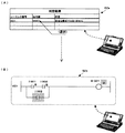
(3)判定結果の表示例
なお、シーケンスプログラム作成支援ソフトウェアは、対象となるシーケンスプログラムの判定結果が「U」または「(−)“記号なし”」(安全が保証されていない第3種類情報または第2種類情報)と判定された場合、図6(A)の例に示す判定結果画面52aにてユーザに報知する。(判定結果が「S」の場合(安全が保証されている場合)、安全が保証されている旨を報知してもよい。)
シーケンスプログラム作成支援ソフトウェアは、ユーザが判定結果画面52aの出力部を選択すると、選択された出力部に対応するシーケンスプログラムを表示し、当該シーケンスプログラムの判定結果(この場合、「U」)の原因となった入力機器を、判定履歴情報51c(図5(D)を参照)に基づいて特定する。図5(D)に示す判定履歴情報51cより、シーケンス番号「001」の出力M001が「U」である原因は、入力3判定が「U」と記憶されている入力3の入力I003が原因であると特定する。
そしてシーケンスプログラム作成支援ソフトウェアは、図6(B)に示すように、出力M001に対応するシーケンス番号「001」のシーケンスプログラムを表示するとともに、出力M001に付与した「U」、及び出力M001を「U」と判定した原因となった入力I003を、ユーザが識別可能となるように表示する(例えば当該対象部周辺の背景の色彩等を周囲と変えて目立たせる)。
(3) Display example of determination result Note that the sequence program creation support software indicates that the determination result of the target sequence program is “U” or “(−)“ no symbol ”” (third type information whose safety is not guaranteed). Alternatively, when it is determined as the second type information), the user is notified on the determination result screen 52a illustrated in the example of FIG. (When the determination result is “S” (when safety is guaranteed), it may be notified that the safety is guaranteed.)
When the user selects the output unit of the determination result screen 52a, the sequence program creation support software displays the sequence program corresponding to the selected output unit, and causes the determination result of the sequence program (in this case, “U”) The input device that has become is specified based on the
Then, as shown in FIG. 6B, the sequence program creation support software displays the sequence program with the sequence number “001” corresponding to the output M001, and “U” given to the output M001 and the output M001 as “ The input I003 that caused the determination of “U” is displayed so that the user can identify it (for example, the background color around the target portion is changed from the surrounding to make it stand out).
(4)安全PLCへの書き込みの禁止
シーケンスプログラム作成支援ソフトウェアは、ユーザが作成したシーケンスプログラム(この場合、ラダー回路)からデータを作成し、作成したデータを安全PLCに書き込むことができる。しかし、シーケンスプログラムの出力を判定した結果、少なくとも1つ以上の第2種類情報「(−)“記号なし”」または第3種類情報「U」が存在する場合、安全PLCへの書き込みを禁止する。これにより、出力が安全であることを保証されないシーケンスプログラムを、ユーザが誤って安全PLCに書き込むことを防止する。
なお、単純な表示ランプ等、機械の停止には影響のないような出力が、第2種類情報「(−)“記号なし”」または第3種類情報「U」と判定された場合は、当該シーケンスプログラムで安全PLCを動作させても「機械の安全を保証できる」場合がある。このような場合、シーケンスプログラムの出力の判定結果が第2種類情報「(−)“記号なし”」または第3種類情報「U」であっても、当該シーケンスプログラムのデータを安全PLCに書き込み可能であることが好ましい。例えば、シーケンスプログラム作成支援ソフトウェアは、ユーザが第2種類情報「(−)“記号なし”」または第3種類情報「U」と判定された出力の中から(例外的に)無視してもよい出力機器名称を選択すると、選択された出力機器名称の出力の判定結果が第2種類情報または第3種類情報であっても、シーケンスプログラムのデータを安全PLCに書き込むことが可能となる。
(4) Prohibition of writing to safety PLC The sequence program creation support software can create data from a sequence program created by the user (in this case, a ladder circuit) and write the created data to the safety PLC. However, when at least one or more second type information “(−)“ no symbol ”” or third type information “U” exists as a result of determining the output of the sequence program, writing to the safety PLC is prohibited. . This prevents the user from accidentally writing a sequence program whose output is not guaranteed to be safe to the safe PLC.
In addition, when it is determined that the second type information “(−)“ no symbol ”” or the third type information “U” is output that does not affect the stoppage of the machine, such as a simple display lamp. Even if the safety PLC is operated by a sequence program, there is a case where the machine safety can be guaranteed. In such a case, even if the determination result of the sequence program output is the second type information “(−)“ no symbol ”” or the third type information “U”, the data of the sequence program can be written to the safety PLC. It is preferable that For example, the sequence program creation support software may ignore (exceptionally) the output determined by the user as the second type information “(−)“ no symbol ”” or the third type information “U”. When the output device name is selected, the sequence program data can be written in the safety PLC even if the output determination result of the selected output device name is the second type information or the third type information.
●[あるシーケンスプログラムの出力部を、別のシーケンスプログラムにて入力機器として利用している場合の例(図7)]
なお、シーケンスプログラムの中には、数十個〜数百個の入力機器を組み合わせて構成されるものも存在する。このような場合、1個のシーケンスプログラムとするよりは、複数のシーケンスプログラムに分割し、あるシーケンスプログラムの出力部を別のシーケンスプログラムにて入力機器として利用するように構成すると、ユーザが作成時(変更時)及び保守管理時等にて非常に便利である。
あるいは、複数のシーケンスプログラムにて、その一部に同一回路(同一のラダー回路)を含んでいる場合、この同一回路を1つのシーケンスプログラムとして構成し、このシーケンスプログラムの出力を、複数のシーケンスプログラムで利用するように構成すると、ユーザが作成時(変更時)及び保守管理時等にて非常に便利である。
● [Example when the output part of a sequence program is used as an input device in another sequence program (Fig. 7)]
Some sequence programs include a combination of several tens to several hundreds of input devices. In such a case, rather than using a single sequence program, the user can create a sequence program by dividing it into a plurality of sequence programs and using the output part of one sequence program as an input device in another sequence program. It is very convenient for (when changing) and maintenance.
Alternatively, when a plurality of sequence programs include the same circuit (the same ladder circuit) in a part thereof, the same circuit is configured as one sequence program, and the output of the sequence program is output to the plurality of sequence programs. If it is configured so as to be used by the user, it is very convenient for the user at the time of creation (change), maintenance management, and the like.
図7(A)に、シーケンスプログラム「002」及び「003」の出力部(出力M002及び出力M003)を、シーケンスプログラム「004」にて入力機器として利用している例を示す。
この場合、シーケンスプログラム「002」では、入力I001「S」と入力I002「S」が直列の構成であるため、出力M002は「S」と判定されている。また、シーケンスプログラム「003」では、入力I003「(−)“記号なし”」と入力I004「(−)“記号なし”」が直列の構成であるため、出力M003は「(−)“記号なし”」と判定されている。更にシーケンスプログラム「004」では、入力M002「S」(出力M002を利用)と入力M003「(−)“記号なし”」(出力M003を利用)が直列の構成であるため、出力M004は「S」と判定されている。判定の方法は、既に説明した通りであるので省略する。
FIG. 7A shows an example in which the output units (output M002 and output M003) of the sequence programs “002” and “003” are used as input devices in the sequence program “004”.
In this case, in the sequence program “002”, since the input I001 “S” and the input I002 “S” are in series, the output M002 is determined to be “S”. In the sequence program “003”, since the input I003 “(−)“ no symbol ”” and the input I004 “(−)“ no symbol ”” are in series, the output M003 has “(−)” no symbol. "". Furthermore, in the sequence program “004”, since the input M002 “S” (using the output M002) and the input M003 “(−)“ no symbol ”” (using the output M003) are in series, the output M004 is “S Is determined. The determination method is the same as already described, and is omitted here.
上記の図7(A)に示す状態から、ユーザがシーケンスプログラム「002」を変更し、入力I001「S」と入力I002「S」とに並列に入力I005「(−)“記号なし”」を追加した例(図7(B)参照)を説明する。
まず、シーケンスプログラム作成支援ソフトウェアは、シーケンスプログラム「002」の出力M002は「U」であると判定する(図5及び図6の説明と同じであるので省略)。この判定結果は、図7(C)に示す判定履歴情報51cのシーケンス番号「002」の部分に記憶される。なお、記憶方法は、図5(D)の説明と同様であるので省略する。
次に、シーケンスプログラム作成支援ソフトウェアは、シーケンスプログラム「003」の出力M003は「(−)“記号なし”」であると判定する。この判定結果は、図7(C)に示す判定履歴情報51cのシーケンス番号「003」の部分に記憶される。
次に、シーケンスプログラム作成支援ソフトウェアは、出力M002の判定結果と出力M003の判定結果に基づいて、シーケンスプログラム「004」の出力M004は「U」であると判定する。この判定結果は、図7(C)に示す判定履歴情報51cのシーケンス番号「004」の部分に記憶される。
なお、あるシーケンスプログラムの出力を、別のシーケンスプログラムにて入力機器として利用している場合があるため、シーケンスプログラム作成支援ソフトウェアは、出力の判定結果が変化しなくなるまで、何回も判定処理を繰り返す。
From the state shown in FIG. 7A, the user changes the sequence program “002” and inputs the input I005 “(−)“ no symbol ”” in parallel with the input I001 “S” and the input I002 “S”. An added example (see FIG. 7B) will be described.
First, the sequence program creation support software determines that the output M002 of the sequence program “002” is “U” (omitted since it is the same as the description of FIGS. 5 and 6). This determination result is stored in the sequence number “002” portion of the
Next, the sequence program creation support software determines that the output M003 of the sequence program “003” is “(−)“ no symbol ””. This determination result is stored in the sequence number “003” portion of the
Next, the sequence program creation support software determines that the output M004 of the sequence program “004” is “U” based on the determination result of the output M002 and the determination result of the output M003. This determination result is stored in the sequence number “004” portion of the
Note that the output of one sequence program may be used as an input device in another sequence program, so the sequence program creation support software performs the determination process many times until the output determination result does not change. repeat.
そしてシーケンスプログラム作成支援ソフトウェアは、図6(A)に示すような判定結果画面を表示し、「出力部」には「M004」を表示し、「内容」には“安全な構成ではない旨”(安全な構成ではありません等)を表示する。ここでユーザが判定結果画面から安全でないと判定された「M004」を選択すると、シーケンスプログラム作成支援ソフトウェアは、出力M004を出力部に含むシーケンスプログラム「004」と、シーケンスプログラム「004」の出力M004が「U」と判定された原因となったシーケンスプログラム「002」を表示する。この場合、シーケンスプログラム「003」は表示しても表示しなくてもよい。
また、シーケンスプログラム作成支援ソフトウェアは、原因となったシーケンスプログラム「002」の出力M002、または入力I005の少なくとも一方をユーザが識別可能に表示する(図7(B)参照)。以下に、処理の手順を説明する。
Then, the sequence program creation support software displays a determination result screen as shown in FIG. 6A, “M004” is displayed in the “output unit”, and “content is not a safe configuration”. (Not a safe configuration etc.) is displayed. When the user selects “M004” determined to be unsafe from the determination result screen, the sequence program creation support software outputs the sequence program “004” including the output M004 in the output unit and the output M004 of the sequence program “004”. The sequence program “002” that caused the determination of “U” is displayed. In this case, the sequence program “003” may or may not be displayed.
In addition, the sequence program creation support software displays at least one of the output M002 or the input I005 of the sequence program “002” causing the problem so that the user can identify it (see FIG. 7B). The processing procedure will be described below.
シーケンスプログラム作成支援ソフトウェアは、判定履歴情報51c(図7(C)参照)から、ユーザが選択した「M004」を、「出力部」の中から検索する。そして、「M004」を含む「行」の中から「入力n判定」が「U」と記憶されている「入力n」を検索する。この場合の検索結果、「M002」が抽出される。
更にシーケンスプログラム作成支援ソフトウェアは、抽出した「M002」が、「出力部」の中にあるか否かを検索する。この場合、シーケンス番号「002」が抽出される。そして、「M002」を含む「行」の中から「入力n判定」が「U」と記憶されている「入力n」を検索する。この場合の検索結果、「I005」が抽出される。
更にシーケンスプログラム作成支援ソフトウェアは、抽出した「I005」が、「出力部」の中にあるか否かを検索する。この場合、「出力部」に「I005」は抽出されないため、検索はここで終了される。以上の検索結果より、シーケンスプログラム作成支援ソフトウェアは、出力M004が「U」と判定された(真の)原因は、シーケンス番号「002」のシーケンスプログラムにおける「入力I005」である、と判定する。
この判定結果により、シーケンスプログラム作成支援ソフトウェアは、原因となったシーケンスプログラム「002」の出力M002、または入力I005の少なくとも一方をユーザが識別可能に表示することが可能となる。
The sequence program creation support software searches the “output unit” for “M004” selected by the user from the
Further, the sequence program creation support software searches whether or not the extracted “M002” is in the “output unit”. In this case, the sequence number “002” is extracted. Then, “input n” in which “input n determination” is stored as “U” is searched from “rows” including “M002”. As a search result in this case, “I005” is extracted.
Further, the sequence program creation support software searches whether or not the extracted “I005” is in the “output unit”. In this case, since “I005” is not extracted in the “output unit”, the search ends here. From the above search results, the sequence program creation support software determines that the (true) cause that the output M004 is determined to be “U” is “input I005” in the sequence program with the sequence number “002”.
Based on the determination result, the sequence program creation support software can display at least one of the output M002 of the sequence program “002” or the input I005 that is the cause so that the user can identify it.
●[安全PLCに、シーケンスプログラムの出力部の自動判定を行わせる例]
以上に説明した実施の形態では、端末装置50にてシーケンスプログラム作成支援ソフトウェアを用いて、シーケンスプログラムの出力部の自動判定を行わせる例について説明したが、安全PLC1に、この自動判定のソフトウェアを搭載することも可能である。
例えば、上記に説明した判定方法を備えた判定プログラムを、図2に示すROM11cに記憶させておく。そして、例えば安全PLC1の電源が投入された場合等の所定のタイミングにて、CPU11aは、まず判定プログラムを実行し、シーケンスプログラムの出力が安全な構成であるか否かを判定するように構成する。そして、CPU11aが、シーケンスプログラムの出力が安全でないと判定(第2種類情報または第3種類情報であると判定)した場合、報知手段(例えば異常ランプ、ブザー等)から報知信号を出力し、出力部に接続された出力機器を安全側(停止させる側)に制御するように構成することもできる。
● [Example of causing the safety PLC to automatically determine the output part of the sequence program]
In the embodiment described above, the example in which the
For example, a determination program having the determination method described above is stored in the ROM 11c shown in FIG. Then, for example, at a predetermined timing such as when the
本発明の安全PLC、シーケンスプログラム作成支援ソフトウェア及びシーケンスプログラムの判定方法は、本実施の形態で説明した形状、構成、構造、動作、処理手順、処理方法等に限定されず、本発明の要旨を変更しない範囲で種々の変更、追加、削除が可能である。
本実施の形態における判定の(基本)ルールは、図4に示すルールに限定されず、ノーマルクローズタイプの入力機器(デフォルト状態が導通状態)、自己保持タイプの入力機器(一旦ONとなったらON状態を維持)等、種々のタイプの入力機器に合わせて、追加、変更等を行うことが可能である。
また、表示方法は、本実施の形態に示した表示方法の例に限定されるものではない。
The safety PLC, sequence program creation support software, and sequence program determination method of the present invention are not limited to the shape, configuration, structure, operation, processing procedure, processing method, and the like described in this embodiment, and the gist of the present invention Various changes, additions, and deletions can be made without changing the range.
The (basic) rules for determination in the present embodiment are not limited to the rules shown in FIG. 4, but are normally closed type input devices (default state is conductive), self-holding type input devices (once once turned ON) It is possible to add, change, etc. according to various types of input devices, such as maintaining the state).
Further, the display method is not limited to the example of the display method described in this embodiment.
1 安全PLC
10 制御ユニット(演算手段)
20 入力ユニット(入力手段)
25 入力端子
30 出力ユニット(出力手段)
35 出力端子
12、22、32 コネクタ
50 端末装置
51a 入力機器種類情報
51b 出力機器情報
51c 判定履歴情報
60 一般PLC
1 Safety PLC
10 Control unit (calculation means)
20 Input unit (input means)
25
35
Claims (5)
入力された入力機器の中から選択した任意の入力機器を直列または並列に組み合わせて構成したシーケンスプログラムを記憶する記憶手段と、
シーケンスプログラムと各入力機器の導通状態に関する信号とに基づいて演算結果を求める演算手段と、
演算手段の演算結果を出力部から出力して出力機器を制御する出力手段とを備え、シーケンスプログラムを書替え可能な安全PLCであって、
記憶手段には、各入力機器に対応させて、安全が保証されていることを示す第1種類情報または安全が保証されていないことを示す第2種類情報が設定された入力機器種類情報が、予め記憶されており、
安全PLCは、シーケンスプログラムと入力機器種類情報とに基づいて、出力部に対応するシーケンスプログラムが、安全が保証されている構成であるか否かを判定し、安全が保証されていない構成であると判定した場合、報知手段に出力するとともに、出力部に接続された出力機器を安全側に制御する、
ことを特徴とする安全PLC。 An input means for receiving signals relating to the conduction state of a plurality of input devices;
Storage means for storing a sequence program configured by combining arbitrary input devices selected from the input devices input in series or in parallel;
Calculation means for obtaining a calculation result based on a sequence program and a signal relating to the conduction state of each input device;
An output means for controlling the output device by outputting the operation result of the operation means from the output unit, and a safety PLC capable of rewriting a sequence program,
In the storage means, input device type information in which first type information indicating that safety is guaranteed or second type information indicating that safety is not guaranteed is set corresponding to each input device , Pre- stored,
The safety PLC determines whether or not the sequence program corresponding to the output unit has a guaranteed safety based on the sequence program and the input device type information, and is a configuration in which safety is not guaranteed. If it is determined that, while outputting to the notification means, the output device connected to the output unit is controlled to the safe side,
A safety PLC characterized by that.
入力された入力機器の中から選択した任意の入力機器を直列または並列に組み合わせて構成したシーケンスプログラムを記憶する記憶手段と、
シーケンスプログラムと各入力機器の導通状態に関する信号とに基づいて演算結果を求める演算手段と、
演算手段の演算結果を出力部から出力して出力機器を制御する出力手段とを備え、シーケンスプログラムを書替え可能な安全PLCの記憶手段に記憶させるシーケンスプログラムを作成する際に使用する、シーケンスプログラム作成支援ソフトウェアであって、
コンピュータを、
各入力機器に対応させて、安全が保証されていることを示す第1種類情報または安全が保証されていないことを示す第2種類情報が設定された入力機器種類情報を記憶する入力機器記憶手段、
入力機器記憶手段に記憶されている入力機器種類情報と、対象となるシーケンスプログラムと、に基づいて、当該シーケンスプログラムに対応する出力部が、安全が保証されている構成であるか否かを判定する安全判定手段、
安全判定手段が判定した結果を識別可能に表示する判定結果表示手段、
として機能させるためのシーケンスプログラム作成支援ソフトウェア。 An input means for receiving signals relating to the conduction state of a plurality of input devices;
Storage means for storing a sequence program configured by combining arbitrary input devices selected from the input devices input in series or in parallel;
Calculation means for obtaining a calculation result based on a sequence program and a signal relating to the conduction state of each input device;
An output means for controlling the output device by outputting the operation result of the operation means from the output unit, and creating a sequence program for use in creating a sequence program for storing the sequence program in a rewritable safety PLC storage means Support software,
Computer
In correspondence with the respective input devices, safety stores input device kind information which the second type information is set to indicate that the first type information or safety is not guaranteed indicates that it is guaranteed input device storage means ,
Determining an input device type information stored in the input device memory means, and a sequence program of interest, based on the output unit corresponding to the sequence program, whether the configuration in which safety is ensured Safety judgment means,
A determination result display means for displaying the result determined by the safety determination means in an identifiable manner;
Sequence program creation support software to function as
コンピュータを、
安全判定手段にて判定した結果、安全が保証されている構成でないと判定した場合、当該シーケンスプログラムを安全PLCに書き込むことを禁止するように設定することが可能な書き込み禁止設定手段、
として機能させるためのシーケンスプログラム作成支援ソフトウェア。 The sequence program creation support software according to claim 2,
Computer
As a result of the determination by the safety determination unit, when it is determined that the configuration is not guaranteed, a write prohibition setting unit that can be set to prohibit writing the sequence program to the safety PLC ;
Sequence program creation support software to function as
シーケンスプログラム作成支援ソフトウェアでは、複数のシーケンスプログラムを作成可能であるとともに、あるシーケンスプログラムの出力部を別のシーケンスプログラムの入力機器として利用することが可能であり、
コンピュータを、
安全判定手段にて判定した結果、安全が保証されている構成でないと判定された出力部が選択された場合、当該出力部の安全が保証されている構成でないと判定された原因を含む自身または別のシーケンスプログラムの中から最初に安全が保証されている構成でないと判定された出力部を含むシーケンスプログラムを表示する原因シーケンスプログラム表示手段、
原因シーケンスプログラム表示手段にて表示したシーケンスプログラムにおいて原因となった入力機器または出力部の少なくとも一方を識別可能に表示する原因個所表示手段、
として機能させるためのシーケンスプログラム作成支援ソフトウェア。 The sequence program creation support software according to claim 2 or 3,
With the sequence program creation support software, it is possible to create a plurality of sequence programs, and the output part of one sequence program can be used as an input device for another sequence program.
Computer
As a result of the determination by the safety determination means, when an output unit that is determined not to have a safety-guaranteed configuration is selected, the output unit itself including the cause that has been determined to be a configuration that does not guarantee the safety of the output unit Cause sequence program display means for displaying a sequence program including an output unit that is determined not to have a safety-guaranteed configuration among other sequence programs .
Cause location display means for identifiably displaying at least one of the input device or the output unit causing the cause in the sequence program displayed by the cause sequence program display means,
Sequence program creation support software to function as
判定結果を、常に安全が保証されていることを示す第1種類情報と、常に安全が保証されていないことを示す第2種類情報と、安全が保証されている場合と保証されていない場合の双方があり得る結果として安全が保証されていないことを示す第3種類情報の3種類に分類し、
シーケンスプログラムが第1種類情報の入力機器のみで構成されている場合、出力部の判定結果は第1種類情報であると判定するステップ、
シーケンスプログラムが第2種類情報の入力機器のみで構成されている場合、出力部の判定結果は第2種類情報であると判定するステップ、
シーケンスプログラムに第1種類情報の入力機器と第2種類情報の入力機器とが混在する場合、
シーケンスプログラムの出力部に至る経路中のいずれの部分においても、第2種類情報の入力機器の導通状態が第1種類情報の入力機器の導通状態よりも優先される部分が検出されない場合に、当該シーケンスプログラムの出力部の判定結果は第1種類情報であると判定するステップ、及び
シーケンスプログラムの出力部に至る経路中の少なくとも一部において、第2種類情報の入力機器の導通状態が第1種類情報の入力機器の導通状態よりも優先される部分が検出された場合に、当該シーケンスプログラムの出力部の判定結果は第3種類情報であると判定するステップとからなるシーケンスプログラムの判定方法。 In the safety PLC according to claim 1 or the sequence program creation support software according to any one of claims 2 to 4, it is determined whether or not the safety of the output unit of the target sequence program is guaranteed. In the determination method of the sequence program to be performed ,
Judgment results include first type information indicating that safety is always guaranteed, second type information indicating that safety is not always guaranteed, and cases where safety is guaranteed and when security is not guaranteed. As a result of both possible classification into three types of third type information indicating that safety is not guaranteed,
If the sequence program is composed of only the input device of the first type information, the determination result output unit the step of determining that the first type information,
If the sequence program is composed of only the input device of the second type information, the determination result output unit the step of determining that the second type information,
When the input device of the first type information and the input device of the second type information are mixed in the sequence program,
In any part of the path leading to the output part of the sequence program, when the part in which the conduction state of the input device of the second type information is prioritized over the conduction state of the input device of the first type information is not detected, the step of determining an output of the determination result of the sequence program is the first type information, and at least part of the pathway leading to the output section of the sequence program, the conductive state of the input device of the second type information is first type If the portion that overrides the conductive state of the input device of information is detected, the determination method of the sequence program determination result of the output section of the sequence program comprising a step of determining that the third type information.
Priority Applications (5)
| Application Number | Priority Date | Filing Date | Title |
|---|---|---|---|
| JP2004221734A JP4438552B2 (en) | 2004-07-29 | 2004-07-29 | Safety PLC, sequence program creation support software, and sequence program determination method |
| EP05767017A EP1772787B1 (en) | 2004-07-29 | 2005-07-22 | Safe plc, sequence program creation support software, and sequence program judgment method |
| PCT/JP2005/013906 WO2006011584A1 (en) | 2004-07-29 | 2005-07-22 | Safe plc, sequence program creation support software, and sequence program judgment method |
| CNB2005800251973A CN100454192C (en) | 2004-07-29 | 2005-07-22 | Safety PLC, safety PLC programming method, and sequence program judgment method |
| US11/658,266 US7787968B2 (en) | 2004-07-29 | 2005-07-22 | Safe PLC, sequence program creation support software and sequence program judgment method |
Applications Claiming Priority (1)
| Application Number | Priority Date | Filing Date | Title |
|---|---|---|---|
| JP2004221734A JP4438552B2 (en) | 2004-07-29 | 2004-07-29 | Safety PLC, sequence program creation support software, and sequence program determination method |
Publications (2)
| Publication Number | Publication Date |
|---|---|
| JP2006040121A JP2006040121A (en) | 2006-02-09 |
| JP4438552B2 true JP4438552B2 (en) | 2010-03-24 |
Family
ID=35786331
Family Applications (1)
| Application Number | Title | Priority Date | Filing Date |
|---|---|---|---|
| JP2004221734A Expired - Lifetime JP4438552B2 (en) | 2004-07-29 | 2004-07-29 | Safety PLC, sequence program creation support software, and sequence program determination method |
Country Status (5)
| Country | Link |
|---|---|
| US (1) | US7787968B2 (en) |
| EP (1) | EP1772787B1 (en) |
| JP (1) | JP4438552B2 (en) |
| CN (1) | CN100454192C (en) |
| WO (1) | WO2006011584A1 (en) |
Families Citing this family (13)
| Publication number | Priority date | Publication date | Assignee | Title |
|---|---|---|---|---|
| JP4849261B2 (en) * | 2007-05-14 | 2012-01-11 | オムロン株式会社 | Safety application creation support device |
| JP4952401B2 (en) * | 2007-06-29 | 2012-06-13 | 株式会社ジェイテクト | PLC |
| US8688258B2 (en) | 2008-09-11 | 2014-04-01 | Rockwell Automation Technologies, Inc. | Method of controlling a machine tool |
| JP5174798B2 (en) * | 2009-01-26 | 2013-04-03 | 三菱電機株式会社 | Safety diagnostic device and safety diagnostic method for safety control program |
| JP5776937B2 (en) * | 2011-09-20 | 2015-09-09 | 株式会社ダイフク | Equipment control system |
| JP5660394B2 (en) * | 2011-09-20 | 2015-01-28 | 株式会社ダイフク | Equipment control system |
| EP2711797A1 (en) * | 2012-09-21 | 2014-03-26 | ABB Research Ltd. | Operating a programmable logic controller |
| CN103926868A (en) * | 2014-03-19 | 2014-07-16 | 上海成途自动化工程有限公司 | Modular safety programmable logic controller |
| JP6393513B2 (en) * | 2014-04-30 | 2018-09-19 | パナソニック デバイスSunx株式会社 | Programmable controller and program development support device |
| JP6656113B2 (en) * | 2016-08-03 | 2020-03-04 | 三菱電機株式会社 | Power system protection controller |
| DE112016007069T5 (en) * | 2016-08-30 | 2019-03-28 | Mitsubishi Electric Corporation | PROGRAM EDITING DEVICE, PROGRAM EDITING PROCEDURE AND PROGRAM EDITING PROGRAM |
| JP2018194898A (en) * | 2017-05-12 | 2018-12-06 | オムロン株式会社 | Support device, control method of support device, information processing program, and storage medium |
| CN110597171A (en) * | 2019-09-26 | 2019-12-20 | 上汽大众汽车有限公司 | Safety function inspection method, system and storage medium based on PLC program |
Family Cites Families (14)
| Publication number | Priority date | Publication date | Assignee | Title |
|---|---|---|---|---|
| CN1003745B (en) * | 1986-05-30 | 1989-03-29 | 机械工业部大连组合机床研究所 | Ladder Diagram Programming Device of Programmable Controller |
| US5206572A (en) * | 1988-06-22 | 1993-04-27 | Siemens Energy & Automation, Inc. | Motor controller |
| JPH09128014A (en) | 1995-10-30 | 1997-05-16 | Fuji Electric Co Ltd | Interlock processing method |
| KR100186349B1 (en) * | 1996-12-17 | 1999-04-15 | Lg Ind Systems Co Ltd | Power failure compensation method of plc and plc having function of power failure compensation |
| EP0997800B1 (en) * | 1998-10-29 | 2002-07-24 | Endress + Hauser GmbH + Co. KG | Device used in an industrial process, installation using such devices and method for simulating the operation of such an installation |
| US6973794B2 (en) * | 2000-03-14 | 2005-12-13 | Hussmann Corporation | Refrigeration system and method of operating the same |
| JP2001282313A (en) * | 2000-03-31 | 2001-10-12 | Toyoda Mach Works Ltd | Sequence controller |
| JP4480249B2 (en) * | 2000-09-25 | 2010-06-16 | 株式会社ジェイテクト | Operation board |
| JP3715537B2 (en) * | 2001-02-19 | 2005-11-09 | 本田技研工業株式会社 | Interference avoidance method and program for articulated robot |
| JP2002358106A (en) | 2001-05-31 | 2002-12-13 | Omron Corp | Safety controller |
| JP3997988B2 (en) | 2001-05-31 | 2007-10-24 | オムロン株式会社 | Safety unit, controller system, controller connection method, and controller system control method |
| JP3548829B2 (en) * | 2002-01-10 | 2004-07-28 | オムロン株式会社 | Unit, PLC and User Program Processing Method |
| SE0203819D0 (en) * | 2002-12-19 | 2002-12-19 | Abb As | Method to increase the safety integrity level of a control system |
| JP2004265060A (en) * | 2003-02-28 | 2004-09-24 | Denso Corp | Programmable logic controller and control method |
-
2004
- 2004-07-29 JP JP2004221734A patent/JP4438552B2/en not_active Expired - Lifetime
-
2005
- 2005-07-22 EP EP05767017A patent/EP1772787B1/en not_active Expired - Lifetime
- 2005-07-22 CN CNB2005800251973A patent/CN100454192C/en not_active Expired - Lifetime
- 2005-07-22 WO PCT/JP2005/013906 patent/WO2006011584A1/en not_active Ceased
- 2005-07-22 US US11/658,266 patent/US7787968B2/en active Active
Also Published As
| Publication number | Publication date |
|---|---|
| EP1772787B1 (en) | 2012-05-09 |
| EP1772787A1 (en) | 2007-04-11 |
| US20080312755A1 (en) | 2008-12-18 |
| WO2006011584A1 (en) | 2006-02-02 |
| CN101002148A (en) | 2007-07-18 |
| EP1772787A4 (en) | 2009-04-29 |
| US7787968B2 (en) | 2010-08-31 |
| CN100454192C (en) | 2009-01-21 |
| JP2006040121A (en) | 2006-02-09 |
Similar Documents
| Publication | Publication Date | Title |
|---|---|---|
| JP4438552B2 (en) | Safety PLC, sequence program creation support software, and sequence program determination method | |
| EP3139224A1 (en) | Programmable controller and program development support device | |
| US7941239B2 (en) | Plc | |
| JP6111675B2 (en) | Method, apparatus and program for supporting user program design of safety controller | |
| US10838390B2 (en) | Program creation support apparatus, control method for program creation support apparatus, and control program for program creation support apparatus | |
| CN104749993A (en) | Systme And Method For Configuring Industrial Safety Relay | |
| JP4962725B2 (en) | Tool device in multi PLC / distributed control system | |
| JP2006268834A (en) | PLC tool device | |
| JP2008282341A (en) | Safety compliance program creation support device | |
| KR20180004825A (en) | Debug device, debug method, and debug program | |
| JP2008177796A (en) | Wire-saving system, its master communication device, its program, and display control method | |
| JP2017049870A (en) | Machine control system indicating machine operation information on indicator according to operator | |
| EP3144759B1 (en) | Information processing device and displaying method | |
| JP5423468B2 (en) | Anomaly analyzer and control method of anomaly analyzer | |
| JPS5825652A (en) | Remote operating device for output terminal during self-diagnosis of copying machine or the like | |
| JP3359562B2 (en) | Display screen creation method for programmable display device | |
| US8683364B2 (en) | Graphical interconnection of hardware signals | |
| JP3501966B2 (en) | Monitor device for programmable controller | |
| JP3729457B2 (en) | Alarm history display system | |
| JP2526935B2 (en) | Screen display method for display device for control device | |
| JP4556787B2 (en) | Programmable controller editing device | |
| JP2006209381A (en) | Control display device, its program, and recording medium | |
| JP2008123427A (en) | Monitoring control system display method | |
| JP2002522820A (en) | Intelligent control device | |
| JP2008059488A (en) | Sequence processing monitoring device |
Legal Events
| Date | Code | Title | Description |
|---|---|---|---|
| A711 | Notification of change in applicant |
Free format text: JAPANESE INTERMEDIATE CODE: A712 Effective date: 20060523 |
|
| A621 | Written request for application examination |
Free format text: JAPANESE INTERMEDIATE CODE: A621 Effective date: 20070622 |
|
| A131 | Notification of reasons for refusal |
Free format text: JAPANESE INTERMEDIATE CODE: A131 Effective date: 20090630 |
|
| A521 | Request for written amendment filed |
Free format text: JAPANESE INTERMEDIATE CODE: A523 Effective date: 20090820 |
|
| TRDD | Decision of grant or rejection written | ||
| A01 | Written decision to grant a patent or to grant a registration (utility model) |
Free format text: JAPANESE INTERMEDIATE CODE: A01 Effective date: 20091215 |
|
| A01 | Written decision to grant a patent or to grant a registration (utility model) |
Free format text: JAPANESE INTERMEDIATE CODE: A01 |
|
| A61 | First payment of annual fees (during grant procedure) |
Free format text: JAPANESE INTERMEDIATE CODE: A61 Effective date: 20091228 |
|
| FPAY | Renewal fee payment (event date is renewal date of database) |
Free format text: PAYMENT UNTIL: 20130115 Year of fee payment: 3 |
|
| R150 | Certificate of patent or registration of utility model |
Ref document number: 4438552 Country of ref document: JP Free format text: JAPANESE INTERMEDIATE CODE: R150 Free format text: JAPANESE INTERMEDIATE CODE: R150 |
|
| FPAY | Renewal fee payment (event date is renewal date of database) |
Free format text: PAYMENT UNTIL: 20130115 Year of fee payment: 3 |
|
| EXPY | Cancellation because of completion of term |