JP4437612B2 - EDM machine - Google Patents
EDM machine Download PDFInfo
- Publication number
- JP4437612B2 JP4437612B2 JP2000354666A JP2000354666A JP4437612B2 JP 4437612 B2 JP4437612 B2 JP 4437612B2 JP 2000354666 A JP2000354666 A JP 2000354666A JP 2000354666 A JP2000354666 A JP 2000354666A JP 4437612 B2 JP4437612 B2 JP 4437612B2
- Authority
- JP
- Japan
- Prior art keywords
- voltage
- discharge
- switch
- voltage pulse
- pulse
- Prior art date
- Legal status (The legal status is an assumption and is not a legal conclusion. Google has not performed a legal analysis and makes no representation as to the accuracy of the status listed.)
- Expired - Fee Related
Links
Images
Classifications
-
- B—PERFORMING OPERATIONS; TRANSPORTING
- B23—MACHINE TOOLS; METAL-WORKING NOT OTHERWISE PROVIDED FOR
- B23H—WORKING OF METAL BY THE ACTION OF A HIGH CONCENTRATION OF ELECTRIC CURRENT ON A WORKPIECE USING AN ELECTRODE WHICH TAKES THE PLACE OF A TOOL; SUCH WORKING COMBINED WITH OTHER FORMS OF WORKING OF METAL
- B23H1/00—Electrical discharge machining, i.e. removing metal with a series of rapidly recurring electrical discharges between an electrode and a workpiece in the presence of a fluid dielectric
- B23H1/02—Electric circuits specially adapted therefor, e.g. power supply, control, preventing short circuits or other abnormal discharges
- B23H1/022—Electric circuits specially adapted therefor, e.g. power supply, control, preventing short circuits or other abnormal discharges for shaping the discharge pulse train
-
- B—PERFORMING OPERATIONS; TRANSPORTING
- B23—MACHINE TOOLS; METAL-WORKING NOT OTHERWISE PROVIDED FOR
- B23H—WORKING OF METAL BY THE ACTION OF A HIGH CONCENTRATION OF ELECTRIC CURRENT ON A WORKPIECE USING AN ELECTRODE WHICH TAKES THE PLACE OF A TOOL; SUCH WORKING COMBINED WITH OTHER FORMS OF WORKING OF METAL
- B23H2300/00—Power source circuits or energization
- B23H2300/20—Relaxation circuit power supplies for supplying the machining current, e.g. capacitor or inductance energy storage circuits
Landscapes
- Engineering & Computer Science (AREA)
- Mechanical Engineering (AREA)
- Electrical Discharge Machining, Electrochemical Machining, And Combined Machining (AREA)
Description
【0001】
【発明の属する技術分野】
この発明は、加工対象物と電極との間に放電を発生させて該加工対象物を加工する放電加工装置に関し、特に、高速加工を行う放電加工装置に関するものである。
【0002】
【従来の技術】
従来の放電加工装置として、たとえば、ワイヤ放電加工を行うワイヤ放電加工機や、型彫放電加工を行う型彫放電加工機が知られている。ワイヤ放電加工では、導電性ワイヤを電極として用いて加工を行い、型彫放電加工では、種々の形状を有する電極を用いて加工を行う。図23は、従来のワイヤ放電加工機の構成を示す概観図である。
【0003】
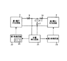
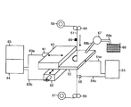
このワイヤ放電加工機は、電極として用いる導電性のワイヤ51と、ワイヤ51と加工対象物52との間に矩形の電圧パルスを印加する電圧印加回路53と、加工対象物52と電圧印加回路53とを接続する給電ケーブル54aと、ワイヤ51と電圧印加回路53とを接続する給電ケーブル54bおよび給電端子55と、ワイヤ51を加工対象物52側に供給する供給リール56と、供給されたワイヤ51を巻き取る巻取りリール57と、ワイヤ51の供給および巻取りを停止させるブレーキ58と、ワイヤ51を巻取りリール57に送る巻取りローラ59と、加工対象物52を固定するクロステーブル60と、所定のX軸方向にクロステーブル60を移動させるX軸モータ61とを備える。
【0004】
また、このワイヤ放電加工機は、X軸方向に直交するY軸方向にクロステーブル60を移動させるY軸モータ62と、モータ制御ケーブル63aおよび63bを介してX軸モータ61およびY軸モータ62を駆動するサーボ回路64と、サーボ回路64に制御信号を出力し、クロステーブル60および加工対象物52を移動させて加工位置を制御する制御回路65と、加工液が充填された加工液タンク66と、加工液タンク66から加工液を汲み出すポンプ67と、加工液タンク66からポンプ67に加工液を供給する加工液供給パイプ68aと、ポンプ67から加工対象物52側に加工液を供給する加工液供給パイプ68bと、ワイヤ51を加工対象物52側に供給するガイド69とを備える。
【0005】
このワイヤ放電加工機では、電圧印加回路53が、給電ケーブル54a,54bおよび給電端子55を介し、ワイヤ51と加工対象物52との間に矩形の電圧パルスを印加する。これにより、ワイヤ51と加工対象物52との間に放電が発生し、この放電によって加工対象物52の一部が除去される。そして、加工対象物52を移動させて所望の部分を除去することにより、加工対象物52を所望の形状に加工する。また、この放電では、加工対象物52の一部が除去されるとともに、ワイヤ51の表面も除去される。そして、ワイヤ51の同じ部分を使い続けると断線してしまう。そこで、ワイヤ放電加工機では、断線を防ぐため、ワイヤ51の放電が行われていない部分を加工対象物52側に順次供給し、放電が行われた部分を順次巻取りながら加工を行う。
【0006】
ワイヤ51の供給は、供給リール56によってブレーキ58およびガイド69を介して行われる。一方、ワイヤ51の巻取りは、巻取りリール57によって、巻取りローラ59を介して行われる。クロステーブル60は、加工対象物52を固定する。X軸モータ61およびY軸モータ62は、クロステーブル60を二次元的に移動させる。制御回路65およびサーボ回路64からなるNC装置は、X軸モータ61およびY軸モータ62を駆動してクロステーブル60および加工対象物52を移動させ、加工位置を制御する。また、加工液タンク66には、加工液として、たとえば、脱イオン水が充填されている。ポンプ67は、加工液供給パイプ68aを介して加工液タンク66の加工液を汲み出し、加工液供給パイプ68bを介して、その加工液を放電場に供給する。
【0007】
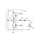
図24は、図23に示した電圧印加回路53の構成を示す図である。電圧印加回路53は、自電圧印加回路や電流経路に内在するインダクタンス73を介してワイヤ51を一端に接続した抵抗74と、抵抗74の他端を自スイッチの一端に接続したスイッチSW51と、スイッチSW51の他端を高電位側に接続し、加工対象物52を低電位側に接続した直流定電圧源75と、抵抗74の他端と加工対象物52との間に設けたスイッチSW52とを備える。直流定電圧源75は、所定の電圧を生成する。抵抗74は、放電電流を制限するために付加されている。スイッチSW51は、ワイヤ51と加工対象物52との間(以下、極間と呼ぶ)の電圧を上昇させるスイッチであり、スイッチSW52は、極間の電圧を0ボルトにするスイッチである。これらのスイッチとしては、たとえば電界効果トランジスタ(FET)を用いる。
【0008】
図25は、従来の電圧印加回路53の動作を示す図である。電圧印加回路53の動作では、まず、スイッチSW51がオフであってスイッチSW52がオンである状態から、スイッチSW51をオンにするとともにスイッチSW52をオフにすると、スイッチSW52の抵抗74側P51とスイッチSW52の加工対象物側P52との間の電圧が立ち上がり、極間の電圧が立ち上がる。極間の静電容量およびインダクタンス73の値は、抵抗74と比較して、十分小さいので、スイッチSW51がオンすると、極めて速いスピードで極間の電圧が立ち上がる。
【0009】
そして、後述する放電遅れ時間td経過後、すなわち電圧パルスの印加の途中で極間の放電が始まり、極間に放電電流が流れ始める。これにより、極間の電圧が下がる。その後、スイッチSW51をオフにするとともにスイッチSW52をオンにすると、P51−P52間の電圧および極間の電圧が0ボルトとなり、放電が停止し、放電電流が0アンペアとなる。電圧印加回路53は、この動作を所定周期で繰り返すことによって極間に断続的に放電を発生させる。
【0010】
図26は、従来の放電加工装置の放電遅れ時間と放電確率との関係を示す図である。図26に示すように、極間の電圧が最大値の10%を超えてから放電電流が所定値以上流れ始めるまでの放電遅れ時間tdは、放電を開始するために最低限必要な形成遅れ時間tfと、各放電ごとに確率的に長さがばらつく確率遅れ時間tsとを加算したものとなる。すなわち、各放電の放電遅れ時間tdは、極間の距離(以下、ギャップ間隔と呼ぶ)や極間に印加する電圧等の物理条件が同じであっても一定値に定まらず、所定の範囲でばらつく。
【0011】
図27は、従来の放電加工装置の放電遅れ時間,放電確率およびギャップ間隔の関係を示す図である。ここでは、極間に印加する電圧を80ボルトに固定し、ギャップ間隔を5マイクロ・メートル,8マイクロ・メートルおよび10マイクロ・メートルにそれぞれ設定した場合の放電遅れ時間tdを示している。図27に示すように、極間に印加する電圧を一定にし、ギャップ間隔を変化させた場合、ギャップ間隔が大きくなるほど放電遅れ時間tdが長くなる確率が高くなり、タイムアウトとなって結局放電しない場合も発生する。一方、ギャップ間隔が小さくなるほど放電遅れ時間tdが短くなる確率が高くなる。
【0012】
このギャップ間隔は、常に一定に保たれるとは限らず、ワイヤ51の振動や加工対象物52の凹凸によって平均値前後で値がばらつく。したがって、ギャップ間隔を小さくしすぎると、ギャップ間隔のばらつきによってワイヤ51と加工対象物52とがショートして放電が起こらない場合が発生する。また、ワイヤ51と加工対象物52とがショートすることによってワイヤ51の破損が発生する場合がある。このような不具合が起こらないように、ギャップ間隔は所定値以上確保しておく。また、ギャップ間隔を小さくして極間の電界強度を強くすると、同一箇所で連続して放電する集中放電が発生する確率が高くなる。
【0013】
図28は、従来の放電加工装置の放電遅れ時間,放電確率および印加電圧の関係を示す図である。ここでは、ギャップ間隔を5マイクロ・メートルに固定し、極間に印加する電圧を80ボルトおよび100ボルトにそれぞれ設定した場合の放電遅れ時間tdを示している。図28に示すように、ギャップ間隔を一定にし、極間に印加する電圧を変化させた場合、極間に印加する電圧が低くなるほど放電遅れ時間tdが長くなる確率が高くなり、タイムアウトとなって結局放電しない場合も発生する。一方、極間に印加する電圧が高くなるほど放電遅れ時間tdが短くなる確率が高くなる。また、極間に印加する電圧を高くして極間の電界強度を強くすると集中放電が発生する確率が高くなる。
【0014】
この電圧印加回路では、極間に対し、正方向の同じ極性の電圧印加のみを行う。このように、極間に対して同じ極性の電圧印加のみを行った場合、電気分解作用によって加工対象物52等が腐食劣化するという不具合がある。同じ極性の電圧印加のみを行う電圧印加回路53に代えて、正方向,負方向の電圧パルスを生成して極間に印加する電圧印加回路を用いることによって加工対象物52等の腐食劣化を低減することができる。
【0015】
図29は、従来の他の電圧印加回路の構成を示す図である。この電圧印加回路では、加工速度を向上させるとともに最終的な面精度を向上させるために、加工を複数段階に分け、最初に高速の荒加工を行い、その後、2回目以降の仕上げ加工を行っている。この電圧印加回路は、荒加工および仕上げ加工に用いる第1電圧印加回路100と、荒加工に用いる第2電圧印加回路101とを備える。第1電圧印加回路100は、所定の電圧を生成する直流定電圧源83と、直流定電圧源83の両端を自容量の両端に接続した容量85と、自第1電圧印加回路や電流経路に内在するインダクタンス98を介して加工対象物52を一端に接続した抵抗97と、直流定電圧源83の高電位側とワイヤ51との間に設けたFET87と、直流定電圧源83の低電位側とワイヤ51との間に設けたFET88と、直流定電圧源83の高電位側と抵抗97の他端との間に設けたFET89と、直流定電圧源83の低電位側と抵抗97の他端との間に設けたFET90とを備える。
【0016】
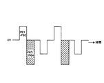
抵抗97は、放電電流を制限するために付加されている。FET87〜90は、フルブリッジ回路を構成し、FET87および90が同時にオンすることによってワイヤ51側に正方向の矩形の電圧パルスが印加される。また、FET88および89が同時にオンすることによってワイヤ51側に負方向の矩形の電圧パルスが印加される。また、FET88および90が同時にオンすることによってワイヤ51側の電圧が0ボルトとなる。第1電圧印加回路100は、FET87および90のオン、FET88および90のオン、FET88および89のオン、そしてFET88および90のオンを繰り返し、図30に示すような正方向および負方向の電圧パルス列を生成する。なお、図30は、FET88のワイヤ51側P61と抵抗97のFET90側P62との間の電圧を示している。仕上げ加工時は、第2電圧印加回路101を用いず、第1電圧印加回路100による正方向および負方向の電圧パルスを用いて加工を行う。
【0017】
一方、第2電圧印加回路101は、所定の電圧を生成する直流定電圧源84と、直流定電圧源84の両端を自容量の両端に接続した容量86と、自第2電圧印加回路や電流経路に内在するインダクタンス99を介して加工対象物52をカソードに接続したダイオード95と、ワイヤ51をアノードに接続したダイオード96と、直流定電圧源84の高電位側とダイオード95のアノードとの間に設けたFET91と、直流定電圧源84の低電位側とダイオード96のカソードとの間に設けたFET92と、直流定電圧源84の低電位側をアノードに接続し、ダイオード95のアノードを自ダイオードのカソードに接続したダイオード93と、直流定電圧源84の高電位側をカソードに接続し、ダイオード96のカソードを自ダイオードのアノードに接続したダイオード94とを備える。
【0018】
FET91および92が同時にオンすることによってワイヤ51側に負方向の矩形の電圧パルスが印加される。第2電圧印加回路101は、低インピーダンスかつ大容量であるので、高いピーク値の尖頭形の放電電流が流れる。FET91および92をオフにすると、インダクタンス94に蓄えられたエネルギーによってダイオード93および94を経由して帰還電流が流れる。荒加工時は、第2電圧印加回路101による高いピーク値の尖頭形の放電電流(主放電)を用いて高速加工を行う。しかし、主放電はピーク値が高いので、異常な放電が発生し、ワイヤ51の断線を引き起こす場合がある。この不具合を防ぐため、第1電圧印加回路100は、主放電を補助して正常に放電させる予備放電を発生させる。
【0019】
図31は、従来の荒加工時の動作を示す図である。なお、ここでは、P61−P62間の電圧を示すとともに、ダイオード96のカソード端子P63とダイオード95のアノード端子P64との間の電圧を斜線で示している。荒加工時においては、図31に示すように、第1電圧印加回路100による正方向の電圧印加の直後に第2電圧印加回路101による電圧印加を行う。さらに、第1電圧印加回路100による負方向の電圧印加の直後に第2電圧印加回路101による電圧印加を行ってもよい。第2電圧印加回路101は、極間に対し、負方向の同じ極性の電圧印加のみを行うが、極間にかかる電圧が低いので腐食劣化の影響は小さい。
【0020】
図32は、従来の荒加工時の印加電圧と放電電流との関係を示す図である。図32に示すように、荒加工時においては、第1電圧印加回路100による電圧印加を行い、極間に弱い予備放電が発生すると、できるだけ早く第2電圧印加回路101による電圧印加に切り替え、極間に尖頭形の強い主放電を発生させる。図示しない放電検出回路は、予備放電発生を検出し、図示しない制御回路に検出結果を通知する。
【0021】
図示しない制御回路は、予備放電が始まったことを示す検出結果の通知を受けると、第2電圧印加回路101を制御して主放電用の電圧印加を開始させるとともに、第1電圧印加回路100を制御して予備放電用の電圧印加を停止させる。予備放電が発生してから主放電用の電圧印加が始まるまでの電源切替時間txは、できる限り短くなるようにすることが望ましい。また、予備放電が発生してから次の予備放電を発生させる電圧印加を行うまでのパルス間隔を短くすることによって加工速度を上げることができるが、パルス間隔を短くするほど集中放電が発生しやすくなる。
【0022】
【発明が解決しようとする課題】
しかしながら、上述した技術によれば、矩形の電圧パルスを用いて放電を行うため、矩形の電圧パルスの電圧値が高い場合やギャップ間隔がばらついて小さくなった場合、極間の電界強度が所定値以上に高くなるので、集中放電が発生し、電極が破損する場合があるという問題点があった。特に、主放電および予備放電を行う場合は、集中放電が発生しやすくなり、また、主放電のエネルギーが大きいので、集中放電が発生すると電極の破損が大きくなる。また、矩形の電圧パルスの電圧値が低い場合やギャップ間隔がばらついて大きくなった場合、極間の電界強度が所定値以下に低くなるので、放電遅れ時間が長くなって加工スピードが遅くなり、さらに、タイムアウトとなって放電しない放電ミスが増加する場合があるという問題点があった。
【0023】
この発明は、上記に鑑みてなされたものであって、集中放電を低減して電極の破損を低減するとともに放電ミスを低減しつつ高速加工を行う放電加工装置を得ることを目的とする。
【0024】
【課題を解決するための手段】
上述した課題を解決し、目的を達成するために、この発明にかかる放電加工装置にあっては、加工対象物へ放電して該加工対象物を加工する電極と、該電極と加工対象物との間に電圧パルスを印加する電圧印加手段と、を備える放電加工装置において、前記電圧印加手段は、前記加工対象物と前記電極との間の距離が前記加工時の平均値である場合に、矩形電圧パルスが印加されたときの放電の形成遅れ時間に比して立上り時間が長く、該矩形電圧パルスと同じ電圧値まで立ち上がる電圧パルスを印加し、該印加される電圧パルスは、放電開始前に所定の電圧値まで急峻に立上り、所定の電圧値から前記矩形電圧パルスと同じ最高電圧値まで緩やかに立上るようにして、前記所定の電圧値を越えた後、前記最高電圧値に達する前に放電を発生させることを特徴とする。
【0025】
この発明によれば、電圧印加手段は、前記加工対象物と前記電極との間の距離が前記加工時の平均値である場合に、矩形電圧パルスが印加されたときの放電の形成遅れ時間に比して立上り時間が長く、該矩形電圧パルスと同じ電圧値まで立ち上がる電圧パルスを印加し、該印加される電圧パルスは、放電開始前に所定の電圧値まで急峻に立上り、所定の電圧値から前記矩形電圧パルスと同じ最高電圧値まで緩やかに立上るようにして、前記所定の電圧値を越えた後、前記最高電圧値に達する前に放電を発生させる。これにより、放電遅れ時間を短くすることができる。
【0028】
次の発明にかかる放電加工装置にあっては、前記電圧パルスの立上り時間が、0.1マイクロ秒以上かつ100マイクロ秒以下に設定されることを特徴とする。
【0029】
この発明によれば、前記電圧パルスの立上り時間が、0.1マイクロ秒以上かつ100マイクロ秒以下に設定されるため、ギャップ間隔に応じて、極間の電圧を放電可能な電圧値まで上昇させつつ、極間の電圧が集中放電を発生させる電圧値になる前に正常な放電を開始させることができる。
【0032】
次の発明にかかる放電加工装置にあっては、前記電圧印加手段が、両端間の電圧によって前記電圧パルスを生成する容量手段と、前記容量手段の両端間の電圧が所定値になるまで該容量手段に電流を供給する直流定電流源と、を有することを特徴とする。
【0033】
この発明によれば、容量手段が、両端間の電圧によって電圧パルスを生成し、直流定電流源が、容量手段の両端間の電圧が所定値になるまで該容量手段に電流を供給する。これにより、印加時間に比例して電圧値が上昇する電圧パルスを生成することができる。
【0040】
次の発明にかかる放電加工装置にあっては、前記第1の電圧が、0ボルト以上かつ100ボルト以下に設定され、前記第2の電圧が、60ボルト以上かつ300ボルト以下に設定されることを特徴とする。
【0041】
この発明によれば、第1の電圧が、0ボルト以上かつ100ボルト以下に設定され、第2の電圧が、60ボルト以上かつ300ボルト以下に設定されるため、ギャップ間隔に応じて、極間の電圧を放電可能な電圧値まで上昇させつつ、極間の電圧が集中放電を発生させる電圧値になる前に正常な放電を開始させることができる。
【0042】
【発明の実施の形態】
以下、この発明の実施の形態を、図面を参照して詳細に説明する。なお、この実施の形態によって、この発明が限定されるものではない。
【0043】
実施の形態1.
図1は、この発明の実施の形態1にかかる放電加工装置の概略構成を示す図である。この放電加工装置は、加工対象物1を加工する電極として導電性のワイヤ2を用いるワイヤ放電加工機である。ワイヤ2としては、たとえば、直径0.3ミリ・メートル〜0.03ミリ・メートルの銅線や黄銅線を用いる。このワイヤ放電加工装置は、図23に示した従来のワイヤ放電加工と同様に、図示しないNC装置、クロステーブル、X軸モータ、Y軸モータ、ワイヤ2の供給・巻取りを行う装置および加工液を供給する装置を備える。
【0044】
また、このワイヤ放電加工装置は、荒加工および仕上げ加工に用いる第1電圧印加回路3と、荒加工に用いる第2電圧印加回路4と、加工対象物1とワイヤ2との間(以下、極間と呼ぶ)の予備放電発生を検出する放電検出回路21と、放電検出回路21の検出結果に基づいて第1電圧印加回路3を制御する第1制御回路22と、放電検出回路21の検出結果に基づいて第2電圧印加回路4を制御する第2制御回路23とを備える。第1電圧印加回路3は、正方向および負方向の電圧パルスを生成して極間に印加し、仕上げ加工用の放電および荒加工用の予備放電を発生させる。
【0045】
第2電圧印加回路4は、負方向の電圧パルスを生成して極間に印加し、荒加工用の主放電を発生させる。放電検出回路21は、予備放電の発生を検出し、第1制御回路22および第2制御回路23に検出結果を通知する。第1制御回路22は、パルス間隔をカウントするタイマ24を有し、予備放電が始まったことを示す検出結果の通知を受けると、第1電圧印加回路3を制御して電圧印加を停止させるとともに、パルス間隔のカウントを開始する。そして、第1制御回路22は、パルス間隔のカウントが終了すると、第1電圧印加回路3を制御して、次の予備放電を発生させる電圧パルスを極間に印加させる。
【0046】
一方、第2制御回路23は、予備放電が始まったことを示す検出結果の通知を受けると、第2電圧印加回路4を制御して、主放電を発生させる電圧パルスを極間に印加させる。放電検出回路21、第2電圧印加回路4および第2制御回路23は、予備放電が開始してから、主放電を発生させる電圧パルスを印加するまでの電源切替時間ができるだけ短くなるように、素早く動作する。また、パルス間隔を短くすることによって加工速度を上げることができるが、パルス間隔を短くしすぎると集中放電が発生しやすくなるので、パルス間隔は、集中放電が発生しない所定値以上に設定される。
【0047】
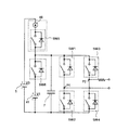
図2は、図1に示した第1電圧印加回路3および第2電圧印加回路4の概略構成を示す図である。第1電圧印加回路3は、所定の電圧V0を生成する直流定電圧源5と、直流定電圧源5の高電位側を一端に接続した抵抗6と、自第1電圧印加回路や電流経路に内在するインダクタンス9を介して加工対象物1を一端に接続した抵抗8と、抵抗6の他端と電極2との間に設けたスイッチSW1と、電極2と直流定電圧源5の低電位側との間に設けたスイッチSW2と、電極2と直流定電圧源5の低電位側との間に設けた容量7aと、抵抗6の他端と抵抗8の他端との間に設けたスイッチSW3と、抵抗6の他端と直流定電圧源5の低電位側との間に設けたスイッチSW4と、抵抗6の他端と直流定電圧源5の低電位側との間に設けた容量7bとを備える。
【0048】
抵抗8は、放電電流を制限するために付加されている。容量7aおよび7bとしては、第1電圧印加回路3が生成する電圧パルスの立上り時間に対して十分良い周波数特性を有するコンデンサを用いる。ここで、立上り時間とは、電圧パルスの絶対値が最大値の10%を超えてから最大値の90%に達するまでの時間をいう。スイッチSW1〜SW4としては、たとえば、FET等のトランジスタを用いる。スイッチSW1〜SW4は、フルブリッジ回路を構成し、スイッチSW1およびSW4がオンすることによってワイヤ2側に正方向の電圧パルスが印加される。また、スイッチSW2およびSW3がオンすることによってワイヤ2側に正方向の電圧パルスが印加される。
【0049】
一方、第2電圧印加回路4は、所定の電圧Vmを生成する直流定電圧源10と、直流定電圧源10の両端を自容量の両端に接続した容量11と、第2電圧印加回路4や電流経路に内在するインダクタンス16を介して加工対象物1をカソードに接続したダイオード13と、電極2をアノードに接続したダイオード12と、直流定電圧源10の高電位側とダイオード13のアノードとの間に設けたFET17と、直流定電圧源10の低電位側とダイオード12のカソードとの間に設けたFET18と、直流定電圧源10の低電位側をアノードに接続し、ダイオード13のアノードを自ダイオードのカソードに接続したダイオード15と、直流定電圧源10の高電位側をカソードに接続し、ダイオード12のカソードを自ダイオードのアノードに接続したダイオード14とを備える。
【0050】
FET17および18が同時にオンすることによってワイヤ2側に負方向の矩形の電圧パルスが印加される。第2電圧印加回路4は、低インピーダンスかつ大容量であるので、高いピーク値の尖頭形の放電電流が流れる。FET17および18をオフにすると、インダクタンス16に蓄えられたエネルギーによってダイオード14および15を経由して帰還電流が流れる。荒加工時は、第2電圧印加回路4による高いピーク値の尖頭形の放電電流(主放電)を用いて高速加工を行う。しかし、主放電はピーク値が高いので、異常な放電が発生し、ワイヤ2の断線を引き起こす場合がある。この不具合を防ぐため、第1電圧印加回路3は、主放電を補助して正常に放電させる予備放電を発生させる。
【0051】
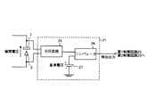
図3は、図1に示した放電検出回路21の概略構成を示す図である。放電検出回路21は、極間の電圧を分圧して分圧電圧を生成する分圧回路25と、分圧電圧との比較用の基準電圧を生成する直流定電圧源27と、分圧電圧と基準電圧とを比較し、比較結果を検出結果として出力するコンパレータ26とを備える。極間の電圧は、第1電圧印加回路3による電圧パルスの印加によって上昇するが、予備放電が開始するとともに下降する。分圧回路25は、極間の電圧を分圧して比較に適した大きさの分圧電圧を生成する。
【0052】
直流定電圧源27が生成する基準電圧は、予備放電開始前と予備放電開始後の分圧電圧を区別できるように、これらの値の中間の値に設定される。コンパレータ26は、分圧電圧と基準電圧とを比較し、予備放電開始前はハイレベルの信号を出力し、予備放電開始後、極間の電圧が下がり、分圧電圧が下がるとローレベルの信号を出力する。第1制御回路22および第2制御回路23は、コンパレータ26の出力信号がハイレベルからローレベルに変化した場合、予備放電が開始したと判断する。
【0053】
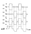
以上の構成において、実施の形態1の動作について図4〜図8を参照して説明する。図4は、実施の形態1にかかる第1電圧印加回路3の動作を示すタイミングチャートである。第1電圧印加回路3の動作では、極間に電圧パルスを印加する前にスイッチSW2およびSW4をオンにして容量7aおよび7bを放電しておく。また、スイッチSW1およびSW3をオフにしておく。正方向の電圧パルスを印加する場合は、スイッチSW1のオンおよびスイッチSW2のオフを同時に行う。これにより、容量7aの充電が始まり、スイッチSW2の電極2側P1と抵抗8のスイッチSW4側P2との間の電圧が上昇し、極間の電圧が上昇する。そして、スイッチSW1のオフおよびスイッチSW2のオンを同時に行うことによって正方向の電圧パルスの印加が終了する。
【0054】
また、負方向の電圧パルスを印加する場合は、スイッチSW3のオンおよびSW4のオフを同時に行う。これにより、容量7bの充電が始まり、P1−P2間の電圧が下降し、極間の電圧が下降する。そして、スイッチSW3のオフおよびスイッチSW4のオンを同時に行うことによって負方向の電圧パルスの印加が終了する。正方向および負方向の電圧パルスの印加が始まると、P1−P2間の電圧の絶対値は、直流定電圧源5が生成する電圧V0まで緩やかに上昇する。これらの電圧パルスは、立上りを鈍らせた「なまり波形(CR波形)」となる。この凸形状のCR波形の時定数は、容量7a,7bのキャパシタンスおよび抵抗6の抵抗値に応じて定まる。
【0055】
図5は、実施の形態1にかかる荒加工時の動作を示すタイミングチャートである。なお、ここでは、P1−P2間の電圧を示すとともに、ダイオード12のカソード端子P3とダイオード13のアノード端子P4との間の電圧を斜線で示している。荒加工時においては、図5に示すように、第1電圧印加回路3による正方向の電圧印加の直後に第2電圧印加回路4による電圧印加を行う。さらに、第1電圧印加回路3による負方向の電圧印加の直後に第2電圧印加回路4による電圧印加を行ってもよい。荒加工時においては、第1電圧印加回路3による電圧印加によって極間に弱い予備放電が発生すると、できるだけ早く第2電圧印加回路4による電圧印加に切り替えて極間に尖頭形の強い主放電を発生させる。予備放電が発生してから主放電用の電圧印加が始まるまでの電源切替時間txは、できる限り短くなるようにすることが望ましい。
【0056】
図6は、実施の形態1にかかる第1電圧印加回路3が生成する電圧パルスの波形を示す図である。なお、ここでは、正方向の電圧パルスを示しているが、負方向の電圧パルスも極性以外は同じものであると考えることができる。すなわち、第1電圧印加回路3が生成する電圧パルスと放電との関係は、絶対値で考えることができる。以下、特にことわらない限り、「電圧パルス」という場合は、正方向および負方向を含めた絶対値の電圧パルスを意味するものとする。
【0057】
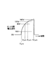
第1電圧印加回路3が生成する電圧パルスは、CR波形であって最大値まで緩やかに立ち上がる。電圧パルスの最大値は、極間の距離(以下、ギャップ間隔と呼ぶ)が、ワイヤ2の振動や加工対象物1の凹凸によって大きくなった場合も、高確率で放電を発生させることができる電圧値に設定される。この例では、第1電圧印加回路3が生成する電圧パルスは、最大値が160ボルトであって、最大値の10%である16ボルトを超えてから3マイクロ秒後に80ボルトとなり、5マイクロ秒後に120ボルトとなり、10マイクロ秒後に最大値160ボルトとなる。
【0058】
この電圧パルスの立上り時間trは、160ボルトの矩形電圧パルスを極間に印加した場合の形成遅れ時間に比して長い。この形成遅れ時間よりも短い立上り時間trでは、矩形波に近い波形となり、放電が始まる前に電圧値が十分高くなるので、集中放電の確率が高くなる。形成遅れ時間は、極間に印加する電圧やギャップ間隔に依存するが、ほぼ0.1マイクロ秒程度である。一方、立上り時間trをあまり長くすると所望の加工速度が得られなくなる。そこで、立上り時間trは、0.1マイクロ秒以上かつ100マイクロ秒以下に設定される。
【0059】
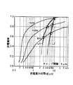
図7は、実施の形態1にかかる放電遅れ時間と放電確率との関係を示す図である。第1電圧印加回路3が生成するCR波形の電圧パルスを極間に印加した場合、この電圧パルスが最大値の10%を超えてからX時間経過時の放電確率は、その時点における電圧パルスの電圧値と同じ電圧値の矩形電圧パルスをX時間印加した場合の放電確率とほぼ等しい。図6の例では、電圧パルスが最大値の10%を超えてから3マイクロ秒経過時点の放電確率は、80ボルトの矩形電圧パルスを3マイクロ秒印加した場合の放電確率とほぼ一致し、5マイクロ秒経過時点の放電確率は、120ボルトの矩形電圧パルスを5マイクロ秒印加した場合の放電確率とほぼ一致し、10マイクロ秒経過時点の放電確率は、160ボルトの矩形電圧パルスを10マイクロ秒印加した場合の放電確率とほぼ一致する。
【0060】
そして、第1電圧印加回路3が生成するCR波形の電圧パルスを極間に印加した場合の放電遅れ時間tdがばらつく範囲は、矩形電圧パルスを印加した場合に比して狭まり、放電遅れ時間tdの平均値は短くなる(図7のL1参照)。また、ギャップ間隔がばらついて小さくなった場合は、集中放電を発生させる電圧値まで電圧パルスが上昇する前に放電遅確率が100%となる。図8は、実施の形態1にかかる放電遅れ時間,放電確率およびギャップ間隔の関係を示す図である。ここでは、ギャップ間隔を5マイクロ・メートル,8マイクロ・メートルおよび10マイクロ・メートルにそれぞれ設定した場合の放電遅れ時間tdを示している。図8に示すように、ギャップ間隔に関わらず、放電遅れ時間tdがばらつく範囲は、矩形電圧パルスを印加した場合に比して狭まる。また、タイムアウトする前に高確率で放電が行われる。
【0061】
前述したように、実施の形態1によれば、第1電圧印加回路3が、加工対象物1とワイヤ2との間の距離が加工時の平均値である場合に矩形電圧パルスが印加されたときの放電の形成遅れ時間に比して立上り時間trが長く、該矩形電圧パルスと同じ電圧値まで立ち上がる電圧パルスを加工対象物1とワイヤ2との間に印加して加工対象物1とワイヤ2との間に放電を発生させる。これにより、ギャップ間隔に応じて、極間の電圧を放電可能な電圧値まで上昇させつつ、極間の電圧が集中放電を発生させる電圧値になる前に正常な放電を開始させることができるため、集中放電を低減して電極の破損を低減するとともに放電ミスを低減しつつ高速加工を行うことができる。
【0062】
実施の形態2.
この発明の実施の形態2は、前述した実施の形態1において、CR波形の電圧パルスを生成する第1電圧印加回路3に代えて、印加時間に比例して電圧値が上昇する傾斜波形の電圧パルスを生成する第1電圧印加回路を設けたものである。図9は、この発明の実施の形態2にかかる第1電圧印加回路の概略構成を示す図である。なお、実施の形態1と同一構成の部分については図2と同一の符号を付している。
【0063】
この第1電圧印加回路は、実施の形態1の第1電圧印加回路3において、抵抗6に代えて、所定の電流をスイッチSW1およびSW3側に出力する直流定電流源31を設けたものである。この第1電圧印加回路では、スイッチSW1およびSW4がオンすることによってワイヤ2側に正方向の電圧パルスが印加される。また、スイッチSW2およびSW3がオンすることによってワイヤ2側に負方向の電圧パルスが印加される。なお、実際の回路では、直流定電流源31は、一つではなく、スイッチSW1と一体に設けられた直流定電流源、およびスイッチSW2と一体に設けられた直流定電流源の二つの直流定電流源を配置する。図10は、スイッチSW1および直流定電流源の概略構成を示す図である。
【0064】
スイッチSW1および直流定電流源は、直流定電圧源5の高電位側をドレイン端子に接続し、容量7aおよびスイッチSW2側をソース端子に接続したFET34と、FET34のドレイン端子とゲート端子との間に設けた容量32と、FET34のゲート端子を一端に接続した抵抗33とを備える。そして、抵抗33の他端とFET34のソース端子との間には、直流定電流源およびスイッチSW1を制御する信号電圧Vinが印加される。スイッチSW1がオンすることによって、直流定電流源による一定の電流が容量7aに流れ込む。容量7aの両端間の電圧は、V0に達するか、またはスイッチSW1がオフされるまで、時間に比例して上昇する。すなわち、容量7aの両端間の電圧を時間で微分した値は一定となる。この電圧によって正方向の電圧パルスが生成される。スイッチSW2および直流低電流源も同じ構成である。
【0065】
以上の構成において、実施の形態2の動作について図11〜図13を参照して説明する。図11は、実施の形態2にかかる第1電圧印加回路の動作を示すタイミングチャートである。実施の形態2の第1電圧印加回路は、実施の形態1の第1電圧印加回路3と基本的に同じ動作を行うが、CR波形の電圧パルスに代えて傾斜波形の電圧パルスを生成する部分が異なる。図12は、実施の形態2にかかる第1電圧印加回路が生成する電圧パルスの波形を示す図である。
【0066】
この第1電圧印加回路が生成する電圧パルスは、電圧値の時間変化率を一定に保ちつつ最大値まで直線的に電圧値を上昇させる傾斜波形を有する。この傾斜波形の電圧パルスは、同じ最大値を有するCR波形の電圧パルスに比して、電圧上昇中における同時点での電圧値が低くなる。従って、図13に示すように、傾斜波形の電圧パルスを印加した場合の放電遅れ時間の確率曲線L2は、CR波形の電圧パルスを印加した場合の放電遅れ時間の確率曲線L1の右側となる。すなわち、傾斜波形の電圧パルスを印加した場合の放電遅れ時間は、CR波形の電圧パルスを印加した場合の放電遅れ時間に比して長くなる確率が高くなる。
【0067】
しかし、最終的に到達する最大値が同じであれば、傾斜波形の電圧パルスを印加した場合の放電確率が100%になる時点と、CR波形の電圧パルスを印加した場合の放電確率が100%となる時点とは、ほぼ同一となる。したがって、傾斜波形の電圧パルスを印加した場合の放電遅れ時間のばらつきの範囲は、CR波形の電圧パルスを印加した場合の放電遅れ時間のばらつきの範囲に比して狭まる。なお、図12では、最大値に到達するとすぐに0ボルトになる三角波形が示されているが、最大値となったあと、その最大値を保つようにしてもよい。
【0068】
このように、電圧パルスとして所望の波形形状を選択することによって、放電遅れ時間のばらつきの範囲や放電遅れ時間の平均値を所望の値に設定することができる。前述したように、実施の形態2によれば、容量7aおよび7bが、両端間の電圧によって正方向および負方向の電圧パルスを生成し、直流定電流源31が、容量7a,7bの両端間の電圧が所定値になるまで容量7a,7bに一定の電流を供給する。これにより、印加時間に比例して電圧値が上昇する電圧パルスを生成することができるため、放電遅れ時間がばらつく範囲を狭めることができる。
【0069】
実施の形態3.
この発明の実施の形態3は、前述した実施の形態1において、0ボルトから最大値まで緩やかに立ち上がる電圧パルスを生成する第1電圧印加回路3に代えて、所定値まで急峻に立ち上がり、その後、最大値まで緩やかに立ち上がる電圧パルスを生成する第1電圧印加回路を設けたものである。図14は、この発明の実施の形態3にかかる第1電圧印加回路の概略構成を示す図である。なお、実施の形態1と同一構成の部分については図2と同一の符号を付している。
【0070】
この第1電圧印加回路は、実施の形態1の第1電圧印加回路3において、スイッチSW1,SW3と抵抗6との間にスイッチSW5を設け、スイッチSW5のスイッチSW1,SW3側と直流定電圧源5の低電位側との間に、所定の電圧V1を生成する直流定電圧源41およびスイッチSW6の直列回路を設け、容量7aおよび7bに代えて、スイッチSW5のスイッチSW1,SW3側と直流定電圧源5の低電位側との間に、容量7を設けたものである。スイッチSW5およびSW6は、スイッチSW1〜SW4と同じ構成である。直流定電圧源41は、直流定電圧源5の低電位側を自直流定電圧源の低電位側に接続し、スイッチSW6を高電位側に接続する。この第1電圧印加回路では、スイッチSW1,SW4およびSW5がオンすることによってワイヤ2側に正方向の電圧パルスが印加される。
【0071】
また、スイッチSW2,SW3およびSW5がオンすることによってワイヤ2側に負方向の電圧パルスが印加される。また、この第1電圧印加回路では、極間に対する電圧印加の前にスイッチSW6を閉じて容量7の両端間の電圧をV1にしておく。そして、スイッチSW5がオンするとともにスイッチSW6がオフすることによって、容量7の両端間の電圧が緩やかにV0まで上昇する。この電圧によって正方向および負方向の電圧パルスが生成される。すなわち、2段階に電圧値が立ち上がる電圧パルスが生成される。極間に対する電圧印加のあとは、スイッチSW5がオフするとともにスイッチSW6がオンし、容量7の両端間の電圧がV1に戻る。
【0072】
直流定電圧源41が生成する電圧V1は、電圧V0に比して低く設定される。詳細には、電圧V0は、60ボルト〜300ボルトに設定され、電圧V1は、0ボルト〜100ボルトに設定される。この放電加工装置では、放電が生じている場合の電極間の電圧(アーク電圧)が15ボルト〜20ボルト程度となる。また、極間に50ボルト程度以上の最低印加電圧を印加しなければ放電が発生しない。アーク電圧や最低印加電圧は、電極,ギャップ間隔および加工液等の条件によって変化する。
【0073】
放電形成に寄与しない電圧を印加するのは時間の無駄となり、加工スピードを下げる要因となるので、望ましくは、電圧V1を最低印加電圧50ボルト程度またはそれ以上に設定する。一方、電圧V1を高くしすぎると、集中放電の可能性が高くなるので、100ボルト以下に設定する。電圧V0については、ギャップ間隔がばらついて大きくなっても放電を可能とし、かつ、集中放電を低減するために、60ボルト〜300ボルトに設定する。
【0074】
以上の構成において、実施の形態3の動作について図15〜図17を参照して説明する。図15は、実施の形態3にかかる第1電圧印加回路の動作を示すタイミングチャートである。実施の形態3の第1電圧印加回路は、実施の形態1の第1電圧印加回路3と基本的に同じ動作を行うが、0ボルトから緩やかに立ち上がる電圧パルスに代えて、電圧V1まで急峻に立ち上がり、その後、電圧V0まで緩やかに立ち上がる2段階の電圧パルスを生成する部分が異なる。また、スイッチSW1およびSW3がオフ状態の場合に、スイッチSW5がオフ状態となり、スイッチSW6がオン状態となる。そして、スイッチSW1またはSW3がオンするとともに、スイッチSW5がオンし、スイッチSW6がオフする。
【0075】
図16は、実施の形態3にかかる第1電圧印加回路が生成する電圧パルスの波形を示す図である。この第1電圧印加回路が生成する電圧パルスは、図6に示した実施の形態1の電圧パルスに比して、V1まで電圧を上昇させる時間を節約することができる。これにより、図17に示すように、実施の形態3の電圧パルスを用いた場合の放電遅れ時間の確率曲線L3は、実施の形態1の電圧パルスを用いた場合の放電遅れ時間の確率曲線L1に比して左側となる。すなわち、実施の形態3の電圧パルスを用いた場合の放電遅れ時間は、実施の形態1の電圧パルスを用いた場合の放電遅れ時間に比して短くなる確率が高くなる。
【0076】
前述したように、実施の形態3によれば、直流定電圧源41が、電圧V1を生成し、電圧パルスを電圧V1まで立ち上げ、直流定電圧源5が、電圧V1に比して高い電圧V0を生成し、電圧パルスを電圧V1から電圧V0まで緩やかに立ち上げる。これにより、まず、電圧V1まで電圧パルスを急峻に立ち上げ、その後、電圧V0まで緩やかに電圧パルスを立ち上げることができるため、放電遅れ時間を短くすることができる。
【0077】
実施の形態4.
前述した実施の形態3では、二つの直流定電圧源によって、2段階の電圧パルスを生成した。この発明の実施の形態4は、一つの直流定電圧源によって実施の形態3と同様の電圧パルスを生成するものである。図18は、この発明の実施の形態4にかかる第1電圧印加回路の概略構成を示す図である。なお、実施の形態1と同一構成の部分については図2と同一の符号を付している。
【0078】
この第1電圧印加回路は、実施の形態1の第1電圧印加回路3において、抵抗6と並列にツェナーダイオード43を設けたものである。ツェナーダイオード43は、両端の電圧が(V0−V1)以上である場合にツェナー効果によって導通する。スイッチSW1またはSW3がオンすると、ツェナーダイオード43の両端に(V0−V1)以上の電圧がかかり、ツェナーダイオード43が導通する。これにより、電圧パルスは電圧V1まで急峻に立ち上がる。
【0079】
電圧パルスが電圧V1を超えるとツェナーダイオード43が導通しなくなり、抵抗6の抵抗値およびコンデンサ7a,7bのキャパシタンスによって定まる時定数のCR波形に従って電圧が緩やかに上昇する。これにより、この第1電圧印加回路は、図19に示すように、実施の形態3と同様の電圧パルスを生成する。前述したように、実施の形態4によれば、一つの直流定電圧源5を用いた簡単な回路によって実施の形態3と同様の2段階の電圧パルスを生成することができる。
【0080】
実施の形態5.
この発明の実施の形態5は、前述した実施の形態3において、電圧V1まで急峻に立ち上がったあと、電圧V0までCR波形に従って立ち上がる電圧パルスを生成する第1電圧印加回路に代えて、電圧V1まで急峻に立ち上がったあと、電圧V0まで傾斜波形に従って立ち上がる電圧パルスを生成する第1電圧印加回路を設けたものである。図20は、この発明の実施の形態5にかかる第1電圧印加回路の概略構成を示す図である。なお、実施の形態3と同一構成の部分については図14同一の符号を付している。
【0081】
この第1電圧印加回路は、実施の形態3の第1電圧印加回路において、抵抗6に代えて、所定の電流をスイッチSW5側に出力する直流定電流源46を設けたものである。スイッチSW5および直流定電流源46は、図10に示した実施の形態2のスイッチSW1および直流定電流源と同様に構成することができる。この第1電圧印加回路では、スイッチSW1,SW4およびSW5がオンすることによってワイヤ2側に正方向の電圧パルスが印加される。また、スイッチSW2,SW3およびSW5がオンすることによってワイヤ2側に負方向の電圧パルスが印加される。また、この第1電圧印加回路では、極間に対する電圧印加の前にスイッチSW6を閉じて容量7の両端間の電圧をV1にしておく。
【0082】
そして、スイッチSW5がオンするとともにスイッチSW6がオフすることによって、直流定電流源46による一定の電流が容量7に流れ込み、容量7の両端間の電圧が時間に比例して上昇する。容量7の両端間の電圧によって正方向および負方向の電圧パルスが生成される。すなわち、電圧が2段階に立ち上がる電圧パルスが生成される。極間に対する電圧印加のあとは、スイッチSW5がオフするとともにスイッチSW6がオンし、容量7の両端間の電圧がV1に戻る。
【0083】
以上の構成において、実施の形態5の動作について図21および図22を参照して説明する。図21は、実施の形態5にかかる第1電圧印加回路の動作を示すタイミングチャートである。実施の形態5の第1電圧印加回路は、実施の形態3の第1電圧印加回路と基本的に同じ動作を行うが、電圧V1まで立ち上がったあと、CR波形ではなく、図22に示すような傾斜波形に従って電圧V0まで立ち上がるという部分が異なる。前述したように、実施の形態5によれば、電圧パルスが電圧V1から電圧V0に立ち上がる波形を傾斜波形にすることができる。
【0084】
なお、前述した実施の形態1〜実施の形態5では、ワイヤ放電加工機を例に挙げたが、前述した実施の形態1〜実施の形態5の第1電圧印加回路および第2電圧印加回路を型彫放電加工機に用いてもよく、同様の効果を得ることができる。
【0085】
【発明の効果】
以上説明したとおり、この発明によれば、電圧印加手段は、前記加工対象物と前記電極との間の距離が前記加工時の平均値である場合に、矩形電圧パルスが印加されたときの放電の形成遅れ時間に比して立上り時間が長く、該矩形電圧パルスと同じ電圧値まで立ち上がる電圧パルスを印加し、該印加される電圧パルスは、放電開始前に所定の電圧値まで急峻に立上り、所定の電圧値から前記矩形電圧パルスと同じ最高電圧値まで緩やかに立上るようにして、前記所定の電圧値を越えた後、前記最高電圧値に達する前に放電を発生させる。これにより、放電遅れ時間を短くすることができる、という効果を奏する。
【0087】
次の発明によれば、前記電圧パルスの立上り時間が、0.1マイクロ秒以上かつ100マイクロ秒以下に設定されるため、ギャップ間隔に応じて、極間の電圧を放電可能な電圧値まで上昇させつつ、極間の電圧が集中放電を発生させる電圧値になる前に正常な放電を開始させることができるため、集中放電を低減して電極の破損を低減するとともに放電ミスを低減しつつ高速加工を行うことができる、という効果を奏する。
【0089】
次の発明によれば、容量手段が、両端間の電圧によって電圧パルスを生成し、直流定電流源が、容量手段の両端間の電圧が所定値になるまで該容量手段に電流を供給する。これにより、印加時間に比例して電圧値が上昇する電圧パルスを生成することができるため、放電遅れ時間がばらつく範囲を狭めることができる、という効果を奏する。
【0093】
次の発明によれば、第1の電圧が、0ボルト以上かつ100ボルト以下に設定され、第2の電圧が、60ボルト以上かつ300ボルト以下に設定されるため、ギャップ間隔に応じて、極間の電圧を放電可能な電圧値まで上昇させつつ、極間の電圧が集中放電を発生させる電圧値になる前に正常な放電を開始させることができるため、集中放電を低減して電極の破損を低減するとともに放電ミスを低減しつつ高速加工を行うことができる、という効果を奏する。
【図面の簡単な説明】
【図1】 この発明の実施の形態1にかかる放電加工装置の概略構成を示す図である。
【図2】 図1に示した第1電圧印加回路および第2電圧印加回路の概略構成を示す図である。
【図3】 図1に示した放電検出回路の概略構成を示す図である。
【図4】 実施の形態1にかかる第1電圧印加回路の動作を示すタイミングチャートである。
【図5】 実施の形態1にかかる荒加工時の動作を示すタイミングチャートである。
【図6】 実施の形態1にかかる第1電圧印加回路の電圧波形を示す図である。
【図7】 実施の形態1にかかる放電遅れ時間と放電確率との関係を示す図である。
【図8】 実施の形態1にかかる放電遅れ時間,放電確率およびギャップ間隔の関係を示す図である。
【図9】 この発明の実施の形態2にかかる第1電圧印加回路の概略構成を示す図である。
【図10】 図9に示した直流定電流源およびスイッチの概略構成を示す図である。
【図11】 実施の形態2にかかる第1電圧印加回路の動作を示すタイミングチャートである。
【図12】 実施の形態2にかかる第1電圧印加回路の電圧波形を示す図である。
【図13】 実施の形態2にかかる放電遅れ時間と放電確率との関係を示す図である。
【図14】 この発明の実施の形態3にかかる第1電圧印加回路の概略構成を示す図である。
【図15】 実施の形態3にかかる第1電圧印加回路の動作を示すタイミングチャートである。
【図16】 実施の形態3にかかる第1電圧印加回路の電圧波形を示す図である。
【図17】 実施の形態3にかかる放電遅れ時間と放電確率との関係を示す図である。
【図18】 この発明の実施の形態4にかかる第1電圧印加回路の概略構成を示す図である。
【図19】 実施の形態4にかかる第1電圧印加回路の動作を示すタイミングチャートである。
【図20】 この発明の実施の形態5にかかる第1電圧印加回路の概略構成を示す図である。
【図21】 実施の形態5にかかる第1電圧印加回路の動作を示すタイミングチャートである。
【図22】 実施の形態5にかかる第1電圧印加回路の電圧波形を示す図である。
【図23】 従来の放電加工装置の構成を示す概観図である。
【図24】 図23に示した電圧印加回路の構成を示す図である。
【図25】 従来の電圧印加回路の動作を示す図である。
【図26】 従来の放電加工装置の放電遅れ時間と放電確率との関係を示す図である。
【図27】 従来の放電加工装置の放電遅れ時間,放電確率およびギャップ間隔の関係を示す図である。
【図28】 従来の放電加工装置の放電遅れ時間,放電確率および印加電圧の関係を示す図である。
【図29】 従来の他の電圧印加回路の構成を示す図である。
【図30】 従来の仕上げ加工時の動作を示す図である。
【図31】 従来の荒加工時の動作を示す図である。
【図32】 従来の荒加工時の印加電圧と放電電流との関係を示す図である。
【符号の説明】
1 加工対象物、2 ワイヤ、3 第1電圧印加回路、4 第2電圧印加回路、5,10,27,41 直流定電圧源、6,8 抵抗、7,7a,7b,11容量、12〜15 ダイオード、21 放電検出回路、22 第1制御回路、23 第2制御回路、24 タイマ、25 分圧回路、26 コンパレータ、31,46 直流定電流源、SW1〜SW6 スイッチ。[0001]
BACKGROUND OF THE INVENTION
The present invention relates to an electric discharge machining apparatus for machining an object to be machined by generating an electric discharge between the workpiece and an electrode, and more particularly to an electric discharge machining apparatus for performing high-speed machining.
[0002]
[Prior art]
As a conventional electric discharge machining apparatus, for example, a wire electric discharge machine for performing wire electric discharge machining and a die electric discharge machine for performing die electric discharge machining are known. In wire electric discharge machining, machining is performed using a conductive wire as an electrode, and in die-sinking electric discharge machining, machining is performed using electrodes having various shapes. FIG. 23 is a schematic view showing a configuration of a conventional wire electric discharge machine.
[0003]
The wire electric discharge machine includes a
[0004]
The wire electric discharge machine also includes a Y-
[0005]
In this wire electric discharge machine, the
[0006]
The supply of the
[0007]
FIG. 24 is a diagram showing the configuration of the
[0008]
FIG. 25 is a diagram illustrating the operation of the conventional
[0009]
Then, after the discharge delay time td, which will be described later, e.g., during the application of the voltage pulse, the discharge between the electrodes starts, and the discharge current starts to flow between the electrodes. As a result, the voltage between the electrodes decreases. Thereafter, when the switch SW51 is turned off and the switch SW52 is turned on, the voltage between P51 and P52 and the voltage between the electrodes become 0 volts, the discharge is stopped, and the discharge current becomes 0 amperes. The
[0010]
FIG. 26 is a diagram showing the relationship between the discharge delay time and the discharge probability of the conventional electric discharge machining apparatus. As shown in FIG. 26, the discharge delay time td from when the voltage between the electrodes exceeds 10% of the maximum value until the discharge current starts to flow more than a predetermined value is the minimum formation delay time necessary for starting discharge. It is obtained by adding tf and a probability delay time ts whose length varies stochastically for each discharge. That is, the discharge delay time td of each discharge is not determined to be a constant value even if the physical conditions such as the distance between the electrodes (hereinafter referred to as the gap interval) and the voltage applied between the electrodes are the same, and within a predetermined range. It varies.
[0011]
FIG. 27 is a diagram illustrating the relationship between the discharge delay time, the discharge probability, and the gap interval of the conventional electric discharge machining apparatus. Here, the discharge delay time td is shown when the voltage applied between the electrodes is fixed at 80 volts and the gap interval is set to 5 micrometers, 8 micrometers, and 10 micrometers, respectively. As shown in FIG. 27, when the voltage applied between the electrodes is kept constant and the gap interval is changed, the probability that the discharge delay time td becomes longer as the gap interval becomes larger, and the discharge does not occur due to timeout. Also occurs. On the other hand, the smaller the gap interval, the higher the probability that the discharge delay time td will be shortened.
[0012]
The gap interval is not always kept constant, and the value varies around the average value due to the vibration of the
[0013]
FIG. 28 is a diagram showing the relationship between the discharge delay time, discharge probability, and applied voltage of a conventional electric discharge machining apparatus. Here, the discharge delay time td is shown when the gap interval is fixed to 5 micrometers and the voltage applied between the electrodes is set to 80 volts and 100 volts, respectively. As shown in FIG. 28, when the gap interval is fixed and the voltage applied between the poles is changed, the probability that the discharge delay time td becomes longer as the voltage applied between the poles decreases, resulting in a timeout. In some cases, the battery does not discharge after all. On the other hand, the higher the voltage applied between the electrodes, the higher the probability that the discharge delay time td is shortened. Further, when the voltage applied between the electrodes is increased to increase the electric field strength between the electrodes, the probability of occurrence of concentrated discharge increases.
[0014]
In this voltage application circuit, only voltage application with the same polarity in the positive direction is performed between the electrodes. Thus, when only the voltage application of the same polarity is performed between the electrodes, there is a problem that the
[0015]
FIG. 29 is a diagram showing the configuration of another conventional voltage application circuit. In this voltage application circuit, in order to increase the processing speed and improve the final surface accuracy, the processing is divided into a plurality of stages, first high-speed roughing is performed, and then the second and subsequent finishing processing is performed. Yes. This voltage application circuit includes a first
[0016]
A
[0017]
On the other hand, the second
[0018]
When the
[0019]
FIG. 31 is a diagram illustrating an operation during conventional roughing. Here, the voltage between P61 and P62 is shown, and the voltage between the cathode terminal P63 of the
[0020]
FIG. 32 is a diagram showing the relationship between applied voltage and discharge current during conventional roughing. As shown in FIG. 32, during rough machining, voltage application by the first
[0021]
When the control circuit (not shown) receives the notification of the detection result indicating that the preliminary discharge has started, the control circuit controls the second
[0022]
[Problems to be solved by the invention]
However, according to the technique described above, since discharge is performed using rectangular voltage pulses, when the voltage value of the rectangular voltage pulses is high or the gap interval varies and decreases, the electric field strength between the electrodes is a predetermined value. Since it becomes higher than the above, there is a problem that concentrated discharge occurs and the electrode may be damaged. In particular, when main discharge and preliminary discharge are performed, concentrated discharge is likely to occur, and the energy of the main discharge is large, so that when the concentrated discharge occurs, the electrode is greatly damaged. In addition, when the voltage value of the rectangular voltage pulse is low or when the gap interval varies and becomes large, the electric field strength between the electrodes becomes lower than a predetermined value, so that the discharge delay time becomes long and the processing speed becomes slow, Furthermore, there has been a problem that discharge errors that do not discharge due to timeout may increase.
[0023]
The present invention has been made in view of the above, and an object of the present invention is to obtain an electric discharge machining apparatus that performs high-speed machining while reducing concentrated discharge to reduce electrode breakage and reducing electric discharge mistakes.
[0024]
[Means for Solving the Problems]
In order to solve the above-described problems and achieve the object, in the electric discharge machining apparatus according to the present invention, an electrode that discharges the workpiece and processes the workpiece, the electrode and the workpiece In the electric discharge machining apparatus comprising a voltage application means for applying a voltage pulse between the voltage application means, when the distance between the workpiece and the electrode is an average value during the machining, Rise time is longer than the formation delay time of discharge when a rectangular voltage pulse is applied, a voltage pulse that rises to the same voltage value as the rectangular voltage pulse is applied, and the applied voltage pulse is Before starting discharge It rises steeply to a predetermined voltage value and rises gently from the predetermined voltage value to the same maximum voltage value as the rectangular voltage pulse. Thus, after the predetermined voltage value is exceeded, the discharge is generated before the maximum voltage value is reached. It is characterized by that.
[0025]
According to the present invention, the voltage application means is configured to provide a discharge formation delay time when a rectangular voltage pulse is applied when the distance between the workpiece and the electrode is an average value during the machining. The rise time is longer than that, and a voltage pulse that rises to the same voltage value as the rectangular voltage pulse is applied. Before starting discharge It rises steeply to a predetermined voltage value and rises gently from the predetermined voltage value to the same maximum voltage value as the rectangular voltage pulse. Thus, after the predetermined voltage value is exceeded, the discharge is generated before the maximum voltage value is reached. . Thereby, the discharge delay time can be shortened.
[0028]
In the electric discharge machining apparatus according to the next invention, the rising time of the voltage pulse is set to 0.1 microsecond or more and 100 microsecond or less.
[0029]
According to the present invention, since the rise time of the voltage pulse is set to 0.1 microsecond or more and 100 microsecond or less, the voltage between the electrodes is increased to a dischargeable voltage value according to the gap interval. However, normal discharge can be started before the voltage between the electrodes reaches a voltage value that causes concentrated discharge.
[0032]
In the electric discharge machining apparatus according to the next invention, the voltage application means generates the voltage pulse by the voltage between both ends, and the capacity until the voltage between both ends of the capacitance means reaches a predetermined value. And a DC constant current source for supplying a current to the means.
[0033]
According to the present invention, the capacity means generates a voltage pulse by the voltage across both ends, and the DC constant current source supplies current to the capacity means until the voltage across the capacity means reaches a predetermined value. Thereby, a voltage pulse whose voltage value increases in proportion to the application time can be generated.
[0040]
In the electric discharge machining apparatus according to the next invention, the first voltage is set to 0 to 100 volts and the second voltage is set to 60 to 300 volts. It is characterized by.
[0041]
According to the present invention, the first voltage is set to 0 V or more and 100 V or less, and the second voltage is set to 60 V or more and 300 V or less. The normal discharge can be started before the voltage between the electrodes reaches a voltage value that causes a concentrated discharge.
[0042]
DETAILED DESCRIPTION OF THE INVENTION
Hereinafter, embodiments of the present invention will be described in detail with reference to the drawings. In addition, this invention is not limited by this embodiment.
[0043]
FIG. 1 is a diagram showing a schematic configuration of an electric discharge machining apparatus according to
[0044]
The wire electric discharge machining apparatus includes a first
[0045]
The second
[0046]
On the other hand, when receiving the notification of the detection result indicating that the preliminary discharge has started, the
[0047]
FIG. 2 is a diagram showing a schematic configuration of the first
[0048]
The
[0049]
On the other hand, the second
[0050]
When
[0051]
FIG. 3 is a diagram showing a schematic configuration of the
[0052]
The reference voltage generated by the DC
[0053]
With the above configuration, the operation of the first embodiment will be described with reference to FIGS. FIG. 4 is a timing chart illustrating the operation of the first
[0054]
When applying a voltage pulse in the negative direction, the switch SW3 is turned on and the switch SW4 is turned off simultaneously. As a result, charging of the
[0055]
FIG. 5 is a timing chart illustrating an operation during rough machining according to the first embodiment. Here, the voltage between P1 and P2 is shown, and the voltage between the cathode terminal P3 of the
[0056]
FIG. 6 is a diagram illustrating a waveform of a voltage pulse generated by the first
[0057]
The voltage pulse generated by the first
[0058]
The rise time tr of the voltage pulse is longer than the formation delay time when a rectangular voltage pulse of 160 volts is applied between the electrodes. At the rise time tr shorter than the formation delay time, the waveform is close to a rectangular wave, and the voltage value becomes sufficiently high before the discharge starts, so that the probability of concentrated discharge increases. The formation delay time depends on the voltage applied between the electrodes and the gap interval, but is about 0.1 microsecond. On the other hand, if the rise time tr is too long, a desired processing speed cannot be obtained. Therefore, the rise time tr is set to 0.1 microsecond or more and 100 microsecond or less.
[0059]
FIG. 7 is a diagram illustrating the relationship between the discharge delay time and the discharge probability according to the first embodiment. When a voltage pulse having a CR waveform generated by the first
[0060]
The range in which the discharge delay time td varies when a voltage pulse having a CR waveform generated by the first
[0061]
As described above, according to the first embodiment, the rectangular voltage pulse is applied to the first
[0062]
In
[0063]
This first voltage application circuit is provided with a DC constant
[0064]
The switch SW1 and the DC constant current source include a
[0065]
In the above configuration, the operation of the second embodiment will be described with reference to FIGS. FIG. 11 is a timing chart illustrating the operation of the first voltage application circuit according to the second embodiment. The first voltage application circuit of the second embodiment performs basically the same operation as the first
[0066]
The voltage pulse generated by the first voltage application circuit has a ramp waveform that linearly increases the voltage value to the maximum value while keeping the time change rate of the voltage value constant. The voltage pulse of this ramp waveform has a lower voltage value at the same point during the voltage rise than the voltage pulse of the CR waveform having the same maximum value. Therefore, as shown in FIG. 13, the discharge delay time probability curve L2 when a ramp waveform voltage pulse is applied is to the right of the discharge delay time probability curve L1 when a CR waveform voltage pulse is applied. That is, there is a higher probability that the discharge delay time when the voltage pulse having the ramp waveform is applied is longer than the discharge delay time when the voltage pulse having the CR waveform is applied.
[0067]
However, if the maximum value finally reached is the same, the discharge probability when the ramp waveform voltage pulse is applied becomes 100% and the discharge probability when the CR waveform voltage pulse is applied is 100%. Is almost the same. Therefore, the range of variation in the discharge delay time when a voltage pulse having a ramp waveform is applied is narrower than the range of variation in the discharge delay time when a voltage pulse having a CR waveform is applied. FIG. 12 shows a triangular waveform that becomes 0 volts as soon as the maximum value is reached. However, the maximum value may be maintained after the maximum value is reached.
[0068]
Thus, by selecting a desired waveform shape as the voltage pulse, the range of variation in the discharge delay time and the average value of the discharge delay time can be set to desired values. As described above, according to the second embodiment, the
[0069]
In
[0070]
This first voltage application circuit is the same as the first
[0071]
Further, when the switches SW2, SW3 and SW5 are turned on, a negative voltage pulse is applied to the
[0072]
The voltage V1 generated by the DC
[0073]
Applying a voltage that does not contribute to discharge formation is a waste of time and causes a reduction in processing speed. Therefore, the voltage V1 is preferably set to a minimum applied voltage of about 50 volts or more. On the other hand, if the voltage V1 is too high, the possibility of concentrated discharge increases, so it is set to 100 volts or less. The voltage V0 is set to 60 to 300 volts in order to enable discharge even when the gap interval varies and becomes large and to reduce concentrated discharge.
[0074]
With the above configuration, the operation of the third embodiment will be described with reference to FIGS. FIG. 15 is a timing chart illustrating the operation of the first voltage application circuit according to the third embodiment. The first voltage application circuit of the third embodiment performs basically the same operation as that of the first
[0075]
FIG. 16 is a diagram illustrating a waveform of a voltage pulse generated by the first voltage application circuit according to the third embodiment. Compared with the voltage pulse of the first embodiment shown in FIG. 6, the voltage pulse generated by the first voltage application circuit can save time for raising the voltage to V1. Accordingly, as shown in FIG. 17, the probability curve L3 of the discharge delay time when the voltage pulse of the third embodiment is used is the probability curve L1 of the discharge delay time when the voltage pulse of the first embodiment is used. Compared to the left side. That is, the discharge delay time when the voltage pulse of the third embodiment is used is more likely to be shorter than the discharge delay time when the voltage pulse of the first embodiment is used.
[0076]
As described above, according to the third embodiment, the DC
[0077]
In
[0078]
This first voltage application circuit is obtained by providing a
[0079]
When the voltage pulse exceeds the voltage V1, the
[0080]
In the fifth embodiment of the present invention, instead of the first voltage application circuit that generates a voltage pulse that rises steeply up to the voltage V1 and then rises up to the voltage V0 according to the CR waveform in the third embodiment described above, the voltage V1 is used. A first voltage application circuit is provided that generates a voltage pulse that rises steeply and then rises according to a ramp waveform to a voltage V0. FIG. 20 is a diagram showing a schematic configuration of the first voltage applying circuit according to the fifth embodiment of the present invention. Note that the same reference numerals as those in FIG. 14 denote the same components as those in the third embodiment.
[0081]
This first voltage application circuit is provided with a DC constant
[0082]
When the switch SW5 is turned on and the switch SW6 is turned off, a constant current from the DC constant
[0083]
With the above configuration, the operation of the fifth embodiment will be described with reference to FIG. 21 and FIG. FIG. 21 is a timing chart illustrating the operation of the first voltage application circuit according to the fifth embodiment. The first voltage application circuit of the fifth embodiment performs basically the same operation as the first voltage application circuit of the third embodiment. However, after rising to the voltage V1, not the CR waveform but the one shown in FIG. The part that rises to the voltage V0 according to the ramp waveform is different. As described above, according to the fifth embodiment, the waveform in which the voltage pulse rises from the voltage V1 to the voltage V0 can be changed to an inclined waveform.
[0084]
In the above-described first to fifth embodiments, the wire electric discharge machine is taken as an example. However, the first voltage application circuit and the second voltage application circuit of the first to fifth embodiments described above are used. You may use for a die-sinking electric discharge machine and can acquire the same effect.
[0085]
【The invention's effect】
As described above, according to the present invention, the voltage application unit is configured to discharge when a rectangular voltage pulse is applied when the distance between the workpiece and the electrode is an average value during the processing. The rise time is longer than the formation delay time of the voltage pulse applied to rise to the same voltage value as the rectangular voltage pulse, the applied voltage pulse, Before starting discharge It rises steeply to a predetermined voltage value and rises gently from the predetermined voltage value to the same maximum voltage value as the rectangular voltage pulse. Thus, after the predetermined voltage value is exceeded, the discharge is generated before the maximum voltage value is reached. . Thereby, there is an effect that the discharge delay time can be shortened.
[0087]
According to the next invention, since the rise time of the voltage pulse is set to 0.1 microsecond or more and 100 microsecond or less, the voltage between the electrodes rises to a voltage value that can be discharged according to the gap interval. Therefore, normal discharge can be started before the voltage between the electrodes reaches the voltage value that causes concentrated discharge, so that concentrated discharge is reduced to reduce electrode damage and high speed while reducing discharge mistakes. There exists an effect that it can process.
[0089]
According to the next invention, the capacity means generates a voltage pulse according to the voltage between both ends, and the DC constant current source supplies current to the capacity means until the voltage between both ends of the capacity means reaches a predetermined value. As a result, a voltage pulse whose voltage value increases in proportion to the application time can be generated, so that the range in which the discharge delay time varies can be narrowed.
[0093]
According to the next invention, the first voltage is set to 0 to 100 volts and the second voltage is set to 60 to 300 volts. Since the normal voltage can be started before the voltage between the electrodes reaches the voltage value that causes the concentrated discharge while increasing the voltage between them to a dischargeable voltage value, the concentrated discharge is reduced and the electrode is damaged. As a result, it is possible to perform high-speed machining while reducing discharge mistakes.
[Brief description of the drawings]
FIG. 1 is a diagram showing a schematic configuration of an electric discharge machining apparatus according to a first embodiment of the present invention.
FIG. 2 is a diagram showing a schematic configuration of a first voltage application circuit and a second voltage application circuit shown in FIG. 1;
FIG. 3 is a diagram showing a schematic configuration of the discharge detection circuit shown in FIG. 1;
FIG. 4 is a timing chart illustrating an operation of the first voltage application circuit according to the first embodiment;
FIG. 5 is a timing chart showing an operation during rough machining according to the first embodiment;
FIG. 6 is a diagram illustrating voltage waveforms of the first voltage application circuit according to the first embodiment;
FIG. 7 is a diagram showing a relationship between a discharge delay time and a discharge probability according to the first embodiment.
FIG. 8 is a diagram showing a relationship among a discharge delay time, a discharge probability, and a gap interval according to the first embodiment.
FIG. 9 is a diagram showing a schematic configuration of a first voltage application circuit according to a second embodiment of the present invention;
10 is a diagram showing a schematic configuration of a DC constant current source and a switch shown in FIG.
FIG. 11 is a timing chart illustrating an operation of the first voltage application circuit according to the second embodiment;
FIG. 12 is a diagram illustrating a voltage waveform of the first voltage application circuit according to the second embodiment;
FIG. 13 is a diagram showing a relationship between a discharge delay time and a discharge probability according to the second embodiment.
FIG. 14 is a diagram showing a schematic configuration of a first voltage application circuit according to a third embodiment of the present invention;
FIG. 15 is a timing chart illustrating an operation of the first voltage application circuit according to the third embodiment;
FIG. 16 is a diagram illustrating a voltage waveform of the first voltage application circuit according to the third embodiment;
FIG. 17 is a diagram illustrating a relationship between a discharge delay time and a discharge probability according to the third embodiment.
FIG. 18 is a diagram showing a schematic configuration of a first voltage application circuit according to a fourth embodiment of the present invention;
FIG. 19 is a timing chart illustrating an operation of the first voltage application circuit according to the fourth embodiment;
FIG. 20 is a diagram showing a schematic configuration of a first voltage application circuit according to a fifth embodiment of the present invention;
FIG. 21 is a timing chart illustrating an operation of the first voltage application circuit according to the fifth embodiment;
FIG. 22 is a diagram showing a voltage waveform of the first voltage application circuit according to the fifth embodiment;
FIG. 23 is a schematic view showing a configuration of a conventional electric discharge machining apparatus.
24 is a diagram showing a configuration of a voltage application circuit shown in FIG.
FIG. 25 is a diagram illustrating the operation of a conventional voltage application circuit.
FIG. 26 is a diagram showing a relationship between a discharge delay time and a discharge probability in a conventional electric discharge machining apparatus.
FIG. 27 is a diagram showing a relationship between a discharge delay time, a discharge probability, and a gap interval of a conventional electric discharge machining apparatus.
FIG. 28 is a diagram showing a relationship among a discharge delay time, a discharge probability, and an applied voltage of a conventional electric discharge machining apparatus.
FIG. 29 is a diagram showing a configuration of another conventional voltage application circuit.
FIG. 30 is a diagram illustrating an operation during a conventional finishing process.
FIG. 31 is a diagram showing an operation during conventional roughing.
FIG. 32 is a diagram showing the relationship between applied voltage and discharge current during conventional roughing.
[Explanation of symbols]
DESCRIPTION OF
Claims (5)
前記電圧印加手段は、前記加工対象物と前記電極との間の距離が前記加工時の平均値である場合に、矩形電圧パルスが印加されたときの放電の形成遅れ時間に比して立上り時間が長く、該矩形電圧パルスと同じ電圧値まで立ち上がる電圧パルスを印加し、該印加される電圧パルスは、放電開始前に所定の電圧値まで急峻に立上り、所定の電圧値から前記矩形電圧パルスと同じ最高電圧値まで緩やかに立上るようにして、前記所定の電圧値を越えた後、前記最高電圧値に達する前に放電を発生させることを特徴とする放電加工装置。In an electric discharge machining apparatus comprising: an electrode that discharges to a workpiece and processes the workpiece; and a voltage application unit that applies a voltage pulse between the electrode and the workpiece.
The voltage application means has a rise time compared to a discharge formation delay time when a rectangular voltage pulse is applied when the distance between the workpiece and the electrode is an average value during the machining. A voltage pulse that rises to the same voltage value as the rectangular voltage pulse, the applied voltage pulse steeply rises to a predetermined voltage value before the start of discharge , and from the predetermined voltage value to the rectangular voltage pulse An electric discharge machining apparatus , wherein the electric discharge is generated so as to gradually rise to the same maximum voltage value, and after the predetermined voltage value is exceeded, before the maximum voltage value is reached .
直流定電流源、該直流定電流源に対して直列に接続される抵抗、該抵抗に対して並列に接続されるツェナーダイオード、および前記電圧パルスが印加される際に前記抵抗とCR回路を形成するコンデンサによって構成され、
前記所定の電圧値までの間は前記ツェナーダイオードを導通させて急峻な電圧パルスを形成し、前記所定の電圧値から前記最高電圧値までの間は前記抵抗と前記コンデンサとによって緩やかな電圧パルスを形成することを特徴とする請求項1に記載の放電加工装置。The voltage applying means includes
A DC constant current source, a resistor connected in series to the DC constant current source, a Zener diode connected in parallel to the resistor, and a CR circuit formed when the voltage pulse is applied Composed of capacitors to
A steep voltage pulse is formed by conducting the Zener diode until the predetermined voltage value, and a gentle voltage pulse is generated by the resistor and the capacitor between the predetermined voltage value and the maximum voltage value. The electric discharge machining apparatus according to claim 1, wherein the electric discharge machining apparatus is formed.
前記所定の電圧値を生成する第1の直流定電圧源と第1のスイッチとの第1の直列回路、該第1の直列回路に並列に接続される容量手段、および前記第1の直列回路に並列に接続され、前記最高電圧値を生成する第2の直流定電圧源と第2のスイッチと抵抗との第2の直列回路によって構成され、
前記電圧パルス印加開始前に、前記容量手段は前記第1のスイッチをオンし、前記第2のスイッチをオフすることによって、前記第1の直流定電圧源から充電され、
前記電圧パルス印加開始時に、前記第1のスイッチをオフし、前記第2のスイッチをオンすることによって、前記所定の電圧値までの間は前記容量手段からの放電によって急峻な電圧パルスを形成し、前記所定の電圧値から前記最高電圧値までの間は前記抵抗と前記コンデンサとによって緩やかな電圧パルスを形成することを特徴とする請求項1に記載の放電加工装置。The voltage applying means includes
A first series circuit of a first DC constant voltage source that generates the predetermined voltage value and a first switch, capacitive means connected in parallel to the first series circuit, and the first series circuit And a second series circuit of a second DC constant voltage source that generates the highest voltage value, a second switch, and a resistor.
Before the voltage pulse application start, the capacitor means is charged from the first DC constant voltage source by turning on the first switch and turning off the second switch,
When the voltage pulse application starts, the first switch is turned off and the second switch is turned on, so that a steep voltage pulse is formed by the discharge from the capacitor means until the predetermined voltage value is reached. 2. The electric discharge machining apparatus according to claim 1, wherein a gentle voltage pulse is formed by the resistor and the capacitor between the predetermined voltage value and the maximum voltage value.
前記所定の電圧値を生成する第1の直流定電圧源と第1のスイッチとの第1の直列回路、該第1の直列回路に並列に接続される容量手段、および前記第1の直列回路に並列に接続され、前記最高電圧値を生成する第2の直流定電圧源と第2のスイッチと直流定電流源抵抗との第2の直列回路によって構成され、
前記電圧パルス印加開始前に、前記容量手段は前記第1のスイッチをオンし、前記第2のスイッチをオフすることによって、前記第1の直流定電圧源から充電され、
前記電圧パルス印加開始時に、前記第1のスイッチをオフし、前記第2のスイッチをオンすることによって、前記所定の電圧値までの間は前記容量手段からの放電によって急峻な電圧パルスを形成し、前記所定の電圧値から前記最高電圧値までの間は前記直流定電流源によって緩やかな電圧パルスを形成することを特徴とする請求項1に記載の放電加工装置。The voltage applying means includes
A first series circuit of a first DC constant voltage source that generates the predetermined voltage value and a first switch, capacitive means connected in parallel to the first series circuit, and the first series circuit And a second series circuit of a second DC constant voltage source that generates the highest voltage value, a second switch, and a DC constant current source resistor.
Before the voltage pulse application start, the capacitor means is charged from the first DC constant voltage source by turning on the first switch and turning off the second switch,
When the voltage pulse application starts, the first switch is turned off and the second switch is turned on, so that a steep voltage pulse is formed by the discharge from the capacitor means until the predetermined voltage value is reached. 2. The electric discharge machining apparatus according to claim 1, wherein a gentle voltage pulse is formed by the DC constant current source between the predetermined voltage value and the maximum voltage value.
Priority Applications (3)
| Application Number | Priority Date | Filing Date | Title |
|---|---|---|---|
| JP2000354666A JP4437612B2 (en) | 2000-11-21 | 2000-11-21 | EDM machine |
| US09/848,344 US6630641B2 (en) | 2000-11-21 | 2001-05-04 | Electric discharge machining apparatus generating preliminary discharge and machining discharge pulses |
| EP01116129A EP1208934A3 (en) | 2000-11-21 | 2001-07-03 | Electric discharge machining apparatus |
Applications Claiming Priority (1)
| Application Number | Priority Date | Filing Date | Title |
|---|---|---|---|
| JP2000354666A JP4437612B2 (en) | 2000-11-21 | 2000-11-21 | EDM machine |
Publications (3)
| Publication Number | Publication Date |
|---|---|
| JP2002160128A JP2002160128A (en) | 2002-06-04 |
| JP2002160128A5 JP2002160128A5 (en) | 2007-06-21 |
| JP4437612B2 true JP4437612B2 (en) | 2010-03-24 |
Family
ID=18827213
Family Applications (1)
| Application Number | Title | Priority Date | Filing Date |
|---|---|---|---|
| JP2000354666A Expired - Fee Related JP4437612B2 (en) | 2000-11-21 | 2000-11-21 | EDM machine |
Country Status (3)
| Country | Link |
|---|---|
| US (1) | US6630641B2 (en) |
| EP (1) | EP1208934A3 (en) |
| JP (1) | JP4437612B2 (en) |
Families Citing this family (6)
| Publication number | Priority date | Publication date | Assignee | Title |
|---|---|---|---|---|
| WO2005102578A1 (en) * | 2004-04-19 | 2005-11-03 | Mitsubishi Denki Kabushiki Kaisha | Discharge processing machine power supply apparatus and power supply control method |
| WO2010010927A1 (en) * | 2008-07-24 | 2010-01-28 | 三菱電機株式会社 | Electrical discharge machining device, electrical discharge machining method, and semiconductor substrate manufacturing method |
| CN104755214B (en) * | 2012-10-30 | 2016-08-31 | 三菱电机株式会社 | Wire discharge processing apparatus |
| JP5739563B2 (en) | 2013-07-24 | 2015-06-24 | ファナック株式会社 | Wire electric discharge machine equipped with means for calculating average discharge delay time |
| JP5800923B2 (en) * | 2014-01-15 | 2015-10-28 | ファナック株式会社 | Power supply device for wire electric discharge machine |
| JP6514163B2 (en) * | 2016-09-01 | 2019-05-15 | ファナック株式会社 | Wire electric discharge machine |
Family Cites Families (11)
| Publication number | Priority date | Publication date | Assignee | Title |
|---|---|---|---|---|
| US3604885A (en) * | 1968-07-05 | 1971-09-14 | Inoue K | Edm power supply for generating self-adaptive discharge pulses |
| US3825715A (en) * | 1973-05-29 | 1974-07-23 | Mitsubishi Electric Corp | Process for controlling electrical discharge shaping |
| JPS56134131A (en) * | 1980-03-19 | 1981-10-20 | Hitachi Seiko Ltd | Electric discharge machining apparatus |
| CH644290A5 (en) * | 1981-08-27 | 1984-07-31 | Charmilles Sa Ateliers | Pulse generator for electrical discharge machining |
| US4892989A (en) * | 1983-05-02 | 1990-01-09 | Mitsubishi Denki Kabushiki Kaisha | Discharge machining apparatus having means for distinguishing abnormal interelectrode gap conditions |
| JPS60123218A (en) | 1983-12-02 | 1985-07-01 | Fanuc Ltd | Power source for electric discharge machining |
| JP2630666B2 (en) * | 1990-05-30 | 1997-07-16 | 三菱電機株式会社 | Electric discharge machine |
| JPH08108320A (en) | 1994-10-11 | 1996-04-30 | Okuma Mach Works Ltd | Electric discharge machining control device |
| JP3645957B2 (en) * | 1995-12-28 | 2005-05-11 | 株式会社ソディック | Electric discharge machining method and apparatus |
| JP3627440B2 (en) * | 1997-05-14 | 2005-03-09 | 三菱電機株式会社 | Electric discharge machine |
| JP4152080B2 (en) * | 2000-12-01 | 2008-09-17 | 三菱電機株式会社 | EDM machine |
-
2000
- 2000-11-21 JP JP2000354666A patent/JP4437612B2/en not_active Expired - Fee Related
-
2001
- 2001-05-04 US US09/848,344 patent/US6630641B2/en not_active Expired - Fee Related
- 2001-07-03 EP EP01116129A patent/EP1208934A3/en not_active Ceased
Also Published As
| Publication number | Publication date |
|---|---|
| JP2002160128A (en) | 2002-06-04 |
| EP1208934A2 (en) | 2002-05-29 |
| US20020060205A1 (en) | 2002-05-23 |
| US6630641B2 (en) | 2003-10-07 |
| EP1208934A3 (en) | 2006-01-25 |
Similar Documents
| Publication | Publication Date | Title |
|---|---|---|
| JP5264788B2 (en) | EDM machine | |
| CN101932402B (en) | Electric discharge device | |
| JP4437612B2 (en) | EDM machine | |
| KR100496399B1 (en) | Electric power unit for machining of wire electric discharge machine | |
| US6140600A (en) | Electric discharge machining apparatus | |
| EP2939781B1 (en) | Machining power supply device for electric discharge machine | |
| EP2883641B1 (en) | Electric discharge machining device | |
| JP4250377B2 (en) | Power supply for EDM | |
| US7175752B2 (en) | Method and apparatus for electrochemical machining | |
| JPS6368317A (en) | Electric discharge machining device | |
| JP5478532B2 (en) | EDM machine | |
| JP6165210B2 (en) | Machining power supply for wire electrical discharge machining equipment | |
| CN112912193B (en) | Power supply device for electric discharge machine | |
| JPH059209B2 (en) | ||
| JPS60146624A (en) | Method of electric discharge machining and device therefor | |
| JPS61249213A (en) | Electric power source apparatus for wire electric discharge machine | |
| JPH07112325A (en) | Power unit for electric discharge machine | |
| JPS60172419A (en) | Power unit for electric discharge machining | |
| JPS61168423A (en) | Power source device for wire electric discharge machine | |
| JPS6080522A (en) | Electric discharge machine | |
| JPH07266133A (en) | Power supply device for electric discharge machine | |
| JPH11235621A (en) | Electric discharge machining method and machine | |
| JPH08206923A (en) | Electric discharge machining device |
Legal Events
| Date | Code | Title | Description |
|---|---|---|---|
| A521 | Written amendment |
Free format text: JAPANESE INTERMEDIATE CODE: A523 Effective date: 20070427 |
|
| A621 | Written request for application examination |
Free format text: JAPANESE INTERMEDIATE CODE: A621 Effective date: 20070427 |
|
| A977 | Report on retrieval |
Free format text: JAPANESE INTERMEDIATE CODE: A971007 Effective date: 20081007 |
|
| A131 | Notification of reasons for refusal |
Free format text: JAPANESE INTERMEDIATE CODE: A131 Effective date: 20081104 |
|
| A521 | Written amendment |
Free format text: JAPANESE INTERMEDIATE CODE: A523 Effective date: 20081222 |
|
| A131 | Notification of reasons for refusal |
Free format text: JAPANESE INTERMEDIATE CODE: A131 Effective date: 20091006 |
|
| A521 | Written amendment |
Free format text: JAPANESE INTERMEDIATE CODE: A523 Effective date: 20091130 |
|
| TRDD | Decision of grant or rejection written | ||
| A01 | Written decision to grant a patent or to grant a registration (utility model) |
Free format text: JAPANESE INTERMEDIATE CODE: A01 Effective date: 20091222 |
|
| A01 | Written decision to grant a patent or to grant a registration (utility model) |
Free format text: JAPANESE INTERMEDIATE CODE: A01 |
|
| A61 | First payment of annual fees (during grant procedure) |
Free format text: JAPANESE INTERMEDIATE CODE: A61 Effective date: 20091224 |
|
| FPAY | Renewal fee payment (event date is renewal date of database) |
Free format text: PAYMENT UNTIL: 20130115 Year of fee payment: 3 |
|
| R150 | Certificate of patent or registration of utility model |
Free format text: JAPANESE INTERMEDIATE CODE: R150 |
|
| FPAY | Renewal fee payment (event date is renewal date of database) |
Free format text: PAYMENT UNTIL: 20130115 Year of fee payment: 3 |
|
| LAPS | Cancellation because of no payment of annual fees |
