JP4435294B2 - Seal defect inspection device - Google Patents
Seal defect inspection device Download PDFInfo
- Publication number
- JP4435294B2 JP4435294B2 JP37668899A JP37668899A JP4435294B2 JP 4435294 B2 JP4435294 B2 JP 4435294B2 JP 37668899 A JP37668899 A JP 37668899A JP 37668899 A JP37668899 A JP 37668899A JP 4435294 B2 JP4435294 B2 JP 4435294B2
- Authority
- JP
- Japan
- Prior art keywords
- belt conveyor
- subject
- chevron
- conveyor
- air
- Prior art date
- Legal status (The legal status is an assumption and is not a legal conclusion. Google has not performed a legal analysis and makes no representation as to the accuracy of the status listed.)
- Expired - Fee Related
Links
Images


Landscapes
- Other Investigation Or Analysis Of Materials By Electrical Means (AREA)
- Examining Or Testing Airtightness (AREA)
Description
【0001】
【発明の属する技術分野】
本発明は、樹脂で成形され内部に食品、化粧品、又は薬品などを充填された各種形態の密封包装容器のピンホールなどのシール不良を検査するシール不良検査装置に関するものである。
【0002】
【従来の技術】
従来のピンホール検査装置は特開昭62−70725号公報又は実開平9−10008号公報に記載されているような被検体の搬送手段としてのベルトコンベヤを単体か、前後一対を直列、水平に配設し、搬送中の被検体のシール部に電圧を印加する方式が多い。
【0003】
この方式では、被検体中に多量の空気を含有しているケースでは、電圧印加時、その上表部の空気層の厚さ次第では、空気の絶縁効果のため、ピンホール部の閃絡現象を阻害し、十分な性能が得られない問題があった。
【0004】
【発明が解決しようとする課題】
リンゲル液用の偏平ボトルや、酒類用紙カップボトルのような中身が水性か強流動性の良導体の場合、空気や或種のガス封入の密封包装容器のピンホールの検査では、その封入気体の絶縁抵抗のため、印加電圧で包装材にあるピンホールなどシール不良を検出するのに、適切な検査をするのは極めて困難という問題があり、強く改善を求められていた。
【0005】
【問題を解決するための手段】
本発明は絶縁性の空気、ガスなど含有の水性、又は強流動性の食品、化粧品、又は薬品などを気体の絶縁性の影響なく、容器のシール部全域のシール不良やピンホールを検出検査するために、検査時、被検体を一定角度交互に傾斜させることにより含有気体の浮力を利用し、電圧印加部を常に気体部から避けるようにした。
即ち、本発明は被検体をその長手方向が水平方向に対して傾斜した状態で保持しつつ、その上下側に位置する摺接電極を接触させて当該箇所のシール不良の有無を検査する第1のシール不良検査過程と、被検体をその長手方向が水平方向に対して反対側に傾斜した状態で保持しつつ、その上下側に位置する摺接電極を接触させて当該箇所のシール不良の有無を検査する第2のシール不良検査過程をそれぞれ経るようにしたものである。
【0006】
【発明の実施の形態】
【実施例】
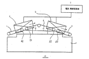
以下、この発明の実施例を図1乃至図4を参照して説明する。図1は、本発明の実施例の構成、機能を図式化した説明用全体図を示す。図2は、右肩上がりの一次ピンホール検査単位1に被検体40がP方向矢視のように進行しているのを水平表示し、電圧印加の電極11,12にて印加している状態と電源部32及び制御回路部31の接続関係を表示した電圧印加方式の一次ピンホール検査単位の説明図である。
【0007】
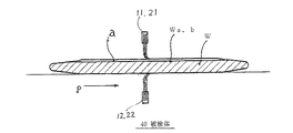
図3は、偏平な形状の含有空気aのある被検体40が水平状態時の流動性の内容物Wの液面Waと空気a状態を示す断面図である。電極11,21を被検体40の表面に接触させても内部の空気の介在のため、含有空気の厚さ次第では、絶縁効果により電圧印加の効果が失われ、閃絡現象が阻害される状態が容易に想起されることが分かる。図4は、被検体40が右肩上がりの一次ピンホール検査単位1と、右肩下がりの二次ピンホール検査単位2の両検査単位のそれぞれにあるときの内容物Wと空気aとの関係を比較するための説明図である。この図示で理解できるように前記検査単位1では、被検体40の後尾部、逆に前記検査単位2では、先頭部にそれぞれ空気が無い状態での検査が可能であることが分かる。
【0008】
次いで、以下、本発明の参考例を図5及び図6を参照して説明する。
図5は、参考例の説明用の側面図で前工程の搬送機50から被検体40を受入れ、スイング姿勢Aのため、その先頭部の空気の無い個所を検査している状態を示す。図6は、図5の状態から、スイング機構73,74を駆動させることにによりスイング架台を角度βだけ降下回動させ左肩上がりの姿勢Bの状態にし、被検体40の空気を浮力により先端に移動させ、空気無しの後部を検査している状態を示す説明図である。なお以上の説明において、ベルトコンベヤの駆動系、機体の支持具などは、一般的且つ常識的な範囲のため図示および説明を省略した。
【0009】
次に、実施例の効用を本発明の機構と動作により説明する。図1のベルトコンベヤ4に搬入載荷された被検体40は右肩上がりに進行し、図2のように一次コンベア4と山形コンベヤの両方に跨った状態に達する。この図示状態に至るまでの陰陽電極11,12により電圧を印加することになるが、被検体40中の含有空気は、図4の一次ピンホール検査単位1のように浮力で先頭部に偏る。
【0010】
そこで、被検体40の先頭部は空気の存在により、その絶縁効果のため適切なピンホールの検査は出来ないで、一次ピンホール検査単位1での検査は、先頭部の空気含有部を除く、より後尾部を有効に実施することとなる。
【0011】
被検体40が進行し、後尾部の検査がおわると、山形ベルトの頂点を過ぎ、右肩下がり部に来れば含有空気は、浮力により上昇し図4に図示のように被検体40の後方に移動するため、先頭部には空気不在となり、ここの二次ピンホール検査単位2で適切な電圧印加による検査が出来るので、ここで被検体40の前後を含めた全体の適正な検査が終了することとなる。
【0012】
図2には、本発明の実施例の制御回路を図示しているが、陰陽両電極11,12により印加された電圧により、被検体40に、若しシール不良やピンホールが存在するときは、両電極間に閃絡電流が発生するので、予め設定された一定値以上の電流により、制御回路31が機能し、シール不良検出の警報の発信、又は不良品の排除信号を次工程の排除機に指示する。
【0013】
次に、本発明の参考例の効用をその機構と動作によって説明する。被検体40が前工程の搬送機50から図5の姿勢Aの状態のベルトコンベヤ60上に進入し、ピンホール検査単位20に到達すると陰陽両電極11,12で先頭部から逐次後方外表面に電圧を印加する。ここでは、被検体40の角度βの傾斜のため含有空気は浮力により後方に偏っているので、先頭部の検査は空気の絶縁阻害の影響なしに適正に行われる。
【0014】
次いで、被検体40の中心部が両電極11,12に達したら、その位置検出のセンサーによる指令にもとずきスイング架台を、駆動装置73及び74により角度βだけ揺動させ、姿勢Bに変更する。この間、含有空気は浮力により被検体40の先頭部に移動し、後方には空気は存在しない。被検体40は引続き進行するため、ここでは後尾部の検査を空気無しの適正検査が出来る。
【0015】
この場合、電圧印加が瞬間的には空気aの上昇移動時に実施され、その間は適正な検査を阻害する虞れがあるが、これは姿勢AからBへの変更速度とコンベヤ速度との兼ね合いであり、移動速度より角度変更の速度が十分速ければ問題は少ない。より確実性を求めるためには、被検体40の中間部が通過した時点で一旦コンベヤ60,70を停止し、空気の移動終了を待ち再度運転し電圧の印加を開始するような運転方式の選択も有効である。
【0016】
なお、実施例のコンベヤ傾斜角度α、参考例のAB間の姿勢設定角度βは、何れも被検体の形状と含有空気量の多寡によって、経済性及び機能上、極力小さな角度になるような選択をすることとなる。
【0017】
【発明の効果】
本発明は以上説明したように、ごく一般的な搬送機構の組み合せや簡単な揺動機構をそれぞれ用いることにより、容易に被検体中の含有空気を浮力により一方から他方へ移動させ、シール不良検査時に何れか一方の端部を絶縁性気体を内包しない状態にできるから、被検体の全面のシール不良を完全かつ確実に検査することができる。
【図面の簡単な説明】
【図1】 本発明の実施例のピンホール検査機を図式化した説明図である。
【図2】 本発明の実施例の電源及び制御回路の接続関係を示す説明図である。
【図3】 同じく、被検体が水平の場合の断面図である。
【図4】 本発明の実施例の被検体と含有空気の所在と電極の相互関係を示した説明図である。
【図5】 本発明の参考例の被検体と含有空気との相対関係を示した説明図である。
【図6】 同じく、スイング動作により、姿勢Aから姿勢Bに変化した状態を示す説明図である。
【符号の説明】
1 一次ピンホール検査単位
2 二次ピンホール検査単位
3 電源、制御回路部
4,6 ベルトコンベヤ
5 山形ベルトコンベヤ
7 機台
10 ピンホール検査機
11,21 陽電極
12,22 陰電極
20 ピンホール検査単位
31 制御回路
32 電源
40 被検体
90 スイング架台[0001]
BACKGROUND OF THE INVENTION
The present invention is food inside is molded of a resin, cosmetic, or pharmaceutical relates sheet Lumpur defect inspection apparatus for inspecting the sealing defects such as pinholes sealed packaging containers filled various forms and the like.
[0002]
[Prior art]
A conventional pinhole inspection apparatus is a single belt conveyor as a means for transporting an object as described in JP-A-62-70725 or Japanese Utility Model Laid-Open No. 9-10008, or a pair of front and rear in series and horizontally. There are many systems in which a voltage is applied to the seal portion of the subject being arranged and being transported.
[0003]
In this method, in the case where the subject contains a large amount of air, depending on the thickness of the air layer on the upper surface when a voltage is applied, a flashing phenomenon in the pinhole due to the insulating effect of the air There was a problem that sufficient performance could not be obtained.
[0004]
[Problems to be solved by the invention]
In the case of Ringer solution flat bottles or liquor paper cup bottles, which are good conductors that are water-based or strong-fluid, the insulation resistance of the sealed gas in the inspection of pinholes in sealed packaging containers filled with air or other gases For this reason, there is a problem that it is extremely difficult to carry out an appropriate inspection to detect a sealing failure such as a pinhole in a packaging material with an applied voltage, and there has been a strong demand for improvement.
[0005]
[Means for solving problems]
The present invention detects and inspects sealing defects and pinholes in the entire seal portion of containers without the influence of gas insulation, such as insulative air, gas-containing aqueous or strong fluid foods, cosmetics, or drugs. Therefore, the buoyancy of the contained gas is utilized by inclining the subject alternately at a certain angle during the examination, so that the voltage application part is always avoided from the gas part.
That is, the present invention first examines the presence or absence of sealing failure of the held while, the portion contacting the sliding contact electrode positioned on the lower side thereon in a state where the subject is a longitudinal direction inclined with respect to the
[0006]
DETAILED DESCRIPTION OF THE INVENTION
【Example】
Hereinafter, describing the actual施例of the present invention with reference to FIGS. Figure 1 shows the actual施例configuration, the entire descriptive was graphically the functional diagram of the present invention. FIG. 2 shows a state in which the
[0007]
FIG. 3 is a cross-sectional view showing the liquid surface Wa of the fluid content W and the air a state when the
[0008]
Next, a reference example of the present invention will be described below with reference to FIGS.
FIG. 5 is a side view for explaining the reference example, and shows a state in which the
[0009]
Next, the utility of the real施例be explained by mechanism and operation of the present invention. The
[0010]
Therefore, due to the presence of air at the top of the
[0011]
When the
[0012]
In FIG. 2, but illustrates a control circuit of the real施例of the present invention, the voltage applied by Yin the
[0013]
Next, the effect of the reference example of the present invention by a mechanism and operation of it. When the
[0014]
Next, when the central portion of the
[0015]
In this case, voltage application is instantaneously performed during the upward movement of the air a, and there is a risk that proper inspection may be disturbed during this time, but this is a balance between the change speed from posture A to B and the conveyor speed. There is little problem if the angle change speed is sufficiently faster than the moving speed. In order to obtain more certainty, selection of an operation method in which the
[0016]
Incidentally, the conveyor inclination angle α of the actual施例, the posture setting angle β between AB of Reference Example, both the amount of the shape and air content of the subject, on the economy and functionality, such that as much as possible a small angle You will make a choice.
[0017]
【The invention's effect】
As described above, the present invention easily moves the contained air in the subject from one side to the other by buoyancy by using a combination of a very general transport mechanism and a simple swinging mechanism, thereby checking the seal failure. Sometimes, one of the end portions can be in a state in which no insulating gas is included, so that a seal failure on the entire surface of the subject can be inspected completely and reliably.
[Brief description of the drawings]
1 is an explanatory diagram graphically the pinhole inspection apparatus of the real施例of the present invention.
It is an explanatory diagram showing the connection relationship between the power supply and control circuit of the real施例of the invention; FIG.
FIG. 3 is also a cross-sectional view when the subject is horizontal.
4 is an explanatory view showing the interrelationship of the location and the electrodes of the subject and containing air real施例of the present invention.
FIG. 5 is an explanatory diagram showing a relative relationship between a subject and air contained in a reference example of the present invention.
FIG. 6 is an explanatory view showing a state in which the posture A is changed from the posture A to the posture B by the swing operation.
[Explanation of symbols]
DESCRIPTION OF
Claims (1)
Priority Applications (1)
| Application Number | Priority Date | Filing Date | Title |
|---|---|---|---|
| JP37668899A JP4435294B2 (en) | 1999-12-17 | 1999-12-17 | Seal defect inspection device |
Applications Claiming Priority (1)
| Application Number | Priority Date | Filing Date | Title |
|---|---|---|---|
| JP37668899A JP4435294B2 (en) | 1999-12-17 | 1999-12-17 | Seal defect inspection device |
Publications (3)
| Publication Number | Publication Date |
|---|---|
| JP2001174442A JP2001174442A (en) | 2001-06-29 |
| JP2001174442A5 JP2001174442A5 (en) | 2007-03-08 |
| JP4435294B2 true JP4435294B2 (en) | 2010-03-17 |
Family
ID=18507562
Family Applications (1)
| Application Number | Title | Priority Date | Filing Date |
|---|---|---|---|
| JP37668899A Expired - Fee Related JP4435294B2 (en) | 1999-12-17 | 1999-12-17 | Seal defect inspection device |
Country Status (1)
| Country | Link |
|---|---|
| JP (1) | JP4435294B2 (en) |
Families Citing this family (3)
| Publication number | Priority date | Publication date | Assignee | Title |
|---|---|---|---|---|
| JP2003194662A (en) * | 2001-12-27 | 2003-07-09 | Nihon Tetra Pak Kk | Sealing state inspection device |
| JP6206643B2 (en) * | 2013-06-04 | 2017-10-04 | ニッカ電測株式会社 | Pinhole inspection apparatus and pinhole inspection method |
| JP2021110598A (en) * | 2020-01-08 | 2021-08-02 | 凸版印刷株式会社 | Paper cup container inspection device inspection method |
-
1999
- 1999-12-17 JP JP37668899A patent/JP4435294B2/en not_active Expired - Fee Related
Also Published As
| Publication number | Publication date |
|---|---|
| JP2001174442A (en) | 2001-06-29 |
Similar Documents
| Publication | Publication Date | Title |
|---|---|---|
| JP2012007931A (en) | Seal check device of bag-packaged product and seal check method | |
| US7167803B2 (en) | Vessel inspection method and vessel inspection device | |
| JP4435294B2 (en) | Seal defect inspection device | |
| JP2780151B2 (en) | Inspection mechanism | |
| JP2001174442A5 (en) | ||
| JP4149187B2 (en) | Pinhole inspection machine | |
| JP2004219345A (en) | Bag opening sealing part inspection device for packing bag | |
| JPH08240569A (en) | Method and device for inspecting pinhole inferiority of food package sheet and food air-tight vessel | |
| JP4416307B2 (en) | Pinhole inspection machine | |
| JPS642208B2 (en) | ||
| JP3575757B2 (en) | Pinhole inspection method and device for plastic ampules | |
| JP3918582B2 (en) | Automatic inspection device for small liquid leaks in containers | |
| JP4825954B2 (en) | Seal defect inspection machine | |
| CN112317346A (en) | Online turn-over conveyor of medicine bag | |
| JP2001272301A (en) | Pinhole inspecting device | |
| JP6206643B2 (en) | Pinhole inspection apparatus and pinhole inspection method | |
| US7111737B2 (en) | Method and a station for checking the integrity of packages, in particular single-dose packages | |
| JP2004279386A (en) | Pinhole inspecting machine | |
| JP2004132713A (en) | Quality inspection method and quality inspection apparatus | |
| JPS642886B2 (en) | ||
| JP2002189021A (en) | Quality inspection apparatus | |
| JP2006337064A (en) | Pinhole inspection device | |
| JP2004132714A (en) | Quality inspection method and quality inspection apparatus | |
| JPH10170467A (en) | Electrode sensor apparatus for inspection of pinhole | |
| IT201800003190U1 (en) | EQUIPMENT FOR THE INSPECTION OF CONTAINERS |
Legal Events
| Date | Code | Title | Description |
|---|---|---|---|
| A521 | Written amendment |
Free format text: JAPANESE INTERMEDIATE CODE: A523 Effective date: 20061213 |
|
| A621 | Written request for application examination |
Free format text: JAPANESE INTERMEDIATE CODE: A621 Effective date: 20061213 |
|
| RD02 | Notification of acceptance of power of attorney |
Free format text: JAPANESE INTERMEDIATE CODE: A7422 Effective date: 20061213 |
|
| A521 | Written amendment |
Free format text: JAPANESE INTERMEDIATE CODE: A821 Effective date: 20061215 |
|
| A977 | Report on retrieval |
Free format text: JAPANESE INTERMEDIATE CODE: A971007 Effective date: 20090731 |
|
| A131 | Notification of reasons for refusal |
Free format text: JAPANESE INTERMEDIATE CODE: A131 Effective date: 20090811 |
|
| A521 | Written amendment |
Free format text: JAPANESE INTERMEDIATE CODE: A523 Effective date: 20091009 |
|
| TRDD | Decision of grant or rejection written | ||
| A01 | Written decision to grant a patent or to grant a registration (utility model) |
Free format text: JAPANESE INTERMEDIATE CODE: A01 Effective date: 20091124 |
|
| A01 | Written decision to grant a patent or to grant a registration (utility model) |
Free format text: JAPANESE INTERMEDIATE CODE: A01 |
|
| A61 | First payment of annual fees (during grant procedure) |
Free format text: JAPANESE INTERMEDIATE CODE: A61 Effective date: 20091223 |
|
| R150 | Certificate of patent or registration of utility model |
Free format text: JAPANESE INTERMEDIATE CODE: R150 |
|
| FPAY | Renewal fee payment (event date is renewal date of database) |
Free format text: PAYMENT UNTIL: 20130108 Year of fee payment: 3 |
|
| FPAY | Renewal fee payment (event date is renewal date of database) |
Free format text: PAYMENT UNTIL: 20140108 Year of fee payment: 4 |
|
| R250 | Receipt of annual fees |
Free format text: JAPANESE INTERMEDIATE CODE: R250 |
|
| R250 | Receipt of annual fees |
Free format text: JAPANESE INTERMEDIATE CODE: R250 |
|
| LAPS | Cancellation because of no payment of annual fees |