JP4434714B2 - Recording apparatus and recording method - Google Patents
Recording apparatus and recording method Download PDFInfo
- Publication number
- JP4434714B2 JP4434714B2 JP2003411058A JP2003411058A JP4434714B2 JP 4434714 B2 JP4434714 B2 JP 4434714B2 JP 2003411058 A JP2003411058 A JP 2003411058A JP 2003411058 A JP2003411058 A JP 2003411058A JP 4434714 B2 JP4434714 B2 JP 4434714B2
- Authority
- JP
- Japan
- Prior art keywords
- recording
- defective
- nozzle
- recording element
- corrected
- Prior art date
- Legal status (The legal status is an assumption and is not a legal conclusion. Google has not performed a legal analysis and makes no representation as to the accuracy of the status listed.)
- Expired - Fee Related
Links
Images


Description
本発明は、複数の記録素子によって構成される記録ヘッドを用いて記録媒体に記録を行う記録装置および記録方法に関し、詳しくは複数の記録素子の中に不良記録素子が発生した場合における、その不良記録素子が本来記録すべきである記録領域を他の正常な記録素子によって補完する記録方法およびその方法を用いた記録装置に関する。 The present invention relates to a recording apparatus and a recording method for recording on a recording medium using a recording head composed of a plurality of recording elements, and more particularly, when a defective recording element occurs in the plurality of recording elements. The present invention relates to a recording method in which a recording area that should be recorded by a recording element is supplemented by another normal recording element, and a recording apparatus using the method.
従来、紙、OHP用シートなどの記録媒体に対して記録を行う記録装置としては、種々の記録方式による記録ヘッドを搭載した形態で提案されている。この記録ヘッドには、ワイヤードット方式、感熱方式、熱転写方式、インクジェット方式によるものなどがあり、特に、インクジェット方式には、記録用紙に直接インクを噴射するものであるので、ランニングコストが安く、静粛性に優れた記録動作が可能な方式として注目されている。 Conventionally, recording apparatuses that perform recording on recording media such as paper and OHP sheets have been proposed in the form of mounting recording heads using various recording methods. This recording head includes a wire dot method, a thermal method, a thermal transfer method, an ink jet method, and the like. In particular, since the ink jet method directly ejects ink onto recording paper, the running cost is low and quiet. It is attracting attention as a method capable of recording operation with excellent characteristics.
また、上記のような記録装置は、記録ヘッドを搭載したキャリッジが水平方向へ移動するキャリッジ走査型となっており、キャリッジ走査型のインクジェットプリンタにおいては、キャリッジ走査によって記録ヘッドに具備された多数のノズルが記録情報に基づき駆動され、1走査記録領域の記録を行った後、記録媒体をキャリッジの進行方向に対して垂直な方向に1走査記録領域分だけ送るようになっており、この走査と記録媒体の搬送とを交互に行うことによって所定の画像が形成される。 The recording apparatus as described above is a carriage scanning type in which a carriage on which a recording head is mounted moves in the horizontal direction. In a carriage scanning type ink jet printer, a large number of recording heads are provided in the recording head by carriage scanning. The nozzle is driven based on the recording information, and after recording one scanning recording area, the recording medium is fed by one scanning recording area in a direction perpendicular to the traveling direction of the carriage. A predetermined image is formed by alternately conveying the recording medium.
記録ヘッド内部にはインク滴を射出するため多数のノズル(吐出口)が構成されている。このノズル内には記録媒体に記録を行うのに使用するインクが充填されている。画像等を記録する場合には、各々のノズルから画像データに対応したものが適時選択され、インクドットを射出し、記録を行っていく。 A large number of nozzles (discharge ports) are formed inside the recording head in order to eject ink droplets. The nozzles are filled with ink used for recording on a recording medium. In the case of recording an image or the like, the one corresponding to the image data is selected from each nozzle as appropriate, and ink dots are ejected to perform recording.
インクジェット記録装置においては、近年、ますます高品位、高解像の記録が望まれており、これを実現する一つの手段として、より微細なノズルを用いて画像の形成を行っている。その一方で、吐出口径が微細なノズルは、従来の吐出口径が大きなノズルに比べて吐出不良となりやすい傾向にある。例えば、塵や増粘インクが吐出口付近に付着することによって、インクの吐出量が変化したり、ひどい場合は不吐出となってしまう。また、微細なノズルを高集積で配列することによって、電気・熱変換体(ヒータ)を用いてインク中に気泡を生成してインクの吐出を行うバブルジェット(登録商標)方式におけるヒータの断線による不吐出、また、インク滴が吐出口面に付着して吐出口を覆うことによって発生する不吐出などが発生する可能性がある。したがって、このようなノズルの吐出不良に起因して記録が不安定となり、結果として記録画像を劣化させてしまう場合もある。 In recent years, in an ink jet recording apparatus, recording of higher quality and higher resolution is desired, and as one means for realizing this, an image is formed using a finer nozzle. On the other hand, a nozzle having a fine discharge port diameter tends to cause a discharge failure compared to a conventional nozzle having a large discharge port diameter. For example, when dust or thickened ink adheres to the vicinity of the ejection port, the ejection amount of the ink changes or, in severe cases, the ejection is not performed. Further, by arranging fine nozzles in a highly integrated manner, bubbles are generated in the ink using an electric / thermal converter (heater), and the ink is ejected to discharge the ink in the bubble jet (registered trademark) system due to disconnection of the heater. There is a possibility that non-ejection or non-ejection that occurs when ink droplets adhere to the ejection port surface and cover the ejection port may occur. Therefore, the recording becomes unstable due to such a discharge failure of the nozzle, and as a result, the recorded image may be deteriorated.
特にシリアル方式のプリンタにおいては、記録ヘッドをスキャンさせて記録をおこなっているので、不吐出ノズルがあると、スキャン方向に沿って記録が行われないラインが発生し、記録画像中に白スジとして現れる。この白スジは記録画像を大きく劣化させる一因となっている。 Especially in serial printers, recording is performed by scanning the recording head, so if there are non-ejecting nozzles, lines that are not recorded along the scanning direction are generated and white streaks appear in the recorded image. appear. This white streak is a cause of greatly degrading the recorded image.
この様な問題は、記録のスループットを高めようとして、ノズル数を数百、数千と増やした場合、それに比例して異常ノズルが発生する確率も増加してしまい、さらに無欠陥の画像を得ることが困難となる。 Such a problem is that when the number of nozzles is increased to several hundreds or thousands in order to increase the recording throughput, the probability of occurrence of abnormal nozzles increases in proportion to that, and a defect-free image is obtained. It becomes difficult.
このような場合の対応方法として、様々な不良記録素子の検出方法や、その結果に応じての回復方法あるいは記録方法などが既に数多く提案されている(例えば、特許文献1〜6参照)。
As a countermeasure method in such a case, various detection methods for various defective recording elements and recovery methods or recording methods depending on the results have already been proposed (see, for example,
特許文献1では、主に1パス記録で、不良チャンネルの画像データを正常チャンネルで記録する方法を開示している。キャリッジが右方向へ記録するときは正常の記録を行い、キャリッジが左方向へ移動する時は、不良記録素子により記録できなかった画素を他の正常な記録素子で記録する代行記録のために1画素の整数倍分だけの紙送りを行ったのち、不良チャネル部分を正常チャンネルで補正する方法を開示している。
また、特許文献3では、補正記録する側の補正ノズルの寿命を考慮し、補正ノズルの使用頻度をカウントし、総使用頻度が所定値に達した場合には補正ノズルを逐次切り替える方法を開示している。本方法も特許文献1に記載の発明と同様に、代行記録を行うと実質2パス記録となる。
また、特許文献2では、ノズル数の約数であるmで割ったn/m個の記録素子を通常の記録走査に用いる第1記録素子とし、別のn(m−1)/m個の記録素子を通常の記録走査には用いない第2記録素子として設定し、第1記録素子が不良である場合のみ第2記録素子を代替記録素子として記録動作させる構成が開示されている。ここでは、基本的に同一画像領域に対し、m回の記録走査と紙送りで画像完成させているマルチパス記録を前提としている。
In
また、特許文献4では、1つのノズルの欠落データを完全に他のノズルで置き換える方法を開示している。記録前に標準のマスクを得た後に、不良ノズルを特定し、その位置によって代替の交換ノズルを選択する。その後、不良ノズルのマスクから記録データを削除し、その記録データを交換ノズルのマスクに追加する方法をとっている。この提案は特許文献2と同様にマルチパス記録を前提としている。
また、特許文献5ではマルチパス印字の場合、1ラスタの記録はNパスならN回の記録走査でN個のノズルを用いて完成させるのだが、N個のノズルの内1または複数ノズルが不吐出ノズルであっても他のN―1個のノズルを使用し、補正する方法が考えられている。他の正常なノズルを用いて補正し、不吐ノズルが記録すべきピクセルが空白ドットにならないようにする方法が考えられている。
Further, in
また、特許文献6では、記録走査方向に不良記録素子と並列する記録素子で補正する方法を開示している。ここでは、ブラックの不良記録素子を、シアン、マゼンタ、イエローの記録素子で補正している。
Further,
上記補正方法を用いることで、不吐出による画像の劣化は改善することができる。
しかし、不吐出ノズルを他の正常なノズルを用いて補正記録を行った場合、補正に用いたノズルの耐久寿命が少なくとも補正に用いられた回数分だけは短縮されてしまう。そして、補正に多く用いられたノズルほど、他の補正に用いられないノズルと比較して早い段階で寿命を迎え、吐出ヨレ、不整吐出、または不吐出を引き起こすこととなる。
By using the above correction method, it is possible to improve image deterioration due to non-ejection.
However, when the non-ejection nozzle is corrected and recorded using another normal nozzle, the durable life of the nozzle used for the correction is shortened at least by the number of times used for the correction. Then, the more frequently used nozzles are used for correction, the life of the nozzles is reached at an earlier stage compared to nozzles that are not used for other corrections, causing ejection deviation, irregular discharge, or non-discharge.
つまり、不吐出による画像の劣化を防止するという観点からは、他の正常なノズルで欠落部分の補正を行う必要があるが、逆に補正に使用する正常ノズルの寿命の観点からは、できるかぎり補正記録を行うべきではないと言える。 In other words, from the viewpoint of preventing deterioration of the image due to non-ejection, it is necessary to correct the missing portion with other normal nozzles, but conversely, from the viewpoint of the life of the normal nozzle used for correction, as much as possible It can be said that correction recording should not be performed.
また、不吐出ノズルによる画像の欠落部分は、発生する位置や量によっても目立ち方が異なる。例えば、形成された画像全体でほんの1箇所だけに1ノズル分の白スジが発生していたとしても、その欠落部分はあまり目立たない。特に、微細なノズルからの小径ドットで画像が形成されている場合は、ほとんど目立たない。一方、比較的狭い領域に2,3本の白スジが集中して発生していると、遠目にはそれらが1本の太い白スジとなって見えて目立ってしまう場合もある。しかしながら、これらの画像欠落部分が従来は一律に補正されていたので、本来ならば補正をしなくても肉眼での画質劣化として認識されないような箇所まで補正しており、無駄に正常なノズルの寿命を縮めることとなっている可能性もある。 In addition, the lack of image due to the non-ejection nozzles differs depending on the position and amount of occurrence. For example, even if a white streak of one nozzle is generated in only one place in the entire formed image, the missing portion is not so noticeable. In particular, when an image is formed with small-diameter dots from a fine nozzle, it is hardly noticeable. On the other hand, if a few white stripes are concentrated in a relatively narrow area, they may appear as one thick white stripe and become conspicuous in the distance. However, since these image missing portions have been corrected uniformly in the past, corrections have been made to areas that would not be recognized as image quality degradation with the naked eye even if correction is not performed. There is also a possibility that the lifetime will be shortened.
この問題はインクジェット記録装置に限らず、複数の記録素子を用いて記録を行う他の記録装置に対しても言えることである。各記録素子が記録する1記録領域が微細になればなるほど、その不良記録素子の記録の欠落箇所は、単独であれば、画像全体としては目立ちにくくなる一方で、複数の記録欠落が集中して発生している領域に関しては、その記録の欠落が目立ち、それが画像全体の画質に大きく影響するものとなる。 This problem can be applied not only to the ink jet recording apparatus but also to other recording apparatuses that perform recording using a plurality of recording elements. As one recording area recorded by each recording element becomes finer, if the defective recording element of the defective recording element is single, it becomes less conspicuous as an entire image, but a plurality of recording defects are concentrated. As for the generated area, the lack of recording is conspicuous, which greatly affects the image quality of the entire image.
本発明は以上の問題を鑑みて考案したもので、不吐出ノズルなど不良記録素子が複数存在する場合、その不良記録素子が本来記録すべき画素全てを補正対象とするのではなく、他の正常な記録素子の寿命との相互関係で効率よく補正できるように、記録ヘッドにおける不良記録素子の位置関係や記録媒体やインクなどの各種条件に基づいて、補正対象とする不良記録素子を選択する選択方法および、選択された不良記録素子の記録データを補完する補正方法を備えた記録方法および該方法を用いた記録装置を提供する。 The present invention has been devised in view of the above problems. When there are a plurality of defective recording elements such as non-ejection nozzles, the defective recording elements do not target all the pixels that should be recorded, but other normal elements. To select a defective recording element to be corrected based on the positional relationship of the defective recording element in the recording head and various conditions such as the recording medium and ink so that the correction can be made efficiently in correlation with the life of the various recording elements. There are provided a method, a recording method including a correction method for complementing recording data of a selected defective recording element, and a recording apparatus using the method.
上記課題を解決するための本発明による記録装置は、複数の記録素子を有する記録ヘッドを用いて記録媒体に対して記録を行う記録装置であって、前記複数の記録素子の中に不良記録素子が複数存在する場合に、不良記録素子間の距離を算出する算出手段と、前記算出手段によって算出された不良記録素子間の距離が予め定められた設定値以下であるどうかを判断する判断手段と、前記判断手段によって設定値以下と判断された不良記録素子の組み合わせから補正対象の不良記録素子を選択する選択手段と、前記選択手段によって選択された不良記録素子に対応する記録データが正常な記録素子によって記録されるように、前記正常な記録素子に対応する記録データを補正する補正手段と、前記補正手段によって補正された記録データに基づいて前記記録ヘッドを駆動する駆動手段と、を具えることを特徴とする。 In order to solve the above problems, a recording apparatus according to the present invention is a recording apparatus that performs recording on a recording medium using a recording head having a plurality of recording elements, and includes a defective recording element among the plurality of recording elements. Calculating means for calculating the distance between the defective recording elements, and determining means for determining whether the distance between the defective recording elements calculated by the calculating means is equal to or less than a predetermined set value. selecting means for selecting a defective recording element to be corrected from the combination of the a defective recording element determined to be equal to or less than Therefore set value to said determining means, the recording data corresponding to the thus selected defective recording element to said selection means normally as recorded by Do recording element, and correcting means for correcting the recording data corresponding to the normal recording element, based on the recording data corrected by said correction means Characterized in that it comprises a driving means for driving said recording head Te.
また、前記設定値は、記録媒体の種類、記録に用いるインク、インクの吐出量、記録媒体の同一領域を記録ヘッドが走査する回数、およびそれらの組み合わせに応じて、適宜設定されるものであってもよい。 The set value is appropriately set according to the type of the recording medium, the ink used for recording, the ink discharge amount, the number of times the recording head scans the same area of the recording medium, and the combination thereof. May be.
また、記録素子は配列順に番号が割り当てられ、前記選択手段は、前記設定値以下と判断された不良記録素子の組み合わせのうち、番号が小さい方、または大きい方といったようにいずれか一方を補正対象として選択するものであってもよい。 Further, the recording elements are assigned numbers in the order of arrangement, and the selection means corrects one of the combinations of defective recording elements determined to be equal to or less than the set value, such as the smaller number or the larger number. May be selected.
また、選択は、前記設定値以下と判定された不良記録素子の組すべてに対して、各組を構成する2つの不良記録素子のいずれか一方を補正対象として選択するものであってもよい。 In addition, the selection may be performed by selecting one of two defective recording elements constituting each set as a correction target for all the combinations of defective recording elements determined to be equal to or less than the set value.
また、本発明の記録方法は、複数の記録素子を有する記録ヘッドを用いて記録媒体に対して画像を記録する記録方法であって、前記複数の記録素子の中に不良記録素子が複数存在する場合に、不良記録素子間の距離を算出する算出工程と、前記算出工程にて算出された不良記録素子間の距離が予め定められた設定値以下であるどうかを判断する判断工程と、前記判断工程にて設定値以下と判断された不良記録素子の組み合わせから補正対象の不良記録素子を選択する選択工程と、前記選択工程にて選択された不良記録素子に対応する記録データが正常な記録素子によって記録されるように、前記正常な記録素子に対応する記録データを補正する補正工程と、前記補正工程にて補正された記録データに基づいて画像を記録する記録工程と、を具えることを特徴とする。 The recording method of the present invention is a recording method for recording an image on a recording medium using a recording head having a plurality of recording elements, and a plurality of defective recording elements exist in the plurality of recording elements. A calculation step for calculating a distance between the defective recording elements, a determination step for determining whether the distance between the defective recording elements calculated in the calculation step is equal to or less than a predetermined set value , and the determination A selection step of selecting a defective recording element to be corrected from a combination of defective recording elements determined to be equal to or less than a set value in the step, and a recording element in which recording data corresponding to the defective recording element selected in the selection step is normal as documented by, ingredients and a correction step of correcting the record data corresponding to the normal recording element, and a recording step of recording an image based on the recording data corrected by said correction step And wherein the Rukoto.
本発明は、インクジェット記録装置に適用可能であり、該インクジェット記録装置においては、不良記録素子は、インク不吐出のノズルである。 The present invention is applicable to an ink jet recording apparatus. In the ink jet recording apparatus, the defective recording element is a nozzle that does not eject ink.
以上の構成によれば、不良記録素子が複数存在する場合、その複数の不良記録素子が本来記録すべき画素の全てを補正対象とするのではなく、記録ヘッドにおける不良記録素子の位置関係や記録媒体、インクなどの各種条件に基づいて、補正対象とする不良記録阻止を選択し、選択された不良記録素子が本来記録すべき画素に対してのみ、他の正常な記録素子で記録するような補正を行うことで、無駄に正常な記録素子の寿命を縮めることなく、記録ヘッドの耐久性を極力損なわずに高画質の記録を行うことが可能となる。 According to the above configuration, when there are a plurality of defective recording elements, not all of the pixels that should be recorded by the plurality of defective recording elements are subject to correction, but the positional relationship and recording of the defective recording elements in the recording head. Based on various conditions such as medium, ink, etc., defective recording prevention to be corrected is selected, and recording is performed with other normal recording elements only for the pixels that the selected defective recording elements are supposed to record. By performing the correction, it is possible to perform high-quality recording without unnecessarily reducing the durability of the recording head without shortening the life of a normal recording element.
本発明の実施形態は、記録装置において、不良記録素子による記録の欠落部分を他の正常な記録素子で補完する上で、全ての不良記録素子に対して補完をするのではなく、記録の欠落が目立つ箇所に該当する不良記録素子を選択し、その選択された不良記録素子分に対して正常な記録素子による補正処理を施す。したがって、全ての不良記録素子分の記録データを補完するわけではなく、記録の欠落が目立つ箇所に対してのみ記録データを補完するので、この補正処理に使用される正常記録素子の数を抑えることになる。 According to an embodiment of the present invention, in a recording apparatus, when a defective portion of recording due to a defective recording element is complemented by another normal recording element, not all defective recording elements are complemented, but recording loss The defective recording element corresponding to the position where the image is conspicuous is selected, and correction processing by the normal recording element is performed on the selected defective recording element. Therefore, the recording data for all the defective recording elements is not supplemented, and the recording data is supplemented only for the portion where the lack of recording is conspicuous, so that the number of normal recording elements used for this correction processing is suppressed. become.
本発明の最良の実施形態として、インクジェット記録装置をあげ、以下に説明するが、本発明はこれに限らず、複数の記録素子を用いて記録を行う記録装置に適用可能なものである。 The best embodiment of the present invention is an ink jet recording apparatus, which will be described below. However, the present invention is not limited to this, and can be applied to a recording apparatus that performs recording using a plurality of recording elements.
本発明の最良の実施形態について、以下に図面を参照して説明する。
(装置概要)
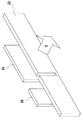
図1は、本発明の実施形態であるインクジェット記録装置の記録部分を示す模式図である。
1は紙またはプラスチックシート等からなる記録シートであって、不図示のカセット等に複数枚積層された状態で収納されており,その積層されたシート束の最上位または最下位記録シート1の一面に接する給紙ローラ(不図示)が回転することによってカセットから記録シートが一枚ずつ供給され、一定間隔を隔ててプラテンに配置される。そして、プラテンに配置された記録シート1は、それぞれ個々のステッピングモータ(不図示)によって駆動する一対の第1搬送ローラ3及び一対の第2搬送ローラ4によって矢印A方向(以下「副走査方向」ともいう)に搬送される。
The best mode for carrying out the present invention will be described below with reference to the drawings.
(Device overview)
FIG. 1 is a schematic diagram showing a recording portion of an ink jet recording apparatus according to an embodiment of the present invention.
1 is a recording sheet made of paper or plastic sheet, and is stored in a stacked state in a cassette (not shown). One surface of the uppermost or
6は前記副走査方向Aと直交する主走査方向に保持された水平なガイドシャフト9に沿って直線往復動可能に設けられたキャリッジである。このキャリッジ6はべルト7及びプーリ8a,8bを介してキャリッジモータ23に連動しており、前記キャリッジモータ23を駆動することにより、前記ガイドシャフト9に沿って往復動を行なう。キャリッジ6には記録ヘッド5が搭載されている。記録ヘッド5は、複数のノズルからなるノズル面が記録媒体1と対峙するように設置されている。
A
上記構成を有する記録部において、記録ヘッド5は、キャリッジの移動に伴って矢印B方向(以下、「主走査方向」ともいう)に移動しながら記録信号に応じてインクを記録シート1に吐出し、副走査方向において記録ヘッドのノズル数の配設幅に対応する1走査記録領域に記録を行う。そして、必要に応じて記録ヘッド5はホームポジションに戻り、回復装置によってノズルの目詰まりを解消する。また、記録ヘッド5が記録媒体上を一走査すると、一対の搬送ローラ3,4の駆動によって記録シート1を矢印A方向へ前記1走査記録領域分搬送する。このように、記録ヘッド5の記録走査と搬送ローラ3,4による所定量の記録媒体の搬送とが交互に繰り返されることによって、記録媒体全体に画像が形成される。
In the recording unit having the above configuration, the
また、主走査方向において、記録シート1を挟んで両側には、予備吐出を行うための不図示の予備吐口が設置され、各走査スキャンにおいて、往復どちらの方向から記録を行う場合でも予備吐出をおこなうことができる。
In addition, preliminary discharge ports (not shown) for performing preliminary discharge are installed on both sides of the
図2は、インクジェット記録装置のインク供給系を示す模式図である。
インクは、メインのインクタンク201からチューブ207とジョイント208を経由して、キャリッジ6上のサブのインクタンク202に補給されてから、記録ヘッド9に供給される。メインのインクタンク201において、201Y,201M,201C,201Bは、それぞれイエロー、マゼンタ、シアン、およびブラックのインクの収容部である。記録ヘッド9は、キャリッジ2と共に、シャフト10に沿って主走査方向に移動する。203はバッファ室である。208はピン残検回路である。
FIG. 2 is a schematic diagram showing an ink supply system of the ink jet recording apparatus.
Ink is supplied from the
回復装置は、キャップ部分に記録に関与しないインク吐出を行う予備吐出や、ノズル面をキャッピングして吸引ポンプなどによって吸引する吸引処理などを行う。また、記録走査時にノズルワイパー上に記録ヘッドを走査させることによってノズル面をぬぐうワイピングなどもある。 The recovery device performs preliminary ejection for ejecting ink that does not participate in recording to the cap portion, suction processing for capping the nozzle surface and suctioning with a suction pump or the like. There is also wiping that wipes the nozzle surface by scanning the recording head on the nozzle wiper during recording scanning.
図3はインクジェット記録装置のワイパーの外観を示す模式図である。
図4は記録ヘッドの外観を示す模式図である。
図5は、図4のV−V線での断面図である。
黒のノズルワイパー20(図3参照)の幅は、図4の黒の記録ヘッドの、ノズル面15が形成されたプレート(以下「チップ」ともいう)の幅Fよりも狭く作成されている。そして、図5に示すように黒およびカラーのノズル面15は、記録ヘッドのTAB面30よりも若干内側へ引っ込んでいる。このノズル面のくぼみ部分にワイパーそれぞれが入りこんで払拭する。なお、ノズル面がTAB面30よりも内側に引っ込んでいるのは、記録媒体との接触を回避するためである。同様にカラー用のノズルワイパー21は、カラー用のプレートが3色分並んだ幅以下の幅とした。さらに、黒用のノズルワイパー20とカラー用のノズルワイパー21と平行に設けられ、両者の合計よりも長いワイパー22はTAB面30を払拭するためのものである。
FIG. 3 is a schematic diagram showing the appearance of the wiper of the ink jet recording apparatus.
FIG. 4 is a schematic diagram showing the appearance of the recording head.
5 is a cross-sectional view taken along line VV in FIG.
The width of the black nozzle wiper 20 (see FIG. 3) is made narrower than the width F of the plate (hereinafter also referred to as “chip”) on which the
図3のワイパーは、不図示のワイパーホルダーに、同じく不図示のワイパー固定金具を用いて取り付けられており、ワイパーの位置あわせはワイパー20,21,22に開けられた孔、およびワイパーホルダーに設けられたピンとの勘合によって行われる。ワイパー20,21,22は、図3および図4中に示した矢印C方向に向け、パージモーター113によって駆動され、ノズル面(オリフィス)およびTAB面を払拭する。ワイピング動作が終了するとキャリッジをワイピング領域の外に退避し、ワイパーを逆方向に駆動しワイピングを開始するポジションに戻す。
The wiper shown in FIG. 3 is attached to a wiper holder (not shown) using a wiper fixing bracket (not shown). The wiper is positioned in the holes formed in the
図4に見られるように、黒ヘッドでは1cmあたり約245ノズルの密度で640ノズルが配列されており、カラーヘッドでは各色とも1cmあたり約490ノズルの密度で1280ノズルが配列されている。 As shown in FIG. 4, the black head has 640 nozzles arranged at a density of about 245 nozzles per cm, and the color head has 1280 nozzles arranged at a density of about 490 nozzles per cm for each color.
図5に示すように、メインタンクから供給されたインクはインク供給口23から矢印Dの方向に進行し、各記録ヘッド内のフィルター25よりも手前に設けられたインク液室24に導かれる。その後、図中の矢印Eの方向に進み、フィルター25によって混入したゴミ等がろ過された上で、フィルターよりもノズル面よりに設けられたインク液室26に導かれ、オリフィスプレート下面に形成されたインクを吐出する各ノズルへと導かれる。
As shown in FIG. 5, the ink supplied from the main tank travels in the direction of arrow D from the
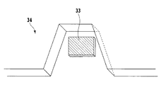
図6および図7は、図4に示した記録ヘッドのノズル部分の拡大図を示した。
図5に示すインク液室26は、インクを通す開口部32を有するオリフィスプレート31(図7参照)と、液室形成部材34とヒーター33を搭載したヒーターボードにより形成されている。この部分に貯留されたインクはヒーター33の加熱により気泡を生成し気泡の膨張に伴ってオリフィスプレートから押し出され、空気との界面張力によって球状の液滴となり記録媒体に向かって飛翔する。
6 and 7 show enlarged views of the nozzle portion of the recording head shown in FIG.
The
次にこのような機構のインクジェット記録装置の電気的構成について説明する。
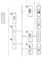
図8はインクジェット記録装置の電気的構成を示すブロック図である。
302はCPUであり、マイクロプロセッサ等で構成されている。304はメモリであり、CPU302によって実行される制御プログラムや各種データを格納しているROM、及びCPU302のワークエリアとして使用されると共に記録画像データなどの各種データの一時記憶等を行うRAM等によって構成されている。305は入出力部であり、ホストコンピュータ301からの記録データを入力し、またホストコンピュータ側へインクジェット記録装置の状態を出力する。
Next, the electrical configuration of the ink jet recording apparatus having such a mechanism will be described.
FIG. 8 is a block diagram showing an electrical configuration of the ink jet recording apparatus.
306は記録ヘッド駆動用ドライバであり、CPU302からの駆動指令に従い、記録ヘッドの駆動を制御する。307はモータ駆動用ドライバであり、キャリッジモータ、給紙モータ、搬送ローラ駆動モータなど、各種駆動部のモータの駆動をCPU302からの駆動指令に従い制御する。このほかに吸引ポンプなどの回復機構を駆動させる回復機構用ドライバ308などが設けられていてもよい。
CPU302は入出力部305を介してホストコンピュータ301からの各種情報(例えば文字ピッチ、文字種類等)に従って、メモリに格納された制御プログラムを起動し、各駆動部を駆動させる。
The
このようなインクジェット記録装置において、不吐出ノズルの検出は、テストパターンを定期的に記録することなどによって検知される。テストパターンの形式は特に限定しないが、例えば、1ノズルごとに所定長さの線を記録し、全体として階段状の線となるテストパターンなどが不吐出ノズルの検知用として従来より用いられている。検知された不吐出ノズルはROM等に格納され、記録データをノズルごとの吐出データに展開する際に参照される。 In such an ink jet recording apparatus, detection of a non-ejection nozzle is detected by regularly recording a test pattern. The format of the test pattern is not particularly limited. For example, a test pattern in which a line having a predetermined length is recorded for each nozzle and a stepped line as a whole is used for detecting a non-ejection nozzle. . The detected non-ejection nozzle is stored in a ROM or the like, and is referred to when developing the recording data into ejection data for each nozzle.
(補正記録方法)
次に、不吐出ノズル分の記録データを補完する補正記録方法について説明する。この補正記録方法は、以下の実施例に示す方法で選択された補正対象の不吐出ノズルが本来記録するはずの画素に対して他の正常なノズルで行う方法である。
補正記録は1パス記録の場合とマルチパス記録の場合で、補正方法が異なる。
(Correction recording method)
Next, a correction recording method for complementing the recording data for the non-ejection nozzles will be described. This correction recording method is a method that is performed with other normal nozzles for pixels that should be recorded by the non-ejection nozzles to be corrected selected by the method shown in the following embodiments.
In the correction recording, the correction method differs between the case of 1-pass recording and the case of multi-pass recording.
まず、マルチパス記録時の補正記録方法について説明する。
図9はマルチパスの記録方法を説明するための模式図である。
この図では4パス記録の場合を例としている。説明を簡単にするために、記録ヘッド5は16ノズルで構成されるものとした。
First, a correction recording method at the time of multipass recording will be described.
FIG. 9 is a schematic diagram for explaining a multi-pass printing method.
In this figure, the case of 4-pass recording is taken as an example. In order to simplify the explanation, the
4パス記録の場合、記録ヘッド5のノズルを4ノズルごとの4ブロックに分割する。そして、記録時は、主走査方向に記録走査を行った後の、紙送り量は副走査方向に4ノズル分とする。1ブロックでの記録領域101は縦4×横24(画素)の領域となる。
In the case of 4-pass printing, the nozzles of the
ブロックを下から順に、A、B、C、Dとすると、記録領域101に記録を行う場合には、Aから順にB,C,Dのブロックで、4回の記録走査をおこなうことで画像を完成させる。
If the blocks are A, B, C, and D in order from the bottom, when recording in the
ここで、記録領域101の中の斜線で表示した領域(1ラスタ分)に注目すると、この1ラスタの領域の画像を完成するには、まず1回目の記録走査で記録ヘッドが主走査方向に走査し、AブロックのN16ノズルが所定の画素に記録を行う。次に、主走査方向と直交する副走査方向に4ノズル分紙送りを行い、記録走査し、BブロックのノズルN12で記録をおこなう。次に、紙送り後にCブロックのノズルN8を用いて同様に記録し、最後にDブロックのノズルN4で記録し、所定の画素への記録を完了させる。つまり4パス印字の場合、1ラスタの記録領域はN4,N8,N12,N16の4ノズルを用いて記録をおこなうことになる。
Here, when attention is paid to the hatched area (one raster) in the
記録領域101の斜線で表示したラスタを横方向をL1からL24というように指数を割り振り、画素を指定する。その斜線表示部分を取り出したものが図10である。
図10(a)は全ノズルが正常な場合の各走査の記録結果である。
同図に示すように、第1記録走査でノズルN16がLN+1(N=0,1,2,…)の画素を記録し、第2記録走査でノズルN12がノズルLN+2の画素を、第3記録走査でノズルN8がLN+3を、第4記録走査でノズルN4がLN+4を記録するような記録方法を行うと、L1からL24全ての画素にドットを記録する場合、4回の記録走査で記録が完成される。
An index is assigned to the raster displayed in diagonal lines of the
FIG. 10 (a) shows the recording result of each scan when all the nozzles are normal.
As shown in the figure, the nozzle N16 records the pixel of LN + 1 (N = 0, 1, 2,...) In the first recording scan, and the nozzle N12 records the pixel of the nozzle LN + 2 in the second recording scan. When a recording method is performed in which the nozzle N8 records LN + 3 in the third recording scan and the nozzle N4 records LN + 4 in the fourth recording scan, 4 dots are recorded in all pixels from L1 to L24. Recording is completed by one recording scan.
図10(b)は、N16が不吐出ノズルであった場合の各走査の記録結果である。
ここで、ノズルN16が不吐出ノズルであるので、LN+1の画素が記録されず空白となる。したがって、4パス終了後の記録結果は、LN+1の画素だけが点々と欠落したものとなる。しかし、1本のライン上で点々と欠落しているので、肉眼で見ると、ドットの大きさやパス数などによっては1本の線で欠落しているように見える。つまり、白スジとなる。
FIG. 10B shows a printing result of each scan when N16 is a non-ejection nozzle.
Here, since the nozzle N16 is a non-ejection nozzle, the LN + 1 pixels are not recorded and are blank. Therefore, the recording result after the end of the 4th pass is the one in which only LN + 1 pixels are missing. However, since the dots are missing on one line, it appears to be missing on one line depending on the size of the dot and the number of passes. That is, it becomes a white stripe.
この白スジを防止するために、他の正常なノズルを使用して補正する原理について説明する。図10(C)に示すように、本来ノズルN16がおこなう予定であった記録を第2記録走査でノズルN12が、LN+1とLN+2の画素二つに連続してドットを打ち込むことによって、ドットの欠落をなくす。以下、第3、第4記録走査は正常な場合と同様に行う。このように補正をおこなうことで、データに対して1対1の完全な記録をおこなうことが可能となる。なお、この場合はノズルN12を用いて補正を行ったが、ノズルN4,N8を用いて補正を行っても良い。更に、ノズルN4,N8,N12にデータを分割して3ノズルを用いて補正をおこなうのも良い。 In order to prevent this white stripe, the principle of correction using another normal nozzle will be described. As shown in FIG. 10C, the nozzle N16 originally performs printing in the second recording scan, and the nozzle N12 strikes dots continuously in two pixels of LN + 1 and LN + 2, thereby missing dots. Is lost. Hereinafter, the third and fourth recording scans are performed in the same manner as in the normal case. By performing correction in this way, it becomes possible to perform complete one-to-one recording on data. In this case, the correction is performed using the nozzle N12, but the correction may be performed using the nozzles N4 and N8. Further, the data may be divided into nozzles N4, N8, and N12 and correction may be performed using three nozzles.
本例は4パス記録の場合を例としたが、他のマルチパス記録の場合も、同様に同じラスタの記録を担当する複数の正常なノズルに不吐出ノズルのデータを割り振り、補正を行うようにすればよい。 In this example, four-pass printing is used as an example, but in other multi-pass printing as well, non-ejection nozzle data is assigned to multiple normal nozzles that are responsible for printing the same raster, and correction is performed. You can do it.
次に1パス記録時の補正記録方法について説明する。
1パス記録では、1ラスタの記録を担当するノズルは1ノズルのみとなり、マルチパス記録のように同じラスタを記録する他のノズルにデータを割り振り、補正記録を行わせることはできない。そこで、1パス記録の補正は、不吐出ノズルのデータを隣接する上下のノズルに割り振り、隣接ノズルに補正記録を行わせる。
Next, a correction recording method at the time of 1-pass recording will be described.
In 1-pass recording, only one nozzle is responsible for recording one raster, and correction recording cannot be performed by assigning data to other nozzles that record the same raster as in multi-pass recording. Therefore, in the correction of the one-pass printing, the data of the non-ejection nozzle is allocated to the upper and lower nozzles adjacent to each other and the correction printing is performed by the adjacent nozzle.
図11(a)に示すように、正常なノズルN14、N16にはさまれたノズルN15が不吐出ノズルである。
記録領域にノズルN14、N15、N16のノズルが記録するデータがある場合、不吐出ノズルであるノズルN15のデータを図11(b)のようにカラム毎に上下の隣接ノズルに割り振る。ただし、既に割り振り先にデータが存在する場合には割り振らない。また、ノズルN15に対応するラスタデータは、不良ノズルであるためマスクし、補正後はヌルデータとする。 この場合、隣接上下2ノズルにデータを割り振ったが、上下のどちらか一方に割り振るのでもよい。
As shown in FIG. 11A, a nozzle N15 sandwiched between normal nozzles N14 and N16 is a non-ejection nozzle.
When there is data to be recorded by the nozzles N14, N15, and N16 in the recording area, the data of the nozzle N15 that is a non-ejection nozzle is allocated to the upper and lower adjacent nozzles for each column as shown in FIG. However, if data already exists in the allocation destination, it is not allocated. The raster data corresponding to the nozzle N15 is masked because it is a defective nozzle, and is corrected to null data. In this case, the data is allocated to the adjacent upper and lower two nozzles, but may be allocated to either the upper or lower side.
このように、不吐出ノズルのデータを隣接ノズルに割り振り、記録を行わせることで補正を行う。この場合、不吐出ノズルが記録すべき画素に対しては記録は行われず、それに隣接するラスタに代替で記録が行われるため、完全に画像の欠落部分が補正されるわけではない。しかしながら、不吐出ノズルによって1ラスタ分のデータが完全に消えてしまう場合と比較すると、周囲のラスタに記録を行うことで、白スジは大幅に緩和され、画質を向上させることができる。 In this way, correction is performed by allocating non-ejection nozzle data to adjacent nozzles and performing recording. In this case, recording is not performed on the pixels to be recorded by the non-ejection nozzle, and recording is performed on the raster adjacent to the non-ejection nozzle, so that the missing portion of the image is not completely corrected. However, as compared with the case where the data for one raster is completely erased by the non-ejection nozzles, white streaks are greatly reduced by recording on the surrounding raster, and the image quality can be improved.
本発明では、全ての不吐出ノズルに対応してこのような補正処理を実行するのではなく、選択された一部の不吐出ノズルに対してのみ補正処理を実行する。したがって、以下に補正処理を実行する不吐出ノズルの選択方法について説明する。 In the present invention, such correction processing is not executed for all the non-ejection nozzles, but correction processing is executed only for some selected non-ejection nozzles. Therefore, a non-ejection nozzle selection method for executing the correction process will be described below.
(第1実施例)
本実施例では、記録ヘッドにおける不吐出ノズルの位置関係によって、補正対象とする不吐ノズルを選択する選択方法を説明する。
(First embodiment)
In this embodiment, a selection method for selecting a discharge failure nozzle to be corrected according to the positional relationship of the discharge failure nozzles in the recording head will be described.
最初に記録ヘッド5における不吐出ノズルの位置と白スジの見え方について説明する。 図12は不吐出によって画像に現れる白スジを説明するための模式図である。
記録ヘッドに不吐出ノズルが存在する場合、不吐出ノズルが記録すべきラスタに対して記録が行われないため、図12に示すように主走査方向に向かって画像に白スジが発生する。
First, the position of the non-ejection nozzles in the
When non-ejection nozzles are present in the recording head, recording is not performed on the raster to be recorded by the non-ejection nozzles, so white streaks occur in the image in the main scanning direction as shown in FIG.
図12に示したのは、1パス記録で不吐出ノズルが1ノズルのみの場合についてであるが、不吐出ノズルが複数ノズル存在する場合、記録ヘッドにおける不吐出ノズル同士の位置関係によって画像に表れる白スジの見え方は変化する。 FIG. 12 shows the case where there is only one non-ejection nozzle in one-pass printing, but when there are a plurality of non-ejection nozzles, they appear in the image due to the positional relationship between the non-ejection nozzles in the recording head. The appearance of white stripes changes.
不吐出ノズルが2ノズルある記録ヘッドの場合を例にとって説明する。
図13(a)は、不吐出ノズル両者の間隔が広い場合であり、同図(b)は、不吐出ノズル両者の間隔が近い場合である。
An example of a recording head having two non-ejection nozzles will be described.
FIG. 13A shows a case where the interval between the non-ejection nozzles is wide, and FIG. 13B shows a case where the interval between the non-ejection nozzles is close.
不吐出ノズル両者の間隔が近い場合は、広い場合と比較して、2本の白スジが互いに近づいているので、人の目には1本の白スジとして強調されて見える。つまり2本の白スジが接近した場合の方がより明確な白スジとして認識でき、この白スジは画像上目立つものになる。 When the distance between the non-ejection nozzles is close, the two white stripes are close to each other compared to the wide case, so that it appears to be emphasized as one white stripe in the human eye. That is, when two white stripes approach each other, it can be recognized as a clearer white stripe, and this white stripe becomes conspicuous on the image.
このような白スジ同士の強調作用によって、例えば1本の白スジが単独で存在するだけでは、視覚的に白スジとして認識できず、画質として問題ない場合でも、2本の白スジが近接して存在する場合には明確な白スジとして認識できるようになり、画質を大きく劣化させるといったことが起こってくる。 Due to the enhancement of white stripes, for example, if there is only one white stripe, it cannot be visually recognized as a white stripe, and even if there is no problem in image quality, the two white stripes are close together. If it exists, it can be recognized as a clear white streak and the image quality is greatly degraded.
以上のような記録ヘッドの位置関係に起因する視覚的な白スジの変化に対応するために、本実施例では、不吐出ノズルの位置情報から補正対象とする不吐出ノズルを選択する。そして、選択した補正対象不吐ノズルに対して補正記録を行うようにする。 In the present embodiment, the non-ejection nozzle to be corrected is selected from the positional information of the non-ejection nozzle in order to cope with the change in the visual white stripe caused by the positional relationship of the recording head as described above. Then, correction recording is performed on the selected correction target discharge failure nozzle.
補正対象とする不吐出ノズルの選択方法について説明する。
不吐出ノズルが複数存在する場合、画質に影響を与える不吐出ノズルに対してのみ補正を行うために、記録ヘッド内における不吐出ノズルの位置情報をもとに次の方法で補正対象とする不吐出ノズルの選択を行う。なお、不吐出ノズルは上述したように、あらかじめ不吐出ノズル検知パターンの記録などによって検知されており、ROM等に格納された不吐出ノズルのリストを呼び出して、以下の選択方法によって画質に影響を与えると判断されたもののみを選択されるものとする。
本実施例の記録ヘッド5内は、シアン、マゼンタ、イエローはそれぞれ1280ノズル、黒は640ノズルが構成されている。
A method for selecting a non-ejection nozzle to be corrected will be described.
When there are multiple non-ejection nozzles, in order to perform correction only for non-ejection nozzles that affect image quality, the following method should be used to correct the non-ejection nozzles in the print head. Select the discharge nozzle. As described above, the non-ejection nozzles are detected in advance by recording the non-ejection nozzle detection pattern, etc., and a list of non-ejection nozzles stored in a ROM or the like is called to affect the image quality by the following selection method. Only those that are judged to be given shall be selected.
In the
図14に示されるように、カラーはN0番からN1279番まで、各ノズルに対して番号が割り当てられている。黒はN0番からN639番まで、番号が割り当てられている。黒のノズル配列はカラーと同じであるため、ここでは図示を省略する。 As shown in FIG. 14, colors are assigned to the nozzles from N0 to N1279. Black is assigned a number from N0 to N639. Since the black nozzle array is the same as the color, the illustration is omitted here.
ここで、2つの不吐出ノズルが存在する場合、ある程度の距離不吐出ノズル同士が離れていれば画像に白スジが認識できない、あるいは気にならない程度であるノズル間隔(距離)をノズル間隔設定値と定義し、以下の説明をおこなう。 Here, when there are two non-ejection nozzles, the nozzle interval setting value is the nozzle interval (distance) that the white streak cannot be recognized or noticed if the distance non-ejection nozzles are separated to some extent. And the following explanation.
ノズル間隔設定値が30ノズル(約635μm)である場合を例にとって説明する。
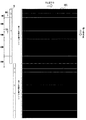
図15はノズル番号N100、N120、N200、N500、N510、N700、N1100のノズルが不吐出の記録ヘッドで記録ヘッド幅分の記録領域101に対する記録を1回の記録走査において行う1パス記録を行った場合を模式的に示す図である。
A case where the nozzle interval setting value is 30 nozzles (about 635 μm) will be described as an example.
FIG. 15 shows a one-pass printing in which the nozzles N100, N120, N200, N500, N510, N700, and N1100 perform recording on the
図からわかるように、画像上で示す位置に、白スジが発生する。図15は、記録領域101の全ての画素に対して記録を行った場合について示している。この場合、画質に影響を与えるのは、不吐出ノズル同士がノズル間隔で30ノズル以内に接近している場合であり、30ノズル以上離れている場合は画像に白スジは現れない。つまり、ノズル間隔が30ノズル以内の不吐出ノズルに対して補正記録を行えば、画質的に問題ない記録物が得られるのである。
As can be seen from the figure, white streaks occur at the positions shown on the image. FIG. 15 shows a case where recording is performed on all the pixels in the
そこで、ノズル番号から不吐出ノズル間の距離を算出し、各不吐出ノズル間の距離から補正対象の不吐出ノズルを選出する。各不吐ノズル同士のノズル間隔はN100とN120では、20ノズル間隔(約423μm)というように簡単に計算できる。このように複数不吐出ノズルが記録ヘッドに存在する場合には、各不吐出ノズル間の距離を全て算出する。 Therefore, the distance between the non-ejection nozzles is calculated from the nozzle number, and the non-ejection nozzle to be corrected is selected from the distance between the non-ejection nozzles. The nozzle spacing between the non-ejection nozzles can be easily calculated as 20 nozzle spacing (about 423 μm) for N100 and N120. Thus, when a plurality of non-ejection nozzles are present in the recording head, all the distances between the non-ejection nozzles are calculated.
但し、複数回の記録走査で全体の画像を完成させる場合、1パス目での最後の不吐出ノズルから2パス目の最初の不吐出ノズルまでのノズル間距離を求めるには注意が必要である。 However, when the entire image is completed by a plurality of printing scans, care must be taken to determine the inter-nozzle distance from the last non-ejection nozzle in the first pass to the first non-ejection nozzle in the second pass. .
図16に示すように1回の記録走査で、1バンド分の記録走査を行った後、副走査方向に1バンド分紙送りを行い、次の記録走査でまた1バンド分記録を行うといった手順で画像を完成させる場合には、画像上記録ヘッドの最上端ノズルで記録されたラスタと最下端で記録されたラスタが隣り合うことになる。そのため、不吐出ノズルの内、ノズル番号の最小のものと最大のもののノズル間隔も副走査方向への紙送りを考慮に入れて次のように計算する。本例では、それがN100とN1100にあたり、図16に示すように紙送りを考慮に入れると100と180の和である280がN100とN1100の不吐出ノズルの組み合わせのノズル間隔となる。 As shown in FIG. 16, after one band of recording scan is performed in one recording scan, one band of paper is fed in the sub-scanning direction, and one band is recorded in the next recording scan. When the image is completed in this manner, the raster recorded by the uppermost nozzle of the recording head on the image is adjacent to the raster recorded by the lowermost end. Therefore, among the non-ejection nozzles, the nozzle spacing of the smallest and largest nozzle numbers is also calculated as follows in consideration of paper feed in the sub-scanning direction. In this example, this corresponds to N100 and N1100. When paper feeding is taken into consideration as shown in FIG. 16, 280, which is the sum of 100 and 180, is the nozzle interval of the combination of non-ejection nozzles of N100 and N1100.
次に、算出されたノズル間隔から補正対象とする不吐出ノズルを選択する。画質に影響を与えるのはノズル間隔30以下の不吐出ノズルの組み合わせであり、この場合、ノズル間隔30以下の組み合わせは、N100とN120の組み合わせとN500とN510の組み合わせの2組である。補正対象とする不吐出ノズルはノズル間隔30以下の不吐出ノズルの組み合わせのうち、ノズル番号の小さい不吐出ノズルを選択する。この場合、選択されるのは、N100とN500である。 Next, a non-ejection nozzle to be corrected is selected from the calculated nozzle interval. The combination of non-ejection nozzles having a nozzle interval of 30 or less has an influence on the image quality. In this case, there are two combinations of N100 and N120 and N500 and N510. As the non-ejection nozzle to be corrected, a non-ejection nozzle having a small nozzle number is selected from combinations of non-ejection nozzles having a nozzle interval of 30 or less. In this case, N100 and N500 are selected.
以上のように、記録ヘッド内における不吐出ノズルの位置情報をもとにして、補正対象の不吐出ノズルを選択する。 As described above, the non-ejection nozzles to be corrected are selected based on the position information of the non-ejection nozzles in the recording head.
選択された補正対象の不吐出ノズルが記録すべき画素に対しては、先の補正記録方法の1パス記録の場合で説明した方法で、不吐出ノズルに隣接する他の正常なノズルで補正記録を行う。補正対象不吐出ノズルの画素に対してのみ補正記録を行うことで、図17のように補正対象の不吐出ノズルによる白スジは消え、画質に影響を与えるノズル間隔設定値30以下の不吐出の組み合わせはなくなり、問題のない画質を得ることができる。さらに、補正対象の不吐出ノズルを選択することで、不吐出ノズルに対応して補正記録を行う正常ノズルの個数を抑えることができる。 For the pixels to be recorded by the selected non-ejection nozzle to be corrected, the correction recording is performed by another normal nozzle adjacent to the non-ejection nozzle by the method described in the case of the one-pass recording of the previous correction recording method. I do. By performing correction recording only on the pixels of the correction target non-ejection nozzles, white streaks due to the correction target non-ejection nozzles disappear as shown in FIG. There is no combination, and there can be no problem image quality. Furthermore, by selecting the non-ejection nozzles to be corrected, the number of normal nozzles that perform correction recording corresponding to the non-ejection nozzles can be suppressed.
また、本実施例では、記録領域に対する記録を1回の記録走査で完成させる1パス記録の場合を例としているが、複数回の記録走査で記録を完成させるマルチパス記録においても、記録ヘッド5における不吐出ノズルの位置情報から次のようにして補正対象ノズルを選択すればよい。
In this embodiment, the case of 1-pass printing in which printing on the printing area is completed in one printing scan is taken as an example, but the
2パス記録の場合を例にして説明する。2パス記録では、第1記録走査でノズル番号N640〜N1279のノズルを用い、記録画素の50%が記録される。次に副走査方向に640画素(1200dpi)分紙送りが行われ、第2記録走査でノズル番号N0〜N639のノズルを用い、記録画素の残り50%を記録し、2回の記録走査で画像を完成させる。 A case of two-pass recording will be described as an example. In the 2-pass printing, nozzles with nozzle numbers N640 to N1279 are used in the first printing scan, and 50% of the printing pixels are printed. Next, paper is fed by 640 pixels (1200dpi) in the sub-scanning direction, nozzles N0 to N639 are used in the second recording scan, the remaining 50% of the recording pixels are recorded, and the image is recorded in two recording scans. To complete.
図18は、第1記録走査と第2記録走査の、記録ヘッドと記録領域の位置関係を示す模式図である。ノズル番号N100、N120、N200、N500、N510、N700、N1100のノズルが不吐出の場合には、図18に示す位置に各不吐出ノズルによる白スジが現れる。 FIG. 18 is a schematic diagram showing the positional relationship between the recording head and the recording area in the first recording scan and the second recording scan. When nozzles with nozzle numbers N100, N120, N200, N500, N510, N700, and N1100 are non-ejection, white streaks due to the non-ejection nozzles appear at the positions shown in FIG.
なお、白スジとなっているラスタは実際には1画素おきにドットが点々と欠落しているものであるが、肉眼では1本の白スジと認識されてしまうものである。 Note that a raster with white stripes is actually a dot missing every other pixel, but is perceived by the naked eye as a single white stripe.
そこで、紙送りによる記録ヘッド5と記録領域101の位置関係を考慮に入れ、図19に示すように、N640〜N1279までの番号の不吐出ノズルに対しては紙送り量に対応する640をマイナスし、N0〜N639までの不吐出ノズルとの論理和をとったものでノズル間隔の算出を行う。この場合、ノズル番号N700はノズル番号N60、ノズル番号N1100はノズル番号N460に変換する。そして、ノズル番号N60、N100、N120、N200、N460、N500、N510が不吐出ノズルで総ノズル数が640ノズルとして、各不吐出ノズル間のノズル間隔を算出する。
Therefore, taking into account the positional relationship between the
これ以後は1パス記録の場合と同様に算出した不吐出ノズル間のノズル間隔から設定ノズル間隔以下の不吐出ノズルの組み合わせを探し出し、組み合わせのうち、ノズル番号の小さい不吐出ノズルを補正対象不吐出ノズルとする。 After this, find the combination of non-ejecting nozzles less than the set nozzle interval from the nozzle spacing between non-ejecting nozzles calculated in the same way as in 1-pass printing, and out of the combinations, non-ejecting nozzles with a smaller nozzle number will be corrected A nozzle.
以上が2パス記録時の補正対象ノズルの選択方法である。他のマルチパス記録の場合も紙送りによる記録ヘッド5と記録領域101の位置関係を考慮に入れて同様の方法で補正対象ノズルを選択するようにすればよい。
The above is the method for selecting the correction target nozzle in the 2-pass printing. In the case of other multi-pass printing, the correction target nozzle may be selected by the same method in consideration of the positional relationship between the
また、本実施例では、ノズル間隔設定値30以下の不吐出ノズルの組み合わせのうち、ノズル番号の小さい不吐出ノズルを選択したが、ノズル番号が大きい方の不吐出ノズルを選択するようにしてもよい。 In the present embodiment, the non-ejection nozzle having the smaller nozzle number is selected from the combination of the non-ejection nozzles having the nozzle interval setting value of 30 or less. However, the non-ejection nozzle having the larger nozzle number may be selected. Good.
または、選択する際に周囲の不吐出ノズルとの位置関係から、例えばノズル番号N500とN510の組み合わせの場合には、ノズル番号N500とのもう一方の組み合わせであるノズル番号N200とのノズル間隔(ノズル間隔300)とノズルN番号510とのもう一方の組み合わせであるN700とのノズル間隔(ノズル間隔190)とを比較し、より近い間隔であるノズル番号N510を選択するというように周囲の不吐出ノズルの位置情報によって選択するようにしてもよい。 Or, when selecting, for example, in the case of a combination of nozzle numbers N500 and N510 from the positional relationship with surrounding non-ejection nozzles, the nozzle interval (nozzle between nozzle number N200 and the other combination with nozzle number N500) Compare the nozzle interval (nozzle interval 190) with N700, which is the other combination of interval 300) and nozzle N number 510, and select nozzle number N510, which is the closest interval, so that surrounding non-ejection nozzles The position information may be selected.
また、本実施例では、ノズル間隔30以下の場合で説明しているが、ノズル間隔設定値は30ノズルに限らず、条件によって任意に設定してもよいのはもちろんである。 Further, in the present embodiment, the case where the nozzle interval is 30 or less is described, but the nozzle interval setting value is not limited to 30 nozzles, and may be arbitrarily set depending on conditions.
また、本実施例では、不吐出ノズル間の距離をノズル番号から計算しているが、距離を求めるのに特にノズル番号を用いる必要はなく、他の方法を用いて不吐出ノズル間の距離を算出するようにしてもよい。 Further, in this embodiment, the distance between the non-ejection nozzles is calculated from the nozzle number. However, it is not necessary to use the nozzle number in particular to obtain the distance. You may make it calculate.
(第2実施例)
本実施例では、ノズル間隔設定値以下の不吐出ノズルの組み合わせが複数存在する場合、どの不吐出ノズルから補正対象ノズルに選択していくかの順序について説明する。
(Second embodiment)
In this embodiment, the order in which non-ejection nozzles are selected as correction target nozzles when there are a plurality of combinations of non-ejection nozzles equal to or smaller than the nozzle interval setting value will be described.
1パス記録、ノズル間隔設定値が30で、記録ヘッド5にノズル番号N100、N120、N200、N500、N510、N700、N1100のノズルが不吐出である場合を例にして説明する。
An example will be described in which one-pass printing, the nozzle interval setting value is 30, and the nozzles of nozzle numbers N100, N120, N200, N500, N510, N700, and N1100 are not ejected to the
図20(a)に示すように、各不吐出ノズル間のノズル間隔はノズル番号から計算でき、そのうちノズル間隔設定値30以下の不吐出ノズルの組み合わせはノズル番号N100とN120、ノズル番号N500とN510の2組である。このように、ノズル間隔設定値以下の組み合わせが複数存在する場合には、まず最もノズル間隔の狭い組み合わせの中から補正対象ノズルを選択するようにする。 As shown in FIG. 20 (a), the nozzle interval between each non-ejecting nozzle can be calculated from the nozzle number, of which the combinations of non-ejecting nozzles with a nozzle interval setting value of 30 or less are nozzle numbers N100 and N120, and nozzle numbers N500 and N510. It is two sets of. As described above, when there are a plurality of combinations having the nozzle interval set value or less, the correction target nozzle is first selected from the combinations having the narrowest nozzle interval.
この場合、ノズル番号N100とN120の組み合わせはノズル間隔が20、ノズル番号N500とN510の組み合わせは10であり、ノズル番号N500とN510の組み合わせの方が、ノズル間隔が狭い。よって、まずノズル番号N500とN510の組み合わせからノズル番号の小さい番号であるノズル番号N500を補正対象ノズルとして選択する。 In this case, the combination of nozzle numbers N100 and N120 has a nozzle interval of 20, the combination of nozzle numbers N500 and N510 is 10, and the combination of nozzle numbers N500 and N510 has a smaller nozzle interval. Therefore, first, the nozzle number N500 having a smaller nozzle number is selected as a correction target nozzle from the combination of the nozzle numbers N500 and N510.
次に、補正対象ノズルを選択後に、選択された不吐出ノズルを除いて、選択されなかった残りの不吐出ノズル間のノズル間隔を再度計算する。本例の場合選択されたノズル番号N500の不吐出ノズルを除いて計算すると、図20(b)のようになる。 Next, after selecting the correction target nozzle, the nozzle interval between the remaining non-ejection nozzles that are not selected is calculated again except for the selected non-ejection nozzle. In the case of this example, calculation excluding the non-ejection nozzle of the selected nozzle number N500 is as shown in FIG.
ここからは先程と同様に、計算から求めたノズル間隔からノズル間隔設定値30以下の不吐出ノズルの組み合わせを探し出す。ノズル間隔設定値30以下の組み合わせはノズル番号N100とN120の1組であり、1組の場合には、この中から補正対象ノズルを選択するようにする。この場合、ノズル番号の小さい番号であるノズル番号N100を補正対象ノズルとして選択する。
From here, as in the previous case, a combination of non-ejection nozzles having a nozzle interval set value of 30 or less is found from the nozzle intervals obtained from the calculation. The combination of the nozzle
次に先程と同様に、選択された補正対象ノズルを除き、選択されなかった残りの不吐出ノズル間のノズル間隔を再度計算し、ノズル間隔設定値30以下の不吐出ノズルの組み合わせを探し出す。この場合、図20(c)に示すように、ノズル間隔設定値30以下の不吐出の組み合わせは存在しない。この時点で、補正対象ノズルの選択を終了する。
Next, as in the previous case, except for the selected correction target nozzle, the nozzle interval between the remaining non-selected nozzles that have not been selected is calculated again, and a combination of non-discharge nozzles with a nozzle interval set value of 30 or less is found. In this case, as shown in FIG. 20C, there is no non-ejection combination with the nozzle interval set
以上のように、1つの補正対象ノズルを選択後に、選択されたノズルを除いて、再度ノズル間隔を計算し、補正対象ノズルを順次選択を行うようにする。 As described above, after selecting one correction target nozzle, the nozzle interval is calculated again except for the selected nozzle, and the correction target nozzles are sequentially selected.
ノズル間隔設定値30以下の不吐出ノズルの組み合わせのうち、ノズル番号の小さい不吐出ノズルを選択したが、ノズル番号が大きい方の不吐出ノズルを選択するようにしてもよい。 Of the combinations of non-ejection nozzles with a nozzle interval setting value of 30 or less, the non-ejection nozzle with the smaller nozzle number is selected, but the non-ejection nozzle with the larger nozzle number may be selected.
または、選択する際に周囲の不吐出ノズルとの位置関係から、例えばノズル番号N500とN510の組み合わせの場合には、ノズル番号500とのもう一方の組み合わせであるノズル番号N200とのノズル間隔(ノズル間隔300)とノズル番号N510とのもう一方の組み合わせであるN700とのノズル間隔(ノズル間隔190)とを比較し、より近い間隔であるノズル番号N510を選択するというように周囲の不吐出ノズルの位置情報によって選択するようにしてもよい。 Or, when selecting, for example, in the case of a combination of nozzle numbers N500 and N510 from the positional relationship with the surrounding non-ejection nozzles, the nozzle interval (nozzle between the nozzle number N200 which is the other combination with the nozzle number 500) Compare the nozzle interval (nozzle interval 190) with N700, which is the other combination of the interval 300) and nozzle number N510, and select the nozzle number N510 that is the closest interval. You may make it select according to position information.
(第3実施例)
ノズル間隔設定値は一定ではなく、記録媒体の種類やインクの種類によって、変更できるような構成とすることで、さらに効果的な補正記録を実施することができる。本実施例では、記録媒体の種類に応じて、ノズル間隔設定値を変える方法を説明する。
(Third embodiment)
The nozzle interval setting value is not constant, and more effective correction recording can be performed by adopting a configuration in which the nozzle interval setting value can be changed depending on the type of recording medium and the type of ink. In this embodiment, a method of changing the nozzle interval setting value according to the type of recording medium will be described.
不吐出による白スジの見え方は記録媒体の種類によって大きく左右される。例えば、着弾したインク滴が周囲に拡がり易い記録媒体、つまりにじみ易い記録媒体では、ドット欠落の画素の周囲の画素に打ち込まれたインクがにじんで、ドット欠落の画素にまで広がるので、結果として欠落している部分の面積が小さくなるため、視覚的に白スジは目立ちにくい。一方、にじみにくい記録媒体では、着弾したインク滴があまり広がらないために、ドットが欠落している白スジ部分がより明確に見えるようになる。また、記録自体の色、光沢度等によっても白スジの見え方は影響される。 The appearance of white stripes due to non-ejection depends greatly on the type of recording medium. For example, in a recording medium in which landed ink droplets are likely to spread around, i.e., a recording medium that is likely to bleed, the ink that has been struck into the pixels around the dot-missing pixels spreads to the dot-missing pixels. Since the area of the area is small, white stripes are visually inconspicuous. On the other hand, in a recording medium that is difficult to bleed, the landed ink droplets do not spread so much, so that the white stripe portion where the dots are missing can be seen more clearly. The appearance of white stripes is also affected by the color and glossiness of the recording itself.
第1実施例及び第2実施例では、不吐出ノズルを選択する際に、ノズル間隔が記録媒体の種類に関係なく、所定値以下である不吐出ノズルの組み合わせを算出し、どちらか一方の不吐出ノズルを補正対象として選択するとしている。 In the first embodiment and the second embodiment, when selecting a non-ejection nozzle, a combination of non-ejection nozzles whose nozzle interval is equal to or less than a predetermined value is calculated regardless of the type of recording medium. It is assumed that the discharge nozzle is selected as a correction target.
本実施例では、記録媒体の種類によって、不吐出ノズルの組み合わせを算出する際に用いるノズル間隔の値を変更する。 In the present embodiment, the value of the nozzle interval used when calculating the combination of non-ejection nozzles is changed depending on the type of recording medium.
図21は、A(普通紙)、B(コート紙)、C(光沢紙)、D(OHP)、E(はがき)、F(インクジェットはがき)の6種類の記録媒体(以下「メディア」ともいう)と計算に用いるノズル間隔の関係をまとめたものである。 FIG. 21 shows six types of recording media (hereinafter also referred to as “media”): A (plain paper), B (coated paper), C (glossy paper), D (OHP), E (postcard), and F (inkjet postcard). ) And the nozzle spacing used in the calculation.
表1で、Aのメディア(普通紙)の場合は、ノズル間隔設定値が30となっているので、不吐出ノズルの位置情報を基にノズル間隔30以下の不吐出ノズルの組み合わせを計算から求め、どちらか一方の不吐出ノズルを補正対象ノズルとして選択する。 In Table 1, for medium A (plain paper), the nozzle interval setting value is 30, so the combination of non-ejecting nozzles with a nozzle interval of 30 or less is calculated based on the non-ejecting nozzle position information. One of the non-ejection nozzles is selected as a correction target nozzle.
Bのメディア(コート紙)の場合は、普通紙よりも若干白スジが目立ちやすいので、ノズル間隔設定値を45とする。そして、ノズル間隔45以下の不吐出ノズルの組み合わせを計算から求め、どちらか一方の不吐出ノズルを補正対象ノズルとして選択する。 In the case of B media (coated paper), white streaks are slightly more noticeable than plain paper, so the nozzle interval setting value is set to 45. Then, a combination of non-ejection nozzles having a nozzle interval of 45 or less is obtained from the calculation, and one of the non-ejection nozzles is selected as a correction target nozzle.
Cのメディア(光沢紙)は、コート紙よりもさらに白スジが目立ちやすいので、ノズル間隔設定値を50とする。Dのメディア(OHPシート)は白スジが目立ちにくいので間隔設定値は20とする。このようにノズル間隔設定値が大きくなるほど、補正対象の不吐出ノズルが選択される可能性は高くなる。 In the C medium (glossy paper), white streaks are more conspicuous than coated paper, so the nozzle interval setting value is set to 50. Since the white streaks are less noticeable in the medium D (OHP sheet), the interval setting value is 20. Thus, the larger the nozzle interval setting value, the higher the possibility that the non-ejection nozzle to be corrected is selected.
使用するメディアに甥時手このようにノズル間隔設定値を変更して、不吐出ノズルを選択することによって、メディアが異なっても常に適切に補正対象の不吐出ノズルを選択することができる。 By changing the nozzle interval setting value and selecting a non-ejection nozzle in this manner, it is possible to always appropriately select the non-ejection nozzle to be corrected even if the media is different.
(第4実施例)
第3実施例では、記録対象の記録媒体(メディア)の種類によって、白スジの目立ち具合が異なることを述べた。白スジの目立ち具合は、インクの種類によっても異なる。例えば、同じ白スジでも、比較的明度が高いイエローのべた画像の中でのインクの欠落であれば、周囲のイエロードットによって白スジが目立ちにくい。一方、シアンのべた画像の中でのインクの欠落であれば、周囲のシアンドットと画像欠落部分とのコントラストがイエローに比べて大きくなり、結果として白スジが目立ちやすくなる。
(Fourth embodiment)
In the third embodiment, it has been described that the degree of conspicuous white streaks varies depending on the type of recording medium to be recorded. The conspicuousness of white stripes varies depending on the type of ink. For example, even if the white stripe is the same, if there is a lack of ink in a solid yellow image with relatively high brightness, the white stripe is less noticeable due to surrounding yellow dots. On the other hand, if ink is missing in a cyan solid image, the contrast between the surrounding cyan dots and the image missing portion is larger than that of yellow, and as a result, white stripes are easily noticeable.
また、インクの種類によってインクのにじみやすさが異なるため、同じ記録媒体に記録しても、にじみやすいインクの場合はにじみにくいインクに比べて白スジが目立ちにくい。逆に、にじみにくいインクでは逆に白スジがより明確に見えるようになる。 Further, since the ink bleedability varies depending on the type of ink, even if recording is performed on the same recording medium, white streaks are less noticeable in the case of ink that bleeds easily than ink that does not bleed easily. On the other hand, white streaks appear more clearly with ink that is difficult to bleed.
また、同じ色のインクであっても、そのインクの濃度に応じて白スジの目立ち具合が異なる。同じ条件で同色濃淡2種類のインクで記録した場合、濃度の高いインクの方が、白スジが目立って見えてしまう。 In addition, even for inks of the same color, the degree of conspicuous white stripes varies depending on the density of the ink. When recording with two types of ink of the same color in the same condition, white streaks appear more conspicuously in the ink with higher density.
このような理由から、例えば、ある種類のインクでは、不吐出ノズル同士が30ノズル程度離れていれば、不吐出による白スジが画像において認識できない場合であっても、別の種類のインクで記録を行った場合では、不吐出ノズル同士が30ノズル離れていても白スジを認識することができ、画質的に許容できない場合が存在する。そこで、本実施例では、インクの種類によって変化する白スジの程度に対応するため、インクの種類によって、不吐出ノズルの組み合わせを算出する際に用いるノズル間隔の値を変更する。 For this reason, for example, when a certain type of ink is used, if the non-ejection nozzles are about 30 nozzles apart, even if white streaks due to non-ejection cannot be recognized in the image, recording with another type of ink is possible. In this case, white streaks can be recognized even if the non-ejection nozzles are 30 nozzles apart, and there are cases where image quality is not acceptable. Therefore, in this embodiment, in order to cope with the degree of white streaks that changes depending on the type of ink, the value of the nozzle interval used when calculating the combination of non-ejection nozzles is changed depending on the type of ink.
図22は、ブラック、シアン、マゼンタ、イエローの4種類のインクのノズル間隔設定値を示す図である。4色の中でブラックが一番白スジが目立ちやすいので、ノズル間隔設定値にもっとも大きい値の50が設定されており、イエローが4色の中でもっとも白スジが目立ちにくいので、ノズル間隔設定値にもっとも小さい値の10が設定されている。 FIG. 22 is a diagram showing nozzle interval setting values for four types of inks of black, cyan, magenta, and yellow. Of the four colors, black has the most noticeable white streaks, so the nozzle spacing setting value of 50 is set to the largest value, and yellow has the smallest white streak among the four colors. The smallest value of 10 is set as the value.
例えば、シアンインクの場合にはシアンのノズル列中の不吐出ノズルのうち、ノズル間の間隔が30ノズル間隔以内の組み合わせを探し出し、どちらか一方の不吐出ノズルを補正対象ノズルとして選択する。マゼンタインクの場合には、マゼンタノズル列中の不吐出ノズルの内、ノズル間の間隔が25ノズル以内のものの組み合わせを選択し、その組み合わせのノズル番号が若い方を補正対象の不吐出ノズルと決定する。 For example, in the case of cyan ink, among the non-ejection nozzles in the cyan nozzle row, a combination in which the interval between the nozzles is within 30 nozzle intervals is found, and either one of the non-ejection nozzles is selected as a correction target nozzle. In the case of magenta ink, select a combination of non-ejection nozzles in the magenta nozzle row that has a nozzle spacing of 25 nozzles or less, and determine the one with the smaller nozzle number as the correction target non-ejection nozzle. To do.
以上のようにインクの種類によって、ノズル間隔設定値を変更し、各インク毎に補正対象ノズルを選択することで、インクの種類に応じて最適な補正対象ノズルの選択を行うことができる。 As described above, by changing the nozzle interval setting value according to the type of ink and selecting the correction target nozzle for each ink, the optimum correction target nozzle can be selected according to the type of ink.
本実施例では、インクの種類によって、ノズル間隔設定値を変更するとしたが、第3実施例の記録媒体(メディア)の場合と組み合わせてもよい。例えば、ノズル間隔設定値を普通紙でシアンインクの場合は30、光沢紙でシアンインクの場合は50というように、メディアとインク種類の組み合わせによってそれぞれ変更するようにしてもよい。 In this embodiment, the nozzle interval setting value is changed depending on the type of ink, but it may be combined with the recording medium (medium) of the third embodiment. For example, the nozzle interval setting value may be changed depending on the combination of media and ink type, such as 30 for plain paper and cyan ink, and 50 for glossy paper and cyan ink.
(第5実施例)
本実施例では、記録ヘッドの構造、駆動条件によってインク滴の吐出量が異なる場合における補正対象とする不吐出ノズルの選択方法について説明する。ここで選択方法の基本的な流れは第1実施例及び第2実施例と同じであり、吐出量によるノズル間隔設定値の変更について説明する。
(5th Example)
In this embodiment, a method for selecting a non-ejection nozzle to be corrected when the ejection amount of ink droplets differs depending on the structure of the recording head and the driving conditions will be described. Here, the basic flow of the selection method is the same as in the first and second embodiments, and the change of the nozzle interval setting value depending on the discharge amount will be described.
記録ヘッドから吐出されるインク滴の量にも白スジの見え方は依存する。吐出量が多い場合には、不吐出によって記録されない画素の領域が大きくなるため、白スジがより明確に認識できるようになる。一方、吐出量が小さい場合は形成されるドットも小さいので、不吐出によって記録されない画素の領域も目立ちにくく、吐出量の多い場合に比較して白スジが目立ちにくい。 The appearance of white stripes also depends on the amount of ink droplets ejected from the recording head. When the ejection amount is large, the area of pixels that are not recorded due to non-ejection increases, so that white stripes can be recognized more clearly. On the other hand, when the ejection amount is small, the formed dots are also small, so that the pixel area that is not recorded due to non-ejection is less noticeable, and white stripes are less noticeable than when the ejection amount is large.
以上の理由から本実施例では、吐出するインク滴の量に応じて、不吐出ノズルの組み合わせを算出する際に用いるノズル間隔の値を変更する。 For this reason, in this embodiment, the value of the nozzle interval used when calculating the combination of non-ejection nozzles is changed according to the amount of ink droplets to be ejected.
例えば、図23に示すように、吐出量が30plではノズル間隔設定値を50、8plでは30、4plでは20というように、吐出量が多いほど、より多くの不吐出ノズルを補正対象として選択するように設定し、この設定値を用いて補正対象ノズルの選択を行う。 For example, as shown in FIG. 23, the nozzle interval setting value is 50 when the discharge amount is 30 pl, 30 when the discharge amount is 8 pl, and 20 when the discharge amount is 4 pl. The correction target nozzle is selected using this set value.
また、本実施例では、吐出量の違いによって、ノズル間隔設定値を変更するとしたが、第3実施例、第4実施例で示したインクとメディアの組み合わせによって、それぞれ変更するようにしてもよい。 Further, in this embodiment, the nozzle interval setting value is changed depending on the difference in discharge amount, but may be changed depending on the combination of ink and media shown in the third embodiment and the fourth embodiment. .
以上のように吐出量に応じて、ノズル間隔設定値を変更し、補正対象ノズルの選択を行うことで、最適な補正対象ノズルの選択を行うことができる。 As described above, the optimum correction target nozzle can be selected by changing the nozzle interval setting value according to the discharge amount and selecting the correction target nozzle.
(第6実施例)
本実施例では、記録を行うパス数が異なる場合における補正対象とする不吐ノズルの選択方法について説明する。選択方法の基本的な流れは第1実施例及び第2実施例と同じであり、記録パス数によるノズル間隔設定値の変更について説明する。
(Sixth embodiment)
In this embodiment, a method for selecting a discharge failure nozzle to be corrected when the number of passes for printing is different will be described. The basic flow of the selection method is the same as in the first and second embodiments, and the change of the nozzle interval setting value depending on the number of recording passes will be described.
不吐出ノズルによる画像の白スジは、記録を行うパス数によって大きく異なる。例えば、1パス記録の場合には、1ラスタの記録領域に対して、1ノズルのみで記録データ全ての記録を行うために、不吐出ノズルが記録するラスタは完全に記録されない。つまり、1ラスタ分全ての画素でドットが欠落している状態となる。しかしながら、マルチパス記録の場合、1ラスタを2パス記録ならば2ノズルで記録し、4パス記録ならば4ノズルで記録するというように、複数のノズルにデータを分割して記録を行う。そのため、例えば2パス記録で1ラスタの記録領域に記録を行う2つのノズルの内、1ノズルが不吐出であったとしても、半分の記録データは記録されるため、1パス記録の場合と比較すると白スジは目立ちにくくなる。また、4パス記録では1ラスタの記録領域に記録を行う4つのノズルの内、1ノズルが不吐出であったとしても、3/4の記録データは記録されるので、さらにドットの欠落部分が目立ちにくくなる。このように記録パス数が多くなればなるほど白スジは目立ちにくくなる。 The white streak of the image due to the non-ejection nozzle varies greatly depending on the number of passes for recording. For example, in the case of 1-pass recording, since all the recording data is recorded with only one nozzle in a recording area of one raster, the raster recorded by the non-ejection nozzle is not completely recorded. That is, a dot is missing in all pixels for one raster. However, in the case of multi-pass printing, data is divided into a plurality of nozzles so that 1 raster is printed with 2 nozzles for 2-pass printing and 4 nozzles for 4-pass printing. Therefore, for example, even if one nozzle out of two nozzles that record in one raster recording area in two-pass recording, half of the recording data is recorded, so compared with the case of one-pass recording Then white streaks are less noticeable. In 4-pass printing, even if one nozzle out of four nozzles that record in one raster recording area does not eject, 3/4 of the recorded data is recorded, so there are additional missing dots. Less noticeable. As the number of recording passes increases, white stripes are less noticeable.
以上の理由から本実施例では、記録パス数に応じて、不吐出ノズルの組み合わせを算出する際に用いるノズル間隔の値を変更する。 For this reason, in this embodiment, the value of the nozzle interval used when calculating the combination of non-ejection nozzles is changed according to the number of recording passes.
例えば、図24に示すように記録パス数が異なる場合、1パス記録の場合にはノズル間隔設定値を50、2パス記録では30、4パス記録では20というように設定し、この設定値を用いて補正対象ノズルの選択を行う。 For example, as shown in FIG. 24, when the number of printing passes is different, the nozzle interval setting value is set to 50 for 1-pass printing, 30 for 2-pass printing, and 20 for 4-pass printing. Use this to select the correction target nozzle.
また、本実施例では、記録パス数の違いによって、ノズル間隔設定値を変更するとしたが、第3実施例、第4実施例で示したインクとメディア及び吐出量の組み合わせによって、それぞれ変更するようにしてもよい。 In this embodiment, the nozzle interval setting value is changed according to the difference in the number of recording passes. However, the nozzle interval setting value is changed depending on the combination of the ink, the medium, and the ejection amount shown in the third and fourth embodiments. It may be.
以上のように記録パス数に応じて、ノズル間隔設定値を変更し、補正対象ノズルの選択を行うことで、最適な補正対象ノズルの選択を行うことができる。 As described above, the optimal correction target nozzle can be selected by changing the nozzle interval setting value according to the number of recording passes and selecting the correction target nozzle.
このように、第1実施例から第6実施例で説明した、補正対象不吐出ノズルの選択方法およびこれらの方法を組み合わせたものを用いることによって、複数ある不吐出ノズルのうち、記録画像上でこれら不吐出ノズルによるドットの欠落部分が比較的目立ちやすい位置に相当する不吐出ノズルのみを的確に選択することができる。したがって、補正記録は、ドットの欠落部分が目立ちやすいものに対してのみ行われるので、効率よく補正処理が実行できるとともに、正常なノズルの寿命をむやみに短くすることがない。 As described above, by using the correction target non-ejecting nozzle selection method described in the first to sixth examples and a combination of these methods, among a plurality of non-ejecting nozzles, Only the non-ejection nozzles corresponding to the positions where the missing portions of the non-ejection nozzles are relatively conspicuous can be accurately selected. Therefore, correction recording is performed only for the dot missing portions that are conspicuous, so that correction processing can be performed efficiently and the normal nozzle life is not shortened unnecessarily.
つまり、不吐出となったノズルが複数存在する場合、その全ての不吐出ノズルを補正対象とするのではなく、記録ヘッドにおける不吐出ノズルの位置関係によって、補正対象とする不吐出ノズルを選択し、選択された不吐出ノズルに対して補正を行うことで、記録ヘッドの耐久性を極力損なわずに高画質の記録を行うことが可能となる。 In other words, when there are multiple nozzles that have failed to eject, not all of them are targeted for correction, but the ejection failure nozzles to be corrected are selected according to the positional relationship of the ejection failure nozzles in the print head. By correcting the selected non-ejection nozzle, it is possible to perform high-quality recording without losing the durability of the recording head as much as possible.
1 記録シート(記録媒体)
3 第1搬送ローラ
4 第2搬送ローラ
5 記録ヘッド
6 キャリッジ
7 べルト
8 プーリ
9 ガイドシャフト
11 シアンオリフィスプレート
12 マゼンタオリフィスプレート
13 イエローオリフィスプレート
14 ブラックオリフィスプレート
15 ブラックチップ(ブラックノズル面)
16 シアンチップ(シアンノズル面)
17 マゼンタチップ(マゼンタノズル面)
18 イエローチップ(イエローノズル面)
20 ブラック用ノズルワイパー
21 カラー用ノズルワイパー
22 フェイス用ワイパー
23 インク供給口
24 インク液室
25 フィルター
26 フィルター下インク液室
30 TAB面
31 オリフィスプレート
32 ノズル
33 ヒーター
34 液室形成部材
1 Recording sheet (recording medium)
3
11 Cyan orifice plate
12 Magenta orifice plate
13 Yellow orifice plate
14
16 Cyan chip (Cyan nozzle surface)
17 Magenta tip (magenta nozzle surface)
18 Yellow tip (Yellow nozzle surface)
20 Nozzle wiper for black 21 Nozzle wiper for
Claims (19)
前記複数の記録素子の中に不良記録素子が複数存在する場合に、該不良記録素子間の距離を算出する算出手段と、
前記算出手段によって算出された不良記録素子間の距離が予め定められた設定値以下であるどうかを判断する判断手段と、
前記判断手段によって設定値以下と判断された不良記録素子の組み合わせから補正対象の不良記録素子を選択する選択手段と、
前記選択手段によって選択された不良記録素子に対応する記録データが正常な記録素子によって記録されるように、前記正常な記録素子に対応する記録データを補正する補正手段と、
前記補正手段によって補正された記録データに基づいて前記記録ヘッドを駆動する駆動手段と、を具えることを特徴とする記録装置。 A recording apparatus for recording on a recording medium using a recording head having a plurality of recording elements,
If the defective recording element there are a plurality of said plurality of recording elements, and calculating means for calculating the distance between the defective recording element,
Determining means for determining whether the distance between the defective recording elements calculated by the calculating means is equal to or less than a predetermined set value ;
Selection means for selecting a defective recording element to be corrected from the combination of the a defective recording element determined to be equal to or less than Therefore set value to said determining means,
As the recording data corresponding to the thus selected defective recording element to said selecting means are recorded by the normal recording element, and correcting means for correcting the recording data corresponding to the normal recording element,
Recording apparatus characterized by comprising a driving means for driving said recording head based on the recording data corrected by said correction means.
前記補正手段は、前記1パス記録モードを実行する場合、前記補正対象として選択された不良記録素子に対応する記録データが、前記補正対象として選択された不良記録素子に隣接する少なくとも1つの正常な記録素子によって記録されるように、前記正常な記録素子に対応する記録データを補正することを特徴とする請求項1ないし9のいずれかに記載の記録装置。 The recording apparatus includes: a recording operation for recording on the recording medium using the recording head while scanning the recording head in a scanning direction different from an arrangement direction in which the plurality of recording elements are arranged; A one-pass recording mode for recording an image on the recording medium can be executed by repeating a conveying operation for conveying the recording medium by an amount corresponding to the arrangement width of the recording elements in the conveying direction .
When the correction unit executes the one-pass recording mode, the recording data corresponding to the defective recording element selected as the correction target is at least one normal adjacent to the defective recording element selected as the correction target. The recording apparatus according to claim 1 , wherein the recording data corresponding to the normal recording element is corrected so as to be recorded by the recording element .
前記補正手段は、前記マルチパス記録モードを実行する場合、前記補正対象として選択された不良記録素子に対応する記録データが、当該不良記録素子が走査する記録領域と同じ記録領域を走査する少なくとも1つの正常な記録素子によって記録されるように、前記正常な記録素子に対応する記録データを補正することを特徴とする請求項1ないし9のいずれかに記載の記録装置。 The recording apparatus includes: a recording operation for recording on the recording medium using the recording head while scanning the recording head in a scanning direction different from an arrangement direction in which the plurality of recording elements are arranged; A multi-pass recording mode for recording an image on the recording medium can be executed by repeating the conveying operation for conveying the recording medium by an amount corresponding to a width smaller than the array width of the recording elements in the conveying direction. There ,
When executing the multi-pass recording mode , the correction unit scans at least one recording area corresponding to the defective recording element selected as the correction target in the same recording area as the recording area scanned by the defective recording element. The recording apparatus according to claim 1 , wherein the recording data corresponding to the normal recording elements are corrected so as to be recorded by two normal recording elements .
前記複数の記録素子の中に不良記録素子が複数存在する場合に、不良記録素子間の距離を算出する算出工程と、
前記算出工程にて算出された不良記録素子間の距離が予め定められた設定値以下であるどうかを判断する判断工程と、
前記判断工程にて設定値以下と判断された不良記録素子の組み合わせから補正対象の不良記録素子を選択する選択工程と、
前記選択工程にて選択された不良記録素子に対応する記録データが正常な記録素子によって記録されるように、前記正常な記録素子に対応する記録データを補正する補正工程と、
前記補正工程にて補正された記録データに基づいて画像を記録する記録工程と、
を具えることを特徴とする記録方法。 A recording method for recording an image on a recording medium using a recording head having a plurality of recording elements,
A calculation step of calculating a distance between defective recording elements when there are a plurality of defective recording elements among the plurality of recording elements;
A determination step of determining whether the distance between the defective recording elements calculated in the calculation step is equal to or less than a predetermined set value;
A selection step of selecting a defective recording element to be corrected from a combination of defective recording elements determined to be equal to or less than a set value in the determination step;
A correction step of correcting the recording data corresponding to the normal recording element so that the recording data corresponding to the defective recording element selected in the selection step is recorded by the normal recording element ;
A recording step of recording an image based on the recording data corrected in the correction step ;
A recording method comprising the steps of:
Priority Applications (4)
| Application Number | Priority Date | Filing Date | Title |
|---|---|---|---|
| JP2003411058A JP4434714B2 (en) | 2003-12-09 | 2003-12-09 | Recording apparatus and recording method |
| US11/003,531 US7281780B2 (en) | 2003-12-09 | 2004-12-06 | Printing apparatus and printing method |
| CNB2004100942023A CN100340403C (en) | 2003-12-09 | 2004-12-09 | Recording apparatus and recording method |
| US11/771,530 US7891754B2 (en) | 2003-12-09 | 2007-06-29 | Printing apparatus and printing method |
Applications Claiming Priority (1)
| Application Number | Priority Date | Filing Date | Title |
|---|---|---|---|
| JP2003411058A JP4434714B2 (en) | 2003-12-09 | 2003-12-09 | Recording apparatus and recording method |
Publications (3)
| Publication Number | Publication Date |
|---|---|
| JP2005169752A JP2005169752A (en) | 2005-06-30 |
| JP2005169752A5 JP2005169752A5 (en) | 2007-08-09 |
| JP4434714B2 true JP4434714B2 (en) | 2010-03-17 |
Family
ID=34731924
Family Applications (1)
| Application Number | Title | Priority Date | Filing Date |
|---|---|---|---|
| JP2003411058A Expired - Fee Related JP4434714B2 (en) | 2003-12-09 | 2003-12-09 | Recording apparatus and recording method |
Country Status (1)
| Country | Link |
|---|---|
| JP (1) | JP4434714B2 (en) |
Families Citing this family (5)
| Publication number | Priority date | Publication date | Assignee | Title |
|---|---|---|---|---|
| JP2010137489A (en) * | 2008-12-15 | 2010-06-24 | Seiko Epson Corp | Recording position correcting device, method for controlling recording position correction device, and recording apparatus |
| JP5625332B2 (en) * | 2009-01-16 | 2014-11-19 | 株式会社リコー | Image forming method, image forming apparatus, and program |
| JP5300153B2 (en) | 2010-02-04 | 2013-09-25 | 富士フイルム株式会社 | Image recording method and apparatus |
| JP5545961B2 (en) * | 2010-02-10 | 2014-07-09 | 富士フイルム株式会社 | Image processing method, image recording method, image processing apparatus, and image recording apparatus |
| JP6225765B2 (en) * | 2014-03-12 | 2017-11-08 | セイコーエプソン株式会社 | Print control apparatus and print control method |
-
2003
- 2003-12-09 JP JP2003411058A patent/JP4434714B2/en not_active Expired - Fee Related
Also Published As
| Publication number | Publication date |
|---|---|
| JP2005169752A (en) | 2005-06-30 |
Similar Documents
| Publication | Publication Date | Title |
|---|---|---|
| US7891754B2 (en) | Printing apparatus and printing method | |
| US7399049B2 (en) | Ink jet printing apparatus, ink jet printing method, method of setting print control mode, and program | |
| US8303070B2 (en) | Ink jet printing apparatus and ink jet printing method | |
| KR100880292B1 (en) | Ink jet print head, ink jet printing apparatus, and method for manufacturing ink jet print head | |
| KR20020088055A (en) | Ink jet print apparatus, ink jet printing method, program, and computer-readable storage medium that stores the program | |
| JP5025327B2 (en) | Ink jet recording apparatus and recording method | |
| JP2006192892A (en) | Ink-jet recording method and ink-jet recorder | |
| JPH06191041A (en) | Ink jet recording method and apparatus | |
| JP2001018376A (en) | Recorder and recording method | |
| JP2011005701A (en) | Inkjet printing apparatus and inkjet printing method | |
| JP4566396B2 (en) | Inkjet recording apparatus and inkjet recording method | |
| US8287090B2 (en) | Inkjet printing apparatus and inkjet printing method | |
| JP2005246840A (en) | Ink-jet recording device | |
| JP4434714B2 (en) | Recording apparatus and recording method | |
| JP5979812B2 (en) | Image processing apparatus and image processing method | |
| JP2008143091A (en) | Inkjet recorder and inkjet recording method | |
| JP2005178263A (en) | Recording device and its controlling method | |
| JP6780286B2 (en) | Droplet ejection control device, droplet ejection control method and droplet ejection device | |
| JP2005067049A (en) | Inkjet recording device | |
| JP5273919B2 (en) | Inkjet recording method and inkjet recording apparatus | |
| JP6673438B2 (en) | Inkjet printer | |
| JP2007152680A (en) | Inkjet recording device | |
| JP2016187897A (en) | Liquid discharge device and liquid discharge method | |
| JP2005349605A (en) | Ink jet recording method and ink jet recorder | |
| JP2005178262A (en) | Recording device and recording method |
Legal Events
| Date | Code | Title | Description |
|---|---|---|---|
| A621 | Written request for application examination |
Free format text: JAPANESE INTERMEDIATE CODE: A621 Effective date: 20061128 |
|
| A521 | Written amendment |
Free format text: JAPANESE INTERMEDIATE CODE: A523 Effective date: 20070621 |
|
| A977 | Report on retrieval |
Free format text: JAPANESE INTERMEDIATE CODE: A971007 Effective date: 20090402 |
|
| A131 | Notification of reasons for refusal |
Free format text: JAPANESE INTERMEDIATE CODE: A131 Effective date: 20090804 |
|
| A521 | Written amendment |
Free format text: JAPANESE INTERMEDIATE CODE: A523 Effective date: 20091005 |
|
| TRDD | Decision of grant or rejection written | ||
| A01 | Written decision to grant a patent or to grant a registration (utility model) |
Free format text: JAPANESE INTERMEDIATE CODE: A01 Effective date: 20091218 |
|
| A01 | Written decision to grant a patent or to grant a registration (utility model) |
Free format text: JAPANESE INTERMEDIATE CODE: A01 |
|
| A61 | First payment of annual fees (during grant procedure) |
Free format text: JAPANESE INTERMEDIATE CODE: A61 Effective date: 20091222 |
|
| R150 | Certificate of patent or registration of utility model |
Free format text: JAPANESE INTERMEDIATE CODE: R150 |
|
| FPAY | Renewal fee payment (event date is renewal date of database) |
Free format text: PAYMENT UNTIL: 20130108 Year of fee payment: 3 |
|
| FPAY | Renewal fee payment (event date is renewal date of database) |
Free format text: PAYMENT UNTIL: 20140108 Year of fee payment: 4 |
|
| LAPS | Cancellation because of no payment of annual fees |