JP4431184B2 - Screw compressor - Google Patents
Screw compressor Download PDFInfo
- Publication number
- JP4431184B2 JP4431184B2 JP2008155107A JP2008155107A JP4431184B2 JP 4431184 B2 JP4431184 B2 JP 4431184B2 JP 2008155107 A JP2008155107 A JP 2008155107A JP 2008155107 A JP2008155107 A JP 2008155107A JP 4431184 B2 JP4431184 B2 JP 4431184B2
- Authority
- JP
- Japan
- Prior art keywords
- rotor
- bearing
- lubricating fluid
- target gas
- screw compressor
- Prior art date
- Legal status (The legal status is an assumption and is not a legal conclusion. Google has not performed a legal analysis and makes no representation as to the accuracy of the status listed.)
- Active
Links
Images


Classifications
-
- F—MECHANICAL ENGINEERING; LIGHTING; HEATING; WEAPONS; BLASTING
- F04—POSITIVE - DISPLACEMENT MACHINES FOR LIQUIDS; PUMPS FOR LIQUIDS OR ELASTIC FLUIDS
- F04C—ROTARY-PISTON, OR OSCILLATING-PISTON, POSITIVE-DISPLACEMENT MACHINES FOR LIQUIDS; ROTARY-PISTON, OR OSCILLATING-PISTON, POSITIVE-DISPLACEMENT PUMPS
- F04C18/00—Rotary-piston pumps specially adapted for elastic fluids
- F04C18/08—Rotary-piston pumps specially adapted for elastic fluids of intermeshing-engagement type, i.e. with engagement of co-operating members similar to that of toothed gearing
- F04C18/12—Rotary-piston pumps specially adapted for elastic fluids of intermeshing-engagement type, i.e. with engagement of co-operating members similar to that of toothed gearing of other than internal-axis type
- F04C18/14—Rotary-piston pumps specially adapted for elastic fluids of intermeshing-engagement type, i.e. with engagement of co-operating members similar to that of toothed gearing of other than internal-axis type with toothed rotary pistons
- F04C18/16—Rotary-piston pumps specially adapted for elastic fluids of intermeshing-engagement type, i.e. with engagement of co-operating members similar to that of toothed gearing of other than internal-axis type with toothed rotary pistons with helical teeth, e.g. chevron-shaped, screw type
-
- F—MECHANICAL ENGINEERING; LIGHTING; HEATING; WEAPONS; BLASTING
- F04—POSITIVE - DISPLACEMENT MACHINES FOR LIQUIDS; PUMPS FOR LIQUIDS OR ELASTIC FLUIDS
- F04C—ROTARY-PISTON, OR OSCILLATING-PISTON, POSITIVE-DISPLACEMENT MACHINES FOR LIQUIDS; ROTARY-PISTON, OR OSCILLATING-PISTON, POSITIVE-DISPLACEMENT PUMPS
- F04C27/00—Sealing arrangements in rotary-piston pumps specially adapted for elastic fluids
- F04C27/008—Sealing arrangements in rotary-piston pumps specially adapted for elastic fluids for other than working fluid, i.e. the sealing arrangements are not between working chambers of the machine
- F04C27/009—Shaft sealings specially adapted for pumps
-
- F—MECHANICAL ENGINEERING; LIGHTING; HEATING; WEAPONS; BLASTING
- F04—POSITIVE - DISPLACEMENT MACHINES FOR LIQUIDS; PUMPS FOR LIQUIDS OR ELASTIC FLUIDS
- F04C—ROTARY-PISTON, OR OSCILLATING-PISTON, POSITIVE-DISPLACEMENT MACHINES FOR LIQUIDS; ROTARY-PISTON, OR OSCILLATING-PISTON, POSITIVE-DISPLACEMENT PUMPS
- F04C29/00—Component parts, details or accessories of pumps or pumping installations, not provided for in groups F04C18/00 - F04C28/00
- F04C29/02—Lubrication; Lubricant separation
-
- F—MECHANICAL ENGINEERING; LIGHTING; HEATING; WEAPONS; BLASTING
- F01—MACHINES OR ENGINES IN GENERAL; ENGINE PLANTS IN GENERAL; STEAM ENGINES
- F01C—ROTARY-PISTON OR OSCILLATING-PISTON MACHINES OR ENGINES
- F01C19/00—Sealing arrangements in rotary-piston machines or engines
- F01C19/005—Structure and composition of sealing elements such as sealing strips, sealing rings and the like; Coating of these elements
-
- F—MECHANICAL ENGINEERING; LIGHTING; HEATING; WEAPONS; BLASTING
- F01—MACHINES OR ENGINES IN GENERAL; ENGINE PLANTS IN GENERAL; STEAM ENGINES
- F01C—ROTARY-PISTON OR OSCILLATING-PISTON MACHINES OR ENGINES
- F01C21/00—Component parts, details or accessories not provided for in groups F01C1/00 - F01C20/00
- F01C21/02—Arrangements of bearings
-
- F—MECHANICAL ENGINEERING; LIGHTING; HEATING; WEAPONS; BLASTING
- F04—POSITIVE - DISPLACEMENT MACHINES FOR LIQUIDS; PUMPS FOR LIQUIDS OR ELASTIC FLUIDS
- F04C—ROTARY-PISTON, OR OSCILLATING-PISTON, POSITIVE-DISPLACEMENT MACHINES FOR LIQUIDS; ROTARY-PISTON, OR OSCILLATING-PISTON, POSITIVE-DISPLACEMENT PUMPS
- F04C27/00—Sealing arrangements in rotary-piston pumps specially adapted for elastic fluids
- F04C27/005—Axial sealings for working fluid
-
- F—MECHANICAL ENGINEERING; LIGHTING; HEATING; WEAPONS; BLASTING
- F04—POSITIVE - DISPLACEMENT MACHINES FOR LIQUIDS; PUMPS FOR LIQUIDS OR ELASTIC FLUIDS
- F04C—ROTARY-PISTON, OR OSCILLATING-PISTON, POSITIVE-DISPLACEMENT MACHINES FOR LIQUIDS; ROTARY-PISTON, OR OSCILLATING-PISTON, POSITIVE-DISPLACEMENT PUMPS
- F04C27/00—Sealing arrangements in rotary-piston pumps specially adapted for elastic fluids
- F04C27/02—Liquid sealing for high-vacuum pumps or for compressors
-
- F—MECHANICAL ENGINEERING; LIGHTING; HEATING; WEAPONS; BLASTING
- F04—POSITIVE - DISPLACEMENT MACHINES FOR LIQUIDS; PUMPS FOR LIQUIDS OR ELASTIC FLUIDS
- F04C—ROTARY-PISTON, OR OSCILLATING-PISTON, POSITIVE-DISPLACEMENT MACHINES FOR LIQUIDS; ROTARY-PISTON, OR OSCILLATING-PISTON, POSITIVE-DISPLACEMENT PUMPS
- F04C29/00—Component parts, details or accessories of pumps or pumping installations, not provided for in groups F04C18/00 - F04C28/00
- F04C29/02—Lubrication; Lubricant separation
- F04C29/026—Lubricant separation
Description
本発明はスクリュ圧縮装置に関する。 The present invention relates to a screw compressor.
従来、スクリュロータ同士、および、スクリュロータとロータ室との間を冷却用油で冷却および潤滑する油冷式スクリュ圧縮機が広く使用されている。従来の油冷式スクリュ圧縮機では、圧縮する対象気体が炭化水素系ガス等である場合、対象気体が冷却用油に溶け込んで冷却用油の粘度を低下させ、軸受の潤滑が不十分になって、軸受を損傷させることがある。また、従来のスクリュ圧縮機において、対象気体が腐食性ガスである場合、対象気体が軸受を腐蝕して損傷させることもある。 Conventionally, an oil-cooled screw compressor that cools and lubricates the screw rotors and between the screw rotor and the rotor chamber with cooling oil has been widely used. In conventional oil-cooled screw compressors, when the target gas to be compressed is a hydrocarbon-based gas, the target gas dissolves in the cooling oil, lowering the viscosity of the cooling oil, resulting in insufficient lubrication of the bearings. May damage the bearing. In the conventional screw compressor, when the target gas is a corrosive gas, the target gas may corrode and damage the bearing.
特許文献1には、スクリュ圧縮機から吐出された対象気体を減圧タンクにおいて減圧して、冷却用油に溶け込んだ対象気体を分離する技術が記載されている。しかしながら、対象気体を大きく減圧することはできず、特許文献1の装置では、冷却用油の脱気が必ずしも十分ではなかった。
前記問題点に鑑みて、本発明は、圧縮する対象気体の性状が軸受の寿命に影響しないスクリュ圧縮装置を提供することを課題とする。 In view of the above problems, an object of the present invention is to provide a screw compression device in which the property of the target gas to be compressed does not affect the life of the bearing.
前記課題を解決するために、本発明によるスクリュ圧縮装置の第1の態様は、ハウジングに形成したロータ室内に雌雄咬合して回転可能に収容され、対象気体をロータ潤滑流体と共に圧縮するスクリュロータのロータ軸を、前記ロータ室に隣接して前記ハウジングに形成された軸受空間に配設した軸受によって支持し、前記ロータ室と前記軸受空間とを隔離する軸封部材を備えるスクリュ圧縮機と、前記スクリュ圧縮機が吐出した前記対象気体から前記ロータ潤滑流体を分離する潤滑流体分離回収器と、前記軸受空間から流出する軸受潤滑流体を前記軸受空間に環流させる軸受潤滑システムとを有し、前記軸受潤滑流体は、前記軸封部材にも供給され、前記軸封部材は、前記ロータ室と前記軸受空間とを複数の狭い隙間を介して接続するように構成され、前記軸封部材の途中に、前記潤滑流体分離回収器で前記ロータ潤滑流体を分離された前記対象気体の一部が供給されるものとする。 In order to solve the above-mentioned problems, a first aspect of a screw compressor according to the present invention is a screw rotor that is rotatably accommodated by male and female in a rotor chamber formed in a housing and compresses a target gas together with a rotor lubricating fluid. A screw compressor provided with a shaft sealing member that supports a rotor shaft by a bearing disposed in a bearing space formed in the housing adjacent to the rotor chamber and isolates the rotor chamber and the bearing space; It possesses a lubricating fluid separator collector which separates the rotor lubricating fluid from the target gas to the screw compressor is discharged, and a bearing lubricating system which circulate the bearing lubricating fluid flowing out of the bearing space the bearing space, the bearing Lubricating fluid is also supplied to the shaft seal member, and the shaft seal member connects the rotor chamber and the bearing space through a plurality of narrow gaps. It is configured, in the middle of the shaft sealing member, a part of the target gas which has been separated the rotor lubricating fluid in the lubricating fluid separating collector is assumed to be supplied.
この構成は、スクリュロータおよびロータ室の潤滑をするロータ潤滑流体と、ロータ軸の軸受の潤滑をする軸受潤滑流体とを、軸封部材によって隔離された異なる系の流体としている。これにより、軸受潤滑流体と対象気体との接触を殆どなくして、対象気体による軸受潤滑流体の劣化を防ぎ、軸受の寿命短縮を防止することができる。 In this configuration, the rotor lubricating fluid that lubricates the screw rotor and the rotor chamber and the bearing lubricating fluid that lubricates the bearing of the rotor shaft are different fluids separated by the shaft seal member. As a result, there is almost no contact between the bearing lubricating fluid and the target gas, deterioration of the bearing lubricating fluid due to the target gas can be prevented, and shortening of the bearing life can be prevented.
また、本発明のスクリュ圧縮装置において、前記軸受潤滑流体は、前記軸封部材にも供給されるので、軸受潤滑流体を軸封部材の軸封を助けるシール流体としても利用することで、軸受室への対象気体の侵入を確実に防止できる。In the screw compressor of the present invention, since the bearing lubricating fluid is also supplied to the shaft seal member, the bearing chamber can be used by using the bearing lubricant fluid as a seal fluid for assisting the shaft seal of the shaft seal member. It is possible to reliably prevent the target gas from entering.
また、本発明のスクリュ圧縮装置において、前記軸封部材は、前記ロータ室と前記軸受空間とを複数の狭い隙間を介して接続するように構成され、前記軸封部材の途中に、前記潤滑流体分離回収器で前記ロータ潤滑流体を分離された前記対象気体の一部が供給されるので、供給された対象気体が、軸封部材が形成する狭い隙間から僅かずつ低圧側に漏出し、ロータ室からロータ潤滑流体を含んだ対象気体が軸受室に流入することを防止できる。軸封部材を介して軸受室に流入する対象気体は、極少量であるので、軸受潤滑油を劣化させたり、軸受を直接腐蝕させることがない。In the screw compressor of the present invention, the shaft seal member is configured to connect the rotor chamber and the bearing space via a plurality of narrow gaps, and the lubricating fluid is disposed in the middle of the shaft seal member. Since a part of the target gas from which the rotor lubricating fluid has been separated by the separator / collector is supplied, the supplied target gas leaks little by little from the narrow gap formed by the shaft seal member to the rotor chamber. Therefore, it is possible to prevent the target gas containing the rotor lubricating fluid from flowing into the bearing chamber. Since the target gas flowing into the bearing chamber through the shaft seal member is extremely small, the bearing lubricating oil is not deteriorated and the bearing is not directly corroded.
また、本発明によるスクリュ圧縮装置の第2の態様は、ハウジングに形成したロータ室内に雌雄咬合して回転可能に収容され、対象気体をロータ潤滑流体と共に圧縮するスクリュロータのロータ軸を、前記ロータ室に隣接して前記ハウジングに形成された軸受空間内に配設した軸受によって支持し、前記ロータ室と前記軸受空間とを隔離する軸封部材を備えるスクリュ圧縮機と、前記スクリュ圧縮機が吐出した前記対象気体から前記ロータ潤滑流体を分離する潤滑流体分離回収器と、前記軸受空間から流出する軸受潤滑流体を前記軸受空間に環流させる軸受潤滑システムとを有し、前記スクリュ圧縮機は、前記対象気体の前記ロータ室からの吐出位置を制御するスライド弁を備え、前記軸受潤滑流体は、前記スライド弁の作動媒体を兼ねるものとする。 According to a second aspect of the screw compression apparatus of the present invention , a rotor shaft of a screw rotor, which is rotatably accommodated by male and female engagement in a rotor chamber formed in a housing and compresses a target gas together with a rotor lubricating fluid, A screw compressor provided with a shaft sealing member that is supported by a bearing disposed in a bearing space formed in the housing adjacent to the chamber and isolates the rotor chamber and the bearing space; and the screw compressor discharges A lubricating fluid separation and recovery device that separates the rotor lubricating fluid from the target gas, and a bearing lubrication system that circulates the bearing lubricating fluid flowing out from the bearing space to the bearing space, and the screw compressor includes: comprising a slide valve which controls the ejection position from the rotor chamber of the target gas, the bearing lubricating fluid also serving as a working medium of the slide valve To.
スライド弁を使用する場合、オイルフリー構造とすることが困難であるため、従来、腐食性ガスなどに対応できなかったが、本発明により、スライド弁を使用する場合にも、軸受の寿命を確保することができるようになった。また、前記軸受潤滑流体は、前記スライド弁の作動媒体を兼ねているので、流体の循環供給のための付属設備が少なくて済む。 When using a slide valve, it has been difficult to use an oil-free structure, so it has not been possible to cope with corrosive gases. However, according to the present invention, the life of the bearing is ensured even when using a slide valve. I was able to do that. Further, since the bearing lubricating fluid also serves as a working medium for the slide valve, the number of auxiliary equipment for circulating and supplying the fluid can be reduced.
また、本発明のスクリュ圧縮装置は、前記潤滑流体分離回収器に回収した前記ロータ潤滑流体を、前記ロータ室内に環流させるロータ潤滑流路をさらに有してもよい。The screw compressor of the present invention may further include a rotor lubricating flow path for circulating the rotor lubricating fluid recovered by the lubricating fluid separating and recovering device into the rotor chamber.
この構成によれば、ロータ潤滑流体を循環利用でき、ロータ潤滑流体の冷却等も容易にできる。According to this configuration, the rotor lubricating fluid can be circulated and used, and cooling of the rotor lubricating fluid can be facilitated.
本発明によれば、スクリュ圧縮機のロータ室と軸受空間とを軸封部材で隔離し、それぞれに異なる流体を供給して、潤滑および冷却を行う。このため、スクリュ圧縮機で圧縮される対象気体を軸受および軸受潤滑流体に、少しだけしか、または、全く接触させないので、軸受の寿命が対象気体の性状に大きく影響されない。 According to the present invention, the rotor chamber and the bearing space of the screw compressor are separated by the shaft seal member, and different fluids are supplied to each to perform lubrication and cooling. For this reason, the target gas compressed by the screw compressor is brought into little or no contact with the bearing and the bearing lubricating fluid, so that the life of the bearing is not greatly affected by the properties of the target gas.
これより、本発明の実施形態について、図面を参照しながら説明する。
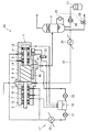
図1に、本発明の第1実施形態のスクリュ圧縮装置1を示す。スクリュ圧縮装置1は、スクリュ圧縮機2で対象気体(例えばプロパンガス)を圧縮して吐出し、潤滑流体分離回収器3によってスクリュ圧縮機2が吐出した対象気体から、スクリュ圧縮機2内の潤滑および冷却のために対象気体混入されているロータ潤滑流体(例えば潤滑油)を分離して、需要設備に圧縮した対象気体を供給するものである。
Embodiments of the present invention will now be described with reference to the drawings.
FIG. 1 shows a
スクリュ圧縮機2は、ハウジング4に形成されたロータ室5の中に、雌雄咬合して回転可能に収容されたスクリュロータ6を有する。スクリュロータ6は、ロータ室5に隣接してハウジング4に形成された軸受空間7,8内に延伸するスクリュ軸9を有し、軸受空間7,8内に配設した軸受9,10によって支持されている。また、雌雄のスクリュロータ9は、吐出側の軸受空間8内において、タイミングギア12によって互いに同期回転するように連結されている。また、スクリュ圧縮機2は、ロータ室5と軸受空間7,8とをそれぞれ隔離するメカニカルシール(シール部材)13,14と、ハウジング4の外にロータ軸9が突出して不図示のモータに接続される吸込側の軸受空間7の開放端を軸封するメカニカルシール15とを有する。さらに、スクリュ圧縮機2は、ロータ室5の吐出側の開口位置を変化させるスライド弁16を有している。
The
また、スクリュ圧縮装置1は、軸受空間7,8に、軸受9,10を潤滑するための軸受潤滑流体(例えば潤滑油)を供給する軸受潤滑システム17を有している。軸受潤滑システム17は、軸受空間7,8から流出した軸受潤滑流体を回収して貯留する供給タンク18と、供給タンク18から軸受潤滑流体を送出する潤滑ポンプ19と、潤滑ポンプ19から吐出された軸受潤滑流体を冷却する冷却器20とを有する。また、スクリュ圧縮装置1は、軸受潤滑流体をスライド弁16を駆動する流体圧シリンダ21の作動媒体としても利用するようになっている。具体的には、スクリュ圧縮装置1は、供給タンク18から軸受潤滑流体を圧送する駆動ポンプ22と、流体圧シリンダ21の2つのポートのいずれに駆動ポンプ22から圧送される軸受潤滑流体を供給するかを選択する3位置切換弁23とを有している。
Further, the
また、スクリュ圧縮装置1は、潤滑流体分離回収器3によって対象気体から分離したロータ潤滑流体を、対象気体の圧力によって、冷却器24を介してスクリュ圧縮機2のロータ室5の吸込部に環流させるロータ潤滑流路25を有している。これにより、ロータ潤滑流体は、スクリュ圧縮装置1の内部で循環する。
Further, the
スクリュ圧縮装置1では、軸受潤滑流体は、メカニカルシール13,14にも供給されている。メカニカルシール13,14は、それぞれ、ハウジング4に気密に固定された2つのステータと、2つのロータの間でロータ軸9に気密に固定され、ロータ軸9と共に回転するロータとからなり、ステータとロータとが互いに摺接し合う。このステータとロータとの摺接面に軸受潤滑流体を供給することで、ステータとロータとの間のシールが完全となり、ロータ室5と軸受空間7,8とがそれぞれ隔離される。なお、メカニカルシール13,14に供給された軸受潤滑流体は、ハウジング4と、ステータとロータとで形成される密閉空間に閉じこめられるので、メカニカルシール13,14からロータ室5や軸受空間7,8に漏出しない。
In the
スクリュ圧縮装置1では、対象気体が軸受空間7,8に侵入しないので、軸受10,11が対象気体の腐食性により浸食されて寿命が短くなるおそれがない。また、軸受潤滑流体は、対象気体およびロータ潤滑流体と接触することがないので、軸受潤滑流体が対象気体によって劣化(粘度低下)させられることがなく、軸受10,11の潤滑および冷却の最適な条件を維持することができる。
In the
なお、本実施形態において、タイミングギア12を省略して、スクリュロータ6同士の咬合によって雌雄のスクリュロータ6を同期回転させてもよい。
In this embodiment, the
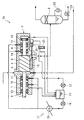
図2に、本発明の第2実施形態のスクリュ圧縮装置1aを示す。なお、これ以降の説明において、先に説明した実施形態と同じ構成要素には、同じ符号を付して重複する説明を省略する。
FIG. 2 shows a
スクリュ圧縮装置1aは、定量式の補給ポンプ26によりリザーバ27から、常に一定量のロータ潤滑流体が供給される。補給ポンプ26からの供給量は、少量であるので、潤滑流体分離回収器3からも、スクリュ圧縮機2にロータ潤滑流体が供給される。潤滑流体分離回収器3は、レベルスイッチ28を有し、その液面が所定範囲に収まるように、滑流体分離回収器3からロータ潤滑流体を排出する排出バルブ29の開度を制御するようになっている。
The
対象気体が例えば腐食性分を含むガスであり、ロータ潤滑流体が潤滑油である場合、スクリュ圧縮装置1の運転に伴い、ロータ潤滑流体に対象気体が少しずつ溶け込んで、ロータ潤滑流体を劣化させる。しかしながら、本実施形態では、新しいロータ潤滑流体が常に供給されるので、ロータ潤滑流体を一定以上の品質に保つことができる。
When the target gas is, for example, a gas containing a corrosive component and the rotor lubricating fluid is lubricating oil, the target gas is gradually dissolved in the rotor lubricating fluid with the operation of the
また、スクリュ圧縮装置1から排出されるロータ潤滑流体は、他のプラントで消費してもよい。例えば、石油精製プラントでは、ロータ潤滑流体として使用し得る液化重炭化水素を消費する。これにより、液化重炭化水素をロータ潤滑流体として使用するスクリュ圧縮装置1から排出したロータ潤滑流体を廃液処理する必要がなくなる。
Moreover, you may consume the rotor lubricating fluid discharged | emitted from the
図3に、本発明の第3実施形態のスクリュ圧縮装置1bを示す。本実施形態では、スクリュ圧縮機2のロータ室5に供給されるロータ潤滑流体は、全量がスクリュ圧縮装置1の外部から供給され、潤滑流体分離回収器3において回収されたロータ潤滑流体は、全てスクリュ圧縮装置1の外部に排出される。
FIG. 3 shows a
例えば、石油精製プラントでは、副生成物として、オクタンのような液化重炭化水素が生成される。通常、これらは、精製処理されるが、本実施形態のスクリュ圧縮装置1bにおいて、ロータ潤滑流体として使用してから、精製処理することで、ロータ潤滑流体に溶け込んだ対象気体も同時に精製処理され、環境汚染の心配がない。
For example, in a petroleum refinery plant, liquefied heavy hydrocarbons such as octane are produced as by-products. Usually, these are refined, but in the
さらに、図4に、本発明の第4実施形態のスクリュ圧縮装置1cを示す。スクリュ圧縮装置1は、ロータ室5と軸受空間7,8との間の軸封のために、カーボンリングシール30,31を備える。また、スクリュ圧縮装置1cは、潤滑流体分離回収器3でロータ潤滑流体を分離した対象気体の一部を、カーボンリングシール30,31の途中に導入している。なお、吸込側のカーボンリングシールには、オリフィス32を介して対象気体を導入することで、その供給量を調整している。
Furthermore, in FIG. 4, the
また、本実施形態では、軸受空間7,8から、軸受潤滑流体だけでなく、カーボンリングシール30,31に供給された対象気体の一部も流出する。これらは、有圧タンク33に回収される。有圧タンク33は、上部空間がスクリュ圧縮機2の吸込側に連通し、上部空間の対象気体がスクリュ圧縮機2の吸込圧によって吸引され、内圧をスクリュ圧縮機2の吸込圧と同じに保つ。また、潤滑ポンプ19から吐出された軸受潤滑流体の一部は、再生装置34を介して有圧タンク33に環流させられ、再生装置34において溶け込んだ対象気体が除去されて、その品質を保つようになっている。
In the present embodiment, not only the bearing lubricating fluid but also part of the target gas supplied to the carbon ring seals 30 and 31 flows out from the bearing
カーボンリングシール30,31は、ロータ軸9との間に微小な隙間を形成する複数のカーボンリング35がハウジング4に気密に保持され、ロータ軸9とカーボンリング35との隙間を対象気体が通過する際の圧損により、通過する対象気体の量を極少量に制限するものである。
In the carbon ring seals 30 and 31, a plurality of carbon rings 35 that form minute gaps between the
また、本実施形態では、カーボンリングシール30,31の途中にロータ室5および軸受空間7,8よりも高圧の対象気体を導入している。これにより、カーボンリングシール30,31の途中に導入した対象気体がロータ室5および軸受空間7,8に流れ込み、ロータ室5からロータ潤滑流体を含んだ対象気体を軸受空間7,8に流入させないので、軸受潤滑流体にロータ潤滑流体が混入することがない。
In the present embodiment, a target gas having a pressure higher than that of the
また、本実施形態において、軸受空間7,8に流入する対象気体は、潤滑流体の搬送媒体ではないため、その流量が非常に少量でよい。よって、本実施形態では、軸受潤滑流体に与える影響は大きくなく、コンパクトな再生装置34で軸受潤滑流体の品質を維持することが可能になっている。
Further, in the present embodiment, the target gas flowing into the bearing
本実施形態では、完全に気密な軸封は、ロータ軸9がハウジング4から突出する部分に設けたメカニカルシール15だけでよい。また、本実施形態のように対象気体と接触する軸受潤滑流体には、米国石油協会の潤滑油システム規格のような厳密な規格が要求されないので、その構造が大きなコスト要因にはならない。
In the present embodiment, a completely airtight shaft seal may be only the
1…スクリュ圧縮装置
2…スクリュ圧縮機
3…潤滑流体分離回収器
4…ハウジング
5…ロータ室
6…スクリュロータ
7,8…軸受室
9…ロータ軸
10,11…軸受
13,14…メカニカルシール(軸封部材)
15…メカニカルシール
16…スライド弁
17…軸受潤滑システム
19…潤滑ポンプ
20…冷却器
21…流体圧シリンダ
24…冷却器
25…ロータ潤滑流路
30,31…カーボンリングシール(軸封部材)
35…カーボンリング
DESCRIPTION OF
DESCRIPTION OF
35 ... carbon ring
Claims (3)
前記スクリュ圧縮機が吐出した前記対象気体から前記ロータ潤滑流体を分離する潤滑流体分離回収器と、
前記軸受空間から流出する軸受潤滑流体を前記軸受空間に環流させる軸受潤滑システムとを有し、
前記軸受潤滑流体は、前記軸封部材にも供給され、
前記軸封部材は、前記ロータ室と前記軸受空間とを複数の狭い隙間を介して接続するように構成され、
前記軸封部材の途中に、前記潤滑流体分離回収器で前記ロータ潤滑流体を分離された前記対象気体の一部が供給されることを特徴とするスクリュ圧縮装置。 A rotor shaft of a screw rotor, which is rotatably accommodated by male and female engagement in a rotor chamber formed in a housing and compresses a target gas together with a rotor lubricating fluid, is placed in a bearing space formed in the housing adjacent to the rotor chamber. A screw compressor provided with a shaft sealing member that is supported by a disposed bearing and that separates the rotor chamber and the bearing space;
A lubricating fluid separation and recovery device for separating the rotor lubricating fluid from the target gas discharged by the screw compressor;
Have a bearing lubrication system for refluxing the bearing lubricating fluid flowing out of the bearing space the bearing space,
The bearing lubricating fluid is also supplied to the shaft seal member,
The shaft seal member is configured to connect the rotor chamber and the bearing space via a plurality of narrow gaps,
A part of the target gas from which the rotor lubricating fluid is separated by the lubricating fluid separating and collecting device is supplied in the middle of the shaft seal member.
前記スクリュ圧縮機が吐出した前記対象気体から前記ロータ潤滑流体を分離する潤滑流体分離回収器と、
前記軸受空間から流出する軸受潤滑流体を前記軸受空間に環流させる軸受潤滑システムとを有し、
前記スクリュ圧縮機は、前記対象気体の前記ロータ室からの吐出位置を制御するスライド弁を備え、
前記軸受潤滑流体は、前記スライド弁の作動媒体を兼ねることを特徴とするスクリュ圧縮装置。 A rotor shaft of a screw rotor, which is rotatably accommodated by male and female engagement in a rotor chamber formed in a housing and compresses a target gas together with a rotor lubricating fluid, is placed in a bearing space formed in the housing adjacent to the rotor chamber. A screw compressor provided with a shaft sealing member that is supported by a disposed bearing and that separates the rotor chamber and the bearing space;
A lubricating fluid separation and recovery device for separating the rotor lubricating fluid from the target gas discharged by the screw compressor;
Have a bearing lubrication system for refluxing the bearing lubricating fluid flowing out of the bearing space the bearing space,
The screw compressor includes a slide valve that controls a discharge position of the target gas from the rotor chamber,
The screw compression device, wherein the bearing lubricating fluid also serves as a working medium of the slide valve.
Priority Applications (7)
| Application Number | Priority Date | Filing Date | Title |
|---|---|---|---|
| JP2008155107A JP4431184B2 (en) | 2008-06-13 | 2008-06-13 | Screw compressor |
| EP09762397.9A EP2306027B1 (en) | 2008-06-13 | 2009-06-03 | Screw compression apparatus |
| CN200980122341.3A CN102066760B (en) | 2008-06-13 | 2009-06-03 | Screw compression apparatus |
| RU2011100838/06A RU2466298C2 (en) | 2008-06-13 | 2009-06-03 | Screw-type compressor unit |
| BRPI0914997-0A BRPI0914997B1 (en) | 2008-06-13 | 2009-06-03 | SCREW COMPRESSION APPLIANCE |
| PCT/JP2009/060120 WO2009150967A1 (en) | 2008-06-13 | 2009-06-03 | Screw compression apparatus |
| US12/995,076 US8512019B2 (en) | 2008-06-13 | 2009-06-03 | Screw compression apparatus |
Applications Claiming Priority (1)
| Application Number | Priority Date | Filing Date | Title |
|---|---|---|---|
| JP2008155107A JP4431184B2 (en) | 2008-06-13 | 2008-06-13 | Screw compressor |
Publications (2)
| Publication Number | Publication Date |
|---|---|
| JP2009299584A JP2009299584A (en) | 2009-12-24 |
| JP4431184B2 true JP4431184B2 (en) | 2010-03-10 |
Family
ID=41416676
Family Applications (1)
| Application Number | Title | Priority Date | Filing Date |
|---|---|---|---|
| JP2008155107A Active JP4431184B2 (en) | 2008-06-13 | 2008-06-13 | Screw compressor |
Country Status (7)
| Country | Link |
|---|---|
| US (1) | US8512019B2 (en) |
| EP (1) | EP2306027B1 (en) |
| JP (1) | JP4431184B2 (en) |
| CN (1) | CN102066760B (en) |
| BR (1) | BRPI0914997B1 (en) |
| RU (1) | RU2466298C2 (en) |
| WO (1) | WO2009150967A1 (en) |
Cited By (1)
| Publication number | Priority date | Publication date | Assignee | Title |
|---|---|---|---|---|
| WO2014041680A1 (en) | 2012-09-14 | 2014-03-20 | 株式会社前川製作所 | Oil-cooled screw compressor system and oil-cooled screw compressor |
Families Citing this family (19)
| Publication number | Priority date | Publication date | Assignee | Title |
|---|---|---|---|---|
| JP5383632B2 (en) * | 2010-11-26 | 2014-01-08 | 株式会社神戸製鋼所 | Screw compressor |
| CN103867449B (en) * | 2012-12-18 | 2016-05-11 | 珠海格力电器股份有限公司 | Compressor oil-supplying system and control method |
| US10415706B2 (en) * | 2013-05-17 | 2019-09-17 | Victor Juchymenko | Methods and systems for sealing rotating equipment such as expanders or compressors |
| JP5950870B2 (en) * | 2013-06-20 | 2016-07-13 | 株式会社神戸製鋼所 | Oil-cooled screw compressor |
| WO2015094465A1 (en) * | 2013-12-18 | 2015-06-25 | Carrier Corporation | Method of improving compressor bearing reliability |
| RU2559411C2 (en) * | 2013-12-26 | 2015-08-10 | Общество с ограниченной ответственностью "Научно-производственное предприятие ВИКОМ-М" | Screw oil-filled compressor unit (versions), and lubrication system of bearings of screw oil-filled compressor unit |
| CN104454462A (en) * | 2014-11-27 | 2015-03-25 | 山东明天机械有限公司 | Circulating water system used for cooling mechanical seals of vapor compressor |
| DE102015007552A1 (en) * | 2015-06-16 | 2016-12-22 | Man Diesel & Turbo Se | Screw machine and method of operating the same |
| WO2017096438A1 (en) * | 2015-12-11 | 2017-06-15 | Atlas Copco Airpower, Naamloze Vennootschap | Method for regulating the liquid injection of a compressor, a liquid-injected compressor and a liquid-injected compressor element |
| DE202016100419U1 (en) | 2016-01-28 | 2017-05-02 | Hugo Vogelsang Maschinenbau Gmbh | Piston for a rotary lobe pump |
| JP6778581B2 (en) * | 2016-10-25 | 2020-11-04 | 株式会社神戸製鋼所 | Oil-free screw compressor |
| DE202016106107U1 (en) * | 2016-10-31 | 2018-02-01 | Hugo Vogelsang Maschinenbau Gmbh | Rotary lobe pump with sealing chamber seal |
| JP6707021B2 (en) * | 2016-12-22 | 2020-06-10 | 株式会社日立産機システム | Screw compressor |
| CN111033004B (en) * | 2017-08-29 | 2022-03-15 | 阿特拉斯·科普柯空气动力股份有限公司 | Machine provided with an oil pump and method for starting such a machine |
| JP6826512B2 (en) * | 2017-09-06 | 2021-02-03 | 株式会社神戸製鋼所 | Compressor |
| CA3016521A1 (en) * | 2017-09-06 | 2019-03-06 | Joy Global Surface Mining Inc | Lubrication system for a compressor |
| JP7146478B2 (en) | 2018-06-22 | 2022-10-04 | 株式会社神戸製鋼所 | Screw compressor and gas compression system |
| EP3742079A1 (en) * | 2019-05-21 | 2020-11-25 | Carrier Corporation | Refrigeration apparatus |
| AU2021202410A1 (en) | 2020-04-21 | 2021-11-11 | Joy Global Surface Mining Inc | Lubrication system for a compressor |
Family Cites Families (16)
| Publication number | Priority date | Publication date | Assignee | Title |
|---|---|---|---|---|
| US2721747A (en) * | 1951-12-21 | 1955-10-25 | Read Standard Corp | Hydraulic shaft seal |
| US3734653A (en) * | 1971-08-23 | 1973-05-22 | S Edstrom | Screw compressor |
| GB1484994A (en) * | 1973-09-03 | 1977-09-08 | Svenska Rotor Maskiner Ab | Shaft seal system for screw compressors |
| SE422349B (en) * | 1977-11-28 | 1982-03-01 | Stal Refrigeration Ab | OIL SEPARATION AT A PLANT TO COMPRESS A GAS |
| DE2948992A1 (en) * | 1979-12-05 | 1981-06-11 | Karl Prof.Dr.-Ing. 3000 Hannover Bammert | ROTOR COMPRESSORS, ESPECIALLY SCREW ROTOR COMPRESSORS, WITH LUBRICANT SUPPLY TO AND LUBRICANT DRAINAGE FROM THE BEARINGS |
| DE3721811A1 (en) | 1987-07-02 | 1989-01-12 | Freudenberg Carl Fa | ENGINE MOUNT |
| SU1714200A1 (en) * | 1990-04-09 | 1992-02-23 | Ленинградский технологический институт холодильной промышленности | Screw compressor |
| US5135374A (en) * | 1990-06-30 | 1992-08-04 | Kabushiki Kaisha Kobe Seiko Sho | Oil flooded screw compressor with thrust compensation control |
| SE503871C2 (en) * | 1994-06-21 | 1996-09-23 | Svenska Rotor Maskiner Ab | Rotary displacement compressor with liquid circulation system |
| JP3803812B2 (en) * | 1996-09-12 | 2006-08-02 | 北越工業株式会社 | Screw rotor |
| JP3456090B2 (en) * | 1996-05-14 | 2003-10-14 | 北越工業株式会社 | Oil-cooled screw compressor |
| BE1010376A3 (en) * | 1996-06-19 | 1998-07-07 | Atlas Copco Airpower Nv | Rotary KOMPRESSOR. |
| JPH1026093A (en) | 1996-07-10 | 1998-01-27 | Kobe Steel Ltd | Oil-cooled displacement type compressor |
| CA2352742A1 (en) * | 1999-01-11 | 2000-07-20 | David Garrett Staat | Screw compressor |
| EP1780416A4 (en) * | 2004-08-03 | 2011-03-09 | Maekawa Seisakusho Kk | Lubricant supply system and operating method of multisystem lubrication screw compressor |
| WO2006091200A1 (en) * | 2005-02-24 | 2006-08-31 | Carrier Corporation | Compressor unloading valve |
-
2008
- 2008-06-13 JP JP2008155107A patent/JP4431184B2/en active Active
-
2009
- 2009-06-03 WO PCT/JP2009/060120 patent/WO2009150967A1/en active Application Filing
- 2009-06-03 BR BRPI0914997-0A patent/BRPI0914997B1/en active IP Right Grant
- 2009-06-03 EP EP09762397.9A patent/EP2306027B1/en active Active
- 2009-06-03 RU RU2011100838/06A patent/RU2466298C2/en active
- 2009-06-03 US US12/995,076 patent/US8512019B2/en active Active
- 2009-06-03 CN CN200980122341.3A patent/CN102066760B/en active Active
Cited By (2)
| Publication number | Priority date | Publication date | Assignee | Title |
|---|---|---|---|---|
| WO2014041680A1 (en) | 2012-09-14 | 2014-03-20 | 株式会社前川製作所 | Oil-cooled screw compressor system and oil-cooled screw compressor |
| US9568001B2 (en) | 2012-09-14 | 2017-02-14 | Mayekawa Mfg. Co., Ltd. | Oil-cooled screw compressor system and oil-cooled screw compressor |
Also Published As
| Publication number | Publication date |
|---|---|
| US20110076174A1 (en) | 2011-03-31 |
| WO2009150967A1 (en) | 2009-12-17 |
| US8512019B2 (en) | 2013-08-20 |
| BRPI0914997A2 (en) | 2015-10-27 |
| CN102066760B (en) | 2014-12-24 |
| EP2306027B1 (en) | 2020-11-18 |
| JP2009299584A (en) | 2009-12-24 |
| CN102066760A (en) | 2011-05-18 |
| EP2306027A1 (en) | 2011-04-06 |
| RU2466298C2 (en) | 2012-11-10 |
| RU2011100838A (en) | 2012-07-20 |
| BRPI0914997B1 (en) | 2020-08-04 |
| EP2306027A4 (en) | 2015-01-21 |
Similar Documents
| Publication | Publication Date | Title |
|---|---|---|
| JP4431184B2 (en) | Screw compressor | |
| EP2314874B1 (en) | Oil-free screw compressor | |
| AU2002244545B2 (en) | Water-injected screw compressor | |
| US4394113A (en) | Lubrication and packing of a rotor-type compressor | |
| US8714910B2 (en) | Compressor unit and assembly method | |
| CN102635553B (en) | Water injection type screw compressor | |
| WO2009107797A1 (en) | Compressor | |
| KR20060051788A (en) | Compressor | |
| JP2008121479A (en) | Hermetic screw compressor | |
| CN1371452A (en) | Closed motor-driven compressor | |
| JP4145830B2 (en) | Oil-cooled compressor | |
| JP2009299632A (en) | Compressor | |
| JP2010121448A (en) | Hermetic compressor | |
| JP2008232005A (en) | Screw compressor | |
| CN114704462A (en) | Screw compressor unit with double lubricating oil ways for working | |
| CN112969857B (en) | Oil-free water injection type screw air compressor | |
| CN113167278B (en) | Screw compressor | |
| JP2000337282A (en) | Two-stage type screw compressor | |
| JP2007024439A (en) | Refrigeration cycle device | |
| JP2002317784A (en) | Rotary two-stage compressor | |
| EP2589810A1 (en) | Rotary compressor | |
| JP4435671B2 (en) | Reciprocating compressor system | |
| JP2005171819A (en) | Refrigerating compressor | |
| JP2006177299A (en) | Electric pump | |
| DE19812819B4 (en) | Screw compressor with mechanical seal shaft seal |
Legal Events
| Date | Code | Title | Description |
|---|---|---|---|
| A521 | Request for written amendment filed |
Free format text: JAPANESE INTERMEDIATE CODE: A523 Effective date: 20091029 |
|
| TRDD | Decision of grant or rejection written | ||
| A01 | Written decision to grant a patent or to grant a registration (utility model) |
Free format text: JAPANESE INTERMEDIATE CODE: A01 Effective date: 20091124 |
|
| A01 | Written decision to grant a patent or to grant a registration (utility model) |
Free format text: JAPANESE INTERMEDIATE CODE: A01 |
|
| A61 | First payment of annual fees (during grant procedure) |
Free format text: JAPANESE INTERMEDIATE CODE: A61 Effective date: 20091218 |
|
| FPAY | Renewal fee payment (event date is renewal date of database) |
Free format text: PAYMENT UNTIL: 20121225 Year of fee payment: 3 |
|
| R150 | Certificate of patent or registration of utility model |
Ref document number: 4431184 Country of ref document: JP Free format text: JAPANESE INTERMEDIATE CODE: R150 Free format text: JAPANESE INTERMEDIATE CODE: R150 |
|
| FPAY | Renewal fee payment (event date is renewal date of database) |
Free format text: PAYMENT UNTIL: 20131225 Year of fee payment: 4 |