JP4430281B2 - Data map creation method, data map creation information recording medium creation method and apparatus - Google Patents
Data map creation method, data map creation information recording medium creation method and apparatus Download PDFInfo
- Publication number
- JP4430281B2 JP4430281B2 JP2002121302A JP2002121302A JP4430281B2 JP 4430281 B2 JP4430281 B2 JP 4430281B2 JP 2002121302 A JP2002121302 A JP 2002121302A JP 2002121302 A JP2002121302 A JP 2002121302A JP 4430281 B2 JP4430281 B2 JP 4430281B2
- Authority
- JP
- Japan
- Prior art keywords
- injection
- correction amount
- map
- data
- correction
- Prior art date
- Legal status (The legal status is an assumption and is not a legal conclusion. Google has not performed a legal analysis and makes no representation as to the accuracy of the status listed.)
- Expired - Lifetime
Links
Images


Classifications
-
- F—MECHANICAL ENGINEERING; LIGHTING; HEATING; WEAPONS; BLASTING
- F02—COMBUSTION ENGINES; HOT-GAS OR COMBUSTION-PRODUCT ENGINE PLANTS
- F02D—CONTROLLING COMBUSTION ENGINES
- F02D41/00—Electrical control of supply of combustible mixture or its constituents
- F02D41/24—Electrical control of supply of combustible mixture or its constituents characterised by the use of digital means
- F02D41/2406—Electrical control of supply of combustible mixture or its constituents characterised by the use of digital means using essentially read only memories
- F02D41/2425—Particular ways of programming the data
-
- F—MECHANICAL ENGINEERING; LIGHTING; HEATING; WEAPONS; BLASTING
- F02—COMBUSTION ENGINES; HOT-GAS OR COMBUSTION-PRODUCT ENGINE PLANTS
- F02D—CONTROLLING COMBUSTION ENGINES
- F02D41/00—Electrical control of supply of combustible mixture or its constituents
- F02D41/24—Electrical control of supply of combustible mixture or its constituents characterised by the use of digital means
- F02D41/2406—Electrical control of supply of combustible mixture or its constituents characterised by the use of digital means using essentially read only memories
- F02D41/2409—Addressing techniques specially adapted therefor
- F02D41/2416—Interpolation techniques
-
- F—MECHANICAL ENGINEERING; LIGHTING; HEATING; WEAPONS; BLASTING
- F02—COMBUSTION ENGINES; HOT-GAS OR COMBUSTION-PRODUCT ENGINE PLANTS
- F02D—CONTROLLING COMBUSTION ENGINES
- F02D41/00—Electrical control of supply of combustible mixture or its constituents
- F02D41/24—Electrical control of supply of combustible mixture or its constituents characterised by the use of digital means
- F02D41/2406—Electrical control of supply of combustible mixture or its constituents characterised by the use of digital means using essentially read only memories
- F02D41/2425—Particular ways of programming the data
- F02D41/2429—Methods of calibrating or learning
- F02D41/2451—Methods of calibrating or learning characterised by what is learned or calibrated
- F02D41/2464—Characteristics of actuators
- F02D41/2467—Characteristics of actuators for injectors
-
- F—MECHANICAL ENGINEERING; LIGHTING; HEATING; WEAPONS; BLASTING
- F02—COMBUSTION ENGINES; HOT-GAS OR COMBUSTION-PRODUCT ENGINE PLANTS
- F02D—CONTROLLING COMBUSTION ENGINES
- F02D41/00—Electrical control of supply of combustible mixture or its constituents
- F02D41/24—Electrical control of supply of combustible mixture or its constituents characterised by the use of digital means
- F02D41/2406—Electrical control of supply of combustible mixture or its constituents characterised by the use of digital means using essentially read only memories
- F02D41/2425—Particular ways of programming the data
- F02D41/2429—Methods of calibrating or learning
- F02D41/2432—Methods of calibration
- F02D41/2435—Methods of calibration characterised by the writing medium, e.g. bar code
Description
【0001】
【発明の属する技術分野】
本発明は、データマップ作成方法、データマップ作成用情報記録媒体作成方法及びこれらの装置に関する。
【0002】
【従来の技術】
例えば、ディーゼルエンジンの燃料噴射弁においては、噴射量のばらつきを補正するために、各燃料噴射弁について、予めいくつかの燃料圧力値に対して目標とする噴射量に必要な噴射期間を複数点にわたって測定して、標準の燃料噴射弁との噴射期間のずれを補正値として求めている。この補正値は、例えば2次元コード化して各燃料噴射弁に取り付けられて、ディーゼルエンジンの組み立て部門に移送されている。
【0003】
組み立て部門では、燃料噴射弁を各気筒に取り付ける場合に、燃料噴射弁に取り付けられた2次元コードの内容を読み取り、得られた補正値を燃料圧力と噴射期間とをパラメータとするマップに構成して、ECU(電子制御ユニット)内のメモリに記憶させて、各燃料噴射弁の燃料噴射量制御に用いている。
【0004】
【発明が解決しようとする課題】
しかし組み立て対象となるディーゼルエンジンの種類に応じて燃料噴射弁に対する性能要求が異なり、このような要求に応じて特性の異なる各種の燃料噴射弁が存在する。このような特性の違いにより、前記補正値からなるマップにおいては、低密度の補正点でも高精度な制御ができる領域と、高密度に補正点を設けないと制御上のずれが大きくなって高精度な制御ができない領域とが燃料噴射弁の種類によって異なることがある。
【0005】
このように補正点が低密度でも良い領域と、高密度にする必要がある領域とが燃料噴射弁の種類により異なる場合を考慮すると、燃料圧力と噴射期間との空間全体に対して高密度に補正点を配置する必要がある。
【0006】
しかし、燃料噴射弁に取り付け可能な2次元コードのような情報記録媒体では記録できる情報量が限られており、すべての種類の燃料噴射弁に適合するように高密度の補正点に対応した多数の補正値を記憶することができない。
【0007】
又、たとえ多数の補正値を記憶できる情報記録媒体を用いることができたとしても、予め多数のデータを測定して補正値を求める必要がある。そしてこの多数の補正値を情報記録媒体に記憶し、更にディーゼルエンジンへ燃料噴射弁を組み込む際に、多数の補正値を情報記録媒体から読み出してECUのメモリに記憶させる必要がある。このため作業的にも装置的にも高コスト化するおそれがある。
【0008】
このようなことは、ディーゼルエンジンの燃料噴射弁に限らず、他のエンジンの燃料噴射弁や、各種センサ類の検出値の補正など他の機構の作動管理においても同じである。
【0009】
本発明は、少ないデータ量にても機構の種類別に高精度なデータマップが利用できるようにすることを目的とするものである。
【0010】
【課題を解決するための手段】
以下、上記目的を達成するための手段及びその作用効果について記載する。
請求項1に記載のデータマップ作成方法は、情報記録媒体から噴射補正量データを読み出して、その読み出した噴射補正量データをマップ上に振り分けることで噴射補正量マップを形成する方法であって、前記情報記録媒体には、前記噴射補正量データをインデックス順に配列した噴射補正量データ配列が記録され、前記噴射補正量マップは、燃料圧力値を第1インデックスとし、噴射期間の長さを第2インデックスとする2次元配列として形成されて、燃料噴射弁の個体毎の燃料噴射期間のばらつきの補正データが格納されるとともに、前記噴射補正量マップの第1インデックスと同数の第1インデックスと同噴射補正量マップの第2インデックスと同数の第2インデックスとからなる2次元配列として形成され、且つその2次元配列中に前記噴射補正量データ配列のインデックスが配置された振り分けマップを、前記燃料圧力値及び前記噴射期間の内の一方のパラメータの各構成点において前記燃料噴射補正量の振り分けを必要とする他方のパラメータの構成点の数を変更することで、適用される種類の燃料噴射弁の特性に対応して燃料噴射弁の種類別に形成する行程と、燃料噴射期間のばらつきを計測するとともに、その計測結果から得られた噴射補正量データをインデックス順に配列した噴射補正量データ配列を形成し、そのデータ配列を情報記録媒体に記録する行程と、を備え、前記情報記録媒体から噴射補正量データを読み込む行程と、その読み込んだ噴射補正量データを書き込む前記噴射補正量マップのマップ位置を、前記振り分けマップから算出する行程と、噴射補正量データをその算出したマップ位置に書き込む行程と、を前記情報記録媒体に記録された噴射補正量データのそれぞれについて行うことで前記噴射補正量マップを形成することを特徴とする。
【0012】
したがって、少ないデータ量でも、機構の種類に対応した密度分布でデータを配置したマップを作成でき、機構の種類別に高精度なデータマップが利用できるようになる。
【0020】
請求項2に記載のデータマップ作成方法では、請求項1において、前記情報記録媒体は2次元コードであることを特徴とする。
2次元コードのような情報記録媒体は、記録できる情報量が限られており、すべての種類の燃料噴射弁に適合するように高密度の補正点に対応した多数の補正値を記憶することができない。しかし請求項1〜4のいずれかに記載のごとく構成することにより、2次元コードに記録できる少ないデータ量でも、機構の種類に対応した密度分布でデータを配置したマップを作成でき、機構の種類別に高精度なデータマップが利用できるようになる。
【0021】
請求項6に記載のデータマップ作成用情報記録媒体作成方法は、燃料圧力値を第1インデックスとし、噴射期間の長さを第2インデックスとする2次元配列として形成されて、燃料噴射弁の個体毎の燃料噴射期間のばらつきの補正データが格納された噴射補正量マップを形成するための噴射補正量データを情報記録媒体に記録する方法であって、燃料圧力値及び噴射期間の長さの2つのパラメータの内の一つのパラメータの各構成点において測定を必要とする他のパラメータの構成点の数を変更するとともに、その変更の態様を種類別に異ならせることで燃料噴射弁の種類に対応した測定点の設定を行う第1の行程と、設定された各測定点において燃料噴射期間のばらつきを測定する第2の行程と、測定された燃料噴射期間のばらつきに基づいて噴射補正量データをインデックス順に配列した噴射補正量データ配列を形成し、前記情報記録媒体に記録する第3の行程と、を備えるとともに、前記第1の行程は、サンプリングした複数の燃料噴射弁のそれぞれについて予め設定した標準測定点にて噴射期間補正量の測定を行うとともに、その測定した各標準補正点の噴射期間補正量の平均値を算出する第4の行程と、各標準補正点の噴射期間補正量の平均値を最小二乗法を用いて単数又は複数の直線に近似するとともに、その近似した単数又は複数の直線と前記平均値との誤差が許容範囲内に収まる最小の直線数を求め、その最小数の直線を表すことのできる最小の標準測定点を残して残りの標準測定点を補正候補から除外することで、補正候補点の減数化を実行する第5の行程と、前記補正候補点の数が前記噴射補正量データ配列のインデックス数以内であるか否かを確認する第6の行程と、前記前記補正候補点の数が前記噴射補正量データ配列のインデックス数以内となるまで、前記許容範囲を順次大きくしていきながら前記第5の行程を繰り返し実行する第7の行程と、を備えることを特徴とする。
【0030】
請求項4に記載のデータマップ作成用情報記録媒体作成方法では、請求項3において、前記情報記録媒体は2次元コードであることを特徴とする。
【0031】
2次元コードのような情報記録媒体は、記録できる情報量が限られており、すべての種類の燃料噴射弁に適合するように高密度の補正点に対応した多数の補正値を記憶することができない。しかし請求項3に記載のごとく前記測定点情報を用いて得られたデータならば、2次元コードに記録させることができるようなデータ量でも機構の種類に対応した密度分布でデータを配置したマップを作成でき、機構の種類別に高精度なデータマップが利用できるようになる。
【0036】
請求項5に記載のデータマップ作成装置は、情報記録媒体から噴射補正量データを読み出して、その読み出した噴射補正量データをマップ上に振り分けることで噴射補正量マップを形成する装置であって、前記情報記録媒体には、前記噴射補正量データをインデックス順に配列した噴射補正量データ配列が記録され、前記噴射補正量マップは、燃料圧力値を第1インデックスとし、噴射期間の長さを第2インデックスとする2次元配列として形成されて、燃料噴射弁の個体毎の燃料噴射期間のばらつきの補正データが格納されるとともに、前記情報記録媒体から噴射補正量データを読み出す媒体データ読み出し手段と、前記噴射補正量マップの第1インデックスと同数の第1インデックスと同噴射補正量マップの第2インデックスと同数の第2インデックスとからなる2次元配列として形成され、且つその2次元配列中に前記噴射補正量データ配列のインデックスが配置された振り分けマップを、前記燃料圧力値及び前記噴射期間の内の一方のパラメータの各構成点において前記燃料噴射補正量の振り分けを必要とする他方のパラメータの構成点の数を変更することで、適用される種類の燃料噴射弁の特性に対応して燃料噴射弁の種類別に形成したものを記憶する振り分け情報記憶手段と、前記情報記録媒体から読み込んだ噴射補正量データのそれぞれについて、各噴射補正量データを書き込む前記噴射補正量マップのマップ位置を、前記振り分けマップから算出するとともに、その算出したマップ位置に読み込んだ噴射補正量データを書き込むことで、各噴射補正量データの前記噴射補正量マップ上への振り分けを行うことで前記噴射補正量マップを形成するデータ振り分け手段と、を備えたことを特徴とする。
【0046】
請求項6に記載のデータマップ作成装置では、請求項5において、前記情報記録媒体は2次元コードであることを特徴とする。
2次元コードのような情報記録媒体は、記録できる情報量が限られており、すべての種類の燃料噴射弁に適合するように高密度の補正点に対応した多数の補正値を記憶することができない。しかし請求項5に記載のごとく構成することにより、2次元コードに記録できる少ないデータ量でも、機構の種類に対応した密度分布でデータを配置したマップを作成でき、機構の種類別に高精度なデータマップが利用できるようになる。
【0047】
請求項7に記載のデータマップ作成用情報記録媒体作成装置は、燃料圧力値を第1インデックスとし、噴射期間の長さを第2インデックスとする2次元配列として形成されて、燃料噴射弁の個体毎の燃料噴射期間のばらつきの補正データが格納された噴射補正量マップを形成するための噴射補正量データを情報記録媒体に記録する装置であって、燃料圧力値及び噴射期間の長さの2つのパラメータの内の一つのパラメータの各構成点において測定を必要とする他のパラメータの構成点の数を変更するとともに、その変更の態様を種類別に異ならせることで燃料噴射弁の種類に対応して設定された測定点の情報を記憶する測定点情報記憶手段と、前記測定点情報記憶手段にて記憶された測定点情報に基づく各測定点において燃料噴射期間のばらつきを測定する測定手段と、測定された燃料噴射期間のばらつきに基づいて、噴射補正量データをインデックス順に配列した噴射補正量データ配列をマップ形成用データとして設定するマップ形成用データ設定手段と、前記測定点情報記憶手段にて記憶された測定点情報と前記マップ形成用データの各噴射補正量データとの関係を表した配列情報を記憶する配列情報記憶手段と、前記マップ形成用データを、前記配列情報に基づく配列にて前記情報記録媒体に記録するマップ形成用データ記録手段と、を備え、前記測定点情報記憶手段に記憶される各測定点が、サンプリングした複数の燃料噴射弁のそれぞれについて予め設定した標準測定点にて噴射期間補正量の測定を行うとともに、その測定した各標準補正点の噴射期間補正量の平均値を算出すること、各標準補正点の噴射期間補正量の平均値を最小二乗法を用いて単数又は複数の直線に近似するとともに、その近似した単数又は複数の直線と前記平均値との誤差が許容範囲内に収まる最小の直線数を求め、その最小数の直線を表すことのできる最小の標準測定点を残して残りの標準測定点を補正候補から除外することで、補正候補点の減数化を実行すること、前記補正候補点の数が前記噴射補正量データ配列のインデックス数以内であるか否かを確認すること、及び前記前記補正候補点の数が前記噴射補正量データ配列のインデックス数以内となるまで、前記許容範囲を順次大きくしていきながら前記補正候補点の減数化を繰り返し実行すること、を通じて設定されることを特徴とする。
【0057】
請求項8に記載のデータマップ作成用情報記録媒体作成装置では、請求項7において、前記情報記録媒体は2次元コードであることを特徴とする。
【0058】
2次元コードのような情報記録媒体は、記録できる情報量が限られており、すべての種類の燃料噴射弁に適合するように高密度の補正点に対応した多数の補正値を記憶することができない。しかし請求項7に記載のごとく前記測定点情報を用いて得られたデータならば、2次元コードに記録させることができるようなデータ量でも機構の種類に対応した密度分布でデータを配置したマップを作成でき、機構の種類別に高精度なデータマップが利用できるようになる。
【0063】
【発明の実施の形態】
[実施の形態1]
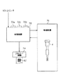
図1は、蓄圧式ディーゼルエンジン(コモンレール型ディーゼルエンジン)2とその制御系統を示す概略構成図である。本蓄圧式ディーゼルエンジン2は自動車用エンジンとして車両に搭載されているものである。尚、このディーゼルエンジン2の制御系統を構成している電子制御装置(ECU)3に設けられたROMには、後述するROM書き込み処理(図12)により作成された噴射補正量マップ(図3〜6)が記憶されている。
【0064】
まず、ディーゼルエンジン2について説明する。このディーゼルエンジン2は、複数の気筒(本実施の形態では4気筒であるが、1気筒のみ図示している)♯1,#2,#3,♯4が設けられており、各気筒♯1〜♯4の燃焼室に対して燃料噴射弁4(後述する4a〜4dに相当)がそれぞれ設けられている。燃料噴射弁4からディーゼルエンジン2の各気筒♯1〜♯4への燃料噴射は、噴射制御用の各電磁弁5のオン・オフにより制御される。
【0065】
燃料噴射弁4は、各気筒共通の蓄圧配管としてのコモンレール6に接続されており、前記噴射制御用の電磁弁5が開いている間、すなわち噴射期間の間にコモンレール6内の燃料が燃料噴射弁4より各気筒♯1〜♯4内に噴射される。前記コモンレール6には、燃料噴射のための比較的高い燃料圧力が蓄積されている。この蓄圧を実現するために、コモンレール6は供給配管8を介してサプライポンプ10の吐出ポート10aに接続されている。又、供給配管8の途中には、逆止弁8aが設けられている。この逆止弁8aの存在により、サプライポンプ10からコモンレール6への燃料の供給が許容され、かつコモンレール6からサプライポンプ10への燃料の逆流が阻止されている。
【0066】
サプライポンプ10は、吸入ポート10bを介して燃料タンク12に接続されており、その途中にはフィルタ14が設けられている。サプライポンプ10は、燃料タンク12からフィルタ14を介して燃料を吸入する。又、これとともに、サプライポンプ10は、ディーゼルエンジン2の回転に同期する図示していないカムによってプランジャを往復運動させて、燃料圧力を要求される噴射圧にまで高めて、この高圧燃料をコモンレール6に供給している。
【0067】
更にサプライポンプ10の吐出ポート10a近傍には、圧力制御弁10cが設けられている。この圧力制御弁10cは、吐出ポート10aからコモンレール6の方へ吐出される燃料圧力を制御するためのものである。この圧力制御弁10cが開かれることにより、吐出ポート10aから吐出されない分の余剰燃料が、サプライポンプ10に設けられたリターンポート10dからリターン配管16を経て燃料タンク12へと戻されるようになっている。
【0068】
ディーゼルエンジン2の各気筒♯1〜♯4の燃焼室には、吸気通路18および排気通路20がそれぞれ接続されている。吸気通路18には図示していないスロットルバルブが設けられており、このスロットルバルブをディーゼルエンジン2の運転状態により開度調整することにより、燃焼室内に導入される吸入空気の流量が調整される。
【0069】
又、ディーゼルエンジン2の各気筒♯1〜♯4の燃焼室内には、グロープラグ22が配設されている。このグロープラグ22は、ディーゼルエンジン2の始動直前にグローリレー22aを介して電流が流されることにより赤熱し、これに燃料噴霧の一部が吹きつけられることで着火・燃焼が促進される始動補助装置である。
【0070】
ディーゼルエンジン2には、以下の各種センサ等が設けられており、これらは、本実施の形態1において、ディーゼルエンジン2の運転状態を検出するものである。すなわち、図1に示すように、アクセルペダル24の近傍には、アクセル開度ACCPFを検出するためのアクセルセンサ26が設けられている。又、ディーゼルエンジン2には、ディーゼルエンジン2を始動させるためのスタータ30が設けられている。このスタータ30には、その作動状態を検知するスタータスイッチ30aが設けられている。ディーゼルエンジン2のシリンダブロックには、その冷却水の温度(冷却水温THW)を検出するための水温センサ32が設けられている。更にオイルパン(図示略)にはエンジンオイルの温度THOを検出する油温センサ34が設けられている。また前記リターン配管16には、燃料温度THFを検出するための燃温センサ36が設けられている。又、前記コモンレール6にはコモンレール6内の燃料圧力Pfを検出するために燃圧センサ38が設けられている。ディーゼルエンジン2のクランクシャフト(図示略)に設けられたパルサ(図示略)の近傍には、NEセンサ40が設けられている。更にクランクシャフトの回転は、吸気弁18aおよび排気弁20aを開閉動作させるためのカムシャフト(図示略)にタイミングベルト等を介して伝達される。このカムシャフトは、クランクシャフトの1/2回転の回転速度で回転するよう設定されている。このカムシャフトに設けられたパルサ(図示略)の近傍には、気筒判別センサ42が設けられている。そして、本実施の形態1ではこれら両センサ40,42から出力されるパルス信号により、エンジン回転数NE、クランク角CA、第1気筒♯1の吸気上死点(TDC)が算出されている。トランスミッション44には、シフトポジションセンサ46が設けられて、トランスミッション44のシフト状態を検出している。またトランスミッション44の出力軸側には、出力軸の回転数から車速SPDを検出する車速センサ48が設けられている。またディーゼルエンジン2の出力により駆動するエアコン装置(図示略)が設けられるとともに、このエアコン装置の駆動を指示するためのエアコンスイッチ50が設けられている。
【0071】
前述したECU3は、ディーゼルエンジン2の各種制御を司るために設けられており、このECU3により、燃料噴射弁4の開弁期間の調整による燃料噴射量制御やグロー通電制御等のディーゼルエンジン2を制御するための処理等が行われる。ECU3は、中央処理制御装置(CPU)、各種プログラムや噴射補正量マップ等を予め記憶した読出専用メモリ(ROM)、CPUの演算結果等を一時記憶するランダムアクセスメモリ(RAM)、演算結果や予め記憶されたデータ等を保存するバックアップRAM、タイマカウンタ、入力インターフェース、出力インターフェース等を備えたマイクロコンピュータを中心として構成されている。
【0072】
前述したアクセルセンサ26、水温センサ32、油温センサ34、燃温センサ36、燃圧センサ38等は、それぞれバッファ、マルチプレクサ、A/D変換器(いずれも図示せず)を介してECU3の入力インターフェースに接続されている。又、NEセンサ40、気筒判別センサ42、車速センサ48等は、波形整形回路(図示せず)を介してECU3の入力インターフェースに接続されている。さらにスタータスイッチ30a、シフトポジションセンサ46、エアコンスイッチ50等はECU3の入力インターフェースに直接接続されている。これ以外にバッテリ電圧VBおよびオルタネータの制御デューティDF等がECU3に入力されて、その値が読み込まれている。
【0073】
CPUは、上記各センサやスイッチ類の信号を入力インターフェースを介して読み込む。また電磁弁5、圧力制御弁10c、グローリレー22a等は、それぞれ駆動回路を介してECU3の出力インターフェースに接続されている。CPUは、入力インターフェースを介して読み込んだ入力値に基づき制御演算を行い、出力インターフェースを介して前記電磁弁5、圧力制御弁10c、グローリレー22a等を制御する。このことにより、後述するごとく運転状態に応じた燃料噴射量が高精度に調整されて燃料噴射弁4から噴射され、又、始動時でのグローリレー22aによる発熱等が運転状態に応じて行われる。
【0074】
次に、本実施の形態において、ECU3により実行される制御処理の内、燃料噴射量制御処理について説明する。図2は燃料噴射量制御処理を示している。本処理は一定クランク角毎(爆発行程毎)の割り込みで実行される。なお個々の処理に対応するフローチャート中のステップを「S〜」で表す。
【0075】
本処理が開始されると、まず前述したセンサ類によりディーゼルエンジン2の運転状態が読み込まれる(S100)。そして今回の処理に基づいて燃料噴射タイミングとなる気筒番号(#)を、メモリ上に設けた変数iに設定する(S102)。そしてステップS100にて読み込んだ運転状態に基づいて演算処理を実行して、最終基本噴射量QFINCを算出する(S104)。
【0076】
この最終基本噴射量QFINCの算出処理は、アイドル時においては、アイドル目標回転数が実現されるように噴射量が増減計算されることで、最終基本噴射量QFINCに反映されるよう計算される。又、アイドル時以外においては、アクセル開度ACCPFによる運転者の指示に応じたトルクを出力するようにエンジン回転数NE等を考慮して噴射量が増減計算されることで、最終基本噴射量QFINCに反映されるよう計算される。
【0077】
次にパイロット要求噴射量QPLがディーゼルエンジン2の運転状態に基づいて算出される(S106)。そして最終基本噴射量QFINCからパイロット要求噴射量QPLを減算「QFINC−QPL」することにより、メイン要求噴射量QMFを算出する(S108)。
【0078】
このように算出されたメイン要求噴射量QMFと、燃圧センサ38にて検出されている燃料圧力Pfとに基づいて、マップあるいは関数により、補正前メイン噴射期間TQMが算出される(S110)。
【0079】
そして次に補正前メイン噴射期間TQMと燃料圧力Pfとに基づいて、マップにより、#i気筒の燃料噴射弁4についてのメイン噴射補正量dtqmを算出する(S112)。この算出は、図3〜6に示す#1〜#4気筒のマップの内、該当する気筒の噴射補正量マップを用いて次のごとくになされる。
【0080】
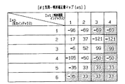
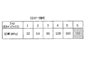
まず図3〜6に示した噴射補正量マップの構成について説明する。図3〜6に示した各噴射補正量マップは、2次元配列としてECU3のROM内に記憶されている。第1インデックスIxpは圧力インデックスであり、第2インデックスIxtは噴射期間インデックスである。第1インデックスIxpについては「1」〜「6」が存在し、図7の1次元配列に示すごとくの燃料圧力値(MPa)に相当する。この図7の1次元配列もECU3のROM内に記憶されている。
【0081】
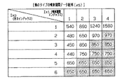
更に、各第1インデックスIxpに対する第2インデックスIxtについては、「1」〜「4」が存在し、図8の2次元配列に示すごとくの噴射期間の長さ(μs)に相当する。この図8の2次元配列もECU3のROM内に記憶されている。
【0082】
例えば、ここでi=1であるとすると、メイン噴射補正量dtqmの計算においては図3に示す#1気筒の噴射補正量マップを用いることになる。まず燃圧センサ38にて測定されている燃料圧力Pfに基づいて、第1インデックスIxpの内で圧力が小さい側と大きい側とでそれぞれ隣接する燃料圧力値の2つの第1インデックスIxp1,Ixp2を抽出する。そしてこの2つ第1インデックスIxp1,Ixp2のそれぞれにおいて、補正前メイン噴射期間TQMに基づいて第2インデックスIxtの内で噴射期間が短い側と長い側とでそれぞれ隣接する噴射期間の4つの第2インデックスIxt11,Ixt12,Ixt21,Ixt22を抽出する。
【0083】
これらの配置状態を図9に示す。マーク○が今回求められた燃料圧力Pfと補正前メイン噴射期間TQMとを示す位置であり、マーク□が抽出されたインデックスが該当する4カ所[Ixp1,Ixt11]、[Ixp1,Ixt12]、[Ixp2,Ixt21]、[Ixp2,Ixt21]、を示している。例えば、燃料圧力Pf=72MPaであり、補正前メイン噴射期間TQM=810μsとする。Pf=72MPaの位置は、図3においては第1インデックスIxp=「2」と「3」との間である。更に、TQM=810μsの位置は、第1インデックスIxp=「2」では第2インデックスIxt=「2」と「3」との間であり、第1インデックスIxp=「3」では第2インデックスIxt=「2」と「3」との間である。尚、図3において丸括弧内の数値は具体的な噴射補正量の値を示している。
【0084】
そして第1インデックスIxp1側で、第2インデックスIxt11,Ixt12におけるマップ値から、補間計算により補正前メイン噴射期間TQMに対応する第1補間補正量X1(マーク△)を算出する。例えば、次式1のごとく算出される。
【0085】
【数1】
X1 ← {(db−da)/(tb−ta)}(TQM−ta)+da… [式1]
ここで噴射期間taは第2インデックスIxt11における噴射期間であり、噴射期間tbは第2インデックスIxt12における噴射期間である。又、噴射補正量daは第2インデックスIxt11における噴射補正量(ここでは図3に示す#1気筒の噴射補正量=37μs)であり、噴射補正量dbは第2インデックスIxt12における噴射補正量(同じく図3に示す#1気筒の噴射補正量=−121μs)である。
【0086】
同様にして、第1インデックスIxp2側で、第2インデックスIxt21,Ixt22におけるマップ値から、前記式1と同様の補間計算により補正前メイン噴射期間TQMに対応する第1補間補正量X2(マーク△)を求める。すなわち、次式2のごとく算出される。
【0087】
【数2】
X2 ← {(dd−dc)/(td−tc)}(TQM−tc)+dc… [式2]
ここで噴射期間tcは第2インデックスIxt21における噴射期間であり、噴射期間tdは第2インデックスIxt22における噴射期間である。又、噴射補正量dcは第2インデックスIxt21における噴射補正量(ここでは図3に示す#1気筒の噴射補正量=52μs)であり、噴射補正量ddは第2インデックスIxt22における噴射補正量(同じく図3に示す#1気筒の噴射補正量=99μs)である。
【0088】
そして上述のごとく算出された2つの第1補間補正量X1,X2を用いて、補間計算により、今回の燃料圧力Pfに対応する補間補正量であるメイン噴射補正量dtqmを求める。例えば次式3のごとく算出される。
【0089】
【数3】
dtqm ← {(X2−X1)/(pb−pa)}(Pf−pa)+X1… [式3]
前述したごとく、Pf=72MPa、TQM=810μsであるとすると、上述した計算により、X1=−42μs、X2=91μs、dtqm=−10μsが算出される。
【0090】
尚、図9に示した例は、第1インデックスIxp1,Ixp2にて共に、該当する第2インデックスIxtが2つずつ存在したが、隣接する第2インデックスIxtが1つしか存在しない場合には、補間補正量X1,X2には、その1つの第2インデックスIxtに対応する噴射補正量の値がそのまま設定される。又、第1インデックスIxp1,Ixp2を併せても、隣接する第2インデックスIxtが1つしか存在しない場合には、メイン噴射補正量dtqmにはその1つの第2インデックスIxtに対応する噴射補正量の値がそのまま設定される。
【0091】
このようにしてステップS112にてメイン噴射補正量dtqmが求められると、次式4のごとく、補正前メイン噴射期間TQMが補正されてメイン噴射期間TQMFが算出される(S114)。
【0092】
【数4】
TQMF ← TQM + dtqm … [式4]
次にステップS106にて算出されたパイロット要求噴射量QPLと、燃圧センサ38にて検出されている燃料圧力Pfとに基づいて、マップあるいは関数により、補正前パイロット噴射期間TQPが算出される(S116)。
【0093】
そして次に補正前パイロット噴射期間TQPと燃料圧力Pfとに基づいて、前述した噴射補正量マップ(図3〜6)により、#i気筒の燃料噴射弁4についてのパイロット噴射補正量dtqpを算出する(S118)。この算出は、補正前メイン噴射期間TQMの代わりに補正前パイロット噴射期間TQPを用いることで、前述したメイン噴射補正量dtqmの算出と同様に実行される。
【0094】
こうしてパイロット噴射補正量dtqpが求められると、次式5のごとく、補正前パイロット噴射期間TQPが補正されてパイロット噴射期間TQPLが算出される(S120)。
【0095】
【数5】
TQPL ← TQP + dtqp … [式5]
こうして一旦本処理を終了する。このような噴射補正量マップ(図3〜6)を用いた燃料噴射量制御処理を繰り返すことにより、各気筒の個々の燃料噴射弁4の噴射量ばらつきの違いに対応して高精度に燃料噴射量を調整することが可能となる。
【0096】
次に、ECU3のROMに対する噴射補正量マップ(図3〜6)の作成処理について説明する。ECU3のROM(実際には書き込み可能なEPROM、EEPROM、フラッシュメモリ等を使用)への書き込みは、ディーゼルエンジン2の各気筒に対して燃料噴射弁4を組み付ける時になされる。
【0097】
燃料噴射弁4(4a,4b,4c,4d)の組み付け時における噴射補正量マップ作成システムの概略構成を図10に示す。ここで燃料噴射弁4aは#1気筒に、燃料噴射弁4bは#2気筒に、燃料噴射弁4cは#3気筒に、燃料噴射弁4dは#4気筒に取り付けられるものとする。
【0098】
燃料噴射弁4a〜4dをディーゼルエンジン2に組み付ける時には、ECU3には書き込み装置60が取り付けられている。又、各燃料噴射弁4a〜4dには、それぞれ2次元コード62a,62b,62c,62dが既にシール紙に印刷されて取り付けられている。
【0099】
ここで#1〜#4気筒の燃料噴射弁4a〜4dに取り付けられている2次元コード62a〜62dには、図11に示すごとく、それぞれ各1バイトからなる12個の噴射補正量データ配列が記載されている。このデータ配列は前記図8に示したハッチング以外の燃料圧力と噴射期間にて各燃料噴射弁4a〜4dの燃料噴射期間のばらつきを計測して後述する図13の振り分けマップに記載のインデックス順に配列したものである。尚、図11では、各データが1バイトであることを示すために16進数で示している。ただし、この16進数は符号付きの16進数であるので、10進数では「−128〜127」までの範囲を表すことができる。更に各2次元コード62a〜62dには、図示していないがこれらの燃料噴射弁4a〜4dが組み込まれるディーゼルエンジン2の機種コードが記載されている。この機種コードにより、組み込まれる燃料噴射弁の種類が決定できる。
【0100】
組み立て作業者は、書き込み装置60に対してキー入力や2次元コードリーダ60aから#1気筒に対する作業であることを知らせた後、2次元コードリーダ60aにて#1気筒に組み込む(あるいは既に組み込んだ)燃料噴射弁4aに取り付けられている2次元コード62aの内容を読み取る。このことにより書き込み装置60は、ECU3内部のROMに書き込ませるために、#1気筒用のデータとして、読み取った機種コードと12個の噴射補正量データとをECU3へ送信する。
【0101】
このことにより、ECU3側では内部に設けられたROM書き込み機能を利用して、図12に示すROM書き込み処理が行われる。
図12のROM書き込み処理について説明する。本処理は書き込み装置60がECU3に接続され、かつ書き込み装置60からECU3へデータが入力されることにより実行される処理である。
【0102】
書き込み装置60から最初に、#1気筒を示すデータと、#1気筒の燃料噴射弁4aに取り付けられている2次元コード62aの内容を読み込んだデータとが送信されて来ると、ECU3はこれらのデータをRAM内に設けられたバッファに格納する。そしてこのことにより、ROM書き込み処理(図12)が開始される。まずバッファに格納している一連のデータを検索して、このデータ内に記載されている機種コードが本ディーゼルエンジン2に対応するものであるか否かを判定する(S202)。ECU3内のROMには予め本ディーゼルエンジン2の機種コードが記載されていることから、この機種コードと受信した機種コードが一致しているか否かを判定する。
【0103】
機種コードが一致していない場合には(S202で「NO」)、燃料噴射弁4aが本ディーゼルエンジン2に用いられるものではないことが判明するので、エラー出力をして(S204)、書き込み装置60側に燃料噴射弁4aが適切なものではないことを送信する。書き込み装置60側では、例えば、ディスプレイや表示ランプにより作業者に機種コードの違いを警告することになる。
【0104】
そしてRAM内のバッファに存在する受信データを消去して(S206)、次のデータが送信されるまで、本処理を終了する。
一方、機種コードが一致している場合には(S202で「YES」)、受信データ中の気筒番号をRAM中に設定した変数iに読み込む(S208)。次にカウンタccに「1」を設定する(S210)。そしてカウンタccが「12」以下か否かが判定される(S212)。最初は、cc=1(<12)であるので(S212で「YES」)、次にカウンタccの値に基づいて、図13に示す振り分けマップから、#i気筒用の噴射補正量マップ内のデータ配列位置(以下、「マップ位置」と称する)dmapadrを算出する(S214)。
【0105】
ここで図13に示す振り分けマップは、ECU3のROM内に予め記憶されているマップである。ハッチング部分については後述する。この振り分けマップは、ROMの書き込み領域に#1気筒用に用意された空の噴射補正量マップに、2次元コード62a〜62dに記録されている図11に示した12個の噴射補正量データを配置するパターンを決定しているマップである。この振り分けマップは、ディーゼルエンジン2の機種毎に使用される燃料噴射弁4の特性を反映して設計されているものである。本ディーゼルエンジン2では図13のごとくのパターンを示している。
【0106】
この振り分けマップは、図11に示したデータを振り分けて前述した噴射補正量マップ(図3〜6)を形成するためであるので、噴射補正量マップ(図3〜6)に示したと同じ数の第1インデックスIxpと第2インデックスIxtとの2次元配列中に、番号「1」〜「12」が配置されている。この番号「1」〜「12」は、図11に示した2次元コード62a〜62dに記録されている12個の噴射補正量データのインデックスを示している。
【0107】
最初は、cc=1であるので、図13上のマップ位置dmapadrは、第1インデックスIxp=1、第2インデックスIxt=1の1カ所であることが判明する。
【0108】
次に#1気筒用の空の噴射補正量マップ上の同じマップ位置dmapadrに、最初のデータが書き込まれる(S216)。ここでは図11に示した#1気筒用の2次元コード62aにおけるインデックス=1の「A0」(10進数で「−96」)が記載される。すなわち、図3に示したごとく第1インデックスIxp=1、第2インデックスIxt=1が「−96」となる。
【0109】
次にカウンタccをインクリメントして(S218)、再度、カウンタccが「12」以下か否かが判定される(S212)。ここではcc=2となっているので(S212で「YES」)、図13に示す振り分けマップから「2」のマップ位置dmapadrを検索する(S214)。そしてマップ位置dmapadrは、第1インデックスIxp=1、第2インデックスIxt=2,3,4の3カ所であることが判明する。そして#1気筒用の空の噴射補正量マップ上の同じマップ位置dmapadr(3カ所)に、2番目のデータが書き込まれる(S216)。ここでは図11に示した#1気筒用の2次元コード62aにおけるインデックス=2の「BB」(10進数で「−69」)が記載される。すなわち、図3に示したごとく第1インデックスIxp=1、第2インデックスIxt=2,3,4が「−69」となる。
【0110】
そして、カウンタccがインクリメントされて「3」となり(S218)、ステップS212にて「YES」と判定されて、図13の振り分けマップから「3」のマップ位置dmapadrを検索する(S214)。そしてマップ位置dmapadrは、第1インデックスIxp=2、第2インデックスIxt=1の1カ所であることが判明する。そして#1気筒用の空の噴射補正量マップ上の同じマップ位置dmapadr(1カ所)に、3番目のデータが書き込まれる(S216)。ここでは図11の#1のインデックス=3における「11」(10進数で「17」)が記載される。すなわち、図3に示した第1インデックスIxp=2、第2インデックスIxt=1が「17」となる。
【0111】
更に、cc=4では、マップ位置dmapadrは、第1インデックスIxp=2、第2インデックスIxt=2の1カ所であり、#1気筒用の空の噴射補正量マップ上の同じマップ位置dmapadr(1カ所)に図11の#1のインデックス=4における「25」(10進数で「37」)が記載される。
【0112】
以下、同様にして、cc=5〜12についても上述のごとく実行されて、#1気筒用の空の噴射補正量マップへは、図11の#1に示した噴射補正量が、図13の振り分けマップにしたがって振り分けられて、図3に示した#1気筒の燃料補正量マップが完成する。
【0113】
そして、cc=12での振り分け(S216)により、#1気筒の燃料補正量マップ(図3)が完成すると、ステップS218のインクリメントではcc=13となるので、ステップS212では「NO」と判定されて、バッファ中の受信データは消去され(S206)、本処理を終了する。
【0114】
そして、作業者が2次元コードリーダ60aにより#2気筒の燃料噴射弁4bに取り付けられた2次元コード62bを読み取ることにより、ROM書き込み処理が再度起動される。この時には、同一の振り分けマップ(図13)に基づいて、図11の#2に示した噴射補正量データが、#2気筒用の空の噴射補正量マップに振り分けられることになる。このことにより、図4に示した#2気筒の燃料補正量マップが完成する。
【0115】
又、作業者が2次元コードリーダ60aにより#3気筒の燃料噴射弁4cに取り付けられた2次元コード62cを読み取ることにより、ROM書き込み処理が再度起動される。この時には、同一の振り分けマップ(図13)に基づいて、図11の#3に示した噴射補正量データが、#3気筒用の空の噴射補正量マップに振り分けられることになる。このことにより、図5に示した#3気筒の燃料補正量マップが完成する。
【0116】
同様にして、作業者が2次元コードリーダ60aにより#4気筒の燃料噴射弁4dに取り付けられた2次元コード62dを読み取ることにより、ROM書き込み処理が再度起動される。この時には、同一の振り分けマップ(図13)に基づいて、図11の#4に示した噴射補正量データが、#4気筒用の空の噴射補正量マップに振り分けられることになる。このことにより、図6に示した#4気筒の燃料補正量マップが完成する。
【0117】
このようにして#1〜#4気筒の全ての燃料補正量マップ(図3〜6)が完成するので、以後、前述したごとく燃料噴射量制御処理(図2)により用いられて、燃料噴射量を高精度に調整することができる。
【0118】
尚、本ディーゼルエンジン2に用いられている燃料噴射弁4a〜4dは、中間的な燃料圧力での燃料噴射において燃料噴射弁間で噴射量にばらつきが生じやすい。このために、第1インデックスIxp=2,3(燃料圧力Pf=64〜96MPa)において特に補正点を多く設けることで高精度な燃料噴射量を実現するために、図13に示した第1インデックスIxp=2,3にて3点の補正点を持つように形成した振り分けマップを用いている。
【0119】
例えば、他のタイプの燃料噴射弁が、低燃料圧力での燃料噴射において燃料噴射弁間で噴射量にばらつきが生じやすいため、低燃料圧力側で補正点が多く必要であるとする。この場合には、例えば図14のごとく低燃料圧力側で補正点を詳細に設けた噴射期間データ配列とし、図15に示すごとくの振り分けマップを設定する。このことにより第1インデックスIxp=1では補正点が4点、Ixp=2では補正点が3点、Ixp=3では補正点が2点、Ixp=4では補正点が2点、Ixp=5では補正点が1点となる。したがって同じく12個の補正点でも、このタイプの燃料噴射弁の特性に対応した高精度の燃料噴射量制御が可能となる。
【0120】
又、別のタイプの燃料噴射弁が、高燃料圧力での燃料噴射において燃料噴射弁間で噴射量にばらつきが生じやすいため、高燃料圧力側で補正点が多く必要であるとする。この場合には、例えば図16のごとく高燃料圧力側で補正点を詳細に設けた噴射期間データ配列とし、図17に示すごとくの振り分けマップを設定する。このことにより第1インデックスIxp=1では補正点が1点、Ixp=2では補正点が2点、Ixp=3では補正点が2点、Ixp=4では補正点が3点、Ixp=5では補正点が4点となる。したがって同じく12個の補正点でも、このタイプの燃料噴射弁の特性に対応した高精度の燃料噴射量制御が可能となる。
【0121】
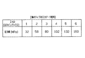
上記説明では噴射期間データ配列(図8)と振り分けマップ(図13)とを、他のタイプの燃料噴射弁の特性に対応して変更した例(図14,15,16,17)を示した。しかし、更に圧力データ配列(図7)についても燃料噴射弁の特性に対応して変更(例えば図18)することにより、2次元コード62a〜62dから得られる限られた数(ここでは12個)の噴射補正量でも各種の燃料噴射弁に対する高精度な燃料噴射量制御が可能となる。
【0122】
上述した構成において、図11の噴射補正量データ配列がマップ形成用データに、2次元コード62a〜62dが情報記録媒体に、図3〜6の噴射補正量マップがデータマップに、2次元コードリーダ60aを備えた書き込み装置60が媒体データ読み出し手段に、燃料噴射弁4a〜4dが機構に相当する。そして、図13の振り分けマップが振り分け情報に、この振り分けマップを記憶しているECU3内のROMが振り分け情報記憶手段に相当する。又、図12のROM書き込み処理がデータ振り分け手段としての処理に相当する。
【0123】
以上説明した本実施の形態1によれば、以下の効果が得られる。
(イ).ECU3内のROMに記憶されている振り分けマップ(図13)は、図3〜6の噴射補正量マップが適用される燃料噴射弁4a〜4dの種類に対応して設定されている。このため書き込み装置60が2次元コード62a〜62dから読み取った噴射補正量データを、ROM書き込み処理(図12)にてどのようにマップ上に振り分けるかは、燃料噴射弁の種類毎に自由に設定できる。
【0124】
このように燃料噴射弁の種類に対応した密度分布で噴射補正量データを配置した噴射補正量マップを作成できる。このため、2次元コード62a〜62dに記録できるデータ量が限られていても、前述した図7,8,13,14,15,16,17,18に示したごとく高い自由度で補正点を変更設定することができ、燃料噴射弁の種類別に高精度なデータマップが利用できるようになる。
【0125】
[実施の形態2]
本実施の形態は、前記実施の形態1の図10,11に示した2次元コード62a〜62dを作成する噴射補正量測定装置について示すものである。図19に噴射補正量測定装置の概略構成図を示す。
【0126】
本噴射補正量測定装置は、噴射量測定機70、測定制御装置72及び2次元コード印刷機74を備えている。噴射量測定機70は内部に燃料噴射弁4を配置することにより、内部に備えられた燃料加圧装置及び燃料噴射弁電磁弁駆動装置等により、所望の値に設定した燃料圧力と噴射期間とで燃料噴射弁4から燃料を噴射させて、その噴射量を測定できる装置である。
【0127】
測定制御装置72は、キー入力部72a、フロッピィデスクドライブ等のデータ読み取り部72b、表示部72cなどを備えて、マイクロコンピュータを中心として構成されているものである。この測定制御装置72は、キー入力、フロッピィデスクなどの情報記録媒体あるいはホストコンピュータからの測定制御情報により、噴射量測定機70における測定を制御して、燃料噴射弁4における噴射特性データを測定する。そしてこの測定結果に基づいて、測定制御装置72は、燃料補正量データを設定し、この燃料補正量データを配列情報に基づいて1次元の配列として2次元コード印刷機74により2次元コード62に印刷して出力させる。
【0128】
この測定制御装置72により実行される噴射補正量マップ作成用2次元コード作成処理を図20,21に示す。本処理はキー入力部72aからの開始指示入力により開始される処理である。
【0129】
本処理が開始されると、まず測定開始条件が成立しているか否かが判定される(S300)。例えば、噴射量測定機70側では燃料噴射弁4が正しく配置されている状態、燃料が存在する状態、加圧ポンプその他の機構が正常である状態が測定開始条件とされている。測定制御装置72側では、データ読み取り部72bあるいはホストコンピュータから測定用データが読み込まれている状態、あるいは読み込み可能な状態が測定開始条件とされている。この測定用データとしては、前記実施の形態1にて説明した圧力データ配列(図7)、噴射期間データ配列(図8)及び振り分けマップ(図13)の各データである。
【0130】
このような測定開始条件が1つでも満足されていないと(S300で「NO」)、測定を開始することができないので、表示部72cに測定不能の原因を示すエラー表示をして(S302)、このまま一旦本処理を終了する。
【0131】
測定開始条件が全て満足されていると(S300で「YES」)、次に圧力データ配列(図7)から新たな圧力値Psを噴射量測定機70側に設定する(S304)。ここでは最初であるので圧力データ配列(図7)の第1インデックスIxp=1の圧力値「32MPa」が噴射量測定機70側に設定される。このことにより噴射量測定機70側では、燃料噴射弁4に供給する燃料圧力を「32MPa」に調整する。
【0132】
次に噴射期間データ配列(図8)から圧力値「32MPa」(第1インデックスIxp=1)における新たな噴射期間Tsを噴射量測定機70側に設定する(S306)。ここでは第1インデックスIxp=1における最初の噴射期間の抽出であるので、第2インデックスIxt=1の噴射期間「540μs」が噴射量測定機70側に設定される。このことにより噴射量測定機70側では、燃料噴射弁4の開弁期間を噴射期間「540μs」として設定して、燃料噴射弁4から燃料噴射を実行する。そして実際に噴射された燃料量を測定して、測定制御装置72側に送信する。
【0133】
測定制御装置72側では、後述する噴射期間補正量dfに「0」を設定した(S307)後、測定結果の受信待ちとなる(S308)。測定結果が受信されると(S308で「YES」)、測定された噴射量が、予め設定されている標準燃料噴射弁による同一条件(圧力値「32MPa」、噴射期間「540μs」)での噴射量との間に差が無いか否かが判定される(S310)。この差が無いか否かの判定は、標準燃料噴射弁の噴射量に対して同一と認められる程度の範囲で近似していれば、差は無いと判定され、範囲から外れていれば差があると判定される。
【0134】
ここで差が存在する場合には(S310で「NO」)、この差を小さくする方向へ噴射期間Tsを補正するための噴射期間補正量dfの値を変更する(S312)。例えば、測定された噴射量が標準の噴射量よりも少なければ、噴射期間補正量dfを漸増し、測定された噴射量が標準の噴射量よりも多ければ、噴射期間補正量dfを漸減する処理が行われる。
【0135】
そして、噴射期間Tsと噴射期間補正量dfとを加えた期間を新たな噴射期間として噴射量測定機70側に設定する(S314)。このことにより噴射量測定機70側では、燃料噴射弁4の開弁期間を噴射期間「540μs+df」として設定して、燃料噴射弁4から燃料噴射を実行する。そして実際に噴射された燃料量を測定して、測定制御装置72側に送信する。
【0136】
測定制御装置72側では、測定結果の受信待ちに戻る(S308)。そして測定結果が受信されると(S308で「YES」)、測定された噴射量が、予め得られている標準燃料噴射弁による同一条件(圧力値「32MPa」、噴射期間「540μs」)での噴射量との間に差が無いか否かが判定される(S310)。
【0137】
ここでも差が存在する場合には(S310で「NO」)、再度ステップS312,S314を実行して、標準噴射量に近づくように変更した噴射期間を噴射量測定機70側に設定して、測定結果の受信を待つ(S308)。
【0138】
このような噴射期間の変更設定処理が、実際の噴射量が標準噴射量との差が無くなるまで実行される。そして実際の噴射量と標準噴射量との差が無くなると(S310で「YES」)、振り分けマップ(図13)を配列情報として用いて噴射期間補正量dfを測定制御装置72のメモリ上に記憶する(S316)。すなわち、今回の第1インデックスIxp=1、第2インデックスIxt=1におけるマップ上の数値は、振り分けマップ(図13)上で「1」であるので、これをインデックスとして測定制御装置72のメモリ上に記憶する。
【0139】
次に、噴射期間データ配列(図8)を参照して同一圧力値において次の第2インデックスIxtに新たな噴射期間が無いか否かが判定される(S318)。「32MPa」(第1インデックスIxp=1)においては、第2インデックスIxt=2は「1580μs」で新たな噴射期間であることから(S318で「NO」)、「1580μs」を新たな噴射期間Tsとして噴射量測定機70側に設定する(S306)。
【0140】
そして噴射期間補正量dfに「0」を設定した(S307)後、測定結果の受信待ちとなる(S308)。測定結果が受信されると(S308で「YES」)、測定された噴射量が、予め得られている標準燃料噴射弁による同一条件(圧力値「32MPa」、噴射期間「1580μs」)での噴射量とに差が無いか否かが判定される(S310)。差が有れば(S310で「NO」)、前述したごとく、噴射期間補正量dfの値を変化させることによる測定が、実際の噴射量と標準噴射量との差が無くなるまで実行される(S312,S314)。
【0141】
そして実際の噴射量と標準噴射量との差が無くなれば(S310で「YES」)、振り分けマップ(図13)を配列情報として用いて噴射期間補正量dfを測定制御装置72のメモリ上に記憶する(S316)。すなわち、今回の第1インデックスIxp=1、第2インデックスIxt=2における振り分けマップ(図13)上の数値は「2」であるので、これをインデックスとして測定制御装置72のメモリ上に記憶する。
【0142】
次に、噴射期間データ配列(図8)を参照して同一圧力値において次の第2インデックスIxtに新たな噴射期間が無いか否かが判定される(S318)。「32MPa」(第1インデックスIxp=1)においては、次の第2インデックスIxt=3は「1580μs」で、第2インデックスIxt=2と同じである。したがって新たな噴射期間は無いことから(S318で「YES」)、次に圧力データ配列(図7)を参照して新たな圧力値が無いか否かが判定される(S320)。次の第1インデックスIxp=2は「64MPa」であり、新たな圧力値であるので(S320で「NO」)、新たな圧力値Psとして「64MPa」を噴射量測定機70側に設定する(S304)。
【0143】
そして「64MPa」(第1インデックスIxp=2)においては、第2インデックスIxt=1の「480μs」は新たな噴射期間であることから、「480μs」を新たな噴射期間Tsとして噴射量測定機70側に設定する(S306)。
【0144】
そして噴射期間補正量dfに「0」を設定した(S307)後、測定結果の受信待ちとなる(S308)。測定結果が受信されると(S308で「YES」)、測定された噴射量が、予め得られている標準燃料噴射弁による同一条件(圧力値「64MPa」、噴射期間「480μs」)での噴射量との間に差が無いか否かが判定される(S310)。差が有れば(S310で「NO」)、前述したごとく、噴射期間補正量dfの値を変化させることによる測定が、実際の噴射量と標準噴射量との差が無くなるまで実行される(S312,S314)。
【0145】
そして実際の噴射量と標準噴射量との差が無くなれば(S310で「YES」)、振り分けマップ(図13)を配列情報として用いて噴射期間補正量dfを測定制御装置72のメモリ上に記憶する(S316)。すなわち、今回の第1インデックスIxp=2、第2インデックスIxt=1における振り分けマップ(図13)上の数値は「3」であるので、これをインデックスとして測定制御装置72のメモリ上に記憶する。
【0146】
このようにして、順次、第1インデックスIxp=2については、第2インデックスIxt=1〜3にて、噴射量の測定が実行されて、標準噴射量と差が無くなる噴射期間補正量dfの値が、振り分けマップ(図13)上のインデックス「3,4,5」により、測定制御装置72のメモリ上に記憶される。
【0147】
更に、第1インデックスIxp=3については第2インデックスIxt=1〜3にて噴射量の測定が実行されて、標準噴射量と差が無くなる噴射期間補正量dfの値が、振り分けマップ(図13)上のインデックス「6,7,8」により、測定制御装置72のメモリ上に記憶される。
【0148】
更に、第1インデックスIxp=4については第2インデックスIxt=1,2にて噴射量の測定が実行されて、標準噴射量と差が無くなる噴射期間補正量dfの値が、振り分けマップ(図13)上のインデックス「9,10」により、測定制御装置72のメモリ上に記憶される。
【0149】
更に、第1インデックスIxp=5については第2インデックスIxt=1,2にて噴射量の測定が実行されて、標準噴射量と差が無くなる噴射期間補正量dfの値が、振り分けマップ(図13)上のインデックス「11,12」により、測定制御装置72のメモリ上に記憶される。
【0150】
そして第1インデックスIxp=5、第2インデックスIxt=2での噴射期間補正量dfの記憶処理(S316)が終了すると、次に噴射期間データ配列(図8)を参照して同一圧力値において次の第2インデックスIxtに新たな噴射期間が無いか否かが判定される(S318)。第2インデックスIxt=3における噴射期間「650μs」は第2インデックスIxt=2と同じであるので、新たな噴射期間が無い(S318で「YES」)と判定される。
【0151】
次に圧力データ配列(図7)を参照して新たな圧力値が無いか否かが判定される(S320)。次の第1インデックスIxp=6の圧力値は「160MPa」であり、第1インデックスIxp=5と同じである。したがって新たな圧力値は無いと判定される(S320「YES」)。
【0152】
そして次に、上述したごとく振り分けマップ(図13)から得られたインデックス「1〜12」によりメモリ上に記憶されている12個の噴射期間補正量dfの値が、燃料噴射弁4の機種データと共に2次元コード化されて、2次元コード印刷機74に印刷データとして送信される(S322)。このことにより2次元コード印刷機74から2次元コード62として印刷出力される。
【0153】
こうして噴射補正量マップ作成用2次元コード作成処理(図20,21)を終了する。そして、作業者が測定済みの燃料噴射弁4を噴射量測定機70から取り出して、2次元コード印刷機74から出力された2次元コード62を貼り付ける。そしてこのような処理を繰り返して、個々の燃料噴射弁4に対して噴射量のばらつきを表す2次元コード62が作成されて、該当する燃料噴射弁4に取り付けられる。
【0154】
このことにより、前記実施の形態1の図11に示すごとくの噴射補正量配列データが2次元コード62に形成される。したがって、この2次元コード62が取り付けられた燃料噴射弁4を、前記実施の形態1の図10〜図13にて説明したごとく、ディーゼルエンジンに組み付ける際に、2次元コード62から読み取って、振り分けマップ(図13)によりエンジン制御用ECU内のメモリに振り分ける。このことにより、エンジン制御用ECU内に、個々の燃料噴射弁4の噴射量のばらつきに対応した噴射補正量マップ(図3〜6)が完成する。
【0155】
上述した構成において、図3〜6の噴射補正量マップがデータマップに、2次元コードが情報記録媒体に、噴射期間補正量dfがマップ形成用データに、図7の圧力データ配列及び図8の噴射期間データ配列が測定点情報に相当する。そして、図7,8のデータ配列を記憶している測定制御装置72内のメモリが測定点情報記憶手段に、噴射量測定機70が測定手段に、図13の振り分けマップが配列情報に、図13の振り分けマップを記憶している測定制御装置72内のメモリが配列情報記憶手段に相当する。更に、噴射補正量マップ作成用2次元コード作成処理(図20,21)の処理が、測定手段、マップ形成用データ設定手段、及びマップ形成用データ記録手段としての処理に相当する。
【0156】
以上説明した本実施の形態2によれば、以下の効果が得られる。
(イ).図7の圧力データ配列及び図8の噴射期間データ配列は図3〜6の噴射補正量マップが適用される燃料噴射弁4の種類に対応して設定されている。このため燃料噴射弁4の種類毎に自由に測定点を設定できるので、本噴射補正量測定装置は、形成すべき噴射補正量マップにおいて高密度にデータが必要な領域と低密度でも良い領域とが燃料噴射弁4の種類毎に異なっていても、少ない測定点での測定で対応することができる。具体的には12点にて各種の燃料噴射弁の噴射量のばらつきに高精度に対応した噴射補正量マップを実現することができる。
【0157】
このため本噴射補正量測定装置は、燃料噴射弁4に対する測定により求める噴射期間補正量dfは少ない数を求めるのみで済むので、効率的に測定ができる。更に2次元コード62には少ないデータ量を、図13の振り分けマップの配列情報に従って記録するだけで済む。そして、このように記録された2次元コード62を、例えば、前記実施の形態1にて用いることにより、少ないデータ量で、燃料噴射弁4の種類に対応した密度分布でデータを配置した噴射補正量マップが作成でき、燃料噴射弁4の種類別に高精度な噴射補正量マップが利用できるようになる。
【0158】
[実施の形態3]
本実施の形態では、前記実施の形態1,2に用いた噴射期間データ配列(図8)及び振り分けマップ(図13)を作成する補正点データ作成処理について説明する。尚、この補正点データ作成処理は、前記実施の形態2の図19にて示したシステム構成を用いて、測定制御装置72において機能するプログラムを変更することにより実行される。
【0159】
又、この補正点データ作成処理にて用いるために、実際の燃料噴射弁4が用いられる燃料圧力範囲を等分割することにより予め圧力データ配列(図7)を設定しておく。更に、図7の各圧力値に対して、図22に示すごとくの噴射期間データ配列(μs)を設定しておく。この図22の噴射期間データ配列(μs)は各圧力値での補正候補点となる噴射期間を表し、各圧力値において実際に噴射が行われる噴射期間の範囲全体に分布した補正候補点を設定したものである。ここでは各噴射期間範囲に下限噴射期間から上限噴射期間までに10点の補正候補点が設定してある。
【0160】
測定制御装置72が実行する補正点データ作成処理を図23,24に示す。
本処理が開始されると、まず測定開始条件が成立しているか否かが判定される(S400)。例えば、噴射量測定機70側では燃料噴射弁4が正しく配置されている状態、燃料が存在する状態、加圧ポンプその他の機構が正常である状態が測定開始条件とされている。測定制御装置72側では、データ読み取り部72bあるいはホストコンピュータから測定用データが読み込まれている状態、あるいは読み込み可能な状態が測定開始条件とされている。この測定用データとしては、前記実施の形態1にて説明した圧力データ配列(図7)及びこの圧力データ配列の各圧力値での噴射期間を示す図22に示すごとくの補正候補点用噴射期間データ配列の各データである。
【0161】
このような測定開始条件が1つでも満足されていないと(S400で「NO」)、測定を開始することができないので、表示部72cに測定不能の原因を示すエラー表示をして(S402)、このまま一旦本処理を終了する。
【0162】
測定開始条件が全て満足されると(S400で「YES」)、次に圧力データ配列(図7)から新たな圧力値Pを噴射量測定機70側に設定する(S404)。ここでは最初であるので圧力データ配列(図7)の第1インデックスIxp=1の圧力値「32MPa」が噴射量測定機70側に設定される。このことにより噴射量測定機70側では、燃料噴射弁4に供給する燃料圧力を「32MPa」に調整する。
【0163】
次に補正候補点用噴射期間データ配列(図22)から圧力値「32MPa」(第1インデックスIxp=1)における新たな噴射期間Tを噴射量測定機70側に設定する(S406)。ここでは第1インデックスIxp=1における最初の噴射期間の抽出であるので、噴射期間候補インデックスKt=1の噴射期間「540μs」が噴射量測定機70側に設定される。このことにより噴射量測定機70側では、燃料噴射弁4の開弁期間を噴射期間「540μs」として設定して、燃料噴射弁4から燃料噴射を実行する。そして実際に噴射された燃料量を測定して、測定制御装置72側に送信する。
【0164】
測定制御装置72側では、噴射期間補正量dfに「0」を設定した(S407)後、測定結果の受信待ちとなる(S408)。測定結果が受信されると(S408で「YES」)、測定された噴射量が、予め設定されている標準燃料噴射弁による同一条件(圧力値「32MPa」、噴射期間「540μs」)での噴射量との間に差が無いか否かが判定される(S410)。この差が無いか否かの判定については、前記図21のステップS310にて説明したごとくである。
【0165】
ここで差が存在する場合には(S410で「NO」)、この差を小さくする方向へ噴射期間Tを補正するための噴射期間補正量dfの値を変更する(S412)。この噴射期間補正量dfの変更は前記図21のステップS312にて述べたごとくの漸増漸減がおこなわれる。
【0166】
そして、噴射期間Tと噴射期間補正量dfとを加えた期間を新たな噴射期間として噴射量測定機70側に設定する(S414)。このことにより噴射量測定機70側では、燃料噴射弁4の開弁期間を噴射期間「540μs+df」として設定して、燃料噴射弁4から燃料噴射を実行する。そして実際に噴射された燃料量を測定して、測定制御装置72側に送信する。
【0167】
測定制御装置72側では、測定結果の受信待ちに戻る(S408)。そして測定結果が受信されると(S408で「YES」)、測定された噴射量が、予め得られている標準燃料噴射弁による同一条件(圧力値「32MPa」、噴射期間「540μs」)での噴射量との間に差が無いか否かが判定される(S410)。
【0168】
ここでも差が存在する場合には(S410で「NO」)、再度ステップS412,S414を実行して、標準噴射量に近づくように変更した噴射期間を噴射量測定機70側に設定して、測定結果の受信を待つ(S408)。
【0169】
このような噴射期間の変更設定処理が、実際の噴射量と標準噴射量との差が無くなるまで実行される。そして、実際の噴射量と標準噴射量との差が無くなると(S410で「YES」)、第1インデックスIxpと噴射期間候補インデックスKtとに基づいて測定制御装置72のメモリ上に配列して噴射期間補正量dfを保存する(S416)。
【0170】
次に、補正候補点用噴射期間データ配列(図22)を参照して同一圧力値において次の噴射期間候補インデックスKtに新たな噴射期間が無いか否かが判定される(S418)。「32MPa」(第1インデックスIxp=1)においては、噴射期間候補インデックスKt=2に「660μs」が存在することから(S418で「NO」)、「660μs」を新たな噴射期間Tとして噴射量測定機70側に設定する(S406)。
【0171】
そして噴射期間補正量dfに「0」を設定した(S407)後、測定結果の受信待ちとなる(S408)。測定結果が受信されると(S408で「YES」)、測定された噴射量が、予め得られている標準燃料噴射弁による同一条件(圧力値「32MPa」、噴射期間「660μs」)での噴射量との間に差が無いか否かが判定される(S410)。差が有れば(S410で「NO」)、前述したごとく、噴射期間補正量dfの値を変化させることによる測定が、実際の噴射量と標準噴射量との差が無くなるまで実行される(S412,S414)。
【0172】
そして実際の噴射量と標準噴射量との差が無くなれば(S410で「YES」)、第1インデックスIxpと噴射期間候補インデックスKtとに基づいて測定制御装置72のメモリ上に噴射期間補正量dfを配列して保存する(S416)。
【0173】
次に、補正候補点用噴射期間データ配列(図22)を参照して同一第1インデックスIxpにおいて次の噴射期間候補インデックスKtに新たな噴射期間が無いか否かが判定される(S418)。第1インデックスIxp=1においては、次の噴射期間候補インデックスKt=3の「780μs」が存在することから(S418で「NO」)、「780μs」を新たな噴射期間Tとして噴射量測定機70側に設定する(S406)。そして前述したごとくステップS407〜S416を実行して、実際の噴射量と標準噴射量との差が無くなった時の噴射期間補正量dfを保存する。
【0174】
以後、第1インデックスIxp=1において新たな噴射期間が存在する限り、ステップS407〜S416を実行する。このことで、「890μs」、「1010μs」、「1120μs」、「1240μs」、「1350μs」、「1470μs」、「1580μs」にて、実際の噴射量と標準噴射量との差が無くなった時の噴射期間補正量dfをそれぞれ保存する。
【0175】
そして、第1インデックスIxp=1にて噴射期間候補インデックスKt=10の「1580μs」における噴射期間補正量dfを保存した後は、第1インデックスIxp=1において次の噴射期間候補インデックスKtに新たな噴射期間が無くなる(S418で「YES」)。したがって次に新たな圧力値が無いか否かが判定される(S420)。次の第1インデックスIxp=2に新たな圧力値「64MPa」が存在するので(S420で「NO」)、この圧力値「64MPa」が新たな圧力値Pとして噴射量測定機70側に設定される(S404)。
【0176】
そして「64MPa」(第1インデックスIxp=2)においては、噴射期間候補インデックスKt=1の「480μs」は新たな噴射期間であることから、「480μs」を新たな噴射期間Tとして噴射量測定機70側に設定する(S406)。
【0177】
そして前述したステップS407〜S414の処理により得られた噴射期間補正量dfを測定制御装置72のメモリ上に保存する(S416)。そして以下、第1インデックスIxp=2における噴射期間候補インデックスKt=2〜10についてもステップS407〜S416の処理により噴射期間補正量dfをそれぞれ保存する。
【0178】
同様にして第1インデックスIxp=3〜5における噴射期間候補インデックスKt=1〜10についてもステップS407〜S416の処理により噴射期間補正量dfをそれぞれ保存する。
【0179】
このようにして、50個の噴射期間補正量dfの値が算出されて保存される。
そして第1インデックスIxp=5の噴射期間候補インデックスKt=10における噴射期間補正量dfの算出と保存とが終了すると、新たな噴射期間も新たな圧力値も存在しないので(S418で「YES」、S420で「YES」)、次に必要サンプル数が完了したか否かが判定される(S422)。例えば、測定サンプルとして8個の燃料噴射弁4を用いるように測定制御装置72に予め設定していれば、8個終了していなければ(S422で「NO」)、新たな燃料噴射弁4に対しての測定要求が表示部72cになされる(S424)。こうして一旦本処理を終了する。
【0180】
以後、新たな燃料噴射弁4を噴射量測定機70に配置して測定開始条件が成立すると(S400で「YES」)、新たな燃料噴射弁4について上述したごとく圧力データ配列(図7)と補正候補点用噴射期間データ配列(図22)とを用いて噴射量が測定される。このことにより新たに50個の噴射期間補正量dfが保存される。このようにして8個の燃料噴射弁4について、第1インデックスIxp=1〜5、噴射期間候補インデックスKt=1〜10の配列に対する各50個の噴射期間補正量dfが得られる。
【0181】
次にこのようにして必要サンプル数が完了すると(S422で「YES」)、得られた噴射期間補正量dfを用いて補正点設定処理が実行される(S500)。補正点設定処理を図25に示す。本処理では、まず50点存在する補正候補点での各8個の噴射期間補正量dfの平均値dfaveを算出する(S502)。
【0182】
そして各圧力値において10点存在する補正候補点の減数化を実行する(S504)。すなわち、噴射補正量マップを作成するために、不要な補正候補点を削除する処理を行う。この減数化処理の一例としては最小二乗法により中間の補正候補点を削除する方法が挙げられる。
【0183】
例えば、図26(A)に示すごとく、10個の補正候補点の噴射期間T1〜T10において、噴射期間補正量平均値dfaveに対する最小二乗法により直線L1を求めた場合を考える。この時、各補正候補点における噴射期間補正量平均値dfaveと直線L1との誤差が、許容範囲に入っている場合には、10個の補正候補点の内の2点、ここでは両端の噴射期間T1,T10の補正候補点を残して、他の8個の補正候補点を候補から除外する。
【0184】
又、1本の直線では誤差が許容範囲に入らない場合には、図26(B)に示すごとく、或る補正候補点(図では噴射期間T4)で2つに分割して最小二乗法により直線L1,L2を求める。この時に、各補正候補点における噴射期間補正量平均値dfaveと直線L1,L2との誤差が許容範囲に入っている場合には、10個の補正候補点の内の両端の2点(噴射期間T1,T10)と境界となる補正候補点(噴射期間T4)の補正候補点を残して、他の7個の補正候補点を候補から除外する。
【0185】
又、2本の直線では誤差が許容範囲に入らない場合には、図26(C)に示すごとく、或る2つの補正候補点(図では噴射期間T4,T7)で3つに分割して最小二乗法により直線L1,L2,L3を求める。この時に、各補正候補点における噴射期間補正量平均値dfaveと直線L1,L2,L3との誤差が許容範囲に入っている場合には、10個の補正候補点の内の両端の2点(噴射期間T1,T10)と境界となる補正候補点(噴射期間T4,T7)の補正候補点を残して、他の6個の補正候補点を候補から除外する。
【0186】
又、図26(A)に示したごとく10個の補正候補点の噴射期間T1〜T10において最小二乗法により直線L1を求めると、各補正候補点における噴射期間補正量平均値dfaveと直線L1との誤差が許容範囲に入っている場合には、更に次の処理を行う。すなわち、図26(D)に示すごとく直線L1を噴射期間T軸に平行にしても、各補正候補点における噴射期間補正量平均値dfaveと直線L1との誤差が許容範囲に入る場合には、10個の補正候補点の内の1点、例えば最長の噴射期間T10の補正候補点を残して、他の9個の補正候補点を候補から除外する。
【0187】
上述したごとくの減数化処理(S504)が第1インデックスIxp=1〜5についてそれぞれ終了すると、次に候補として残った補正候補点数が12以下か否かが判定される(S506)。残った補正候補点数が12以下であれば(S506で「YES」)、この補正候補点を補正点として決定して、噴射期間データ配列と振り分けマップとの作成が行われる(S508)。
【0188】
例えば、第1インデックスIxp=1において噴射期間候補インデックスKt=1,10が、第1インデックスIxp=2において噴射期間候補インデックスKt=1,4,10が、第1インデックスIxp=3において噴射期間候補インデックスKt=1,4,10が、第1インデックスIxp=4において噴射期間候補インデックスKt=1,10が、第1インデックスIxp=5において噴射期間候補インデックスKt=1,10が、補正候補点として残っていれば、前記実施の形態1の図8に示した噴射期間データ配列(図8のハッチング以外の部分)が作成される。
【0189】
尚、図8において第1インデックスIxp=1〜5のハッチングの部分は、データがなくて使用されない領域であることを示すために単に配列の左に隣接する値を入れた領域を示している。又、第1インデックスIxp=6については測定自体実行していないので、使用されない領域であることを示すために第1インデックスIxp=5の配列をそのまま入れている。
【0190】
そしてこの噴射期間データ配列に、第1インデックスIxp=1、噴射期間候補インデックスKt=1から、順に番号を付すことで、前記実施の形態1の図13に示した振り分けマップが作成される。尚、図13においてハッチング部分は図8にて説明した場合と同じである。こうして本処理を終了する。
【0191】
又、補正候補点数が12を越えている場合には(S506で「NO」)、減数化条件を強化して、再度、各圧力値での補正候補点の減数化処理(S504)を実行する。減数化条件の強化とは、例えば、噴射期間補正量平均値dfaveと最小二乗法により得られる直線との誤差に対する許容範囲を大きくすることにより、残される補正候補点を少なくすることができる。こうして残される補正候補点数が12以下となれば、この補正候補点を補正点として決定して、噴射期間データ配列と振り分けマップとの作成が行われる(S508)。こうして本処理を終了する。
【0192】
尚、図8,図13は残された補正候補点数が12点の場合を例示したが、燃料噴射弁の種類によっては、10点となることもあり、4点となることもある。
上述した構成において、圧力データ配列(図7)と補正候補点用噴射期間データ配列(図22)とで表される測定点が標準測定点に、噴射期間補正量平均値dfaveが測定値と標準値との偏差に相当する。又、噴射量測定機70による噴射量の測定が、噴射状態の測定に相当する。
【0193】
以上説明した本実施の形態3によれば、以下の効果が得られる。
(イ).上述のごとく燃料噴射弁の種類別に形成された噴射期間データ配列(図8)及び振り分けマップ(図13)を前記実施の形態2に用いることにより、燃料噴射弁の種類に対応させて燃料噴射補正量の密度分布を任意に変更した燃料噴射補正量マップを作成できる2次元コードを作成することができる。
【0194】
そしてこのように作成された2次元コードを前記実施の形態1に用いることによって、12点以下の少ない燃料噴射補正量データにても燃料噴射弁の種類別に高精度な燃料噴射補正量マップが作成できようになる。
【0195】
[実施の形態4]
本実施の形態では、前記実施の形態3とは異なり、予め補正点数が振り分けマップとして設定されている状態で、前記実施の形態1,2に用いた噴射期間データ配列(図8)を作成する。このため前記実施の形態3の補正点設定処理(図25)の代わりに、図27に示す補正点設定処理が実行される。
【0196】
補正点設定処理(図27)について説明する。まず図25のステップS502にて述べたごとく、50点存在する各補正候補点での噴射期間補正量平均値dfaveを算出する(S602)。
【0197】
次に予め設定されている振り分けマップに応じて補正候補点数を減数化して補正点を設定する(S604)。例えば、前記補正点データ作成処理(図23,24)にて既に測定された8個の燃料噴射弁4のデータに基づいて作業者により前述した図15に示すごとくの振り分けマップが作成されているとする。この図15の振り分けマップでは、第1インデックスIxp=1では、4点の補正点が設定されることになる。例えば、補正候補点である噴射期間T1〜T10の両端の噴射期間T1,T10を除いた中間の2点を順次選択することで、3つの領域に補正候補点を分割する。そして、それぞれの領域において前記実施の形態3にて述べたごとく最小二乗法を実行し、二乗誤差の合計が最も小さくなる中間の2点を選択する。そして両端の噴射期間T1,T10と選択した中間の2点との4点を、第1インデックスIxp=1での補正点として設定する。
【0198】
第1インデックスIxp=2では3点の補正点が設定されることになるので、両端の噴射期間T1,T10を除いた中間の1点を順次選択することで、2つの領域に補正候補点を分割する。そして、それぞれの領域において前述したごとく最小二乗法により二乗誤差の合計が最も小さくなる中間の1点を選択する。そして、両端の噴射期間T1,T10と選択した中間の1点との3点を補正点として設定する。
【0199】
第1インデックスIxp=3,4では2点の補正点が設定されることになるので、両端の噴射期間T1,T10を補正点とする。
第1インデックスIxp=5では1点の補正点が設定されることになるので、両端の噴射期間T1,T10の一方、例えば噴射期間T10を補正点とする。あるいは噴射期間T1〜T10の内、最小二乗法により得られた直線に最も近い補正候補点を補正点とする。
【0200】
このようにして各圧力値において補正点が決定されると、該当する補正点の噴射期間が抽出されて振り分けマップに応じて配列されることにより、例えば図14に示したごとくの噴射期間データ配列が作成される(S606)。
【0201】
以上説明した本実施の形態4によれば、以下の効果が得られる。
(イ).上述のごとく燃料噴射弁の種類別に形成された噴射期間データ配列及び予め設定された振り分けマップを前記実施の形態2に用いることにより、燃料噴射弁の種類に対応させて燃料噴射補正量の密度分布を任意に変更した燃料噴射補正量マップを作成できる2次元コードを作成することができる。
【0202】
そしてこのように作成された2次元コードを前記実施の形態1に用いることによって、12点以下の少ない燃料噴射補正量データにても燃料噴射弁の種類別に高精度な燃料噴射補正量マップが作成できようになる。
【0203】
尚、作業者により振り分けマップの作成時に、適用されるディーゼルエンジン自体の性能要求を加味して、振り分けマップによる補正点の密度を変更することができる。このため、12点以下の少ない燃料噴射補正量データでも、燃料噴射弁の特性と共に、更に他の要求も加味した高精度な燃料噴射補正量マップが作成でき、かつ利用できるようになる。
【0204】
[その他の実施の形態]
(a).情報記録媒体としては、2次元コードに限らず、バーコードなどを用いても良い。又、多数のデータを記録できる情報記録媒体を用いても良い。いずれにしても、データ量は少なくて済むので、情報記録媒体へ記録する噴射補正量データ作成のための測定処理が迅速に行われ、情報記録媒体から読み出した噴射補正量データにより作成される噴射補正量マップも小さいものとなり、メモリが小さくて済む。
【0205】
(b).前記実施の形態1の噴射補正量マップにおける補間計算では、直線の補間計算を実行していたが、これとともに補正点間に重み付けを加えた補間計算でも良い。
【0206】
(c).前記実施の形態1,2では、前記実施の形態3,4によらずに、作業者が実験的に求めて適切な補正点を設定し、これから作業者が作成した圧力データ配列(例えば図7)、噴射期間データ配列(例えば図8)及び振り分けマップ(例えば図13)を用いても良い。そして、この場合において、適用されるディーゼルエンジン自体の性能要求を加味して、振り分けマップによる補正点の密度を変更することができる。このため、12点以下の少ない燃料噴射補正量データでも、燃料噴射弁の特性と共に、更に他の要求も加味した高精度な燃料噴射補正量マップが作成でき、かつ利用できるようになる。
【0207】
(d).前記実施の形態4では、各圧力値において予め補正点数を決定していたが、一部の圧力値のみについて予め補正点数を決定しておき、他の圧力値においては、前記実施の形態3のごとくの装置により補正点数自体を算出して求めても良い。この場合も補正点が12点以内にとならない場合には、減数化条件を強化して補正候補点の減数化を繰り返す。
【0208】
(e).前記各実施の形態では、ディーゼルエンジンの燃料噴射弁の噴射特性を表す噴射補正量マップの作成に関するものであったが、筒内燃料噴射や吸気ポート燃料噴射などのガソリンエンジンの燃料噴射弁の噴射特性を表す噴射補正量マップの作成にも適用できる。又、ディーゼルエンジンにおいてもコモンレール型ばかりでなく、他のタイプの噴射システムにおいても各気筒における噴射特性を表す噴射補正量マップの作成にも適用できる。
【0209】
又、燃料噴射弁以外の装置についても適用できる。例えば、EGR弁などの開度制御、スロットルバルブの開度制御、あるいは各種センサによる測定などにおいて、開度補正量マップ、測定出力補正量マップの作成に適用できる。
【0210】
(f).図2の燃料噴射量制御処理では、パイロット噴射とメイン噴射とを実行するディーゼルエンジンに対する処理であったが、メイン噴射のみを実行する場合にも適用できる。又、メイン噴射の後に、膨張行程又は排気行程において噴射するアフター噴射を実行する場合にも、アフター噴射の噴射期間の補正に関しても、前述したパイロット噴射やメイン噴射と同様に、図3〜6の噴射補正量マップが適用される。
【図面の簡単な説明】
【図1】実施の形態1の蓄圧式ディーゼルエンジンとその制御系統を示す概略構成図。
【図2】実施の形態1のECUが実行する燃料噴射量制御処理のフローチャート。
【図3】上記燃料噴射量制御処理にて用いられる#1気筒の噴射補正量マップの構成説明図。
【図4】同じく#2気筒の噴射補正量マップの構成説明図。
【図5】同じく#3気筒の噴射補正量マップの構成説明図。
【図6】同じく#4気筒の噴射補正量マップの構成説明図。
【図7】上記各噴射補正量マップのインデックスとの対応を示す圧力データ配列の構成説明図。
【図8】上記各噴射補正量マップのインデックスとの対応を示す噴射期間データ配列の構成説明図。
【図9】上記各噴射補正量マップによる補間計算の説明図。
【図10】実施の形態1の噴射補正量マップ作成システムの概略構成図。
【図11】実施の形態1の2次元コードにおけるデータ配列の構成説明図。
【図12】実施の形態1のECUが実行するROM書き込み処理のフローチャート。
【図13】上記ROM書き込み処理にて用いられる振り分けマップの構成説明図。
【図14】他のタイプの燃料噴射弁に対して用いられる噴射補正量マップのインデックスとの対応を示す噴射期間データ配列の構成説明図。
【図15】他のタイプの燃料噴射弁に対して用いられる振り分けマップの構成説明図。
【図16】他のタイプの燃料噴射弁に対して用いられる噴射補正量マップのインデックスとの対応を示す噴射期間データ配列の構成説明図。
【図17】他のタイプの燃料噴射弁に対して用いられる振り分けマップの構成説明図。
【図18】他のタイプの燃料噴射弁に対して用いられる噴射補正量マップのインデックスとの対応を示す圧力データ配列の説明図。
【図19】実施の形態2の噴射補正量測定装置の概略構成図。
【図20】実施の形態2の測定制御装置により実行される噴射補正量マップ作成用2次元コード作成処理のフローチャート。
【図21】同じく噴射補正量マップ作成用2次元コード作成処理のフローチャート。
【図22】実施の形態3にて用いられる補正候補点用噴射期間データ配列の構成説明図。
【図23】実施の形態3の測定制御装置により実行される補正点データ作成処理のフローチャート。
【図24】同じく補正点データ作成処理のフローチャート。
【図25】同じく補正点設定処理のフローチャート。
【図26】同じく補正候補点の減数化処理の説明図。
【図27】実施の形態4の測定制御装置により実行される補正点設定処理のフローチャート。
【符号の説明】
2…蓄圧式ディーゼルエンジン、3…ECU、4a〜4d…燃料噴射弁、5…電磁弁、6…コモンレール、8…供給配管、8a…逆止弁、10…サプライポンプ、10a…吐出ポート、10b…吸入ポート、10c…圧力制御弁、10d…リターンポート、12…燃料タンク、14…フィルタ、16…リターン配管、18…吸気通路、18a…吸気弁、20…排気通路、20a…排気弁、22…グロープラグ、22a…グローリレー、24…アクセルペダル、26…アクセルセンサ、30…スタータ、30a…スタータスイッチ、32…水温センサ、34…油温センサ、36…燃温センサ、38…燃圧センサ、40…NEセンサ、42…気筒判別センサ、44…トランスミッション、46…シフトポジションセンサ、48…車速センサ、50…エアコンスイッチ、60…書き込み装置、60a…2次元コードリーダ、62a,62b,62c,62d…2次元コード、70…噴射量測定機、72…測定制御装置、72a…キー入力部、72b…データ読み取り部、72c…表示部、74…2次元コード印刷機。[0001]
BACKGROUND OF THE INVENTION
The present invention relates to a data map creation method, a data map creation information recording medium creation method, and apparatuses thereof.
[0002]
[Prior art]
For example, in a fuel injection valve of a diesel engine, in order to correct variations in the injection amount, for each fuel injection valve, a plurality of injection periods necessary for a target injection amount with respect to several fuel pressure values in advance are set. The deviation of the injection period from the standard fuel injection valve is obtained as a correction value. This correction value is, for example, two-dimensionally encoded and attached to each fuel injection valve, and transferred to a diesel engine assembly department.
[0003]
In the assembly department, when the fuel injection valve is attached to each cylinder, the contents of the two-dimensional code attached to the fuel injection valve are read, and the obtained correction value is configured as a map using the fuel pressure and the injection period as parameters. Thus, it is stored in a memory in an ECU (electronic control unit) and used for controlling the fuel injection amount of each fuel injection valve.
[0004]
[Problems to be solved by the invention]
However, the performance requirements for the fuel injection valve differ depending on the type of diesel engine to be assembled, and there are various types of fuel injection valves with different characteristics according to such a requirement. Due to the difference in characteristics, in the map composed of the correction values, an area where high-precision control can be performed even with low-density correction points, and a control deviation becomes large unless correction points are provided at high density. The region where accurate control cannot be performed may vary depending on the type of fuel injection valve.
[0005]
Considering the case where the area where the correction points may be low density and the area where the correction points need to be high differ depending on the type of the fuel injection valve, the correction point has a high density with respect to the entire space between the fuel pressure and the injection period. It is necessary to arrange correction points.
[0006]
However, an information recording medium such as a two-dimensional code that can be attached to the fuel injection valve has a limited amount of information that can be recorded, and a large number of correction points corresponding to high-density correction points so as to be compatible with all types of fuel injection valves. Cannot be stored.
[0007]
Moreover, even if an information recording medium capable of storing a large number of correction values can be used, it is necessary to measure a large number of data in advance to obtain correction values. And when this many correction value is memorize | stored in an information recording medium and also a fuel injection valve is integrated in a diesel engine, it is necessary to read many correction values from an information recording medium, and to memorize | store it in the memory of ECU. For this reason, there is a risk of increasing the cost in terms of work and equipment.
[0008]
This is not limited to the fuel injection valve of the diesel engine, but is the same in the operation management of other mechanisms such as correction of detection values of the fuel injection valves of other engines and various sensors.
[0009]
An object of the present invention is to make it possible to use a highly accurate data map for each type of mechanism even with a small amount of data.
[0010]
[Means for Solving the Problems]
In the following, means for achieving the above object and its effects are described.
The data map creation method according to
[0012]
Therefore, a map in which data is arranged with a density distribution corresponding to the type of mechanism can be created even with a small amount of data, and a highly accurate data map can be used for each type of mechanism.
[0020]
Claim2In the data map creation method described in
An information recording medium such as a two-dimensional code has a limited amount of information that can be recorded, and can store a large number of correction values corresponding to high-density correction points so as to be compatible with all types of fuel injection valves. Can not. However, by configuring as in any one of
[0021]
An information recording medium creating method for creating a data map according to
[0030]
Claim4In the method for creating an information recording medium for creating a data map described in
[0031]
An information recording medium such as a two-dimensional code has a limited amount of information that can be recorded, and can store a large number of correction values corresponding to high-density correction points so as to be compatible with all types of fuel injection valves. Can not. But claims3If the data is obtained using the measurement point information as described in the above, even a data amount that can be recorded in a two-dimensional code can create a map in which data is arranged with a density distribution corresponding to the type of mechanism, A high-precision data map can be used for each type of mechanism.
[0036]
Claim5The data map creation device described inAn apparatus for forming an injection correction amount map by reading out injection correction amount data from an information recording medium and allocating the read out injection correction amount data on a map, wherein the information recording medium includes the injection correction amount data. Are arranged in the index order, and the injection correction amount map is formed as a two-dimensional array in which the fuel pressure value is the first index and the length of the injection period is the second index. Correction data for variations in the fuel injection period for each individual injection valve are stored, medium data reading means for reading injection correction amount data from the information recording medium, and the same number of first indexes as the first index of the injection correction amount map. As a two-dimensional array comprising one index and the same number of second indexes as the second index of the same injection correction amount map And a distribution map in which the index of the injection correction amount data array is arranged in the two-dimensional array, the fuel injection correction amount at each constituent point of one parameter of the fuel pressure value and the injection period The distribution information storage means for storing the one formed according to the type of the fuel injection valve corresponding to the characteristic of the type of the fuel injection valve by changing the number of constituent points of the other parameter that needs to be distributed For each of the injection correction amount data read from the information recording medium, the map position of the injection correction amount map in which each injection correction amount data is written is calculated from the distribution map and read to the calculated map position. By writing the injection correction amount data, sorting each injection correction amount data on the injection correction amount map A data sorting means for forming the injection correction amount map,It is provided with.
[0046]
Claim6In the data map creation device according to
An information recording medium such as a two-dimensional code has a limited amount of information that can be recorded, and can store a large number of correction values corresponding to high-density correction points so as to be compatible with all types of fuel injection valves. Can not. But claims5By configuring as described above, even with a small amount of data that can be recorded in a two-dimensional code, it is possible to create a map in which data is arranged with a density distribution corresponding to the type of mechanism, and a highly accurate data map can be used for each type of mechanism. It becomes like this.
[0047]
Claim7An information recording medium creating apparatus for creating a data map described inAn injection correction amount that is formed as a two-dimensional array with the fuel pressure value as the first index and the length of the injection period as the second index, and stores correction data for variations in the fuel injection period for each individual fuel injection valve An apparatus for recording injection correction amount data for forming a map on an information recording medium, which requires measurement at each constituent point of one of two parameters, a fuel pressure value and an injection period length. Measuring point information storage means for storing information on the measuring points set corresponding to the type of the fuel injection valve by changing the number of constituent points of other parameters to be changed and changing the mode of the change for each type Measuring means for measuring variations in the fuel injection period at each measurement point based on the measurement point information stored in the measurement point information storage means, and variations in the measured fuel injection period Based on the map formation data setting means for setting the injection correction quantity data array in which the injection correction quantity data are arranged in the index order as map formation data, the measurement point information stored in the measurement point information storage means and the map An array information storage means for storing array information representing the relationship between the formation data and each injection correction amount data; and map formation for recording the map formation data on the information recording medium in an array based on the array information Data measurement means, and each measurement point stored in the measurement point information storage means measures the injection period correction amount at a standard measurement point preset for each of a plurality of sampled fuel injection valves. In addition, the average value of the injection period correction amount at each measured standard correction point is calculated. Approximate one or more straight lines using the method, find the minimum number of straight lines where the error between the approximated single or multiple straight lines and the average value is within an allowable range, and represent the minimum number of straight lines The number of correction candidate points is reduced by removing the remaining standard measurement points from the correction candidates while leaving the minimum standard measurement point that can be corrected, and the number of the correction candidate points is an index of the injection correction amount data array. Confirming whether the correction candidate point is within a number, and increasing the allowable range sequentially until the number of the correction candidate points is within the index number of the injection correction amount data array, It is characterized by being set through repeatedly performing decrementing.
[0057]
Claim8In the data map creating information recording medium creating device according to
[0058]
An information recording medium such as a two-dimensional code has a limited amount of information that can be recorded, and can store a large number of correction values corresponding to high-density correction points so as to be compatible with all types of fuel injection valves. Can not. But claims7If the data is obtained using the measurement point information as described in the above, even a data amount that can be recorded in a two-dimensional code can create a map in which data is arranged with a density distribution corresponding to the type of mechanism, A high-precision data map can be used for each type of mechanism.
[0063]
DETAILED DESCRIPTION OF THE INVENTION
[Embodiment 1]
FIG. 1 is a schematic configuration diagram showing a pressure accumulation type diesel engine (common rail type diesel engine) 2 and its control system. The
[0064]
First, the
[0065]
The
[0066]
The
[0067]
Further, a
[0068]
An
[0069]
A
[0070]
The
[0071]
The
[0072]
The
[0073]
The CPU reads signals from the sensors and switches via the input interface. The
[0074]
Next, the fuel injection amount control process among the control processes executed by the
[0075]
When this process is started, first, the operation state of the
[0076]
The calculation process of the final basic injection amount QFINC is calculated to be reflected in the final basic injection amount QFINC by calculating the increase / decrease of the injection amount so that the idle target rotation speed is realized at the time of idling. When the engine is not idling, the final basic injection amount QFINC is calculated by calculating the injection amount in consideration of the engine speed NE and the like so as to output the torque according to the driver's instruction based on the accelerator opening ACCPF. Calculated to be reflected in
[0077]
Next, the pilot required injection amount QPL is calculated based on the operating state of the diesel engine 2 (S106). Then, the main required injection amount QMF is calculated by subtracting the pilot required injection amount QPL from the final basic injection amount QFINC (QFINC-QPL) (S108).
[0078]
Based on the main required injection amount QMF calculated in this way and the fuel pressure Pf detected by the
[0079]
Next, based on the pre-correction main injection period TQM and the fuel pressure Pf, the map calculates the main injection correction amount dtqm for the #i cylinder fuel injection valve 4 (S112). This calculation is performed as follows using the injection correction amount map of the corresponding cylinder among the maps of the # 1 to # 4 cylinders shown in FIGS.
[0080]
First, the configuration of the injection correction amount map shown in FIGS. Each injection correction amount map shown in FIGS. 3 to 6 is stored in the ROM of the
[0081]
Furthermore, for the second index Ixt for each first index Ixp, “1” to “4” exist, which correspond to the length (μs) of the injection period as shown in the two-dimensional array of FIG. The two-dimensional array in FIG. 8 is also stored in the ROM of the
[0082]
For example, if i = 1 here, the injection correction amount map of the # 1 cylinder shown in FIG. 3 is used in the calculation of the main injection correction amount dtqm. First, based on the fuel pressure Pf measured by the
[0083]
These arrangement states are shown in FIG. The mark ○ is the position indicating the fuel pressure Pf and the main injection period TQM before correction, and the index from which the mark □ is extracted corresponds to four locations [Ixp1, Ixt11], [Ixp1, Ixt12], [Ixp2] , Ixt21], [Ixp2, Ixt21]. For example, the fuel pressure Pf = 72 MPa and the pre-correction main injection period TQM = 810 μs. The position of Pf = 72 MPa is between the first index Ixp = “2” and “3” in FIG. Further, the position of TQM = 810 μs is between the second index Ixt = “2” and “3” when the first index Ixp = “2”, and the second index Ixt = “3” when the first index Ixp = “3”. Between “2” and “3”. In FIG. 3, numerical values in parentheses indicate specific injection correction amount values.
[0084]
Then, on the first index Ixp1 side, a first interpolation correction amount X1 (mark Δ) corresponding to the pre-correction main injection period TQM is calculated by interpolation calculation from the map values in the second indexes Ixt11 and Ixt12. For example, it is calculated as in the following
[0085]
[Expression 1]
X1 <-{(db-da) / (tb-ta)} (TQM-ta) + da ... [Formula 1]
Here, the injection period ta is an injection period at the second index Ixt11, and the injection period tb is an injection period at the second index Ixt12. The injection correction amount da is the injection correction amount at the second index Ixt11 (here, the injection correction amount of the # 1 cylinder shown in FIG. 3 = 37 μs), and the injection correction amount db is the injection correction amount at the second index Ixt12 (same as above). The injection correction amount of the # 1 cylinder shown in FIG. 3 is −121 μs).
[0086]
Similarly, on the first index Ixp2 side, the first interpolation correction amount X2 (mark Δ) corresponding to the pre-correction main injection period TQM is calculated from the map values at the second indexes Ixt21 and Ixt22 by the same interpolation calculation as in the
[0087]
[Expression 2]
X2 <-{(dd-dc) / (td-tc)} (TQM-tc) + dc ... [Formula 2]
Here, the injection period tc is an injection period at the second index Ixt21, and the injection period td is an injection period at the second index Ixt22. The injection correction amount dc is the injection correction amount at the second index Ixt21 (here, the injection correction amount of the # 1 cylinder shown in FIG. 3 = 52 μs), and the injection correction amount dd is the injection correction amount at the second index Ixt22 (same as above). The injection correction amount of the # 1 cylinder shown in FIG. 3 is 99 μs).
[0088]
Then, by using the two first interpolation correction amounts X1 and X2 calculated as described above, a main injection correction amount dtqm that is an interpolation correction amount corresponding to the current fuel pressure Pf is obtained by interpolation calculation. For example, it is calculated as in the
[0089]
[Equation 3]
dtqm <-{(X2-X1) / (pb-pa)} (Pf-pa) + X1 ... [Formula 3]
As described above, assuming that Pf = 72 MPa and TQM = 810 μs, X1 = −42 μs, X2 = 91 μs, and dtqm = −10 μs are calculated by the above-described calculation.
[0090]
In the example shown in FIG. 9, there are two corresponding second indexes Ixt in each of the first indexes Ixp1 and Ixp2, but when there is only one adjacent second index Ixt, In the interpolation correction amounts X1 and X2, the value of the injection correction amount corresponding to the one second index Ixt is set as it is. In addition, even if the first indexes Ixp1 and Ixp2 are combined, when there is only one adjacent second index Ixt, the main injection correction amount dtqm has an injection correction amount corresponding to the one second index Ixt. The value is set as is.
[0091]
When the main injection correction amount dtqm is thus obtained in step S112, the pre-correction main injection period TQM is corrected and the main injection period TQMF is calculated (S114) as shown in the
[0092]
[Expression 4]
TQMF ← TQM + dtqm [Formula 4]
Next, based on the pilot required injection amount QPL calculated in step S106 and the fuel pressure Pf detected by the
[0093]
Then, based on the pre-correction pilot injection period TQP and the fuel pressure Pf, the pilot injection correction amount dtqp for the
[0094]
When the pilot injection correction amount dtqp is obtained in this way, the pilot injection period TQP before correction is corrected and the pilot injection period TQPL is calculated (S120).
[0095]
[Equation 5]
TQPL ← TQP + dtqp [Formula 5]
In this way, this process is once completed. By repeating the fuel injection amount control process using such an injection correction amount map (FIGS. 3 to 6), the fuel injection is performed with high accuracy corresponding to the difference in the injection amount variation of the individual
[0096]
Next, a process of creating an injection correction amount map (FIGS. 3 to 6) for the ROM of the
[0097]
FIG. 10 shows a schematic configuration of an injection correction amount map creating system when the fuel injection valve 4 (4a, 4b, 4c, 4d) is assembled. Here, the
[0098]
When the
[0099]
Here, in the two-
[0100]
The assembly operator informs the writing device 60 of key input and the work of the # 1 cylinder from the two-
[0101]
Thus, the ROM writing process shown in FIG. 12 is performed on the
The ROM writing process in FIG. 12 will be described. This process is a process executed when the writing device 60 is connected to the
[0102]
When the data indicating the # 1 cylinder and the data reading the content of the two-
[0103]
If the model codes do not match (“NO” in S202), it is determined that the
[0104]
Then, the received data existing in the buffer in the RAM is erased (S206), and this process is terminated until the next data is transmitted.
On the other hand, if the model codes match (“YES” in S202), the cylinder number in the received data is read into the variable i set in the RAM (S208). Next, “1” is set to the counter cc (S210). Then, it is determined whether or not the counter cc is “12” or less (S212). Initially, cc = 1 (<12) (“YES” in S212), and then, based on the value of the counter cc, from the distribution map shown in FIG. Data map position (hereinafter referred to as “map position”) dmapadr is calculated (S214).
[0105]
Here, the distribution map shown in FIG. 13 is a map stored in advance in the ROM of the
[0106]
This distribution map is for distributing the data shown in FIG. 11 to form the above-described injection correction amount maps (FIGS. 3 to 6), so the same number as that shown in the injection correction amount maps (FIGS. 3 to 6). Numbers “1” to “12” are arranged in the two-dimensional array of the first index Ixp and the second index Ixt. The numbers “1” to “12” indicate indexes of twelve injection correction amount data recorded in the two-
[0107]
Initially, since cc = 1, it is found that the map position dmapadr on FIG. 13 is one place of the first index Ixp = 1 and the second index Ixt = 1.
[0108]
Next, the first data is written at the same map position dmapadr on the empty injection correction amount map for cylinder # 1 (S216). Here, “A0” (decimal number “−96”) of index = 1 in the two-
[0109]
Next, the counter cc is incremented (S218), and it is determined again whether or not the counter cc is “12” or less (S212). Here, since cc = 2 (“YES” in S212), the map position dmapadr of “2” is searched from the distribution map shown in FIG. 13 (S214). Then, it is found that there are three map positions dmapadr: the first index Ixp = 1 and the second index Ixt = 2, 3, and 4. Then, the second data is written at the same map position dmapadr (three places) on the empty injection correction amount map for the # 1 cylinder (S216). Here, “BB” (decimal number “−69”) with index = 2 in the two-
[0110]
Then, the counter cc is incremented to “3” (S218), “YES” is determined in the step S212, and the map position dmapadr of “3” is searched from the distribution map of FIG. 13 (S214). Then, it is found that the map position dmapadr is one place of the first index Ixp = 2 and the second index Ixt = 1. Then, the third data is written at the same map position dmapadr (one location) on the empty injection correction amount map for # 1 cylinder (S216). Here, “11” (decimal number “17”) in index = 3 of # 1 in FIG. 11 is described. That is, the first index Ixp = 2 and the second index Ixt = 1 shown in FIG. 3 are “17”.
[0111]
Further, at cc = 4, the map position dmapadr is one place of the first index Ixp = 2 and the second index Ixt = 2, and the same map position dmapadr (1 on the empty injection correction amount map for the # 1 cylinder) 11), “25” (decimal number “37”) in index = 4 of # 1 in FIG. 11 is described.
[0112]
In the same manner, cc = 5 to 12 is executed as described above, and the injection correction amount shown in # 1 of FIG. 11 is added to the empty injection correction amount map for the # 1 cylinder. According to the distribution map, the fuel correction amount map for the # 1 cylinder shown in FIG. 3 is completed.
[0113]
When the fuel correction amount map for the # 1 cylinder (FIG. 3) is completed by the allocation at cc = 12 (S216), cc = 13 is obtained at the increment of step S218, so that “NO” is determined at step S212. Thus, the received data in the buffer is erased (S206), and this process ends.
[0114]
Then, when the operator reads the two-
[0115]
Further, when the operator reads the two-
[0116]
Similarly, when the operator reads the two-
[0117]
Since all the fuel correction amount maps (FIGS. 3 to 6) for the
[0118]
The
[0119]
For example, in other types of fuel injection valves, the amount of injection is likely to vary between fuel injection valves in fuel injection at low fuel pressure, so that a large number of correction points are required on the low fuel pressure side. In this case, for example, an injection period data array in which correction points are provided in detail on the low fuel pressure side as shown in FIG. 14 is set, and a distribution map as shown in FIG. 15 is set. Thus, the first index Ixp = 1 has 4 correction points, Ixp = 2 has 3 correction points, Ixp = 3 has 2 correction points, Ixp = 4 has 2 correction points, and Ixp = 5 has There is one correction point. Accordingly, similarly, even with 12 correction points, highly accurate fuel injection amount control corresponding to the characteristics of this type of fuel injection valve becomes possible.
[0120]
Further, since another type of fuel injection valve tends to vary in injection quantity between fuel injection valves in fuel injection at high fuel pressure, it is assumed that many correction points are required on the high fuel pressure side. In this case, for example, an injection period data array in which correction points are provided in detail on the high fuel pressure side as shown in FIG. 16 is set, and a distribution map as shown in FIG. 17 is set. Thus, the first index Ixp = 1 has one correction point, Ixp = 2 has two correction points, Ixp = 3 has two correction points, Ixp = 4 has three correction points, and Ixp = 5 has one correction point. There are 4 correction points. Accordingly, similarly, even with 12 correction points, highly accurate fuel injection amount control corresponding to the characteristics of this type of fuel injection valve becomes possible.
[0121]
In the above description, an example (FIGS. 14, 15, 16, and 17) in which the injection period data array (FIG. 8) and the distribution map (FIG. 13) are changed in accordance with the characteristics of other types of fuel injection valves is shown. . However, a limited number (here, 12) obtained from the two-
[0122]
In the configuration described above, the injection correction amount data array of FIG. 11 is the map forming data, the two-
[0123]
According to the first embodiment described above, the following effects can be obtained.
(I). The distribution map (FIG. 13) stored in the ROM in the
[0124]
In this way, it is possible to create an injection correction amount map in which the injection correction amount data is arranged with a density distribution corresponding to the type of fuel injection valve. For this reason, even if the amount of data that can be recorded in the two-
[0125]
[Embodiment 2]
The present embodiment shows an injection correction amount measuring apparatus that creates the two-
[0126]
The present injection correction amount measuring device includes an injection
[0127]
The
[0128]
The injection correction amount map creating two-dimensional code creating process executed by the
[0129]
When this process is started, it is first determined whether or not a measurement start condition is satisfied (S300). For example, on the injection
[0130]
If even one of the measurement start conditions is not satisfied (“NO” in S300), the measurement cannot be started, and an error indicating the cause of the measurement failure is displayed on the
[0131]
If all the measurement start conditions are satisfied (“YES” in S300), then a new pressure value Ps is set on the injection
[0132]
Next, a new injection period Ts at the pressure value “32 MPa” (first index Ixp = 1) is set on the injection
[0133]
On the
[0134]
If there is a difference (“NO” in S310), the value of the injection period correction amount df for correcting the injection period Ts is changed in a direction to reduce the difference (S312). For example, if the measured injection amount is smaller than the standard injection amount, the injection period correction amount df is gradually increased. If the measured injection amount is larger than the standard injection amount, the injection period correction amount df is gradually decreased. Is done.
[0135]
Then, a period obtained by adding the injection period Ts and the injection period correction amount df is set on the injection
[0136]
The
[0137]
If there is still a difference ("NO" in S310), steps S312 and S314 are executed again, and the injection period changed to approach the standard injection amount is set on the injection
[0138]
Such an injection period change setting process is executed until the actual injection amount has no difference from the standard injection amount. When the difference between the actual injection amount and the standard injection amount disappears (“YES” in S310), the injection period correction amount df is stored in the memory of the
[0139]
Next, with reference to the injection period data array (FIG. 8), it is determined whether or not there is a new injection period in the next second index Ixt at the same pressure value (S318). In “32 MPa” (first index Ixp = 1), the second index Ixt = 2 is “1580 μs”, which is a new injection period (“NO” in S318), so “1580 μs” is a new injection period Ts. As the injection
[0140]
After the injection period correction amount df is set to “0” (S307), the measurement result is awaited (S308). When the measurement result is received (“YES” in S308), the measured injection amount is injected under the same conditions (pressure value “32 MPa”, injection period “1580 μs”) by the standard fuel injection valve obtained in advance. It is determined whether there is no difference between the amounts (S310). If there is a difference (“NO” in S310), as described above, the measurement by changing the value of the injection period correction amount df is executed until the difference between the actual injection amount and the standard injection amount disappears ( S312 and S314).
[0141]
If the difference between the actual injection amount and the standard injection amount disappears (“YES” in S310), the injection period correction amount df is stored in the memory of the
[0142]
Next, with reference to the injection period data array (FIG. 8), it is determined whether or not there is a new injection period in the next second index Ixt at the same pressure value (S318). In “32 MPa” (first index Ixp = 1), the next second index Ixt = 3 is “1580 μs”, which is the same as the second index Ixt = 2. Therefore, since there is no new injection period (“YES” in S318), it is next determined whether or not there is a new pressure value with reference to the pressure data array (FIG. 7) (S320). Since the next first index Ixp = 2 is “64 MPa” and is a new pressure value (“NO” in S320), “64 MPa” is set as the new pressure value Ps on the injection
[0143]
In “64 MPa” (first index Ixp = 2), since “480 μs” of the second index Ixt = 1 is a new injection period, “480 μs” is set as a new injection period Ts, and the injection
[0144]
After the injection period correction amount df is set to “0” (S307), the measurement result is awaited (S308). When the measurement result is received (“YES” in S308), the measured injection amount is injected under the same conditions (pressure value “64 MPa”, injection period “480 μs”) by the standard fuel injection valve obtained in advance. It is determined whether or not there is a difference between the amounts (S310). If there is a difference (“NO” in S310), as described above, the measurement by changing the value of the injection period correction amount df is executed until the difference between the actual injection amount and the standard injection amount disappears ( S312 and S314).
[0145]
If the difference between the actual injection amount and the standard injection amount disappears (“YES” in S310), the injection period correction amount df is stored in the memory of the
[0146]
In this way, for the first index Ixp = 2, the value of the injection period correction amount df at which the measurement of the injection amount is executed at the second index Ixt = 1 to 3 and there is no difference from the standard injection amount. Is stored in the memory of the
[0147]
Further, for the first index Ixp = 3, the injection amount is measured at the second index Ixt = 1 to 3, and the value of the injection period correction amount df that makes no difference from the standard injection amount is assigned to the distribution map (FIG. 13). ) Is stored in the memory of the
[0148]
Further, for the first index Ixp = 4, the injection amount is measured at the second index Ixt = 1, 2, and the value of the injection period correction amount df that makes no difference from the standard injection amount is assigned to the distribution map (FIG. 13). ) The above index “9, 10” is stored in the memory of the
[0149]
Further, for the first index Ixp = 5, the measurement of the injection amount is executed at the second index Ixt = 1, 2, and the value of the injection period correction amount df that makes no difference from the standard injection amount is a distribution map (FIG. 13). ) Is stored in the memory of the
[0150]
When the storage process (S316) of the injection period correction amount df at the first index Ixp = 5 and the second index Ixt = 2 is completed, the next process is performed at the same pressure value with reference to the injection period data array (FIG. 8). It is determined whether there is no new injection period in the second index Ixt (S318). Since the injection period “650 μs” in the second index Ixt = 3 is the same as the second index Ixt = 2, it is determined that there is no new injection period (“YES” in S318).
[0151]
Next, it is determined whether or not there is a new pressure value with reference to the pressure data array (FIG. 7) (S320). The pressure value of the next first index Ixp = 6 is “160 MPa”, which is the same as the first index Ixp = 5. Therefore, it is determined that there is no new pressure value (S320 “YES”).
[0152]
Then, as described above, the values of the twelve injection period correction amounts df stored in the memory by the indexes “1 to 12” obtained from the distribution map (FIG. 13) are the model data of the
[0153]
Thus, the two-dimensional code creation process (FIGS. 20 and 21) for creating the injection correction amount map is completed. Then, the operator takes out the measured
[0154]
Thereby, the injection correction amount array data as shown in FIG. 11 of the first embodiment is formed in the two-
[0155]
In the configuration described above, the injection correction amount map of FIGS. 3 to 6 is a data map, the two-dimensional code is to an information recording medium, the injection period correction amount df is to map formation data, the pressure data array of FIG. The injection period data array corresponds to measurement point information. 7 and 8, the memory in the
[0156]
According to the second embodiment described above, the following effects can be obtained.
(I). The pressure data array of FIG. 7 and the injection period data array of FIG. 8 are set corresponding to the type of the
[0157]
For this reason, the injection correction amount measuring apparatus can efficiently measure the injection period correction amount df obtained by measuring the
[0158]
[Embodiment 3]
In the present embodiment, correction point data creation processing for creating an injection period data array (FIG. 8) and a distribution map (FIG. 13) used in the first and second embodiments will be described. This correction point data creation processing is executed by changing the program that functions in the
[0159]
Further, for use in the correction point data creation process, a pressure data array (FIG. 7) is set in advance by equally dividing the fuel pressure range in which the actual
[0160]
The correction point data creation processing executed by the
When this process is started, it is first determined whether or not the measurement start condition is satisfied (S400). For example, on the injection
[0161]
If even one of the measurement start conditions is not satisfied (“NO” in S400), the measurement cannot be started, and an error indicating the cause of the measurement failure is displayed on the
[0162]
If all the measurement start conditions are satisfied (“YES” in S400), then a new pressure value P is set on the injection
[0163]
Next, a new injection period T at the pressure value “32 MPa” (first index Ixp = 1) is set on the injection
[0164]
On the
[0165]
If there is a difference (“NO” in S410), the value of the injection period correction amount df for correcting the injection period T is changed in a direction to reduce the difference (S412). The change in the injection period correction amount df is gradually increased and decreased as described in step S312 of FIG.
[0166]
And the period which added the injection period T and the injection period correction amount df is set to the injection
[0167]
The
[0168]
If there is still a difference ("NO" in S410), steps S412 and S414 are executed again, and the injection period changed to approach the standard injection amount is set on the injection
[0169]
Such an injection period change setting process is executed until there is no difference between the actual injection amount and the standard injection amount. When the difference between the actual injection amount and the standard injection amount disappears ("YES" in S410), the injection is arranged on the memory of the
[0170]
Next, it is determined whether there is no new injection period in the next injection period candidate index Kt at the same pressure value with reference to the correction candidate point injection period data array (FIG. 22) (S418). In “32 MPa” (first index Ixp = 1), since “660 μs” exists in the injection period candidate index Kt = 2 (“NO” in S418), the injection amount with “660 μs” as the new injection period T is set. Set to the measuring
[0171]
Then, after setting the injection period correction amount df to “0” (S407), it waits for reception of the measurement result (S408). When the measurement result is received (“YES” in S408), the measured injection amount is injected under the same conditions (pressure value “32 MPa”, injection period “660 μs”) by the standard fuel injection valve obtained in advance. It is determined whether or not there is a difference between the amounts (S410). If there is a difference (“NO” in S410), as described above, measurement by changing the value of the injection period correction amount df is executed until there is no difference between the actual injection amount and the standard injection amount ( S412, S414).
[0172]
If the difference between the actual injection amount and the standard injection amount disappears (“YES” in S410), the injection period correction amount df is stored in the memory of the
[0173]
Next, it is determined whether there is no new injection period in the next injection period candidate index Kt in the same first index Ixp with reference to the correction candidate point injection period data array (FIG. 22) (S418). In the first index Ixp = 1, since “780 μs” of the next injection period candidate index Kt = 3 exists (“NO” in S418), the injection
[0174]
Thereafter, as long as a new injection period exists at the first index Ixp = 1, steps S407 to S416 are executed. With this, when the difference between the actual injection amount and the standard injection amount disappears at “890 μs”, “1010 μs”, “1120 μs”, “1240 μs”, “1350 μs”, “1470 μs”, “1580 μs”. Each injection period correction amount df is stored.
[0175]
Then, after storing the injection period correction amount df in “1580 μs” of the injection period candidate index Kt = 10 at the first index Ixp = 1, a new value is added to the next injection period candidate index Kt at the first index Ixp = 1. There is no injection period (“YES” in S418). Therefore, it is next determined whether or not there is a new pressure value (S420). Since a new pressure value “64 MPa” exists at the next first index Ixp = 2 (“NO” in S420), this pressure value “64 MPa” is set as a new pressure value P on the injection
[0176]
In “64 MPa” (first index Ixp = 2), since “480 μs” of the injection period candidate index Kt = 1 is a new injection period, “480 μs” is set as a new injection period T, and the injection amount measuring device. 70 side is set (S406).
[0177]
Then, the injection period correction amount df obtained by the processes of steps S407 to S414 described above is stored in the memory of the measurement control device 72 (S416). Then, for the injection period candidate index Kt = 2 to 10 in the first index Ixp = 2, the injection period correction amount df is stored by the processes of steps S407 to S416, respectively.
[0178]
Similarly, for the injection period candidate indexes Kt = 1 to 10 at the first index Ixp = 3 to 5, the injection period correction amount df is stored by the processing of steps S407 to S416, respectively.
[0179]
In this way, the values of the 50 injection period correction amounts df are calculated and stored.
When the calculation and storage of the injection period correction amount df in the injection period candidate index Kt = 10 of the first index Ixp = 5 is completed, there is no new injection period and no new pressure value (“YES” in S418, Next, it is determined whether or not the necessary number of samples has been completed (S422). For example, if the
[0180]
Thereafter, when the new
[0181]
Next, when the necessary number of samples is completed in this way (“YES” in S422), correction point setting processing is executed using the obtained injection period correction amount df (S500). The correction point setting process is shown in FIG. In this process, first, an average value dfave of each of eight injection period correction amounts df at 50 correction candidate points is calculated (S502).
[0182]
Then, the number of correction candidate points existing at 10 points in each pressure value is reduced (S504). That is, in order to create an injection correction amount map, processing for deleting unnecessary correction candidate points is performed. As an example of this reduction processing, there is a method of deleting intermediate correction candidate points by the least square method.
[0183]
For example, as shown in FIG. 26A, consider a case where the straight line L1 is obtained by the least square method for the injection period correction amount average value dfave in the injection periods T1 to T10 of ten correction candidate points. At this time, if the error between the injection period correction amount average value dfave and the straight line L1 at each correction candidate point is within the allowable range, two of the ten correction candidate points, here, the injections at both ends The other eight correction candidate points are excluded from the candidates while leaving the correction candidate points for the periods T1 and T10.
[0184]
Also, if the error does not fall within the allowable range with one straight line, as shown in FIG. 26B, it is divided into two at a certain correction candidate point (injection period T4 in the figure) and the least square method is used. Straight lines L1 and L2 are obtained. At this time, if the error between the injection period correction amount average value dfave and the straight lines L1 and L2 at each correction candidate point is within the allowable range, two points (injection period) at both ends of the ten correction candidate points. The other seven correction candidate points are excluded from the candidates while leaving correction candidate points (T1, T10) and correction candidate points (injection period T4) that are boundaries.
[0185]
If the error does not fall within the allowable range with the two straight lines, as shown in FIG. 26C, it is divided into three at certain two correction candidate points (injection periods T4 and T7 in the figure). Straight lines L1, L2, and L3 are obtained by the method of least squares. At this time, when the error between the injection period correction amount average value dfave at each correction candidate point and the straight lines L1, L2, and L3 is within an allowable range, two points (at both ends of the ten correction candidate points ( The remaining six correction candidate points are excluded from the candidates while leaving the correction candidate points of the correction candidate points (injection periods T4, T7) that are boundaries with the injection periods T1, T10).
[0186]
Also, as shown in FIG. 26A, when the straight line L1 is obtained by the least square method in the injection periods T1 to T10 of the ten correction candidate points, the injection period correction amount average value dfave and the straight line L1 If the error is within the allowable range, the following processing is further performed. That is, when the straight line L1 is parallel to the injection period T-axis as shown in FIG. 26D, and the error between the injection period correction amount average value dfave and the straight line L1 at each correction candidate point falls within the allowable range One of the ten correction candidate points, for example, the correction candidate point of the longest injection period T10 is left, and the other nine correction candidate points are excluded from the candidates.
[0187]
When the reduction process (S504) as described above is completed for each of the first indexes Ixp = 1 to 5, it is determined whether or not the number of correction candidate points remaining as candidates is 12 or less (S506). If the number of remaining correction candidate points is 12 or less (“YES” in S506), this correction candidate point is determined as a correction point, and an injection period data array and a distribution map are created (S508).
[0188]
For example, the injection period candidate index Kt = 1, 10 at the first index Ixp = 1, the injection period candidate index Kt = 1, 4, 10 at the first index Ixp = 2, and the injection period candidate at the first index Ixp = 3 The index Kt = 1, 4, 10 is the correction candidate point, the injection period candidate index Kt = 1, 10 at the first index Ixp = 4, and the injection period candidate index Kt = 1, 10 at the first index Ixp = 5. If it remains, the injection period data array (part other than hatching in FIG. 8) shown in FIG. 8 of the first embodiment is created.
[0189]
In FIG. 8, the hatched portion of the first index Ixp = 1-5 indicates a region where a value adjacent to the left of the array is simply inserted to indicate that the region is not used because there is no data. Further, since the measurement itself is not performed for the first index Ixp = 6, the array of the first index Ixp = 5 is inserted as it is to indicate that it is an unused area.
[0190]
Then, by assigning numbers sequentially to the injection period data array from the first index Ixp = 1 and the injection period candidate index Kt = 1, the distribution map shown in FIG. 13 of the first embodiment is created. In FIG. 13, the hatched portion is the same as that described with reference to FIG. Thus, this process is completed.
[0191]
If the number of correction candidate points exceeds 12 (“NO” in S506), the reduction condition is strengthened, and the correction candidate point reduction process (S504) is performed again at each pressure value. . Reinforcement of the decrementing condition means that, for example, the remaining correction candidate points can be reduced by increasing the allowable range for the error between the injection period correction amount average value dfave and the straight line obtained by the least square method. If the number of correction candidate points remaining in this way is 12 or less, this correction candidate point is determined as a correction point, and an injection period data array and a distribution map are created (S508). Thus, this process is completed.
[0192]
8 and 13 exemplify the case where the number of remaining correction candidate points is 12. However, depending on the type of the fuel injection valve, it may be 10 points or 4 points.
In the configuration described above, the measurement point represented by the pressure data array (FIG. 7) and the correction candidate point injection period data array (FIG. 22) is the standard measurement point, and the injection period correction amount average value dfave is the measurement value and the standard. It corresponds to the deviation from the value. The measurement of the injection amount by the injection
[0193]
According to the third embodiment described above, the following effects can be obtained.
(I). As described above, by using the injection period data array (FIG. 8) and the distribution map (FIG. 13) formed for each type of fuel injection valve in the second embodiment, the fuel injection correction is made corresponding to the type of fuel injection valve. It is possible to create a two-dimensional code that can create a fuel injection correction amount map in which the density distribution of the amount is arbitrarily changed.
[0194]
By using the two-dimensional code created in this way for the first embodiment, a highly accurate fuel injection correction amount map is created for each type of fuel injection valve even with a small amount of fuel injection correction amount data of 12 points or less. I can do it.
[0195]
[Embodiment 4]
In the present embodiment, unlike the third embodiment, the injection period data array (FIG. 8) used in the first and second embodiments is created in a state where the correction points are set in advance as a distribution map. . Therefore, the correction point setting process shown in FIG. 27 is executed instead of the correction point setting process (FIG. 25) of the third embodiment.
[0196]
The correction point setting process (FIG. 27) will be described. First, as described in step S502 of FIG. 25, the injection period correction amount average value dfave at each of the 50 correction candidate points is calculated (S602).
[0197]
Next, a correction point is set by reducing the number of correction candidate points according to a preset distribution map (S604). For example, the distribution map as shown in FIG. 15 is created by the operator based on the data of the eight
[0198]
Since three correction points are set at the first index Ixp = 2, correction candidate points are selected in two areas by sequentially selecting one intermediate point excluding the injection periods T1 and T10 at both ends. To divide. Then, as described above, in the respective regions, an intermediate point having the smallest sum of square errors is selected by the least square method. Then, three points of the injection periods T1 and T10 at both ends and the selected intermediate point are set as correction points.
[0199]
Since the first index Ixp = 3, 4 has two correction points, the injection periods T1, T10 at both ends are used as the correction points.
Since one correction point is set at the first index Ixp = 5, one of the injection periods T1 and T10 at both ends, for example, the injection period T10 is set as the correction point. Alternatively, a correction candidate point closest to a straight line obtained by the least square method in the injection periods T1 to T10 is set as a correction point.
[0200]
When the correction point is determined for each pressure value in this way, the injection period of the corresponding correction point is extracted and arranged according to the distribution map, for example, an injection period data array as shown in FIG. Is created (S606).
[0201]
According to the fourth embodiment described above, the following effects can be obtained.
(I). As described above, by using the injection period data array formed in accordance with the type of the fuel injection valve and the preset distribution map in the second embodiment, the density distribution of the fuel injection correction amount corresponding to the type of the fuel injection valve. It is possible to create a two-dimensional code that can create a fuel injection correction amount map that is arbitrarily changed.
[0202]
By using the two-dimensional code created in this way for the first embodiment, a highly accurate fuel injection correction amount map is created for each type of fuel injection valve even with a small amount of fuel injection correction amount data of 12 points or less. I can do it.
[0203]
It should be noted that when creating the distribution map, the operator can change the density of correction points based on the distribution map in consideration of the performance requirements of the applied diesel engine itself. For this reason, even with a small amount of fuel injection correction amount data of 12 points or less, a high-accuracy fuel injection correction amount map that takes into account other requirements in addition to the characteristics of the fuel injection valve can be created and used.
[0204]
[Other embodiments]
(A). The information recording medium is not limited to a two-dimensional code, and a bar code or the like may be used. An information recording medium capable of recording a large number of data may be used. In any case, since the data amount is small, the measurement process for creating the injection correction amount data to be recorded on the information recording medium is quickly performed, and the injection created based on the injection correction amount data read from the information recording medium. The correction amount map is also small, and the memory can be small.
[0205]
(B). In the interpolation calculation in the injection correction amount map of the first embodiment, straight line interpolation calculation is executed, but interpolation calculation with weighting between correction points may be performed together with this.
[0206]
(C). In the first and second embodiments, the pressure data array (for example, FIG. 7) created by the operator from the experimentally obtained by setting the appropriate correction point experimentally, regardless of the third and fourth embodiments. ), An injection period data array (for example, FIG. 8) and a distribution map (for example, FIG. 13) may be used. In this case, the density of correction points based on the distribution map can be changed in consideration of the performance requirements of the applied diesel engine itself. For this reason, even with a small amount of fuel injection correction amount data of 12 points or less, a high-accuracy fuel injection correction amount map that takes into account other requirements in addition to the characteristics of the fuel injection valve can be created and used.
[0207]
(D). In the fourth embodiment, the number of correction points is determined in advance for each pressure value. However, the number of correction points is determined in advance for only some of the pressure values, and the other pressure values are the same as those in the third embodiment. You may obtain | require by calculating | requiring the correction score itself with such an apparatus. Also in this case, if the correction points are not within 12 points, the reduction condition is strengthened and the reduction of the correction candidate points is repeated.
[0208]
(E). In each of the embodiments described above, the injection correction amount map representing the injection characteristic of the fuel injection valve of the diesel engine is related to the injection, but the injection of the fuel injection valve of the gasoline engine such as in-cylinder fuel injection or intake port fuel injection. It can also be applied to the creation of an injection correction amount map that represents the characteristics. Further, the present invention can be applied not only to the common rail type in the diesel engine but also to the creation of an injection correction amount map representing the injection characteristics in each cylinder in other types of injection systems.
[0209]
Moreover, it is applicable also about apparatuses other than a fuel injection valve. For example, the present invention can be applied to creation of an opening correction amount map and a measurement output correction amount map in opening control of an EGR valve or the like, throttle valve opening control, or measurement by various sensors.
[0210]
(F). The fuel injection amount control process of FIG. 2 is a process for a diesel engine that executes pilot injection and main injection, but can also be applied to the case where only main injection is executed. In addition, when after-injection is performed in the expansion stroke or exhaust stroke after the main injection, the correction of the injection period of the after-injection is similar to that in the pilot injection and main injection described above with reference to FIGS. An injection correction amount map is applied.
[Brief description of the drawings]
FIG. 1 is a schematic configuration diagram showing an accumulator diesel engine and a control system thereof according to a first embodiment.
FIG. 2 is a flowchart of a fuel injection amount control process executed by the ECU according to the first embodiment.
FIG. 3 is an explanatory diagram of a configuration of an injection correction amount map of a # 1 cylinder used in the fuel injection amount control process.
FIG. 4 is an explanatory diagram of the configuration of an injection correction amount map for the # 2 cylinder.
FIG. 5 is an explanatory diagram of the configuration of an injection correction amount map for the # 3 cylinder.
FIG. 6 is an explanatory diagram of the structure of an injection correction amount map for the # 4 cylinder.
FIG. 7 is an explanatory diagram of a configuration of a pressure data array showing a correspondence with an index of each injection correction amount map.
FIG. 8 is an explanatory diagram of a configuration of an injection period data array showing the correspondence with the indexes of the injection correction amount maps.
FIG. 9 is an explanatory diagram of interpolation calculation using each of the injection correction amount maps.
FIG. 10 is a schematic configuration diagram of an injection correction amount map creation system according to the first embodiment.
11 is a configuration explanatory diagram of a data array in the two-dimensional code according to
FIG. 12 is a flowchart of ROM write processing executed by the ECU according to the first embodiment.
FIG. 13 is an explanatory diagram of a distribution map used in the ROM writing process.
FIG. 14 is an explanatory diagram of a configuration of an injection period data array showing a correspondence with an index of an injection correction amount map used for other types of fuel injection valves.
FIG. 15 is a configuration explanatory diagram of a distribution map used for other types of fuel injection valves.
FIG. 16 is an explanatory diagram of a configuration of an injection period data array showing a correspondence with an index of an injection correction amount map used for other types of fuel injection valves.
FIG. 17 is a configuration explanatory diagram of a distribution map used for other types of fuel injection valves.
FIG. 18 is an explanatory diagram of a pressure data array showing a correspondence with an index of an injection correction amount map used for other types of fuel injection valves.
FIG. 19 is a schematic configuration diagram of an injection correction amount measuring apparatus according to a second embodiment.
FIG. 20 is a flowchart of a two-dimensional code creation process for creating an injection correction amount map executed by the measurement control apparatus of the second embodiment.
FIG. 21 is a flowchart of a two-dimensional code creation process for creating an injection correction amount map.
FIG. 22 is an explanatory diagram of a configuration of a correction candidate point injection period data array used in the third embodiment.
FIG. 23 is a flowchart of correction point data creation processing executed by the measurement control apparatus according to the third embodiment.
FIG. 24 is a flowchart of correction point data creation processing in the same manner.
FIG. 25 is a flowchart of correction point setting processing in the same manner.
FIG. 26 is an explanatory diagram of correction point reduction processing in the same manner.
FIG. 27 is a flowchart of a correction point setting process executed by the measurement control apparatus according to the fourth embodiment.
[Explanation of symbols]
DESCRIPTION OF
Claims (8)
前記情報記録媒体には、前記噴射補正量データをインデックス順に配列した噴射補正量データ配列が記録され、
前記噴射補正量マップは、燃料圧力値を第1インデックスとし、噴射期間の長さを第2インデックスとする2次元配列として形成されて、燃料噴射弁の個体毎の燃料噴射期間のばらつきの補正データが格納されるとともに、
前記噴射補正量マップの第1インデックスと同数の第1インデックスと同噴射補正量マップの第2インデックスと同数の第2インデックスとからなる2次元配列として形成され、且つその2次元配列中に前記噴射補正量データ配列のインデックスが配置された振り分けマップを、前記燃料圧力値及び前記噴射期間の内の一方のパラメータの各構成点において前記燃料噴射補正量の振り分けを必要とする他方のパラメータの構成点の数を変更することで、適用される種類の燃料噴射弁の特性に対応して燃料噴射弁の種類別に形成する行程と、
燃料噴射期間のばらつきを計測するとともに、その計測結果から得られた噴射補正量データをインデックス順に配列した噴射補正量データ配列を形成し、そのデータ配列を情報記録媒体に記録する行程と、
を備え、
前記情報記録媒体から噴射補正量データを読み込む行程と、
その読み込んだ噴射補正量データを書き込む前記噴射補正量マップのマップ位置を、前記振り分けマップから算出する行程と、
噴射補正量データをその算出したマップ位置に書き込む行程と、
を前記情報記録媒体に記録された噴射補正量データのそれぞれについて行うことで前記噴射補正量マップを形成する
ことを特徴とするデータマップ作成方法。 A method of forming an injection correction amount map by reading injection correction amount data from an information recording medium and distributing the read injection correction amount data on a map,
In the information recording medium, an injection correction amount data array in which the injection correction amount data is arranged in an index order is recorded,
The injection correction amount map is formed as a two-dimensional array in which the fuel pressure value is a first index and the length of the injection period is a second index, and correction data for variations in the fuel injection period for each individual fuel injection valve. Is stored,
The injection correction amount map is formed as a two-dimensional array including the same number of first indexes as the first index of the injection correction amount map, and the same number of second indexes of the injection correction amount map, and the injection is included in the two-dimensional array. The distribution map in which the index of the correction amount data array is arranged is used as a constituent point of the other parameter that requires distribution of the fuel injection correction amount at each constituent point of one parameter of the fuel pressure value and the injection period. By changing the number of, the process of forming according to the type of fuel injector corresponding to the characteristics of the type of fuel injector applied,
A process of measuring the variation of the fuel injection period, forming an injection correction amount data array in which the injection correction amount data obtained from the measurement result is arranged in the index order, and recording the data array on the information recording medium;
With
A step of reading injection correction amount data from the information recording medium;
A step of calculating the map position of the injection correction amount map to which the read injection correction amount data is written, from the distribution map;
A step of writing the injection correction amount data at the calculated map position;
For each of the injection correction amount data recorded on the information recording medium, thereby forming the injection correction amount map.
A data map creation method characterized by this.
燃料圧力値及び噴射期間の長さの2つのパラメータの内の一つのパラメータの各構成点において測定を必要とする他のパラメータの構成点の数を変更するとともに、その変更の態様を種類別に異ならせることで燃料噴射弁の種類に対応した測定点の設定を行う第1の行程と、 The number of constituent points of other parameters that need to be measured at each constituent point of one of the two parameters of the fuel pressure value and the length of the injection period is changed, and the mode of the change varies depending on the type. A first step of setting a measurement point corresponding to the type of the fuel injection valve,
設定された各測定点において燃料噴射期間のばらつきを測定する第2の行程と、 A second step of measuring the variation of the fuel injection period at each set measurement point;
測定された燃料噴射期間のばらつきに基づいて噴射補正量データをインデックス順に配列した噴射補正量データ配列を形成し、前記情報記録媒体に記録する第3の行程と、 A third step of forming an injection correction amount data array in which the injection correction amount data is arranged in an index order based on the measured variation in the fuel injection period, and recording the information on the information recording medium;
を備えるとともに、 With
前記第1の行程は、 The first step is:
サンプリングした複数の燃料噴射弁のそれぞれについて予め設定した標準測定点にて噴射期間補正量の測定を行うとともに、その測定した各標準補正点の噴射期間補正量の平均値を算出する第4の行程と、 A fourth step of measuring the injection period correction amount at each preset standard measurement point for each of the plurality of sampled fuel injection valves and calculating an average value of the injection period correction amounts of the measured standard correction points. When,
各標準補正点の噴射期間補正量の平均値を最小二乗法を用いて単数又は複数の直線に近似するとともに、その近似した単数又は複数の直線と前記平均値との誤差が許容範囲内に収まる最小の直線数を求め、その最小数の直線を表すことのできる最小の標準測定点を残して残りの標準測定点を補正候補から除外することで、補正候補点の減数化を実行する第5の行程と、 The average value of the injection period correction amount at each standard correction point is approximated to one or more straight lines using the least square method, and the error between the approximated straight line or plural straight lines and the average value is within an allowable range. The number of correction candidate points is reduced by obtaining the minimum number of straight lines, leaving the minimum standard measurement points that can represent the minimum number of straight lines, and excluding the remaining standard measurement points from the correction candidates. And the process of
前記補正候補点の数が前記噴射補正量データ配列のインデックス数以内であるか否かを確認する第6の行程と、 A sixth step of confirming whether or not the number of correction candidate points is within the number of indexes of the injection correction amount data array;
前記前記補正候補点の数が前記噴射補正量データ配列のインデックス数以内となるまで、前記許容範囲を順次大きくしていきながら前記第5の行程を繰り返し実行する第7の行程と、 A seventh step of repeatedly executing the fifth step while sequentially increasing the allowable range until the number of the correction candidate points is within the number of indexes of the injection correction amount data array;
を備えることを特徴とするデータマップ作成用情報記録媒体作成方法。 An information recording medium creating method for creating a data map, comprising:
前記情報記録媒体には、前記噴射補正量データをインデックス順に配列した噴射補正量データ配列が記録され、 In the information recording medium, an injection correction amount data array in which the injection correction amount data is arranged in an index order is recorded,
前記噴射補正量マップは、燃料圧力値を第1インデックスとし、噴射期間の長さを第2インデックスとする2次元配列として形成されて、燃料噴射弁の個体毎の燃料噴射期間のばらつきの補正データが格納されるとともに、 The injection correction amount map is formed as a two-dimensional array in which the fuel pressure value is a first index and the length of the injection period is a second index, and correction data for variations in the fuel injection period for each individual fuel injection valve. Is stored,
前記情報記録媒体から噴射補正量データを読み出す媒体データ読み出し手段と、 Medium data reading means for reading ejection correction amount data from the information recording medium;
前記噴射補正量マップの第1インデックスと同数の第1インデックスと同噴射補正量マップの第2インデックスと同数の第2インデックスとからなる2次元配列として形成され、且つその2次元配列中に前記噴射補正量データ配列のインデックスが配置された振り分けマップを、前記燃料圧力値及び前記噴射期間の内の一方のパラメータの各構成点において前記燃料噴射補正量の振り分けを必要とする他方のパラメータの構成点の数を変更することで、適用される種類の燃料噴射弁の特性に対応して燃料噴射弁の種類別に形成したものを記憶する振り分け情報記憶手段と、 The injection correction amount map is formed as a two-dimensional array including the same number of first indexes as the first index of the injection correction amount map, and the same number of second indexes of the injection correction amount map, and the injection is included in the two-dimensional array. The distribution map in which the index of the correction amount data array is arranged is used as a constituent point of the other parameter that requires distribution of the fuel injection correction amount at each constituent point of one parameter of the fuel pressure value and the injection period. Distribution information storage means for storing what is formed for each type of fuel injection valve corresponding to the characteristics of the type of fuel injection valve to be applied,
前記情報記録媒体から読み込んだ噴射補正量データのそれぞれについて、各噴射補正量データを書き込む前記噴射補正量マップのマップ位置を、前記振り分けマップから算出するとともに、その算出したマップ位置に読み込んだ噴射補正量データを書き込むことで、各噴射補正量データの前記噴射補正量マップ上への振り分けを行うことで前記噴射補正量マップを形成するデータ振り分け手段と、 For each of the injection correction amount data read from the information recording medium, the map position of the injection correction amount map in which each injection correction amount data is written is calculated from the distribution map, and the injection correction read into the calculated map position Data distribution means for forming the injection correction amount map by distributing the injection correction amount data onto the injection correction amount map by writing the amount data;
を備えたことを特徴とするデータマップ作成装置。 A data map creation device characterized by comprising:
燃料圧力値及び噴射期間の長さの2つのパラメータの内の一つのパラメータの各構成点において測定を必要とする他のパラメータの構成点の数を変更するとともに、その変更の態様を種類別に異ならせることで燃料噴射弁の種類に対応して設定された測定点の情報を記憶する測定点情報記憶手段と、 The number of constituent points of other parameters that need to be measured at each constituent point of one of the two parameters of the fuel pressure value and the length of the injection period is changed, and the mode of the change varies depending on the type. Measurement point information storage means for storing information of measurement points set corresponding to the type of fuel injection valve,
前記測定点情報記憶手段にて記憶された測定点情報に基づく各測定点において燃料噴射期間のばらつきを測定する測定手段と、 Measuring means for measuring variations in the fuel injection period at each measurement point based on the measurement point information stored in the measurement point information storage means;
測定された燃料噴射期間のばらつきに基づいて、噴射補正量データをインデックス順に配列した噴射補正量データ配列をマップ形成用データとして設定するマップ形成用データ設定手段と、 Map formation data setting means for setting, as map formation data, an injection correction amount data array in which the injection correction amount data is arranged in the index order based on the measured variation in the fuel injection period;
前記測定点情報記憶手段にて記憶された測定点情報と前記マップ形成用データの各噴射補正量データとの関係を表した配列情報を記憶する配列情報記憶手段と、 Arrangement information storage means for storing arrangement information representing the relationship between the measurement point information stored in the measurement point information storage means and each injection correction amount data of the map formation data;
前記マップ形成用データを、前記配列情報に基づく配列にて前記情報記録媒体に記録するマップ形成用データ記録手段と、 Map forming data recording means for recording the map forming data on the information recording medium in an arrangement based on the arrangement information;
を備え、 With
前記測定点情報記憶手段に記憶される各測定点が、 Each measurement point stored in the measurement point information storage means,
サンプリングした複数の燃料噴射弁のそれぞれについて予め設定した標準測定点にて噴射期間補正量の測定を行うとともに、その測定した各標準補正点の噴射期間補正量の平均値を算出すること、 Measuring the injection period correction amount at a preset standard measurement point for each of the plurality of sampled fuel injection valves, and calculating an average value of the injection period correction amount at each of the measured standard correction points;
各標準補正点の噴射期間補正量の平均値を最小二乗法を用いて単数又は複数の直線に近似するとともに、その近似した単数又は複数の直線と前記平均値との誤差が許容範囲内に収まる最小の直線数を求め、その最小数の直線を表すことのできる最小の標準測定点を残して残りの標準測定点を補正候補から除外することで、補正候補点の減数化を実行すること、 The average value of the injection period correction amount at each standard correction point is approximated to one or more straight lines using the least square method, and the error between the approximated straight line or plural straight lines and the average value is within an allowable range. Performing a reduction of the correction candidate points by calculating the minimum number of straight lines, leaving the minimum standard measurement points that can represent the minimum number of straight lines and excluding the remaining standard measurement points from the correction candidates;
前記補正候補点の数が前記噴射補正量データ配列のインデックス数以内であるか否かを確認すること、 Confirming whether the number of correction candidate points is within the number of indexes of the injection correction amount data array;
及び前記前記補正候補点の数が前記噴射補正量データ配列のインデックス数以内となるまで、前記許容範囲を順次大きくしていきながら前記補正候補点の減数化を繰り返し実行すること、 And repeatedly executing the reduction of the correction candidate points while sequentially increasing the allowable range until the number of the correction candidate points falls within the number of indexes of the injection correction amount data array,
を通じて設定されてなるWill be set through
ことを特徴とするデータマップ作成用情報記録媒体作成装置。 An information recording medium creating apparatus for creating a data map characterized by the above.
Priority Applications (6)
| Application Number | Priority Date | Filing Date | Title |
|---|---|---|---|
| JP2002121302A JP4430281B2 (en) | 2002-04-23 | 2002-04-23 | Data map creation method, data map creation information recording medium creation method and apparatus |
| PCT/IB2003/001481 WO2003091560A1 (en) | 2002-04-23 | 2003-04-22 | Data map forming method, data map formation-purpose information record medium forming method and apparatus |
| PL367268A PL219562B1 (en) | 2002-04-23 | 2003-04-22 | Data map forming method, data map formation-purpose information record medium forming method and apparatus |
| EP03715193.3A EP1397585B1 (en) | 2002-04-23 | 2003-04-22 | Data map forming method, data map formation-purpose information record medium forming method and apparatus |
| US10/481,449 US6961650B2 (en) | 2002-04-23 | 2003-04-22 | Data map forming method, data map formation-purpose information record medium forming method and apparatus |
| ES03715193T ES2710651T3 (en) | 2002-04-23 | 2003-04-22 | Method of forming data correlations, method and apparatus for forming means of recording information for data correlation training purposes |
Applications Claiming Priority (1)
| Application Number | Priority Date | Filing Date | Title |
|---|---|---|---|
| JP2002121302A JP4430281B2 (en) | 2002-04-23 | 2002-04-23 | Data map creation method, data map creation information recording medium creation method and apparatus |
Publications (2)
| Publication Number | Publication Date |
|---|---|
| JP2003314355A JP2003314355A (en) | 2003-11-06 |
| JP4430281B2 true JP4430281B2 (en) | 2010-03-10 |
Family
ID=29267406
Family Applications (1)
| Application Number | Title | Priority Date | Filing Date |
|---|---|---|---|
| JP2002121302A Expired - Lifetime JP4430281B2 (en) | 2002-04-23 | 2002-04-23 | Data map creation method, data map creation information recording medium creation method and apparatus |
Country Status (6)
| Country | Link |
|---|---|
| US (1) | US6961650B2 (en) |
| EP (1) | EP1397585B1 (en) |
| JP (1) | JP4430281B2 (en) |
| ES (1) | ES2710651T3 (en) |
| PL (1) | PL219562B1 (en) |
| WO (1) | WO2003091560A1 (en) |
Families Citing this family (15)
| Publication number | Priority date | Publication date | Assignee | Title |
|---|---|---|---|---|
| US7661411B2 (en) * | 2004-07-12 | 2010-02-16 | Yanmar Co., Ltd. | Multi-cylinder engine fuel control method, engine fuel injection amount control method and engine operation state discrimination method using the same, propulsion apparatus for multiple engines, and fuel injection control method during crash astern in marine engine with reduction and reversal device |
| JP4483596B2 (en) * | 2005-01-18 | 2010-06-16 | 株式会社デンソー | Fuel injection control device, fuel injection valve, and adjustment method of fuel injection control |
| JP2006220098A (en) * | 2005-02-14 | 2006-08-24 | Hitachi Ltd | Sensor or electromagnetic operating element, fuel injection valve, and method of controlling or driving the fuel injection valve |
| JP4529944B2 (en) * | 2005-09-09 | 2010-08-25 | 株式会社デンソー | Manufacturing method of fuel injection control system |
| DE102006002738A1 (en) * | 2006-01-20 | 2007-08-02 | Robert Bosch Gmbh | Control system for fuel injectors, at a motor common rail assembly, uses signals and adapted correction values to maintain a long-term consistent performance without sensors/actuators |
| DE102006008759B4 (en) * | 2006-02-24 | 2021-09-30 | Borgwarner Ludwigsburg Gmbh | Diesel engine for vehicles |
| DE102008042933B4 (en) * | 2008-10-17 | 2016-06-16 | Hyundai Motor Company | Method and device for dosing fuel to be injected into a combustion chamber of an internal combustion engine |
| DE102010003558A1 (en) | 2010-03-31 | 2011-10-06 | Robert Bosch Gmbh | Method for driving a number of modules |
| FI126831B (en) † | 2010-04-14 | 2017-06-15 | Evac Oy | NESTEREN PUMP AND METHOD FOR USING A NESTEREN PUMP |
| DE102011002764A1 (en) * | 2011-01-17 | 2012-07-19 | Robert Bosch Gmbh | Method for controlling an injector in a fuel injection system in an internal combustion engine |
| CA2796614C (en) * | 2012-11-21 | 2015-01-06 | Westport Power Inc. | Fuel injector calibration and trimming |
| GB2517162A (en) * | 2013-08-13 | 2015-02-18 | Gm Global Tech Operations Inc | Method of controlling the fuel injection in an internal combustion engine |
| GB2517164A (en) * | 2013-08-13 | 2015-02-18 | Gm Global Tech Operations Inc | Method of controlling a fuel injection |
| EP3121425A1 (en) * | 2015-07-24 | 2017-01-25 | Winterthur Gas & Diesel AG | Method and device for inspecting an electronically controlled injection device for injecting a fuel into a cylinder of an internal combustion engine |
| DE102016203136B3 (en) * | 2016-02-26 | 2017-02-09 | Continental Automotive Gmbh | Determining an electrical activation time for a fuel injector with solenoid drive |
Family Cites Families (19)
| Publication number | Priority date | Publication date | Assignee | Title |
|---|---|---|---|---|
| JPH07238857A (en) | 1994-02-25 | 1995-09-12 | Hino Motors Ltd | Fuel injection device |
| JPH08237761A (en) | 1994-12-06 | 1996-09-13 | Nippondenso Co Ltd | Data transmitter and data receiver |
| JP3518041B2 (en) | 1995-04-10 | 2004-04-12 | 株式会社デンソー | Electronic equipment |
| JP3721597B2 (en) | 1995-04-10 | 2005-11-30 | 株式会社デンソー | Control device for fuel injection pump |
| JPH08284731A (en) | 1995-04-11 | 1996-10-29 | Nippondenso Co Ltd | Control device of fuel injection pump |
| JP2865023B2 (en) | 1995-06-21 | 1999-03-08 | 株式会社デンソー | Correction data processing device |
| JPH0981207A (en) | 1995-09-11 | 1997-03-28 | Denso Corp | Electronic device |
| JPH09166040A (en) | 1995-12-13 | 1997-06-24 | Matsushita Electric Ind Co Ltd | Air-fuel ratio controller of internal combustion engine |
| US5575264A (en) * | 1995-12-22 | 1996-11-19 | Siemens Automotive Corporation | Using EEPROM technology in carrying performance data with a fuel injector |
| JPH10213002A (en) | 1996-11-27 | 1998-08-11 | Denso Corp | Data processor |
| JPH10266887A (en) | 1997-03-27 | 1998-10-06 | Denso Corp | Solenoid valve control device |
| JPH10288119A (en) | 1997-04-18 | 1998-10-27 | Nissan Motor Co Ltd | Driving device of fuel injection valve |
| JP3834947B2 (en) | 1997-08-21 | 2006-10-18 | 株式会社デンソー | Control device for fuel injection pump |
| FR2775318B1 (en) | 1998-02-26 | 2000-04-28 | Sagem | MULTI-POINT INJECTION MODULE FOR INTERNAL COMBUSTION ENGINE |
| FR2801075B1 (en) * | 1999-11-17 | 2004-03-19 | Denso Corp | FUEL INJECTION APPARATUS FOR INTERNAL COMBUSTION ENGINE |
| JP2001182608A (en) | 1999-12-22 | 2001-07-06 | Denso Corp | Correction data processing device for on-vehicle apparatus |
| JP4713707B2 (en) * | 2000-03-28 | 2011-06-29 | 日産自動車株式会社 | Data display system |
| JP2002005227A (en) * | 2000-06-19 | 2002-01-09 | Tokai Rubber Ind Ltd | Method for setting control data of active mount control unit and data record medium |
| JP3941853B2 (en) | 2000-12-04 | 2007-07-04 | 愛三工業株式会社 | Fuel injection control device |
-
2002
- 2002-04-23 JP JP2002121302A patent/JP4430281B2/en not_active Expired - Lifetime
-
2003
- 2003-04-22 PL PL367268A patent/PL219562B1/en unknown
- 2003-04-22 ES ES03715193T patent/ES2710651T3/en not_active Expired - Lifetime
- 2003-04-22 US US10/481,449 patent/US6961650B2/en not_active Expired - Lifetime
- 2003-04-22 WO PCT/IB2003/001481 patent/WO2003091560A1/en active Application Filing
- 2003-04-22 EP EP03715193.3A patent/EP1397585B1/en not_active Expired - Lifetime
Also Published As
| Publication number | Publication date |
|---|---|
| WO2003091560A1 (en) | 2003-11-06 |
| PL219562B1 (en) | 2015-05-29 |
| PL367268A1 (en) | 2005-02-21 |
| EP1397585B1 (en) | 2019-01-09 |
| EP1397585A1 (en) | 2004-03-17 |
| ES2710651T3 (en) | 2019-04-26 |
| US6961650B2 (en) | 2005-11-01 |
| US20040172212A1 (en) | 2004-09-02 |
| JP2003314355A (en) | 2003-11-06 |
Similar Documents
| Publication | Publication Date | Title |
|---|---|---|
| JP4430281B2 (en) | Data map creation method, data map creation information recording medium creation method and apparatus | |
| US6170475B1 (en) | Method and system for determining cylinder air charge for future engine events | |
| US5839420A (en) | System and method of compensating for injector variability | |
| CN101173638B (en) | Fuel injection controller and diagnosis method of fuel supply system | |
| SE521998C2 (en) | Method for determining the top dead center of an internal combustion engine | |
| US6305344B1 (en) | Method and apparatus for controlling fuel to an engine during coolant failure | |
| US7874281B2 (en) | Method and device for operating an internal combustion engine | |
| JP5124020B2 (en) | Method and apparatus for determining fuel injection quantity for pre-injection | |
| US5137000A (en) | Device and method for decreasing delays in fuel injected internal combustion engines | |
| US6189524B1 (en) | Method and device for monitoring an internal combustion engine | |
| US5735249A (en) | Method and system for controlling fuel delivery during engine cranking | |
| US5878366A (en) | Method for detecting a powerloss condition of a reciprocating internal combustion engine | |
| US6796292B2 (en) | Engine air amount prediction based on engine position | |
| US20020004696A1 (en) | Process and device for electronically controlling actuators of a combustion engine with variable gas exchange control | |
| EP1555413B1 (en) | Fuel injection system of internal combustion engine | |
| CN107489584B (en) | Method and device for operating an externally ignited internal combustion engine | |
| US6761153B1 (en) | Engine air amount prediction based on a change in speed | |
| EP0350894A2 (en) | Ignition control device for internal combustion engine with prediction of timing ratio | |
| US7302336B2 (en) | Method and device for controlling an internal combustion engine | |
| JP4827710B2 (en) | Control device and method for internal combustion engine | |
| US7016780B2 (en) | Method, computer program, and open- and/or closed-loop control unit for operating an internal combustion engine, and internal combustion engine | |
| US6751567B2 (en) | Electronic throttle plate index position determination for improved airflow correlation over various temperature conditions | |
| EP1445457B1 (en) | System and method for combustion engines | |
| JP2004293553A (en) | Method for forming at least one characteristic curve of air mass acquisition device for internal combustion engine | |
| JP2005120952A (en) | Fuel injection control device |
Legal Events
| Date | Code | Title | Description |
|---|---|---|---|
| A621 | Written request for application examination |
Free format text: JAPANESE INTERMEDIATE CODE: A621 Effective date: 20041202 |
|
| A977 | Report on retrieval |
Free format text: JAPANESE INTERMEDIATE CODE: A971007 Effective date: 20071126 |
|
| A131 | Notification of reasons for refusal |
Free format text: JAPANESE INTERMEDIATE CODE: A131 Effective date: 20071127 |
|
| A02 | Decision of refusal |
Free format text: JAPANESE INTERMEDIATE CODE: A02 Effective date: 20080610 |
|
| A521 | Request for written amendment filed |
Free format text: JAPANESE INTERMEDIATE CODE: A523 Effective date: 20091111 |
|
| A01 | Written decision to grant a patent or to grant a registration (utility model) |
Free format text: JAPANESE INTERMEDIATE CODE: A01 |
|
| A61 | First payment of annual fees (during grant procedure) |
Free format text: JAPANESE INTERMEDIATE CODE: A61 Effective date: 20091217 |
|
| FPAY | Renewal fee payment (event date is renewal date of database) |
Free format text: PAYMENT UNTIL: 20121225 Year of fee payment: 3 |
|
| R151 | Written notification of patent or utility model registration |
Ref document number: 4430281 Country of ref document: JP Free format text: JAPANESE INTERMEDIATE CODE: R151 |
|
| FPAY | Renewal fee payment (event date is renewal date of database) |
Free format text: PAYMENT UNTIL: 20131225 Year of fee payment: 4 |
|
| EXPY | Cancellation because of completion of term |