JP4429341B2 - Fiber reinforced plastic hollow parts with flange - Google Patents
Fiber reinforced plastic hollow parts with flange Download PDFInfo
- Publication number
- JP4429341B2 JP4429341B2 JP2007200659A JP2007200659A JP4429341B2 JP 4429341 B2 JP4429341 B2 JP 4429341B2 JP 2007200659 A JP2007200659 A JP 2007200659A JP 2007200659 A JP2007200659 A JP 2007200659A JP 4429341 B2 JP4429341 B2 JP 4429341B2
- Authority
- JP
- Japan
- Prior art keywords
- hollow
- resin
- fiber
- core
- flange
- Prior art date
- Legal status (The legal status is an assumption and is not a legal conclusion. Google has not performed a legal analysis and makes no representation as to the accuracy of the status listed.)
- Expired - Fee Related
Links
Images


Classifications
-
- B—PERFORMING OPERATIONS; TRANSPORTING
- B29—WORKING OF PLASTICS; WORKING OF SUBSTANCES IN A PLASTIC STATE IN GENERAL
- B29C—SHAPING OR JOINING OF PLASTICS; SHAPING OF MATERIAL IN A PLASTIC STATE, NOT OTHERWISE PROVIDED FOR; AFTER-TREATMENT OF THE SHAPED PRODUCTS, e.g. REPAIRING
- B29C43/00—Compression moulding, i.e. applying external pressure to flow the moulding material; Apparatus therefor
- B29C43/02—Compression moulding, i.e. applying external pressure to flow the moulding material; Apparatus therefor of articles of definite length, i.e. discrete articles
- B29C43/10—Isostatic pressing, i.e. using non-rigid pressure-exerting members against rigid parts or dies
-
- B—PERFORMING OPERATIONS; TRANSPORTING
- B29—WORKING OF PLASTICS; WORKING OF SUBSTANCES IN A PLASTIC STATE IN GENERAL
- B29C—SHAPING OR JOINING OF PLASTICS; SHAPING OF MATERIAL IN A PLASTIC STATE, NOT OTHERWISE PROVIDED FOR; AFTER-TREATMENT OF THE SHAPED PRODUCTS, e.g. REPAIRING
- B29C70/00—Shaping composites, i.e. plastics material comprising reinforcements, fillers or preformed parts, e.g. inserts
- B29C70/04—Shaping composites, i.e. plastics material comprising reinforcements, fillers or preformed parts, e.g. inserts comprising reinforcements only, e.g. self-reinforcing plastics
- B29C70/06—Fibrous reinforcements only
- B29C70/10—Fibrous reinforcements only characterised by the structure of fibrous reinforcements, e.g. hollow fibres
- B29C70/16—Fibrous reinforcements only characterised by the structure of fibrous reinforcements, e.g. hollow fibres using fibres of substantial or continuous length
- B29C70/24—Fibrous reinforcements only characterised by the structure of fibrous reinforcements, e.g. hollow fibres using fibres of substantial or continuous length oriented in at least three directions forming a three dimensional structure
-
- B—PERFORMING OPERATIONS; TRANSPORTING
- B29—WORKING OF PLASTICS; WORKING OF SUBSTANCES IN A PLASTIC STATE IN GENERAL
- B29C—SHAPING OR JOINING OF PLASTICS; SHAPING OF MATERIAL IN A PLASTIC STATE, NOT OTHERWISE PROVIDED FOR; AFTER-TREATMENT OF THE SHAPED PRODUCTS, e.g. REPAIRING
- B29C70/00—Shaping composites, i.e. plastics material comprising reinforcements, fillers or preformed parts, e.g. inserts
- B29C70/04—Shaping composites, i.e. plastics material comprising reinforcements, fillers or preformed parts, e.g. inserts comprising reinforcements only, e.g. self-reinforcing plastics
- B29C70/28—Shaping operations therefor
- B29C70/40—Shaping or impregnating by compression not applied
- B29C70/42—Shaping or impregnating by compression not applied for producing articles of definite length, i.e. discrete articles
- B29C70/44—Shaping or impregnating by compression not applied for producing articles of definite length, i.e. discrete articles using isostatic pressure, e.g. pressure difference-moulding, vacuum bag-moulding, autoclave-moulding or expanding rubber-moulding
- B29C70/446—Moulding structures having an axis of symmetry or at least one channel, e.g. tubular structures, frames
-
- B—PERFORMING OPERATIONS; TRANSPORTING
- B29—WORKING OF PLASTICS; WORKING OF SUBSTANCES IN A PLASTIC STATE IN GENERAL
- B29C—SHAPING OR JOINING OF PLASTICS; SHAPING OF MATERIAL IN A PLASTIC STATE, NOT OTHERWISE PROVIDED FOR; AFTER-TREATMENT OF THE SHAPED PRODUCTS, e.g. REPAIRING
- B29C70/00—Shaping composites, i.e. plastics material comprising reinforcements, fillers or preformed parts, e.g. inserts
- B29C70/04—Shaping composites, i.e. plastics material comprising reinforcements, fillers or preformed parts, e.g. inserts comprising reinforcements only, e.g. self-reinforcing plastics
- B29C70/28—Shaping operations therefor
- B29C70/54—Component parts, details or accessories; Auxiliary operations, e.g. feeding or storage of prepregs or SMC after impregnation or during ageing
- B29C70/543—Fixing the position or configuration of fibrous reinforcements before or during moulding
-
- B—PERFORMING OPERATIONS; TRANSPORTING
- B29—WORKING OF PLASTICS; WORKING OF SUBSTANCES IN A PLASTIC STATE IN GENERAL
- B29C—SHAPING OR JOINING OF PLASTICS; SHAPING OF MATERIAL IN A PLASTIC STATE, NOT OTHERWISE PROVIDED FOR; AFTER-TREATMENT OF THE SHAPED PRODUCTS, e.g. REPAIRING
- B29C43/00—Compression moulding, i.e. applying external pressure to flow the moulding material; Apparatus therefor
- B29C43/32—Component parts, details or accessories; Auxiliary operations
- B29C43/36—Moulds for making articles of definite length, i.e. discrete articles
- B29C43/3642—Bags, bleeder sheets or cauls for isostatic pressing
- B29C2043/3644—Vacuum bags; Details thereof, e.g. fixing or clamping
-
- B—PERFORMING OPERATIONS; TRANSPORTING
- B29—WORKING OF PLASTICS; WORKING OF SUBSTANCES IN A PLASTIC STATE IN GENERAL
- B29C—SHAPING OR JOINING OF PLASTICS; SHAPING OF MATERIAL IN A PLASTIC STATE, NOT OTHERWISE PROVIDED FOR; AFTER-TREATMENT OF THE SHAPED PRODUCTS, e.g. REPAIRING
- B29C43/00—Compression moulding, i.e. applying external pressure to flow the moulding material; Apparatus therefor
- B29C43/32—Component parts, details or accessories; Auxiliary operations
- B29C43/36—Moulds for making articles of definite length, i.e. discrete articles
- B29C43/3642—Bags, bleeder sheets or cauls for isostatic pressing
- B29C2043/3649—Inflatable bladders using gas or fluid and related details
-
- B—PERFORMING OPERATIONS; TRANSPORTING
- B29—WORKING OF PLASTICS; WORKING OF SUBSTANCES IN A PLASTIC STATE IN GENERAL
- B29K—INDEXING SCHEME ASSOCIATED WITH SUBCLASSES B29B, B29C OR B29D, RELATING TO MOULDING MATERIALS OR TO MATERIALS FOR MOULDS, REINFORCEMENTS, FILLERS OR PREFORMED PARTS, e.g. INSERTS
- B29K2105/00—Condition, form or state of moulded material or of the material to be shaped
- B29K2105/06—Condition, form or state of moulded material or of the material to be shaped containing reinforcements, fillers or inserts
- B29K2105/08—Condition, form or state of moulded material or of the material to be shaped containing reinforcements, fillers or inserts of continuous length, e.g. cords, rovings, mats, fabrics, strands or yarns
- B29K2105/0854—Condition, form or state of moulded material or of the material to be shaped containing reinforcements, fillers or inserts of continuous length, e.g. cords, rovings, mats, fabrics, strands or yarns in the form of a non-woven mat
-
- B—PERFORMING OPERATIONS; TRANSPORTING
- B29—WORKING OF PLASTICS; WORKING OF SUBSTANCES IN A PLASTIC STATE IN GENERAL
- B29L—INDEXING SCHEME ASSOCIATED WITH SUBCLASS B29C, RELATING TO PARTICULAR ARTICLES
- B29L2023/00—Tubular articles
-
- B—PERFORMING OPERATIONS; TRANSPORTING
- B29—WORKING OF PLASTICS; WORKING OF SUBSTANCES IN A PLASTIC STATE IN GENERAL
- B29L—INDEXING SCHEME ASSOCIATED WITH SUBCLASS B29C, RELATING TO PARTICULAR ARTICLES
- B29L2031/00—Other particular articles
- B29L2031/30—Vehicles, e.g. ships or aircraft, or body parts thereof
- B29L2031/3005—Body finishings
- B29L2031/3041—Trim panels
-
- Y—GENERAL TAGGING OF NEW TECHNOLOGICAL DEVELOPMENTS; GENERAL TAGGING OF CROSS-SECTIONAL TECHNOLOGIES SPANNING OVER SEVERAL SECTIONS OF THE IPC; TECHNICAL SUBJECTS COVERED BY FORMER USPC CROSS-REFERENCE ART COLLECTIONS [XRACs] AND DIGESTS
- Y10—TECHNICAL SUBJECTS COVERED BY FORMER USPC
- Y10T—TECHNICAL SUBJECTS COVERED BY FORMER US CLASSIFICATION
- Y10T156/00—Adhesive bonding and miscellaneous chemical manufacture
- Y10T156/10—Methods of surface bonding and/or assembly therefor
- Y10T156/1002—Methods of surface bonding and/or assembly therefor with permanent bending or reshaping or surface deformation of self sustaining lamina
- Y10T156/1005—Methods of surface bonding and/or assembly therefor with permanent bending or reshaping or surface deformation of self sustaining lamina by inward collapsing of portion of hollow body
-
- Y—GENERAL TAGGING OF NEW TECHNOLOGICAL DEVELOPMENTS; GENERAL TAGGING OF CROSS-SECTIONAL TECHNOLOGIES SPANNING OVER SEVERAL SECTIONS OF THE IPC; TECHNICAL SUBJECTS COVERED BY FORMER USPC CROSS-REFERENCE ART COLLECTIONS [XRACs] AND DIGESTS
- Y10—TECHNICAL SUBJECTS COVERED BY FORMER USPC
- Y10T—TECHNICAL SUBJECTS COVERED BY FORMER US CLASSIFICATION
- Y10T428/00—Stock material or miscellaneous articles
- Y10T428/13—Hollow or container type article [e.g., tube, vase, etc.]
- Y10T428/1352—Polymer or resin containing [i.e., natural or synthetic]
- Y10T428/1362—Textile, fabric, cloth, or pile containing [e.g., web, net, woven, knitted, mesh, nonwoven, matted, etc.]
Description
本発明は先端にフランジ部を一体に持つ繊維強化樹脂中空部品およびその成形方法に関する。 The present invention relates to a fiber-reinforced resin hollow part integrally having a flange portion at the tip and a molding method thereof.
自動車部品の一つとして、一端にフランジを持つ中空部品が多く用いられる。フランジ部は他の部材と結合するときの結合基板として用いられ、また本体部分を中空とすることにより、部品としての軽量化を図っている。従来、この種の中空部品は主に金属材料により作られていたが、より軽量化した中空部品として、繊維強化樹脂を用いて成形することが試みられている。 As one of automobile parts, a hollow part having a flange at one end is often used. The flange portion is used as a coupling substrate for coupling with other members, and the body portion is made hollow so as to reduce the weight as a component. Conventionally, this type of hollow part has been mainly made of a metal material. However, attempts have been made to form a hollow part having a lighter weight by using a fiber reinforced resin.
繊維強化樹脂(FRP)は、熱硬化性樹脂や熱可塑性樹脂のマトリックス樹脂と強化繊維とを一体化したものであり、軽量でかつ強度特性に優れている。用いられる熱硬化性樹脂の例としては、不飽和ポリエステル樹脂、エポキシ樹脂、ポリイミド樹脂等を挙げることができ、熱可塑性樹脂の例としては、ポリエチレン、ポリプロピレン、ポリアミド等を挙げることができる。強化繊維としては、炭素繊維、ガラス繊維、アラミド繊維等を挙げることができる。 The fiber reinforced resin (FRP) is a combination of a thermosetting resin or a matrix resin of thermoplastic resin and a reinforced fiber, and is lightweight and excellent in strength characteristics. Examples of the thermosetting resin used include unsaturated polyester resins, epoxy resins, and polyimide resins. Examples of thermoplastic resins include polyethylene, polypropylene, and polyamide. Examples of the reinforcing fiber include carbon fiber, glass fiber, and aramid fiber.
繊維強化樹脂を用いて中空の部品を作る方法もいくつか提案されており、その一つに内圧成形法がある。内圧成形法は、成形型のキャビティ内に中空状の成形素材を配置し、中空素材の内側から内圧を加えて中空素材を成形型に密着させた状態とし、その状態で加熱成形する方法である。内圧成形法を用いて繊維強化樹脂中空部品を成形する場合、成形時にフランジ部を一体成形することは困難であり、従来の繊維強化樹脂中空部品はフランジ部を備えないか、備える場合でも、成形後の繊維強化樹脂中空部品に対して後工程で適宜のフランジ部を付加しているのが普通である。 Several methods for making hollow parts using fiber reinforced resin have been proposed, and one of them is an internal pressure molding method. The internal pressure molding method is a method in which a hollow molding material is arranged in a cavity of a molding die, internal pressure is applied from the inside of the hollow material to bring the hollow material into close contact with the molding die, and heat molding is performed in that state. . When molding a fiber reinforced resin hollow part using the internal pressure molding method, it is difficult to integrally form the flange part during molding, and even if the conventional fiber reinforced resin hollow part does not have or has a flange part, it is molded In general, an appropriate flange portion is added to a subsequent fiber-reinforced resin hollow part in a subsequent process.
前記した内圧成形法を用いて異形断面の繊維強化樹脂中空部品を成形する一例が特許文献1に記載されている。そこでは、断面が円形のマンドレルにプリプレグを巻回し、その後マンドレルを引き抜いてプリプレグの中空部品を作成し、該プリプレグの中空部品の中空部分に圧力バッグを挿入し、該圧力バッグが挿入された中空部品を、中空部品の異形状に対応した形状を有する金型であって異形部に補充用のプリプレグを配置した金型内に配置し、次いで、内圧成形法により成形することによって、均質な断面異形のFRP製中空部品を得るようにしている。 An example of molding a fiber reinforced resin hollow part having an irregular cross section using the internal pressure molding method described above is described in Patent Document 1. There, a prepreg is wound around a mandrel having a circular cross section, and then the mandrel is pulled out to create a hollow part of the prepreg. The part is placed in a mold having a shape corresponding to the irregular shape of the hollow part and the prepreg for replenishment is arranged in the irregular shape part, and then molded by the internal pressure molding method, thereby forming a uniform cross section. An unusually shaped FRP hollow part is obtained.
また、特許文献2には、建築構造で用いる構造部材とその製造方法が記載されており、そこにおいて、熱可塑性樹脂等の伸縮可能な材料からなる中空円筒形状のライナー(型材)の周囲に、強化繊維をブレイディング法により巻き付けた組み物を作成し、該組み物を成形型内に配置したのち、その強化繊維中に樹脂を含浸し硬化させるようにしている。樹脂含浸時には、ライナー(型材)内に加圧空気を供給してライナーが変形するのを防止している。 Patent Document 2 describes a structural member used in a building structure and a manufacturing method thereof, in which a hollow cylindrical liner (mold material) made of a stretchable material such as a thermoplastic resin is provided, An assembly in which reinforcing fibers are wound by a braiding method is prepared, and the assembly is placed in a mold, and then the reinforcing fibers are impregnated with a resin and cured. When the resin is impregnated, pressurized air is supplied into the liner (mold material) to prevent the liner from being deformed.
特許文献1に記載の方法は、プリプレグを断面円形のマンドレル(中空コア)に巻き付け、その後マンドレルを引き抜いてプリプレグからなる中空部品を作成するようにしており、所要の肉厚を持つようにプリプレグをマンドレルに巻き付けるのに多くの時間を必要とする。また、マンドレルが引き抜かれたプリプレグからなる中空部品は強度的に弱く、圧力バッグを介して加圧しながら成形するときに、局部的な変形や肉厚の相違が生じたり、しわが発生する可能性がある。また、マンドレルとして断面円形のものを用いることから、プリプレグからなる中空部品も実質的に円筒形状であり、異形部を持つ成形品とするために、異形部に相当する個所において成形型内に別途プリプレグを配置することが必要となる。そのために、この内圧成形法では、異形断面であって肉厚がほぼ等しくされた成形品を成形することはできない。さらに、マンドレルの引き抜きが前提となることから、曲がり部を持つようなフランジ付き繊維強化樹脂中空部品をこの方法により成形することは困難である。先端にフランジ部を備えた成形品を得ようとする場合には、本体部の先端にフランジ部の形状に合わせてプリプレグを組み付けていく作業が必要であり、作業量として大きくなる。 In the method described in Patent Document 1, a prepreg is wound around a mandrel (hollow core) having a circular cross section, and then the mandrel is pulled out to create a hollow part made of the prepreg. It takes a lot of time to wrap around a mandrel. In addition, hollow parts made of prepregs from which mandrels have been pulled out are weak in strength, and may cause local deformation, differences in wall thickness, and wrinkles when molding while pressing through a pressure bag. There is. In addition, since a mandrel having a circular cross section is used, the hollow part made of a prepreg is also substantially cylindrical, and in order to obtain a molded product having a deformed portion, it is separately provided in the mold corresponding to the deformed portion. It is necessary to place a prepreg. Therefore, in this internal pressure molding method, it is not possible to mold a molded product having a deformed cross section and having substantially the same thickness. Furthermore, since it is assumed that the mandrel is pulled out, it is difficult to form a flanged fiber-reinforced resin hollow part having a bent portion by this method. In order to obtain a molded product having a flange portion at the tip, an operation of assembling a prepreg in accordance with the shape of the flange portion at the tip of the main body is necessary, which increases the amount of work.
特許文献2に記載の方法は、中空円筒形状のライナー(型材)に強化繊維をブレイディング法により巻き付けて中空部品である組み物を成形するようにしており、特許文献2には記載がないが、この方法を用いることによって、断面が円形でないあるいは曲がり部を持つ中空の組み物を比較的容易に作ることができる。しかし、特許文献2には、先端にフランジ部を備えた繊維強化樹脂中空部品を成形することに関しては、何の記載もない。 In the method described in Patent Document 2, a reinforcing fiber is wound around a hollow cylindrical liner (mold material) by a braiding method to form an assembly which is a hollow part. By using this method, a hollow assembly having a non-circular cross section or a bent portion can be relatively easily made. However, Patent Document 2 has no description regarding molding of a fiber-reinforced resin hollow part having a flange at the tip.
従って、本発明は、内圧成形法を用いながら、成形時にフランジ部を一体成形した繊維強化樹脂中空部品を得ることを第1の課題とする。また、そのフランジ付き繊維強化樹脂中空部品を容易に成形することのできる成形方法を得ることを第2の課題とする。 Therefore, this invention makes it the 1st subject to obtain the fiber reinforced resin hollow part which integrally formed the flange part at the time of shaping | molding, using the internal pressure molding method. Moreover, let it be the 2nd subject to obtain the shaping | molding method which can shape | mold the fiber reinforced resin hollow part with a flange easily.
本発明によるフランジ付き繊維強化樹脂中空部品は、先端に繊維強化樹脂中空部品の成形時に一体成形されたフランジ部を備えることを特徴とする。このフランジ付き繊維強化樹脂中空部品は、充分な強度を備えながら、金属製のフランジ付き中空部品と比較して軽量であり、かつ、フランジ部が中空部に対して一体成形により形成されているので、本体部とフランジ部とのつなぎ目の強度も安定する。 The flanged fiber reinforced resin hollow part according to the present invention is characterized in that a flange part integrally formed at the time of molding the fiber reinforced resin hollow part is provided at the tip. This hollow fiber reinforced resin hollow part has sufficient strength, is lighter than a metal flanged hollow part, and the flange part is integrally formed with the hollow part. The strength of the joint between the main body portion and the flange portion is also stabilized.
また、本発明は、上記の先端にフランジ部を一体に持つ繊維強化樹脂中空部品を内圧成形法により成形する方法として、予備成形した中空樹脂コアの先端に第2のコアを接続する工程と、前記中空樹脂コアと第2のコアの外周に強化繊維とマトリックス用樹脂とを積層して中空積層体を形成する工程と、前記中空積層体から前記第2のコアを引き抜く工程と、前記中空積層体における前記第2のコアが引き抜かれた領域を押圧してフランジ状に成形する工程と、前記中空積層体を成形型内に配置する工程と、成形型内に配置した中空積層体に内圧を付与しながら加熱して樹脂と強化繊維とを一体化する工程と、を含むことを特徴とするフランジ付き繊維強化樹脂中空部品の成形方法を開示する。 The present invention also includes a step of connecting a second core to the tip of a preformed hollow resin core as a method of molding a fiber-reinforced resin hollow part integrally having a flange portion at the tip by an internal pressure molding method; A step of laminating reinforcing fibers and a matrix resin on the outer periphery of the hollow resin core and the second core to form a hollow laminate, a step of pulling out the second core from the hollow laminate, and the hollow laminate A step of pressing the region of the body from which the second core has been pulled out to form a flange, a step of placing the hollow laminate in a mold, and applying an internal pressure to the hollow laminate placed in the mold A method for forming a flanged fiber-reinforced resin hollow part is disclosed, comprising the step of heating the resin and reinforcing fiber to integrate the resin and the reinforcing fiber.
さらに、本発明は、上記の先端にフランジ部を一体に持つ繊維強化樹脂中空部品を内圧成形法により成形する他の方法として、予備成形した中空樹脂コアの先端に第2のコアを接続する工程と、前記中空樹脂コアと第2のコアの外周に強化繊維を積層して中空積層体を形成する工程と、前記中空積層体から前記第2のコアを引き抜く工程と、前記中空積層体における前記第2のコアが引き抜かれた領域を押圧してフランジ状に成形する工程と、
前記中空積層体を成形型内に配置する工程と、成形型内にマトリックス用樹脂を注入する工程と、成形型内に配置した中空積層体に内圧を付与しながら加熱して樹脂と強化繊維とを一体化する工程と、を含むことを特徴とするフランジ付き繊維強化樹脂中空部品の成形方法を開示する。
Furthermore, the present invention provides a process of connecting a second core to the tip of a preformed hollow resin core as another method for molding a fiber reinforced resin hollow part integrally having a flange portion at the tip by an internal pressure molding method. A step of laminating reinforcing fibers on the outer periphery of the hollow resin core and the second core to form a hollow laminate, a step of pulling out the second core from the hollow laminate, and the step in the hollow laminate Pressing the region from which the second core is pulled out to form a flange shape;
A step of disposing the hollow laminate in a mold, a step of injecting a matrix resin into the mold, and heating and applying an internal pressure to the hollow laminate disposed in the mold; a resin and a reinforcing fiber; A method of forming a flanged fiber-reinforced resin hollow part, comprising:
本発明によるフランジ付き繊維強化樹脂中空部品の成形方法では、中空樹脂コアとその先端に接続した第2のコアとの連続体に対して強化繊維を積層し中空積層体を得るようにしており、強化繊維の積層は容易である。そのようにして形成した中空積層体から第2のコアを引き抜き、その引き抜いた領域の強化繊維を押圧して例えば扁平なフランジとして形成するので、フランジ部は中空部である本体部と連続したものとなり、強度的にも安定したものとなる。また、それを成形型内に配置し、配置した中空積層体に内圧を付与しながら加熱して樹脂と強化繊維とを一体化するようにしており、本体部である中空部とフランジ部とが連続した繊維強化樹脂により一体成形された、軽量かつ高強度のフランジ付き繊維強化樹脂中空部品が得られる。 In the method for molding a flanged fiber-reinforced resin hollow part according to the present invention, a hollow laminate is obtained by laminating reinforcing fibers on a continuous body of a hollow resin core and a second core connected to the tip of the hollow resin core, Lamination of reinforcing fibers is easy. The second core is pulled out from the hollow laminate thus formed, and the reinforcing fiber in the pulled-out region is pressed to form, for example, a flat flange. Therefore, the flange portion is continuous with the main body portion which is a hollow portion. Thus, the strength is stable. Also, it is arranged in a mold, and heated while applying an internal pressure to the arranged hollow laminate, so that the resin and the reinforcing fiber are integrated. A lightweight and high-strength fiber-reinforced resin hollow part with a flange, which is integrally formed of continuous fiber-reinforced resin, is obtained.
本発明によるフランジ付き繊維強化樹脂中空部品の成形方法において、好ましくは、前記中空積層体を成形型内に配置する工程の前の工程として、前記中空積層体の中空樹脂コア内に加圧用バッグを挿入配置する工程を含み、前記成形型内に配置した中空積層体への内圧の付与を、前記加圧用バッグに圧力を付与することによって行うようにする。 In the method for molding a flanged fiber reinforced resin hollow part according to the present invention, preferably, as a step before the step of disposing the hollow laminate in a mold, a pressurizing bag is provided in the hollow resin core of the hollow laminate. Including the step of inserting and arranging, the application of internal pressure to the hollow laminated body arranged in the mold is performed by applying pressure to the pressurizing bag.
この態様では、強化繊維を巻き付けるための部材と内圧成形時に付与される内圧が直接作用する部材とを、中空樹脂コアおよび加圧用バッグとして分離したことにより、中空樹脂コアをマンドレルとしての機能のみを果たすものとすることができ、そのために薄肉化と軽量化が可能となる。そして、内圧付加時に用いる加圧用バッグは、成形後の中空部品から除去されるので、十分に軽量化したフランジ付き繊維強化樹脂中空部品を得ることができる。 In this aspect, the member for winding the reinforcing fiber and the member to which the internal pressure applied at the time of the internal pressure molding acts directly are separated as a hollow resin core and a pressurizing bag, so that the hollow resin core functions only as a mandrel. It can be achieved, and for this reason, it is possible to reduce the thickness and weight. And since the bag for pressurization used at the time of internal pressure addition is removed from the hollow part after shaping | molding, the fiber-reinforced resin hollow part with a flange reduced sufficiently can be obtained.
また、中空樹脂コアは得ようとする繊維強化樹脂中空部品に形状に合わせて予備成形したものであり、その中空樹脂コアは中空積層体にそのまま残されるので、ほぼ等しい肉厚を持つ3次元異形断面のフランジ付き繊維強化樹脂中空部品を、容易にかつ低コストで成形することができる。 Also, the hollow resin core is pre-molded according to the shape of the fiber reinforced resin hollow part to be obtained, and the hollow resin core is left as it is in the hollow laminate, so that it has a three-dimensional variant with substantially the same thickness. A fiber-reinforced resin hollow part with a flange having a cross-section can be molded easily and at low cost.
本発明によるフランジ付き繊維強化樹脂中空部品の成形方法において、中空樹脂コアおよび第2のコアの外周に強化繊維を積層する方法に特に制限はないが、任意の形状の中空部品を得やすいことから、積層をブレイディング法による組糸の編み込みにより行うことは、好ましい。さらに、より薄い肉厚で曲げに対する大きな強度が得られる等の理由から、ブレイディング法による組糸の編み込みを、軸線に対する組角度が0度である組糸層と軸線に対する組角度がθ度である組糸層とを交互に積層するようして積層していくことは、より好ましい態様である。 In the method for forming a flanged fiber reinforced resin hollow part according to the present invention, there is no particular limitation on the method for laminating the reinforcing fibers on the outer periphery of the hollow resin core and the second core, but it is easy to obtain a hollow part of any shape. It is preferable to perform lamination by braiding braided yarns by a braiding method. Furthermore, for the reason that a greater strength against bending can be obtained with a thinner wall thickness, braiding of braided yarn by the braiding method is performed with a braided layer having a braid angle of 0 degrees with respect to the axis and a braid angle with respect to the axis of θ degrees. It is a more preferable aspect to laminate a certain braided layer alternately.
なお、本発明において、予備成形した中空樹脂コアおよび第2のコアの外周に強化繊維とマトリックス用樹脂とを積層して中空積層体を形成する工程における強化繊維とマトリックス用樹脂との積層は、強化繊維層とマトリックス用樹脂層とを順次積層することばかりでなく、強化繊維と繊維状のマトリックス用樹脂とを糸状に編み込んだものを中空樹脂コアの外周に積層していくことも含んでいる。 In the present invention, the lamination of the reinforcing fiber and the matrix resin in the step of forming the hollow laminate by laminating the reinforcing fiber and the matrix resin on the outer periphery of the preformed hollow resin core and the second core, In addition to sequentially laminating the reinforcing fiber layer and the matrix resin layer, it also includes laminating the reinforcing fiber and the fibrous matrix resin in the form of a thread on the outer periphery of the hollow resin core. .
本発明によるフランジ付き繊維強化樹脂中空部品の成形方法において、好ましくは、前記中空積層体を成形型内に配置する工程の前の工程として、前記中空積層体の中空部とフランジ状とされた部分との境界領域に縫い込みを入れる工程をさらに含むようにする。この態様では、内圧成形時に、付与された内圧によって、フランジ状に押圧された部分が不要に開いてしまうのを確実に阻止することができる。 In the method for molding a flanged fiber reinforced resin hollow part according to the present invention, preferably, as a step before the step of disposing the hollow laminate in a mold, the hollow portion of the hollow laminate and a flanged portion The method further includes a step of sewing in the boundary area between the two. In this aspect, it is possible to reliably prevent the portion pressed in the flange shape from being unnecessarily opened by the applied internal pressure during the internal pressure molding.
本発明によれば、軽量でかつ強度的に極めて安定したフランジ付き繊維強化樹脂中空部品が得られる。また、本発明による成形方法よれば、異形断面や曲がり部を持つフランジ付き繊維強化樹脂中空部品を、十分に軽量化した状態で、かつ肉厚もほぼ等しい状態で、容易にかつ低コストで成形することができる。 According to the present invention, a flanged fiber-reinforced resin hollow part that is lightweight and extremely stable in strength can be obtained. In addition, according to the molding method of the present invention, a flanged fiber reinforced resin hollow part having an irregular cross section and a bent portion can be molded easily and at a low cost in a sufficiently light weight state and in an almost equal thickness. can do.
以下、図面を参照した実施の形態の説明に基づき、本発明をより詳細に説明する。図1は本発明の方法で用いる予備成形した中空樹脂コアと第2のコアの一例を示す図であり、図1(a)は分解した状態を、図1(b)は一体に接続した状態を示す。図2はそれを用いて作られる中空積層体の一例を説明する図であり、図3は図2に示す中空積層体から第2のコアを引き抜く状態を、図4は第2のコアが引き抜かれた領域を押圧してフランジ状に成形した状態の中空積層体を示す。図5は図4に示す中空積層体の他の形態を示す。図6は中空積層体を成形型内に配置し、フランジ付き繊維強化樹脂中空部品として成形する一例を説明する図である。図7は中空積層体の他の例を説明する図であり、図8はその中空積層体を成形型内に配置し、フランジ付き繊維強化樹脂中空部品として成形する他の例を説明する図である。図9は中空積層体をフランジ付き繊維強化樹脂中空部品として成形するさらに他の例を示す図である。 Hereinafter, the present invention will be described in more detail based on the description of embodiments with reference to the drawings. FIG. 1 is a diagram showing an example of a preformed hollow resin core and a second core used in the method of the present invention. FIG. 1 (a) shows a disassembled state, and FIG. 1 (b) shows an integrally connected state. Indicates. FIG. 2 is a diagram for explaining an example of a hollow laminated body made using the same. FIG. 3 shows a state in which the second core is pulled out from the hollow laminated body shown in FIG. 2, and FIG. The hollow laminated body of the state which pressed the extracted area | region and was shape | molded in the flange shape is shown. FIG. 5 shows another embodiment of the hollow laminate shown in FIG. FIG. 6 is a view for explaining an example in which a hollow laminate is disposed in a mold and molded as a flanged fiber-reinforced resin hollow part. FIG. 7 is a diagram illustrating another example of a hollow laminate, and FIG. 8 is a diagram illustrating another example in which the hollow laminate is placed in a mold and molded as a flanged fiber reinforced resin hollow part. is there. FIG. 9 is a view showing still another example of forming a hollow laminate as a flanged fiber-reinforced resin hollow part.
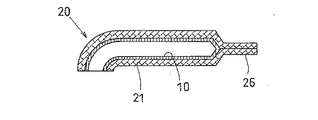
図1に示す中空樹脂コア10は、一端11側は開放し、他端12側は閉鎖し、途中には曲がり部13を有する形状であり、内部は空間14となっている。中空樹脂コア10は、ABS樹脂、PS樹脂、PC樹脂等の熱可塑性樹脂で作られており、好ましくは、後記する繊維強化樹脂中空部品を成形するときの温度で軟化はするが溶融はしない樹脂材料が用いられる。肉厚としては1mm前後のものでよい。真空成形等によって2分割品を作りそれを接着して図示のような形状としてもよく、ブロー成形等によって一体成形したものであってもよい。中空樹脂コア10の寸法は、成形しようとするフランジ付き繊維強化樹脂中空部品50の外形から肉厚分内側にオフセットした寸法であることが望ましい。なお、ここで肉厚分とは、フランジ付き繊維強化樹脂中空部品50における中空部での繊維強化樹脂の厚さをいっている。
The
15は第2のコアであり、この例ではアルミニウム材から作られた中空筒体である。第2のコア15は、その一端側が中空樹脂コア10の閉鎖端12側に適宜の手段で装着できるような形状とされている。長さは成形しようとするフランジ部の長さに応じて設定される。なお、第2のコア15はそこに積層される強化繊維の圧力に耐える材料であれば、アルミニウム材に限らず、樹脂材料等の任意の材料で作ることができる。
図1(b)に示すように、中空樹脂コア10の閉鎖端12側に第2のコア15を仮接合する。その外周に強化繊維を積層して強化繊維層21を形成し、得ようとする繊維強化樹脂中空部品の形状に近似した形状の中空積層体20とする。ここで、強化繊維とは従来知られた繊維強化樹脂で用いられている強化繊維であってよく、例えば、炭素繊維が好適に用いられる。中空樹脂コア10および第2のコア15は、常温あるいは常温以下で行う強化繊維の積層の際には、コア(マンドレル)として十分な剛性を保ち、強化繊維層の肉厚を管理しながら積層することが容易である。中空樹脂コア10および第2のコア15の外周に強化繊維を積層する方法も任意であるが、好ましくは、従来知られたブレイディング法(円筒織り)を用いて、織り角を調整しながら積層する。この際に、中空樹脂コア10の細径部は組角度θを小さく、大径部は組角度θを大きくとることにより、織り目の詰まり状態を制御しながら織り込むことで、隙間のないブレイディング層(強化繊維層)21を形成することができる。
As shown in FIG. 1B, the
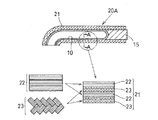
さらに好ましくは、図2に示すように、中空樹脂コア10および第2のコア15の外周に強化繊維を積層するときに、図2のA−A断面に示すように、軸線に対する組角度が0度である組糸層22と、軸線に対する組角度がθ度である組糸層23とを交互に積層する。なお、図では4層の強化繊維層21を示しているが、層の数は任意であり、求められる強度を考慮して適宜な層数とする。この形態の強化繊維層21とすることにより、長手方向の引き張り強度を向上させ、またコントロールすることができる。それにより、同じ強度の中空積層体20をより肉薄の強化繊維層21で形成することができ、軽量化にも資することができる。作業に要する時間も短縮でき、プリプレグを手貼りにより積層する場合には4〜5時間かかる工程を、30分以下に抑えることができる。
More preferably, when the reinforcing fibers are laminated on the outer circumferences of the
図2に示す例では、組糸層22と組糸層23との間に、マトリックス用樹脂フィルム24をさらに積層している。マトリックス用樹脂は、不飽和ポリエステル樹脂、エポキシ樹脂、ポリイミド樹脂等の熱硬化性樹脂でもよく、ポリエチレン、ポリプロピレン、ポリアミド等の熱可塑性樹脂でもよい。得ようとするフランジ付き繊維強化樹脂中空部品50の用途や求められる物性値等を勘案して適宜選択する。例えば、自動車用のピラーをフランジ付き繊維強化樹脂中空部品50で製造する場合には、熱硬化性樹脂を用いることが望ましい。
In the example shown in FIG. 2, a
形成した中空積層体20から、図3に示すように、仮接合しておいた第2コア15を引き抜く。引き抜いた後、中空積層体20における第2コア15が存在していた領域を適宜の手段で上下から押圧し、図4に示すように、フランジ状部分26を形成する。フランジ状部分26は平板状に形成するのが普通であるが、フランジ付き繊維強化樹脂中空部品50の使用態様に応じて曲率を持つ形状、曲がり部を持つ形状等に押圧してもよい。
As shown in FIG. 3, the temporarily bonded
好ましくは、図5に示すように、少なくとも前記フランジ状部分26と中空部分の境界領域に、ミシン等を用いて、縫い込み27を入れる。この縫い込みは図示のようにフランジ状部分26の全域に行ってもよい。縫い込みに用いる糸は、強化繊維層21を形成する糸と同一材質のもの(例えば、炭素繊維)が好ましいが、熱可塑性樹脂等の一般的な糸を用いることもできる。
Preferably, as shown in FIG. 5, at least a boundary region between the flange-shaped
次に、形成した中空積層体20の前記中空樹脂コア10の内部空間14内に、加圧用バッグ30を挿入配置する。加圧用バッグ30は、成形時に加圧用バッグ30内に付与される圧力を、前記した中空樹脂コア10を介して強化繊維層21に伝達する役目を果たすものであり、弾性がありかつ変形が容易な材料、例えば合成ゴムやナイロンシート、ウレタンシート等の樹脂シートのような材料で作られる。加圧用バッグ30の形状は中空樹脂コア10の内面側の形状と一致していることが望ましいが、内圧が掛かることにより変形して中空樹脂コア10の内面に密着できる形状であれば、中空樹脂コア10の内面側の形状に近似した形状であってよい。
Next, the pressurizing
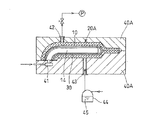
そして、図6に示すように、中空樹脂コア10の内部空間14に加圧用バッグ30を挿入した中空積層体20を、ヒータ(不図示)を備えた成形型40のキャビティ内に配置する。成形型40は、前記中空樹脂コア10の開放した端部11が位置する個所に、加圧空気供給バルブ41を備えると共に、キャビティ空間を真空ポンプPに接続する排気ポート42を備える。また、前記した中空積層体20に形成したフランジ状部分26に対応したキャビティ領域も備える。
And as shown in FIG. 6, the hollow
成形型40を閉じた後、真空ポンプPを作動して、キャビティ内の真空引きを行う。それにより、中空積層体20の強化繊維層21内は脱気される。その状態でヒータを作動し、強化繊維層間に配置したマトリックス用樹脂フィルム24の溶融温度にまで昇温する。それにより、溶融した樹脂は繊維間に含浸していく。樹脂が溶融し含浸を開始した前後に、加圧空気供給バルブ41を開き、加圧用バッグ30に加圧空気を供給する。圧力は、0.1MPa〜1MPa程度であってよく、より高い圧力であってもよい。加圧空気の供給により加圧用バッグ30には内圧がかかり、その圧力は軟化した中空樹脂コア10を介して強化繊維層21を外側に膨出させる。それにより、強化繊維層21はキャビティ内面に押し付けられた姿勢となり、賦形される。この賦形は、前記のように弾性がありかつ変形が容易な材料で作られた加圧用バッグ30から作用する圧力で行われるので、強化繊維層21の中空部分に対応する全域にほぼ等しい圧力が作用し、異形断面を備えた領域においても、肉厚が不均一になることはない。
After closing the
キャビティ内にフランジ状部分26には前記加圧用バッグ30からの圧力は作用せず、型締めによってのみ賦形がなされる。しかし、内圧は、ラフンジ状部分26と中空部分の境界領域に作用し、フランジ状部分26を開く方向に変形させようとする。前記した縫い込み27は、この変形を防止するために設けられる。
The pressure from the pressurizing
マトリックス用樹脂が熱硬化性樹脂の場合には、さらに硬化温度まで昇温し、その温度を保持する。それにより、樹脂は強化繊維との間でマトリックスを組むようにして硬化し、繊維強化樹脂となる。樹脂の硬化終了後、加圧用バッグ30の内圧を抜き、冷却して成形型を開く。成形型から樹脂の硬化したフランジ付き繊維強化樹脂中空部品を取り出し、加圧用バッグ30を除去することにより、本発明による十分に軽量化したフランジ付き繊維強化樹脂中空部品50が得られる。
When the matrix resin is a thermosetting resin, the temperature is further raised to the curing temperature and the temperature is maintained. Thereby, the resin is cured by forming a matrix with the reinforcing fibers, and becomes a fiber-reinforced resin. After the resin is cured, the internal pressure of the pressurizing
図7は、本発明によるフランジ付き繊維強化樹脂中空部品50の成形方法の他の形態で用いる中空積層体20Aを示している。この中空積層体20Aは、マトリックス用樹脂フィルム24を繊維層22、23の間に介装していない点でのみ、図2に示した中空積層体20と相違している。他の構成は同じであってよく、同じ部材には同じ符号を付して説明は省略する。
FIG. 7 shows a
図8は、前記中空積層体20Aを成形型40A内に配置してフランジ付き繊維強化樹脂中空部品50を成形する場合を説明している。ここで、成形型40Aは樹脂注入ポート43を備え、樹脂タンク44からマトリックス用樹脂45が前記ポート43を介してキャビティ内に供給できるようになっている。他の構成は、図6に示した成形型40と同じであり、同じ部材には同じ符号を付して説明は省略する。
FIG. 8 illustrates a case where the hollow
成形に当たっては、中空樹脂コア10の内部空間14内に加圧用バッグ30を挿入した中空積層体20Aを、成形型40Aのキャビティ内に配置する。成形型40を閉じた後、真空ポンプPを作動して、キャビティ内の真空引きを行う。また、その状態でヒータを作動してマトリックス用樹脂45の溶融温度にまで昇温し、樹脂注入ポート43からマトリックス用樹脂45をキャビティ内に供給する。供給されたマトリックス用樹脂45は繊維間に含浸していく。十分な量の樹脂が供給された時点で、樹脂注入ポート43を閉じる。
In molding, the
樹脂供給が開始した前後に、加圧空気供給バルブ41を開き、加圧用バッグ30に加圧空気を供給する等、それ以降の手順は、図6に基づき説明した成形手順と同じであり、説明は省略する。この成形方法によっても、全体にほぼ等しい肉厚でありかつ十分に軽量化したフランジ付き繊維強化樹脂中空部品50を得ることができる。
Before and after the resin supply is started, the subsequent procedure such as opening the pressurized
図9は、中空積層体20をフランジ付き繊維強化樹脂中空部品50として成形するさらに他の例を示している。ここで用いる中空積層体20は図4または図5で説明したものと同じであり、成形型40も図6で説明したものと同じである。ただ、成形に当たって、前記した加圧用バッグ30を用いず、加圧空気供給バルブ41から入り込む加圧空気の圧力を、直接中空樹脂コア10の内面に作用させている点で相違する。中空樹脂コア10が充分な気密性を有している場合には、この成形方法も可能である。この成形方法は、図8に基づき説明した中空積層体20と成形型40Aを用いる成形方法にも適用することができる。
FIG. 9 shows still another example in which the hollow
上記したように、本発明による成形方法で得られるフランジ付き繊維強化樹脂中空部品50は、中空本体部分とフランジ部とが連続する繊維強化樹脂によって一体に作られており、軽量でありながらフランジ部およびその中空本体部分との境界部も含めて高い機械的強度を備えたフランジ付き繊維強化樹脂中空部品50となる。
As described above, the flanged fiber reinforced resin
なお、本発明による成形方法は、3次元的異形断面を有しかつ曲がり部を持つような形状のフランジ付き繊維強化樹脂中空部品50を作るのに特に好適に用いられるが、それに限らず、断面が円形のような単純断面のフランジ付き繊維強化樹脂中空部品50あるいは直線状のフランジ付き繊維強化樹脂中空部品50を作るのにも用いうることは当然である。
The molding method according to the present invention is particularly preferably used to make a flanged fiber-reinforced resin
また、上記の説明では、第2のコア15を筒状のものとして説明したが、フランジとなる領域の周長が一致することを条件に、開放した湾曲板のような形状であってもよい。
Further, in the above description, the
10…中空樹脂コア、11…開放端、12…閉鎖端、13…曲がり部、14…内部空間、15…第2のコア、20、20A…中空積層体、21…強化繊維層(ブレイディング層)、22…軸線に対する組角度が0度である組糸層、23…軸線に対する組角度がθ度である組糸層、24…マトリックス用樹脂フィルム、26…フランジ状部分、27…縫い込み、30…加圧用バッグ、40,40A…成形型、41…加圧空気供給バルブ、42…排気ポート、43…樹脂注入ポート、44…樹脂タンク、45…マトリックス用樹脂、50…フランジ付き繊維強化樹脂中空部品
DESCRIPTION OF
Claims (1)
A fiber-reinforced resin hollow part having one end closed, and a flat flange portion integrally formed by pressing a reinforcing fiber layer at the time of molding the fiber-reinforced resin hollow part at the end of the closed side , the flange portion is flanged fiber-reinforced resin hollow part, characterized that you have placed is sewn to the border region of the hollow portion.
Priority Applications (4)
| Application Number | Priority Date | Filing Date | Title |
|---|---|---|---|
| JP2007200659A JP4429341B2 (en) | 2007-08-01 | 2007-08-01 | Fiber reinforced plastic hollow parts with flange |
| US12/671,178 US8808480B2 (en) | 2007-08-01 | 2008-08-01 | Flanged fiber-reinforced resin hollow part and method of molding the same |
| PCT/JP2008/063837 WO2009017217A1 (en) | 2007-08-01 | 2008-08-01 | Fiber-reinforced resin hollow part with flange and method of forming the same |
| EP08792050.0A EP2186614B1 (en) | 2007-08-01 | 2008-08-01 | Fiber-reinforced resin hollow part with flange and method of forming the same |
Applications Claiming Priority (1)
| Application Number | Priority Date | Filing Date | Title |
|---|---|---|---|
| JP2007200659A JP4429341B2 (en) | 2007-08-01 | 2007-08-01 | Fiber reinforced plastic hollow parts with flange |
Related Child Applications (1)
| Application Number | Title | Priority Date | Filing Date |
|---|---|---|---|
| JP2009095068A Division JP4382869B2 (en) | 2009-04-09 | 2009-04-09 | Molding method of hollow fiber reinforced plastic parts with flange |
Publications (2)
| Publication Number | Publication Date |
|---|---|
| JP2009034885A JP2009034885A (en) | 2009-02-19 |
| JP4429341B2 true JP4429341B2 (en) | 2010-03-10 |
Family
ID=40304446
Family Applications (1)
| Application Number | Title | Priority Date | Filing Date |
|---|---|---|---|
| JP2007200659A Expired - Fee Related JP4429341B2 (en) | 2007-08-01 | 2007-08-01 | Fiber reinforced plastic hollow parts with flange |
Country Status (4)
| Country | Link |
|---|---|
| US (1) | US8808480B2 (en) |
| EP (1) | EP2186614B1 (en) |
| JP (1) | JP4429341B2 (en) |
| WO (1) | WO2009017217A1 (en) |
Families Citing this family (9)
| Publication number | Priority date | Publication date | Assignee | Title |
|---|---|---|---|---|
| JP4384221B2 (en) * | 2007-12-17 | 2009-12-16 | トヨタ自動車株式会社 | Method for molding fiber reinforced resin hollow parts |
| JP2010220748A (en) * | 2009-03-23 | 2010-10-07 | Toyota Industries Corp | Seat frame and method for manufacturing the seat frame |
| JP2011183779A (en) * | 2010-03-11 | 2011-09-22 | Murata Machinery Ltd | Method of producing reinforced fiber preform and reinforced fiber preform |
| DE102010049563B4 (en) * | 2010-10-25 | 2017-09-14 | Daimler Ag | Method for producing a torsion spring |
| JP5977102B2 (en) * | 2012-07-06 | 2016-08-24 | 川崎重工業株式会社 | Railroad vehicle drainage device |
| JP6308427B2 (en) * | 2014-03-31 | 2018-04-11 | 東レ株式会社 | Body structure |
| TWI609773B (en) * | 2015-12-25 | 2018-01-01 | 翁慶隆 | Method for forming a composite pipe and the device thereof |
| JP7082999B2 (en) * | 2020-03-18 | 2022-06-09 | ミズノ テクニクス株式会社 | Molding system for hollow molded products and manufacturing method for hollow molded products |
| CN114434825B (en) * | 2022-01-07 | 2023-08-04 | 深圳市喜德盛碳纤科技有限公司 | Forming device and forming method for carbon fiber frame |
Family Cites Families (29)
| Publication number | Priority date | Publication date | Assignee | Title |
|---|---|---|---|---|
| DE3113791A1 (en) * | 1981-04-04 | 1982-12-02 | Vereinigte Flugtechnische Werke Gmbh, 2800 Bremen | "TUBULAR HOLLOW BODY, PROCESS FOR ITS PRODUCTION AND DEVICE FOR IMPLEMENTING THE PROCESS" |
| JPS5856823A (en) | 1981-09-30 | 1983-04-04 | Kawasaki Heavy Ind Ltd | Production of structure of composite material |
| US4624460A (en) | 1983-03-24 | 1986-11-25 | Nippon Gakki Seizo Kabushiki Kaisha | Golf club head |
| JPS59174169A (en) | 1983-03-24 | 1984-10-02 | ヤマハ株式会社 | Wood club head for golf and production thereof |
| JPS62244620A (en) * | 1986-04-17 | 1987-10-26 | Nippon Kokan Kk <Nkk> | Increasing of thickness of tube end of fiber reinforced plastic tube and device therefor |
| JPH0272935A (en) * | 1988-09-08 | 1990-03-13 | Toyota Motor Corp | Molding method of hollow body made of fibre reinforced plastic |
| JP2671600B2 (en) | 1990-11-14 | 1997-10-29 | 日東紡績株式会社 | Molding method for fiber reinforced plastic |
| JPH04286612A (en) | 1991-03-15 | 1992-10-12 | Hitachi Chem Co Ltd | Manufacture of fiber reinforced plastic molding with flange |
| US5217555A (en) * | 1991-12-09 | 1993-06-08 | Lockheed Corporation | Process for making hollow tubular structural members with integral end attachment fittings |
| JP3398455B2 (en) * | 1993-04-26 | 2003-04-21 | トヨタ自動車株式会社 | Drive shaft manufacturing method and drive shaft coupling device |
| JPH10168699A (en) | 1996-12-06 | 1998-06-23 | Toshiba Corp | Composite fiber material and its production |
| US6171423B1 (en) * | 1998-09-11 | 2001-01-09 | Essef Corporation | Method for fabricating composite pressure vessels |
| FR2793186B1 (en) * | 1999-05-04 | 2001-06-15 | Vetrotex France Sa | HOLLOW COMPOSITE PRODUCTS AND METHOD OF MANUFACTURE |
| JP4227299B2 (en) * | 2000-12-20 | 2009-02-18 | 日機装株式会社 | Manufacturing method of flanged tubular product made of fiber reinforced plastic |
| JP4526698B2 (en) | 2000-12-22 | 2010-08-18 | 富士重工業株式会社 | COMPOSITE MATERIAL AND MANUFACTURING METHOD THEREOF |
| WO2002072337A1 (en) | 2001-03-13 | 2002-09-19 | Ems-Chemie Ag | Non-isothermal method for fabricating hollow composite parts |
| JP2003094448A (en) | 2001-09-25 | 2003-04-03 | Toray Ind Inc | Manufacturing method for frp hollow structure |
| JP3692329B2 (en) | 2002-05-13 | 2005-09-07 | 三菱重工業株式会社 | Strength member, truss structure, and method of manufacturing strength member |
| JP2004017412A (en) | 2002-06-14 | 2004-01-22 | Murata Mach Ltd | Manufacturing method for bent pipe |
| JP2004353134A (en) * | 2003-05-30 | 2004-12-16 | Murata Mach Ltd | Braiding composition base made of broad yarn and method for producing the same |
| US7566376B2 (en) * | 2003-10-01 | 2009-07-28 | Fuji Jukogyo Kabushiki Kaisha | Pressure container manufacturing method |
| FI20031707A0 (en) | 2003-11-24 | 2003-11-24 | Raute Oyj | Method for determining the centering of veneer laths |
| JP2006123475A (en) | 2004-11-01 | 2006-05-18 | Toho Tenax Co Ltd | Molding method of hollow member made of frp profile in its cross section |
| JP2006130875A (en) | 2004-11-09 | 2006-05-25 | Toho Tenax Co Ltd | Inner pressure molding method |
| JP4706244B2 (en) | 2004-12-03 | 2011-06-22 | 東レ株式会社 | FRP hollow structure molding method |
| JP2006305867A (en) | 2005-04-28 | 2006-11-09 | Toray Ind Inc | Manufacturing method of fiber reinforced plastic |
| JP2007152718A (en) | 2005-12-05 | 2007-06-21 | Teijin Techno Products Ltd | Frp molded article, and its molding method |
| JP2007260930A (en) | 2006-03-27 | 2007-10-11 | Toho Tenax Co Ltd | Preform base material and preform manufacturing method |
| JP4384221B2 (en) | 2007-12-17 | 2009-12-16 | トヨタ自動車株式会社 | Method for molding fiber reinforced resin hollow parts |
-
2007
- 2007-08-01 JP JP2007200659A patent/JP4429341B2/en not_active Expired - Fee Related
-
2008
- 2008-08-01 EP EP08792050.0A patent/EP2186614B1/en not_active Not-in-force
- 2008-08-01 US US12/671,178 patent/US8808480B2/en not_active Expired - Fee Related
- 2008-08-01 WO PCT/JP2008/063837 patent/WO2009017217A1/en active Application Filing
Also Published As
| Publication number | Publication date |
|---|---|
| EP2186614A4 (en) | 2015-01-21 |
| JP2009034885A (en) | 2009-02-19 |
| EP2186614B1 (en) | 2016-11-30 |
| EP2186614A1 (en) | 2010-05-19 |
| US20100196639A1 (en) | 2010-08-05 |
| WO2009017217A1 (en) | 2009-02-05 |
| US8808480B2 (en) | 2014-08-19 |
Similar Documents
| Publication | Publication Date | Title |
|---|---|---|
| JP4429341B2 (en) | Fiber reinforced plastic hollow parts with flange | |
| JP4384221B2 (en) | Method for molding fiber reinforced resin hollow parts | |
| US4762740A (en) | Resin transfer molding core, preform and process | |
| JP6369720B2 (en) | Manufacturing method of rack housing | |
| JP4522796B2 (en) | Manufacturing method of fiber reinforced composite material annular structure and annular frame for aircraft fuselage comprising the structure | |
| US20170225413A1 (en) | Method for manufacturing a reinforced part comprising a composite material | |
| WO2017026355A1 (en) | Vibration-proof member and method for manufacturing vibration-proof member | |
| US20190351627A1 (en) | Method for manufacturing multilayer fiber reinforced resin composite and molded product using the same | |
| KR101219397B1 (en) | Method for manufacturing composite hollow structure | |
| JP4382869B2 (en) | Molding method of hollow fiber reinforced plastic parts with flange | |
| CN109664524A (en) | The moulding process of fibre reinforced composites reinforcing beam and the vehicle for using the technique | |
| TW202208223A (en) | Bicycle frame and method for manufacturing | |
| WO2014115668A1 (en) | Method for molding hollow molding and method for manufacturing fiber reinforced plastic | |
| JP2016175211A (en) | Method for manufacturing resin molding, and resin molding | |
| JP4826176B2 (en) | Reinforcing fiber preform and RTM molding method | |
| JP2009107408A (en) | Crash box and method of manufacturing the same | |
| JP2008068553A (en) | Preform for rtm (resin transfer molding) process and rtm processes | |
| US9358733B2 (en) | Method and a device for the manufacture of a fibre composite component, and a fibre composite component | |
| JP4687509B2 (en) | COMPOSITE MATERIAL AND PROCESS FOR PRODUCING THE SAME | |
| US20230264748A1 (en) | Vehicle body pillar structure and vehicle body structure | |
| EP4023422A1 (en) | Method for manufacturing structure and structure | |
| JPH03161326A (en) | Pipe fitted with flange made of fiber reinforced composite material and preparation thereof | |
| JP2013106782A (en) | Golf club shaft | |
| KR101561029B1 (en) | Method manufacturing for helmet | |
| WO2023002205A1 (en) | Method of manufacturing reinforced lightweight composites |
Legal Events
| Date | Code | Title | Description |
|---|---|---|---|
| A521 | Request for written amendment filed |
Free format text: JAPANESE INTERMEDIATE CODE: A523 Effective date: 20081112 |
|
| A131 | Notification of reasons for refusal |
Free format text: JAPANESE INTERMEDIATE CODE: A131 Effective date: 20090210 |
|
| A521 | Request for written amendment filed |
Free format text: JAPANESE INTERMEDIATE CODE: A523 Effective date: 20090409 |
|
| A131 | Notification of reasons for refusal |
Free format text: JAPANESE INTERMEDIATE CODE: A131 Effective date: 20090908 |
|
| A521 | Request for written amendment filed |
Free format text: JAPANESE INTERMEDIATE CODE: A523 Effective date: 20091106 |
|
| TRDD | Decision of grant or rejection written | ||
| A01 | Written decision to grant a patent or to grant a registration (utility model) |
Free format text: JAPANESE INTERMEDIATE CODE: A01 Effective date: 20091201 |
|
| A01 | Written decision to grant a patent or to grant a registration (utility model) |
Free format text: JAPANESE INTERMEDIATE CODE: A01 |
|
| A61 | First payment of annual fees (during grant procedure) |
Free format text: JAPANESE INTERMEDIATE CODE: A61 Effective date: 20091215 |
|
| FPAY | Renewal fee payment (event date is renewal date of database) |
Free format text: PAYMENT UNTIL: 20121225 Year of fee payment: 3 |
|
| FPAY | Renewal fee payment (event date is renewal date of database) |
Free format text: PAYMENT UNTIL: 20121225 Year of fee payment: 3 |
|
| FPAY | Renewal fee payment (event date is renewal date of database) |
Free format text: PAYMENT UNTIL: 20131225 Year of fee payment: 4 |
|
| R250 | Receipt of annual fees |
Free format text: JAPANESE INTERMEDIATE CODE: R250 |
|
| R250 | Receipt of annual fees |
Free format text: JAPANESE INTERMEDIATE CODE: R250 |
|
| R250 | Receipt of annual fees |
Free format text: JAPANESE INTERMEDIATE CODE: R250 |
|
| LAPS | Cancellation because of no payment of annual fees |