JP4428998B2 - Image processing apparatus and method - Google Patents
Image processing apparatus and method Download PDFInfo
- Publication number
- JP4428998B2 JP4428998B2 JP2003412213A JP2003412213A JP4428998B2 JP 4428998 B2 JP4428998 B2 JP 4428998B2 JP 2003412213 A JP2003412213 A JP 2003412213A JP 2003412213 A JP2003412213 A JP 2003412213A JP 4428998 B2 JP4428998 B2 JP 4428998B2
- Authority
- JP
- Japan
- Prior art keywords
- color
- data
- color space
- output
- value
- Prior art date
- Legal status (The legal status is an assumption and is not a legal conclusion. Google has not performed a legal analysis and makes no representation as to the accuracy of the status listed.)
- Expired - Fee Related
Links
- 238000012545 processing Methods 0.000 title claims description 97
- 238000000034 method Methods 0.000 title claims description 65
- 238000006243 chemical reaction Methods 0.000 claims description 63
- 238000004364 calculation method Methods 0.000 claims description 38
- 239000003086 colorant Substances 0.000 claims description 15
- 238000012937 correction Methods 0.000 claims description 12
- 238000003672 processing method Methods 0.000 claims description 7
- 238000009499 grossing Methods 0.000 claims description 5
- 230000006870 function Effects 0.000 description 16
- 238000010586 diagram Methods 0.000 description 11
- 230000001419 dependent effect Effects 0.000 description 7
- 239000013598 vector Substances 0.000 description 6
- 238000005259 measurement Methods 0.000 description 5
- 238000004737 colorimetric analysis Methods 0.000 description 4
- 230000000694 effects Effects 0.000 description 4
- 238000004590 computer program Methods 0.000 description 2
- 238000007796 conventional method Methods 0.000 description 2
- 230000007423 decrease Effects 0.000 description 2
- 230000003203 everyday effect Effects 0.000 description 2
- 230000007704 transition Effects 0.000 description 2
- 230000002354 daily effect Effects 0.000 description 1
- 238000005516 engineering process Methods 0.000 description 1
- 230000002708 enhancing effect Effects 0.000 description 1
- 238000003384 imaging method Methods 0.000 description 1
- 238000009434 installation Methods 0.000 description 1
- 230000003287 optical effect Effects 0.000 description 1
- 230000002093 peripheral effect Effects 0.000 description 1
- 238000001454 recorded image Methods 0.000 description 1
Images


Classifications
-
- H—ELECTRICITY
- H04—ELECTRIC COMMUNICATION TECHNIQUE
- H04N—PICTORIAL COMMUNICATION, e.g. TELEVISION
- H04N1/00—Scanning, transmission or reproduction of documents or the like, e.g. facsimile transmission; Details thereof
- H04N1/46—Colour picture communication systems
- H04N1/56—Processing of colour picture signals
- H04N1/60—Colour correction or control
- H04N1/603—Colour correction or control controlled by characteristics of the picture signal generator or the picture reproducer
- H04N1/6033—Colour correction or control controlled by characteristics of the picture signal generator or the picture reproducer using test pattern analysis
-
- H—ELECTRICITY
- H04—ELECTRIC COMMUNICATION TECHNIQUE
- H04N—PICTORIAL COMMUNICATION, e.g. TELEVISION
- H04N1/00—Scanning, transmission or reproduction of documents or the like, e.g. facsimile transmission; Details thereof
- H04N1/46—Colour picture communication systems
- H04N1/56—Processing of colour picture signals
- H04N1/60—Colour correction or control
- H04N1/6058—Reduction of colour to a range of reproducible colours, e.g. to ink- reproducible colour gamut
- H04N1/6063—Reduction of colour to a range of reproducible colours, e.g. to ink- reproducible colour gamut dependent on the contents of the image to be reproduced
Description
本発明は、望ましい色再現を行うための画像処理技術に関する。 The present invention relates to an image processing technique for performing desired color reproduction.
近年、出力デバイスのカラー化が進み、色情報を管理するカラーマネージメント技術の重要性が増してきている。モニタ等の入力デバイスとプリンタ等の出力デバイスとでは色の再現範囲が異なるため、入力デバイスの色情報をそのまま出力デバイスの色情報として扱うことができない。また、入力色空間と出力色空間とでは色空間の定義が異なる場合も多い。そこで従来より、入力デバイスの色情報をいったん絶対色空間へと変換し、その絶対色空間の情報を出力デバイスの色空間へと変換することで、入力デバイスのデータを出力デバイスにて出力するということが行われている。 In recent years, colorization of output devices has progressed, and the importance of color management technology for managing color information has increased. Since the color reproduction range differs between an input device such as a monitor and an output device such as a printer, the color information of the input device cannot be handled as it is as the color information of the output device. Also, the definition of the color space is often different between the input color space and the output color space. Therefore, conventionally, the input device data is output to the output device by converting the input device color information into the absolute color space and then converting the absolute color space information into the output device color space. Things have been done.
図1は、入力デバイスから出力デバイスへ画像を出力する際の色空間の遷移を表した図である。入力色空間201はソースプロファイル202によって絶対色空間203へと変換される。そして、絶対色空間203はディスティネーションプロファイル204によって出力色空間205へと変換される。ここで、ソースプロファイル202は入力色空間を絶対色空間に変換するためのプロファイル、ディスティネーションプロファイル204は絶対色空間を出力色空間に変換するためのプロファイルのことを示しており、現在ではICCで定められたICCプロファイルが多く使われている。
FIG. 1 is a diagram illustrating transition of a color space when an image is output from an input device to an output device. The
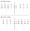
図6は、ICCプロファイルのデータ表現形式について表した図である。図示のとおり、色空間の変換がルックアップテーブル(LUT)で表現されている。同図(A)は、デバイスに依存したCMYKデータをデバイスに依存しないL*a*b*データに変換するためのLUTの例であり、(B)はデバイスに依存しないL*a*b*データをデバイスに依存するCMYKデータに変換するためのLUTの例である。ソースプロファイルの場合は(A)のようなCMYK→L*a*b*のLUTのみを利用し、ディスティネーションプロファイルの場合は(B)のようなL*a*b*→CMYKのLUTのみを利用するが、ICCプロファイルの仕様によれば、片方だけではなく両方のLUTを持つようになっている。 FIG. 6 is a diagram showing the data expression format of the ICC profile. As shown in the figure, the color space conversion is represented by a look-up table (LUT). FIG. 5A shows an example of an LUT for converting device-dependent CMYK data into device-independent L * a * b * data, and FIG. 5B shows a device-independent L * a * b *. It is an example of LUT for converting data into CMYK data depending on a device. In the case of the source profile, only the CMYK → L * a * b * LUT as shown in (A) is used, and in the case of the destination profile, only the L * a * b * → CMYK LUT as shown in (B) is used. Although it is used, according to the specification of the ICC profile, not only one but also both LUTs are provided.
一般には、ICCプロファイルはデフォルトのものが配布または組み込まれている。しかし、どのようなデバイスでも月日が経つと特性が変わってしまうため、その変わってしまった特性に合わせたICCプロファイルを得ることが重要となる。そこで、ICCプロファイルを初めから作成するツールや測色機が多く市場に出回っている。 Generally, a default ICC profile is distributed or incorporated. However, since the characteristics of any device change as time passes, it is important to obtain an ICC profile that matches the changed characteristics. Therefore, many tools and colorimeters for creating ICC profiles from the beginning are on the market.
また、出力デバイスであるプリンタと入力デバイスであるスキャナとを兼ね備えるMFP(Multi Function Peripheral)においては、一次色で構成された濃淡パッチを出力してそれをスキャナで読み込み、一次色についてのキャリブレーションを行うことで上記ICCプロファイルによるカラーマッチングの効果を高める操作が、従来より行われている。 Also, in an MFP (Multi Function Peripheral) that has both a printer as an output device and a scanner as an input device, a shade patch composed of primary colors is output and read by the scanner, and calibration for the primary colors is performed. An operation for enhancing the color matching effect by the ICC profile by performing the above has been conventionally performed.
しかしながら、特に出力デバイスが電子写真方式のプリンタであった場合、日々のデバイスの状態変化が激しいため、同じデバイスで同じプロファイルを用いたとしても日や時間が変わると出力画像が変化してしまい、望ましい色再現が得られないことが非常に多い。 However, especially when the output device is an electrophotographic printer, the state of the device changes daily, so even if the same profile is used on the same device, the output image will change if the date or time changes. Very often, the desired color reproduction cannot be obtained.
また、同様の理由から、複数台のデバイスに対して同じプロファイルを用いて同じデータを出力したとしても、デバイス毎に色の違う画像が出力されてしまうという問題もある。 For the same reason, even if the same data is output to a plurality of devices using the same profile, there is a problem that an image having a different color is output for each device.
従来の技術として一次色の濃淡パッチを用いて出力状態を調整する手法があることを述べたが、この手法は一次色についての色合わせは行えても、複数の色を混ぜ合わせた多次色については色合わせの効果が薄い。 Although it has been described that there is a technique for adjusting the output state using a shade patch of the primary color as a conventional technique, this technique can perform color matching for the primary color, but it is a multi-order color that mixes multiple colors The effect of color matching is weak.
また、上記で述べた初めからICCプロファイルを作り直すツール及び測色機を用いればその時のデバイスの状態に合わせたICCプロファイルができあがるため、望ましい色で画像を出力することが可能だが、従来では多数のパッチを出力して測色を行った後、初めからプロファイルを作り出すための計算を行わなければならないため処理に時間がかかってしまい、電子写真など日々デバイスの状態が変動する機器に簡単に適用することが難しい。 Also, if the tool and colorimeter that recreates the ICC profile from the beginning described above are used, an ICC profile that matches the state of the device at that time can be created. After the patch is output and colorimetry is performed, it takes time to perform the calculation to create a profile from the beginning, so it can be easily applied to devices such as electrophotography where the state of the device fluctuates every day. It is difficult.
したがって、本発明は、時々刻々と変動するデバイスの状態に応じた色変換を容易に行うことができるようにし、もってデバイスから出力される画像を常に望ましい色で出力することができる画像処理装置および方法を提供することを目的とする。 Therefore, the present invention makes it possible to easily perform color conversion according to the state of a device that varies from moment to moment, and thus an image processing apparatus capable of always outputting an image output from the device in a desired color. It aims to provide a method.
また、本発明は、同一のデータを複数台のデバイスで出力したときにそれぞれの出力結果の色がほぼ等しくなるような画像処理装置および方法を提供することを目的とする。 It is another object of the present invention to provide an image processing apparatus and method in which the same output data color is substantially equal when the same data is output by a plurality of devices.
本発明の一側面は画像処理装置に係り、所定の色空間で表現された複数種類の多次色のパッチデータを出力デバイスに出力させる出力手段と、前記出力デバイスから出力された各パッチを測定してデバイス非依存色空間における色値を算出する算出手段と、前記所定の色空間と前記デバイス非依存色空間との対応関係を記述した第1の色変換テーブルに基づいて、前記所定の色空間で表現される多次色のパッチデータを前記デバイス非依存色空間に変換して基準値を求める基準値算出手段と、前記算出手段により算出された色値と、対応する前記基準値との差分を算出する差分算出手段と、前記差分算出手段による算出結果に基づいて、前記デバイス非依存色空間と出力色空間との対応関係を記述した、前記第1の色変換テーブルとは異なる第2の色変換テーブルにおけるデバイス非依存色空間側の格子点データを修正する修正手段と、前記修正された格子点データを用いて出力色空間の値を算出することで前記第2の色変換テーブルを更新する更新手段とを有することを特徴とする。 One aspect of the present invention relates to an image processing apparatus, and outputs output means for outputting patch data of a plurality of types of multi-order colors expressed in a predetermined color space to an output device, and measures each patch output from the output device. And calculating the color value in the device-independent color space and the predetermined color based on the first color conversion table describing the correspondence between the predetermined color space and the device-independent color space. A reference value calculation means for converting a patch data of multi-order colors expressed in space into the device-independent color space to obtain a reference value; a color value calculated by the calculation means; and a corresponding reference value a difference calculating means for calculating a difference, based on the calculation result of the difference calculation means, describing the relationship between the device independent color space and the output color space, different from the first color conversion table Correction means for correcting grid point data on the device-independent color space side in the color conversion table of 2 and the second color conversion table by calculating an output color space value using the corrected grid point data And updating means for updating.
また、本発明の別の側面は画像処理方法に係り、所定の色空間で表現された複数種類の多次色のパッチデータを出力デバイスに出力させるステップと、前記出力デバイスから出力された各パッチを測定してデバイス非依存色空間における色値を算出する算出ステップと、前記所定の色空間と前記デバイス非依存色空間との対応関係を記述した第1の色変換テーブルに基づいて、前記所定の色空間で表現される多次色のパッチデータを前記デバイス非依存色空間に変換して基準値を求める基準値算出ステップと、前記算出ステップで算出した色値と、対応する前記基準値との差分を算出する差分算出ステップと、前記差分算出ステップによる算出結果に基づいて、前記デバイス非依存色空間と出力色空間との対応関係を記述した、前記第1の色変換テーブルとは異なる第2の色変換テーブルにおけるデバイス非依存色空間側の格子点データを修正する修正ステップと、前記修正された格子点データを用いて出力色空間の値を算出することで前記第2の色変換テーブルを更新する更新ステップとを有することを特徴とする。 Another aspect of the present invention relates to an image processing method, the step of causing a plurality of types of multi-order color patch data expressed in a predetermined color space to be output to an output device, and each patch output from the output device. And calculating a color value in a device-independent color space, and a predetermined color conversion table that describes a correspondence relationship between the predetermined color space and the device-independent color space. a reference value calculation step of obtaining a reference value multicolor patch data represented in the color space is converted into the device-independent color space, and color values calculated in the calculation step, said reference value corresponding a difference calculation step of calculating the difference, based on the calculation result of the difference calculation step, describing the relationship between the device independent color space and the output color space, the first color Wherein by calculating different values of the second correction step for correcting the lattice point data of the device-independent color space side in the color conversion table, the output color space using said corrected grid point data from the conversion table And an update step for updating the second color conversion table.
本発明によれば、時々刻々と変動するデバイスの状態に応じた色変換を容易に行うことができ、これにより、画像を常に望ましい色でデバイスから出力させることができる。 According to the present invention, it is possible to easily perform color conversion in accordance with the state of the device that changes from moment to moment, and thereby an image can always be output from the device in a desired color.
また、本発明によれば、同一のデータを複数台のデバイスで出力する際に、それぞれの出力結果の色をほぼ等しくすることができる。 Further, according to the present invention, when the same data is output by a plurality of devices, the colors of the output results can be made almost equal.
以下、図面を参照して本発明の好適な実施形態について詳細に説明する。 DESCRIPTION OF EMBODIMENTS Hereinafter, preferred embodiments of the present invention will be described in detail with reference to the drawings.
<第1の実施形態>
図2は、本実施形態における画像処理システムの構成例を示すブロック図である。この画像処理システムは例えば、それぞれ破線で示されるオフィス10とオフィス20とがインターネット108によって接続された環境で実現される。オフィス10内に構築されたLAN109には、MFP101、MFP102、マネージメントPC104、クライアントPC105、及びProxyサーバ106が、互いに通信可能に接続されている。また、オフィス10内のLAN109とオフィス20内のLAN110はproxyサーバ106を介してインターネット108に接続されている。
<First Embodiment>
FIG. 2 is a block diagram illustrating a configuration example of the image processing system according to the present embodiment. This image processing system is realized, for example, in an environment in which an
MFP101、102はそれぞれ、画像の出力を主に担当する。一方、マネージメントPC104は、例えばUSB111を介して、MFPで出力されたカラーパッチを測色する測色機103と接続し、測色機103より得られた測色値を用いたプロファイルの更新等の画像処理、MFPへのプロファイルのアップロード及びダウンロードを担当する。また、このマネージメントPC104は直結LAN112を介してMFP102と接続されている。また、クライアントPC105、107は、一般のユーザによって操作されるPCで、通常はここで画像データが作成され、ユーザの指示に基づいてその画像データがMFPに送出される。
The MFPs 101 and 102 are mainly responsible for image output. On the other hand, the management PC 104 is connected to, for example, the
図3Aは、マネージメントPC104の構成を示すブロック図である。図示するように、このマネージメントPC全体の制御をつかさどるCPU1、ブートプログラム等を記憶しているROM2、主記憶装置として機能するRAM3をはじめ、以下の構成を備える。
FIG. 3A is a block diagram showing the configuration of the
HDD4はハードディスク装置であって、ここにOSのほか、後述するカラーマネージメント・プログラムおよびパッチデータが格納されている。また、VRAM5は表示しようとするイメージデータを展開するメモリであり、ここにイメージデータ等を展開することでCRT6に表示させることができる。7および8はそれぞれ、各種設定を行うためのキーボードおよびマウスである。9はUSB111を介して測色機103に接続するためのUSBインタフェース、10はLAN109に接続するためのネットワーク・インタフェースである。また、このマネージメントPC104は直結LAN112を介してMFP102と接続されていることは先述したとおりである。
The
図3Bは、MFP102の構成を示すブロック図である。ここではMFP102の構成を説明するが、MFP101も同様の構成である。同図において、301はオートドキュメントフィーダーを含む画像読み取り部で、図示は省略するが、一枚または複数枚の原稿画像を光源で照射し、原稿反射像をレンズで固体撮像素子上に結像し、固体撮像素子からラスター状の画像読み取り信号を例えば600dpiの密度の画像信号を得る。通常の複写機能は、この画像信号をデータ処理部305で記録信号に変換し、これを記録装置303に出力して紙上に画像を形成する、というものである。ここで、複数枚の原稿画像を複写する場合には、記憶装置302にいったん1ページ分の記録データを記憶保持した後、記録装置303に順次出力して紙上に画像を形成することになる。
FIG. 3B is a block diagram illustrating a configuration of the
このMFP102への操作者による指示は、MFPに装備されたキー操作部(図示せず)とマネージメントPC104におけるキーボード7及びマウス8とによって実現される入力装置306から行われ、これら一連の動作はデータ処理装置305内の図示しない制御部で制御される。一方、操作入力の状態表示及び処理中の画像データの表示は表示装置304で行われる。
An instruction to the
記憶装置302は上記のとおりページ単位の記録データを記憶保持するほか、ソースプロファイルならびにディスティネーションプロファイルを記憶している。なお、記憶装置302はマネージメントPCからも制御され、これらMFPとマネージメントPCとのデータの授受及び制御はネットワークインタフェース(IF)307および/または直結LAN112を用いて行われる。
The
また、クライアントPC105から出力されるプリントデータは、LAN109からネットワークIF307を経てデータ処理装置305に入力され、ここで記録可能なラスターデータに変換された後、記録装置302によって紙上に記録画像として形成される。
Also, print data output from the
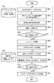
ここで、クライアントPC105からCMYKデータをMFP101、MFP102に送った場合、データ処理部305では図4に示すような処理が行われる。データ処理部305がデータを受け取った際、画像データ401はCMYKで表現されている。これを、ソースプロファイル402を用いて、絶対色空間としてのL*a*b*で表現される画像データ403に変換する。次に、ディスティネーションプロファイル404を用いて、画像データ403を、CMYK’で表現される画像データ405に変換する。ここで、画像データ(CMYK)401と画像データ(CMYK’)405とはデータの次元は同じだが、それぞれ違うデバイスで定義されているため実際の値は異なる。また、このようにソースプロファイル402およびディスティネーションプロファイル404を介さず、406に示すように画像データ(CMYK)401をそのまま画像データ(CMYK’)405として出力することも可能になっている。ただし、この場合はデバイスの特性が反映されないため、意図とは違う画像が出力されてしまうことが多い。
Here, when the CMYK data is sent from the
(処理概要)
次に、本実施形態におけるマネージメントPC104によるプロファイルの調整処理について、図5のフローチャートを用いて説明する。このフローチャートに対応するプログラムはマネージメントPC104のHDD4にインストールされているカラーマネージメント・プログラムに含まれ、RAM3にロードされてCPU1によって実行されるものである。
(Outline of processing)
Next, profile adjustment processing by the
まず、HDD4に保存してあるパッチデータを読み込む(ステップ501)。このパッチデータは100色ほどの多次色で構成されたデータとなっており、CMYKの数値データ及びその画像データとで構成されている。次に、ステップ502で、例えばMFP101にパッチデータの出力を行わせる。この際には、図4におけるソースプロファイル402およびディスティネーションプロファイル404を介さず、画像データ(CMYK)401をそのまま画像データ(CMYK’)405として出力する。そしてステップ503にて、測色機103を用いて、出力されたパッチの測色を行う。その測色結果はUSB111を介してマネージメントPC104に送られ、L*a*b*測色値が算出される(ステップ504)。
First, patch data stored in the
一方、ステップ505において、ICCプロファイルの読み込みを行う。ここでは例えばMFP101において標準で用いられるディスティネーションプロファイルを読み込む。読み込みはMFP101からでもかまわないし、標準に用いられているものであればマネージメントPC内に保存されているものでもかまわない。次に、ステップ506にて、ディスティネーションプロファイル内に含まれる、CMYKをL*a*b*に変換するLUTの取り出しを行う。そして、パッチの数値データとCMYK→L*a*b*変換のLUTとを用いて補間演算を行う(ステップ507)。この補間演算については後ほど詳しく説明する。その後、L*a*b*の基準値を算出する(ステップ508)。一方、ステップ509にて、ディスティネーションプロファイルからL*a*b*→CMYK変換を示すLUTの取り出しを行う。
On the other hand, in
その後、ステップ510にて、L*a*b*測色値、L*a*b*基準値、およびL*a*b*→CMYK変換を示すLUTを用いて、L*a*b*→CMYK変換を示すLUTの更新を行う。後述するように、この更新はLUTを新規に作成するのではなく、元のLUTの必要な箇所を部分的に修正するものである。そのため、パッチデータの数はプロファイルを新規作成する場合と比べて大幅に少なくすることが可能である。よって、測色にかかる時間や演算にかかる時間を新規作成する場合に比べて大幅に軽減することができる。
After that, in
そして、ステップ511にて、この更新されたLUTを用いてディスティネーションプロファイルを更新し、ステップ512で、更新後のディスティネーションプロファイルをMFP101に書き込む。
In
また、同様の処理をMFP101だけではなく、MFP102にも適用することにより、従来電子写真の分野で問題となっていたデバイスの状態の違いによる色差を大幅に軽減することができる。よって、複数台のデバイスで同一のデータを出力させるクラスタプリントを、電子写真などの時間によって色の変化が激しい印刷方式でも行うことが可能となる。ただし、MFP101とMFP102とではできる限り共通のディスティネーションプロファイルを用いることが望ましい。少なくとも、CMYK→L*a*b*変換を示すLUTだけは同一である必要がある。
Further, by applying the same processing not only to the
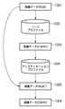
また、上記した処理によって更新されたディスティネーションプロファイルを利用して画像をプリンタで出力する場合、その画像はCMYK画像である必要は無い。図9は実際の印刷時の流れを示したものだが、画像データ901を画像データ(L*a*b*)903に変換するソースプロファイル902が存在すれば、更新されたディスティネーションプロファイル904を用いて画像データ(CMYK)905を作成することができるからである。例えばソースプロファイル902がRGBデータをL*a*b*データに変換するものであれば画像データ901はRGBデータでかまわない。また、更新されたディスティネーションプロファイルが扱う絶対色空間(L*a*b*)に入力色空間を変換するものであるならばソースプロファイルはどのようなものを用いてもかまわない。
Further, when an image is output by a printer using the destination profile updated by the above processing, the image does not need to be a CMYK image. FIG. 9 shows the flow during actual printing. If there is a
また、ディスティネーションプロファイルのL*a*b*→CMYKへの変換を示すLUT、CMYK→L*a*b*への変換を示すLUTは、入力が絶対色空間であればどのような形式でもかまわない。ただし、二つのLUTで同じ定義の絶対色空間を用いている必要がある。また、実際の印刷時にはディスティネーションプロファイルが扱う絶対色空間と同じ絶対色空間への変換を表すLUTを持つソースプロファイルが必要となる。 Further, the LUT indicating the conversion of the destination profile from L * a * b * to CMYK and the LUT indicating the conversion from CMYK to L * a * b * may be in any format as long as the input is an absolute color space. It doesn't matter. However, the two color LUTs must use the same absolute color space. In actual printing, a source profile having an LUT that represents conversion into the same absolute color space as the absolute color space handled by the destination profile is required.
本実施形態におけるマネージメントPCの処理の概要は上記のとおりであるが、以下では、上記処理のうち、ステップ507における補間演算処理、およびステップ510におけるLUTの更新処理について詳しく説明する。
The outline of the processing of the management PC in the present embodiment is as described above. In the following, the interpolation calculation processing in
まず、ステップ507における補間演算処理について説明する。
First, the interpolation calculation process in
(補間演算処理)
ステップ507で行う補間演算は、CMYKパッチデータに対するL*a*b*値の測色値を求めるための処理である。ステップ507を行う前に読み込んだLUTは、CMYKをL*a*b*に変換するためのもので、あるCMYK値の組み合わせに対応したL*a*b*値が記述されている。このLUTを用いて補間演算を行えば、パッチデータのCMYK値に対するL*a*b*値を計算することができるのだが、CMYK色空間では理論上では同じL*a*b*値だとしても、Kの値が異なると実際の値が異なってしまう場合があるので、ここではそれを考慮した補間演算を行う。
(Interpolation calculation processing)
The interpolation calculation performed in
図7は、本実施形態における補間演算処理を示すフローチャートである。 FIG. 7 is a flowchart showing the interpolation calculation process in the present embodiment.
まず、ステップ701にて、CMYK→L*a*b*変換を行うLUTを抽出する。次に、ステップ702にて、Kの値を基準としたグループ化を行う。一般にプロファイルのLUTは入力側が段階的に増えることが多い。例えばC,M,Y,Kがそれぞれ17段階であるとすると、Kの値を基準にしてグループ化した場合、17個のグループができることになる。
First, in
一方、ステップ703にてパッチデータの抽出を行う。これは一つのパッチのCMYK値を抽出する操作である。そしてステップ704にて、取り出したC,M,Y,K値のうちKに着目する。これをK1とする。
On the other hand, in
次に、グループ化したLUTのKの値に着目する。そして、K1の値を囲むようなグループを2つ取り出す(ステップ705)。例えば色の階調が256段階で17段階のLUTがありK1が20である場合、K=16のグループとK=32のグループを取り出す。ここで、Kの値が小さいグループをKa、Kの値が大きいグループをKbとする。そして、Ka、KbそれぞれのグループについてCMYの値を用いた線形補間を行う。この際の線形補間では三次元の既知の手法を用いることができる(ステップ706、ステップ707)。その後、ステップ708にて、Ka、Kbの線形補間結果に対して、Ka、Kbの値を使って一次元の線形補間を行う。
Next, attention is focused on the value of K of the grouped LUT. Then, two groups surrounding the value of K1 are extracted (step 705). For example, when the color gradation is 256 steps, there is a 17-step LUT, and K1 is 20, a group of K = 16 and a group of K = 32 are extracted. Here, a group with a small K value is Ka, and a group with a large K value is Kb. Then, linear interpolation using CMY values is performed for each of Ka and Kb groups. In this case, a known three-dimensional method can be used for the linear interpolation (
このようにしてパッチデータの基準値が出力される。また、ステップ709により、すべてのパッチデータに対して処理が行われていないと判定された場合はステップ703へと戻り処理を繰り返す。すべてのデータに対して処理が行われたと判断された場合は処理を終了する。
In this way, the reference value of the patch data is output. If it is determined in
以上説明した補間演算処理によれば、ディスティネーションプロファイルのCMYKからL*a*b*への変換を行うLUTを利用し、またKの値に対して特別な処理を行うことによってパッチデータに対する基準値を求めることができる。この結果はL*a*b*→CMYKを示すLUTを更新するステップ510にて利用される。
According to the interpolation calculation processing described above, the reference for patch data is obtained by using the LUT for converting the destination profile from CMYK to L * a * b * and by performing special processing on the value of K. The value can be determined. This result is used in
(L*a*b*→CMYK変換を示すLUTの更新処理)
ディスティネーションプロファイルは実際の印刷時に絶対色空間のデータを出力デバイスの色空間に変換する部分を担当する。よって、デバイスの不安定性により出力結果が異なるというのは、ディスティネーションプロファイルのL*a*b*→CMYK変換を示すLUTが適切ではないためであると言うことができる。よって、L*a*b*→CMYK変換を示すLUTの更新を行うステップ510は本発明の中でも特に重要な部分となる。
(LUT update processing indicating L * a * b * → CMYK conversion)
The destination profile is responsible for converting the data in the absolute color space into the color space of the output device during actual printing. Therefore, it can be said that the output result varies depending on the instability of the device because the LUT indicating the L * a * b * → CMYK conversion of the destination profile is not appropriate. Therefore, step 510 for updating the LUT indicating the L * a * b * → CMYK conversion is a particularly important part of the present invention.
以下、L*a*b*からCMYKへの変換を示すLUTの更新処理の実施例について図8のフローチャートを用いて詳しく説明する。 Hereinafter, an embodiment of LUT update processing indicating conversion from L * a * b * to CMYK will be described in detail with reference to the flowchart of FIG.
まず、ステップ801にて、L*a*b*からCMYKへの変換を示すLUTのL*a*b*データ側を取り出す。ここで、L*a*b*データは増分が固定している格子点データであると考えることができる。図11は、L*a*b*空間上に格子点データが存在している例を示す図である。例えばL*a*b*各33段階のLUTであった場合、このステップ801では、33×33×33個ある格子点のうちの一つを取り出すということになる。
First, in
次にステップ802にて、各パッチデータの測色値及び基準値812をすべて取り出し、ステップ801で取り出したL*a*b*値と最も値が近い基準値を算出する。図12に例を示す。基準値や測色値はL*a*b*データなので、図に示すように格子点空間の中に存在している。図12の例では基準値1と基準値2が存在するが、注目されている格子点データCにとって最も近い基準値は基準値1の方なのでそちらが選ばれる。
Next, in
そしてステップ803に進み、ステップ802で算出された基準値と、測色値との差(距離)を計算する。そして、この値を用いてL*a*b*データを修正することができる。ただし、パッチデータの数が少ないと、格子点データから距離が大きく離れた基準値が取り出されることが多くなる。このような基準値に大きく影響をうけることは望ましくないため、本実施形態では、基準値と取り出されたL*a*b*データとの距離を算出し、それに応じた重み付けを行う(ステップ804)。たとえば、距離には三次元空間上でのユークリッド距離を用い、重みは以下の式を用いる。
In
W=1/(dist5+1)
ただし、Wは重み、distは基準値との距離を格子点3つ分の距離で正規化したものを表す。
W = 1 / (dist 5 +1)
Here, W represents a weight, and dist represents a distance normalized to a reference value normalized by a distance corresponding to three grid points.
以上の処理をすべてのLUTのL*a*b*値に対して繰り返す(ステップ805)。 The above processing is repeated for all LUT L * a * b * values (step 805).
ステップ805までの処理により、すべてのL*a*b*格子点データに対して基準値と測色値との差が求まった。図13は全ての格子点に対して基準値と測色値との差を求めた結果を模式的に表した図であり、矢印は測色値から基準値への方向ベクトルを表す。この方向ベクトルの分だけ格子点のL*a*b*値をずらすことでLUTを更新できるのだが、影響の受ける基準値の違いにより、極端な方向・大きさの方向ベクトルが存在する可能性がある。図13の例では丸で示した方向ベクトルVが、周りの他の方向ベクトルに比べて極端な大きさを持つものとなっている。このようなベクトルが存在した場合は、更新した格子点のL*a*b*値が極端なものとなり擬似輪郭の原因となる。そこで、次にこの差に対してスムージング処理(ステップ806)を行うことにより、L*a*b*格子点データの更新が極端になることを防ぐ。スムージングの方法の例としては、注目格子点を中心として、5×5×5の範囲の格子点での値を合計し、その平均を算出する方法や、さらに注目格子点を数倍してから平均を算出する方法などが挙げられる。 Through the processing up to step 805, the difference between the reference value and the colorimetric value is obtained for all L * a * b * grid point data. FIG. 13 is a diagram schematically showing the result of obtaining the difference between the reference value and the colorimetric value for all the grid points, and the arrow represents the direction vector from the colorimetric value to the reference value. Although the LUT can be updated by shifting the L * a * b * values of the grid points by this direction vector, there may be extreme direction / size direction vectors due to differences in the affected reference values. There is. In the example of FIG. 13, the direction vector V indicated by a circle has an extremely large size as compared with other surrounding direction vectors. When such a vector exists, the L * a * b * value of the updated lattice point becomes extreme, causing a pseudo contour. Therefore, a smoothing process (step 806) is then performed on this difference to prevent the L * a * b * lattice point data from being extremely updated. As an example of the smoothing method, the values at the grid points in the range of 5 × 5 × 5 centering on the target lattice point are summed up, and the average is calculated, or the target lattice point is further multiplied several times. For example, a method of calculating an average.
そしてステップ807にて、スムージングをかけた基準値と測色値との差をL*a*b*格子点データに加えていくことで格子点データを更新する。
In
次に、ステップ808にて、変更後のL*a*b*データを一つ取り出す。変更されたL*a*b*データに対するCMYK値がわかればディスティネーションプロファイルのL*a*b*→CMYK変換を示すLUTの更新が可能となる。そこで、更新前のL*a*b*→CMYKを示すLUT813がL*a*b*からCMYKへの変換を記述するLUTであることを利用して、更新されたL*a*b*値に対して三次元の線形補間演算を行う(ステップ809)。例として、図6の(B)に示すようなLUTが挙げられるが、このように入力がL*a*b*となっているので、入力がCMYKの場合とは異なり特別な処理を行う必要がなく、公知の三次元の線形補間手法を適用すればよい。以上の処理を、更新後のすべてのL*a*b*データに対して行う(ステップ810)。
Next, in
このようにして新しいL*a*b*値とそれに対応したCMYK値が求まったので、その結果を用いてL*a*b*→CMYKを示すLUTを更新する(ステップ811)。 Since the new L * a * b * value and the corresponding CMYK value are obtained in this way, the LUT indicating L * a * b * → CMYK is updated using the result (step 811).
(パッチの数について)
パッチの数を約100色用いると説明したが、必ずしもこの数でなければならないとは限らない。ただし、絶対色空間において各色が近づいている状態はあまり望ましくなく、各色がそれぞれ適度に距離が離れていることが望ましい。ここで、パッチの数が多ければ多くなるほど測色等に時間がかかるため、全体の処理速度が低下してしまうが、その代わりに精度は高くなる。また、パッチの数が少なくなればなるほど精度は低くなるが、全体の処理は高速化される。ここで、パッチの数は多すぎても少なすぎても適切な効果は得られないが、従来のプロファイルを新規に作り出す手法に比べれば、本発明は元のプロファイルにおける必要なデータ部分のみを修正する手法であるため大幅に少ないパッチ数で処理を行うことが可能となる。
(About the number of patches)
Although it has been described that the number of patches is about 100, this number is not necessarily limited. However, it is not desirable that the colors are close to each other in the absolute color space, and it is desirable that the colors are appropriately separated from each other. Here, as the number of patches increases, it takes time for color measurement and the like, so the overall processing speed decreases, but the accuracy increases instead. Also, the smaller the number of patches, the lower the accuracy, but the overall processing is speeded up. Here, if the number of patches is too large or too small, an appropriate effect cannot be obtained, but the present invention corrects only the necessary data part in the original profile as compared with the method of newly creating a conventional profile. Therefore, it is possible to perform processing with a significantly smaller number of patches.
(ディスティネーションプロファイルにてCMYKを直接扱えない場合の別実施形態)
上述の実施形態ではL*a*b*→CMYK変換を示すLUTを持つディスティネーションプロファイルを用いた例を記述したが、プリンタによっては直接L*a*b*→CMYK変換を行うディスティネーションプロファイルを持たないものがある。図10は、ディスティネーションプロファイルの絶対色空間→出力色空間を示すLUTがL*a*b*→RGBである場合のデータの流れを示した図である。ここで、ソースプロファイル1002は画像データ(RGB)1001を画像データ(L*a*b*)1003に変換するためのプロファイル、ディスティネーションプロファイル1004は画像データ(L*a*b*)1003を画像データ(RGB’)1005に変換するためのプロファイルである。画像データ(RGB’)1005はデバイスに依存したRGBデータであり、プリンタがRGBプリンタならばこの段階で出力し、CMYKプリンタならば画像データ(RGB’)1005を画像データ(CMYK)1006に変換して出力する。
(Another embodiment when CMYK cannot be handled directly in the destination profile)
In the above-described embodiment, the example using the destination profile having the LUT indicating the L * a * b * → CMYK conversion is described. However, depending on the printer, the destination profile for directly performing the L * a * b * → CMYK conversion may be used. There is something I don't have. FIG. 10 is a diagram showing a data flow when the LUT indicating the absolute color space of the destination profile → the output color space is L * a * b * → RGB. Here, the
ここでは、CMYKデータの場合と同様に画像データ(RGB)1001を直接画像データ(RGB’)1005として扱うことも可能になっている。プリンタがRGBプリンタであった場合は、プロファイル1003,1004を介さずにそのまま出力して測色して測色値を求める。一方、パッチのデータとディスティネーションプロファイルに含まれているRGB→L*a*b*を示すLUTを用いて基準値を算出する。ここで、CMYKではKの値が特殊であったため、特別な補間方法を用いる必要があったが、この場合はそれに相当するものがないため、そのままRGBで三次元の線形補間を行う。
Here, the image data (RGB) 1001 can be directly handled as the image data (RGB ′) 1005 as in the case of CMYK data. When the printer is an RGB printer, the colorimetric value is obtained by outputting the color as it is without going through the
そして、測色値、基準値、ディスティネーションプロファイルのL*a*b*→RGBを示すLUTを利用することでディスティネーションプロファイルを更新することができる。CMYKプリンタの場合は画像データ(RGB’)1005を画像データ(CMYK)1006に変換する部分により精度が変化してしまうが同様に測色値を求め、適用することが可能である。 The destination profile can be updated by using the LUT indicating L * a * b * → RGB of the colorimetric value, the reference value, and the destination profile. In the case of a CMYK printer, the accuracy changes depending on the portion where the image data (RGB ′) 1005 is converted into the image data (CMYK) 1006, but the colorimetric values can be similarly determined and applied.
このように、ディスティネーションプロファイルが入力色空間から絶対色空間へと変換するLUTと、絶対色空間から出力色空間へと変換するLUTを持っており、それらのLUTが扱う入力色空間と出力色空間が同じ種類のものであれば色空間の種類に関わらず本発明を適用可能である。 As described above, the destination profile has an LUT for converting from the input color space to the absolute color space, and an LUT for converting from the absolute color space to the output color space, and the input color space and output color handled by those LUTs. The present invention can be applied regardless of the type of color space as long as the spaces are of the same type.
(L*a*b*からCMYKへの変換を示すLUTの更新処理の別実施例)
以下、L*a*b*からCMYKへの変換を示すLUTの更新処理(ステップ510)の別実施例について説明する。
(Another embodiment of LUT update processing indicating conversion from L * a * b * to CMYK)
Hereinafter, another embodiment of the LUT update process (step 510) indicating conversion from L * a * b * to CMYK will be described.
図14は、L*a*b*からCMYKへの変換を示すLUTの更新処理の別実施例を示すフローチャートである。まず、LUTのL*a*b*データを取り出す(ステップ1401)。次に、予め算出した基準値と測色して求めた測色値1414を読み込み、ステップ1402で条件範囲の決定を行う。ここで条件範囲とは、取り出したLUTの格子点を中心としたある一定の範囲をいい、次のステップ1403にてその範囲内に基準値が入っているかいないかの判定を行う。そして基準値が条件範囲の中に含まれている場合はすべての基準値と測色値を求め(ステップ1405)、その差の平均を算出する(ステップ1415)。例を図15に示す。同図(A)に示されるL*a*b*空間内の格子点データがステップ1401で取り出されたL*a*b*データである。(B)に示される直方体が、ステップ1402で設定される条件範囲である。この例では条件範囲が5×5×5の格子点分の大きさで設定される。図の例では基準値1,2の2つの基準値が条件範囲に含まれているため、それぞれ測色値との差を求めて平均を算出する。このようにすることにより、前述した実施例でのスムージング処理と同様の効果が得られ擬似輪郭を防止することが可能となる。
FIG. 14 is a flowchart illustrating another example of the LUT update process indicating conversion from L * a * b * to CMYK. First, L * a * b * data of the LUT is extracted (step 1401). Next, a
ステップ1403の条件分岐で基準値が範囲内に存在しないと判定された場合は、最も距離が近い基準値を算出し(ステップ1404)、その基準値と測色値との差を算出して距離に応じて重み付けする(ステップ1406)。例として、前述した例と同様に、距離は三次元空間上でのユークリッド距離を用い、重みは以下の式を用いる。
If it is determined in the conditional branch of
W=1/(dist5+1)
ただし、Wは重み、distは基準値との距離を格子点3つ分の距離で正規化したものを表す。
W = 1 / (dist 5 +1)
Here, W represents a weight, and dist represents a distance normalized to a reference value normalized by a distance corresponding to three grid points.
ここで、条件範囲外のものは色再現範囲外のデータであることが多いことから重みは一律の値(例えば四分の一等)でもかまわない場合も多い。 Here, since data outside the condition range is often data outside the color reproduction range, the weight may be a uniform value (for example, a quarter or the like) in many cases.
以上の操作をすべて行った後は、先述の例と同様に、算出した値を用いてすべてのL*a*b*格子点データに対して変更処理を行い(ステップ1409)、その変更したL*a*b*データを一つ取り出し(ステップ1410)、更新前のL*a*b*→CMYK変換を示すLUT1408を用いてステップ1411にて線形補間(三次元)によるCMYKデータの算出を行う。最後にすべてのデータに対して処理を行ったのかを判定し(ステップ1412)、処理を行った場合はステップ1413にてL*a*b*→CMYKを示すLUTの更新処理を行う。
After all of the above operations are performed, the change processing is performed on all L * a * b * grid point data using the calculated values (step 1409), as in the previous example, and the changed L One * a * b * data is extracted (step 1410), and CMYK data is calculated by linear interpolation (three-dimensional) in
このようにすることにより、前述した例と同様にL*a*b*→CMYKを示すLUTを更新することが可能となる。 By doing so, it is possible to update the LUT indicating L * a * b * → CMYK as in the above-described example.
以上説明した第1の実施形態によれば、プロファイル内に含まれる入力色空間で定義されたデータを絶対色空間で定義されたデータに変換するLUTを用いて算出した基準値と、測色して得られた測色値と、絶対色空間で定義されたデータを出力色空間で定義されたデータに変換するLUTとを用いることによって、絶対色空間で定義されたデータを出力色空間に変換するプロファイルを更新することが可能となり、その時の状態に出力結果が左右されやすいデバイスに対しても最適なカラーマッチングを行うことが可能となる。この場合のプロファイルの更新は、プロファイルの新規作成ではなく、元のプロファイルの一部を変更することで済ますことができるので、従来のプロファイルをすべて作り直す手法に比べると、パッチの数を少なくすることができ、また処理が簡易になるので、プロファイルの更新に係る処理時間を大幅に縮小することが可能となる。 According to the first embodiment described above, the reference value calculated using the LUT for converting the data defined in the input color space included in the profile into the data defined in the absolute color space, and the colorimetry are performed. Data defined in the absolute color space is converted into the output color space by using the colorimetric values obtained in this way and the LUT that converts the data defined in the absolute color space into the data defined in the output color space. The profile to be updated can be updated, and optimal color matching can be performed even for a device whose output result is easily affected by the state at that time. In this case, updating the profile can be done by changing a part of the original profile instead of creating a new profile, so the number of patches is reduced compared to the method of recreating all the existing profiles. Since the processing can be simplified, the processing time for updating the profile can be greatly reduced.
また、上述の実施形態のプロファイルの更新処理を、複数台のデバイスに適用することにより、すべてのデバイスにおいて最適なカラーマッチングが行え、従来手法の問題点であった複数台プリントにおけるデバイスごとの色差を大幅に軽減することが可能となる。 In addition, by applying the profile update processing of the above-described embodiment to a plurality of devices, optimal color matching can be performed on all devices, and the color difference for each device in a plurality of devices that has been a problem of the conventional method. Can be greatly reduced.
<第2の実施形態>
先述したとおり、初めからICCプロファイルを作り直すツール及び測色機を用いればその時のデバイスの状態に合わせたICCプロファイルができあがるため、望ましい色で画像を出力することが可能だが、多数のパッチを出力して測色を行った後、初めからプロファイルを作り出すための計算を行わなければならないため処理時間がかかってしまい、電子写真など日々デバイスの状態が変動する機器に関しては簡単に適用することが難しい。特に、ユーザがある限定された画像のみを出力したいという状況では、使用される色が限定されるにもかかわらずプロファイル一から作成することは作業効率が非常に悪いと言える。
<Second Embodiment>
As mentioned earlier, using a tool and a colorimeter that recreates an ICC profile from the beginning will produce an ICC profile that matches the state of the device at that time, so it is possible to output an image in the desired color, but output many patches. After the color measurement is performed, calculation for creating a profile must be performed from the beginning, which takes processing time, and it is difficult to easily apply to a device such as an electronic photograph whose device state fluctuates every day. In particular, in a situation where the user wants to output only a limited image, it can be said that it is very inefficient to create from a profile even though the colors used are limited.
そこで本実施形態では、ユーザの指定した特定の画像の色分布を分析し、その中で主に使われる色のみ抽出し、これにより、数が少なくてかつ最適なパッチを出力できるようにする。また、ここでは上述の第1の実施形態と同様に、ICCプロファイルを初めから作成するのではなく、元のプロファイルを修正することにより、作成した数の少ないパッチでプロファイルを更新することができ、もって処理時間の削減を実現する。 Therefore, in the present embodiment, the color distribution of a specific image designated by the user is analyzed, and only the colors mainly used in the image are extracted, so that the optimum number of patches can be output. Also, as in the first embodiment described above, instead of creating an ICC profile from the beginning, the original profile can be modified to update the profile with a smaller number of created patches. As a result, processing time can be reduced.
本実施形態における画像処理システムの構成、ならびにマネージメントPCおよびMFPの構成はそれぞれ、図2、図3A、図3Bと同様であるので、これら図2、図3A、図3Bを援用することにする。 Since the configuration of the image processing system and the configuration of the management PC and MFP in this embodiment are the same as those in FIGS. 2, 3A, and 3B, these FIGS. 2, 3A, and 3B will be used.
本実施形態では、クライアントPC105からCMYKデータをMFP101、MFP102に送った場合、データ処理部305では図16に示すような処理が行われる。データ処理部305がデータを受け取った際、画像データ1601はCMYKで表現されている。これを、ソースプロファイル1602を用いて、絶対色空間としてのL*a*b*で表現される画像データ1603に変換する。次に、ディスティネーションプロファイル1604を用いて、画像データ1603を、CMYK’で表現される画像データ1605に変換する。ここで、画像データ(CMYK)1601と画像データ(CMYK’)1605とはデータの次元は同じだが、それぞれ違うデバイスで定義されているため実際の値は異なる。また、例外処理として、ソースプロファイル1602およびディスティネーションプロファイル1604を介さず、1610に示すように画像データ(CMYK)1601をそのまま画像データ(CMYK’)1605として出力することも可能になっている。ただし、この場合はデバイスの特性が反映されないため、意図とは違う画像が出力されてしまうことが多い。
In this embodiment, when CMYK data is sent from the
また、上記の色変換機能はマネージメントPC104やクライアントPC105、107で実現することも可能である。さらに、RGBで表現された画像データ1606を入力とした場合でも、ソースプロファイル1607でL*a*b*の画像データに変換され、以下同様の処理が行われる。ただし、出力デバイスの色空間がCMYKであるため、1610の如く直接RGBを出力することはできない。
The color conversion function described above can also be realized by the
(処理概要)
次に、本実施形態におけるマネージメントPC104によるプロファイルの調整処理について、図17のフローチャートを用いて説明する。このフローチャートに対応するプログラムはマネージメントPC104のHDD4にインストールされているカラーマネージメント・プログラムに含まれ、RAM3にロードされてCPU1によって実行されるものである。
(Outline of processing)
Next, profile adjustment processing by the
まず、例えばクライアントPC105からそのユーザの指示に基づき出力される画像データを読み込む(ステップ1701)。次にステップ1702で、ユーザの要求を受け取る。この要求は最終的に出力するパッチの個数にかかわるものであり、ユーザから高精度な色補正を希望された場合は数が多くなり、補正する際の速度を重視した場合は数が少なくなる。
First, for example, image data output from the
次にステップ1703に進み、ステップ1701で読み込んだ画像データの全画素データを、デバイスに依存しない絶対色空間(例えば、L*a*b*)に変換する。一般に、出力する際の画像データはRGBやCMYKといったデバイスに依存した色空間で定義される。これらは色空間内の距離に応じて人間からの見た目が変わるといったものではないため、この後の処理で行うクラスタリング処理においては適切ではない。それに対してL*a*b*等に代表される絶対色空間は距離に応じて見た目の色が変わるため、この後のクラスタリング処理にふさわしいものであるということができる。よって、このステップ1703の処理は必須である。ここで、本実施形態ではL*a*b*を利用するが、デバイスに依存しないものであればどの色空間を用いても問題はない。
In
次にステップ1704で、クラスタリング処理を利用してユーザの要望を満たすパッチ数分の代表値を算出する。これにより、ユーザの要望を満たす数のL*a*b*データが出力される。そしてこのデータをステップ1705で出力色空間の形式に変換し、次のステップ1706で出力する。
In step 1704, representative values for the number of patches that satisfy the user's request are calculated using clustering processing. As a result, a number of L * a * b * data satisfying the user's request is output. This data is converted into the output color space format in
そして、ステップ1707で、ユーザによって印刷を要求されたすべての画像データに対して処理を行ったかどうかを判断し、すべての画像データに対して処理を行った場合はステップ1708へ進み、そうではない場合はステップ1701へ戻り処理を繰り返す。
In
ステップ1708では、類似データの削除を行う。複数枚の画像に対して処理を行った場合は類似した色データが出力される場合がある。このようなデータが存在すると処理時間がかかってしまうため、削除する必要がある。
In
次にステップ1709で、パッチ画像の作成を行う。本実施形態ではCMYKで出力するプリンタに関するものであるため、ここではCMYKパッチを作成する。CMYK以外の色を用いて出力するプリンタである場合はその出力色空間に合わせたパッチを作成することになる。
In
最後にステップ1710で、プロファイルの更新処理を行う。ここでは上記の処理で作成されたパッチデータを用いる。これにより、プロファイルの必要な箇所だけを修正することを可能にする。このステップ1710は第1の実施形態で説明した図5のフローチャートに従う処理に相当する。したがって、このステップ1710の具体的な処理については第1の実施形態の説明を参照されたい。
Finally, in
本実施形態におけるマネージメントPCの処理の概要は上記のとおりであるが、以下では、ステップ1702〜1705の各処理についてより具体的に説明する。
The outline of the processing of the management PC in the present embodiment is as described above. Hereinafter, each processing in
(ステップ1702:ユーザ要求の受信について)
まず、ステップ1702のユーザ要求の受信について説明する。
(Step 1702: Reception of user request)
First, reception of a user request in
ステップ1702ではユーザ要求の受信を行う。上記したとおり、このユーザ要求には、ユーザが色再現の精度を重視するか、色補正にかかる時間を短くするかの情報が含まれる。LUTを書き換える処理を考えた場合、一般には、パッチの数が多いほど色再現の精度は上がるが処理時間が増大し、逆に、パッチの数が少ないほど処理時間は短くて済むが色再現の精度は劣化すると。そこで、そのようなトレードオフの関係を利用して、図18に示すようなUI画面を提示することによってユーザに要求の決定を促す。図18では、色再現精度と処理速度のトレードオフの関係がスライドバーの形式で表示されており、ユーザは例えばマウスを用いて三角形のポインタをスライドさせることで色再現精度および処理速度を指定することができる。たとえば、処理速度がかかっても色再現性を重視したいという場合はポインタを右側に、色再現性は高くなくてよいが、処理速度を早くしたいという場合はポインタを左側に位置させる。この位置情報がユーザ要求としてステップ1704のクラスタリング処理で用いられる。
In
(ステップ1703:絶対色空間への変換処理)
ステップ1703では、デバイスに依存した色空間をデバイスに依存しない色空間へ変換するための処理を行う。変換方法としてはどのようなものを用いてもかまわないが、ここではLUTを用いて補間する方法について説明する。
(Step 1703: Conversion to absolute color space)
In
ICCプロファイルの中にはデバイスに依存した色空間をデバイスに依存しない色空間(絶対色空間)へと変換するLUTと、デバイスに依存しない色空間をデバイスに依存した色空間へと変換するLUTがある。そこで、このLUTを用いて補間演算を行うことで色変換を行う。ここでは特にソースプロファイルとして使用されているLUT(デバイスに依存した色空間→デバイスに依存しない色空間)を用いる。実際の印刷過程で用いられているLUTを使用したほうが最適なパッチを出力できるからである。 Among the ICC profiles, there are an LUT for converting a device-dependent color space into a device-independent color space (absolute color space), and an LUT for converting a device-independent color space into a device-dependent color space. is there. Therefore, color conversion is performed by performing an interpolation operation using this LUT. Here, an LUT (a device-dependent color space → a device-independent color space) used as a source profile is used. This is because an optimum patch can be output by using the LUT used in the actual printing process.
画像データの色空間がRGBである場合は公知の手法の補間演算を行えばよいが、CMYKの場合だと理論上は同じL*a*b*値だとしても、Kの値によって実際の色が大きく異なる場合があるので、ここではそれを考慮した補間演算を行う。 When the color space of the image data is RGB, a known method of interpolation may be performed. However, in the case of CMYK, even if the L * a * b * value is theoretically the same, the actual color depends on the value of K. Since there are cases in which there is a large difference, interpolation calculation is performed in consideration of this.
図19は、本実施形態における補間演算処理を示すフローチャートである。 FIG. 19 is a flowchart showing the interpolation calculation processing in this embodiment.
まず、ステップ1901で、受け取った画像データがCMYK画像であるか否かの判定を行う。ここでもし、CMYK画像でない場合はステップ1902へと進み、公知の手法で線形補間を行う。例えば画像データがRGBデータである場合はRGB→L*a*b*のLUTを取り出して三次元での線形補間を行い、処理を終了する。読み込んだデータがCMYKデータである場合はステップ1903に進み、CMYK→L*a*b*変換を行うLUTを抽出する。
First, in
次に、ステップ1904で、Kの値を基準としたグループ化を行う。一般にプロファイルのLUTは入力側が段階的に増えることが多い。例えばC,M,Y,Kがそれぞれ17段階であるとすると、Kの値を基準にしてグループ化した場合、17個のグループができることになる。
Next, in
一方、ステップ1905にて、画像データから画素データの取り出しを行う。ここではすべての画素データをL*a*b*に変換する必要がある。そしてステップ1906にて、取り出したC,M,Y,K値のうちKに着目する。これをK1とする。
On the other hand, in
次に、グループ化したLUTのKの値に着目する。そして、K1の値を囲むようなグループを2つ取り出す(ステップ1907)。例えば色の階調が256段階で17段階のLUTがありK1が20である場合、K=16のグループとK=32のグループを取り出す。ここで、Kの値が小さいグループをKa、Kの値が大きいグループをKbとする。そして、Ka、KbそれぞれのグループについてCMYの値を用いた線形補間を行う。この際の線形補間では三次元の既知の手法を用いることができる(ステップ1908、ステップ1909)。その後、ステップ1910にて、Ka、Kbの値を使って一次元の線形補間を行う。
Next, attention is focused on the value of K of the grouped LUT. Then, two groups surrounding the value of K1 are extracted (step 1907). For example, when the color gradation is 256 steps, there is a 17-step LUT, and K1 is 20, a group of K = 16 and a group of K = 32 are extracted. Here, a group with a small K value is Ka, and a group with a large K value is Kb. Then, linear interpolation using CMY values is performed for each of Ka and Kb groups. In this case, a known three-dimensional method can be used for the linear interpolation (
このようにして画素値がL*a*b*データとして出力される。また、ステップ1911により、すべての画素データに対して処理が行われていないと判定された場合はステップ1905へと戻り処理を繰り返す。すべてのデータに対して処理が行われたと判断された場合は処理を終了する。
In this way, the pixel value is output as L * a * b * data. If it is determined in
なお、上記の例ではICCプロファイルを用いて計算を行ったが、その他のLUTを用いてもかまわないことはいうまでもない。 In the above example, the calculation is performed using the ICC profile, but it goes without saying that other LUTs may be used.
(ステップ1704:クラスタリング処理を用いた代表値の算出)
ステップ1704では、クラスタリングを用いた代表値の算出を行う。ここでいうクラスタリングとは、多くのデータを予め決まった数に分類する作業のことをいう。クラスタリングの対象となるのは絶対色空間L*a*b*に変換された全画素データである。
(Step 1704: Calculation of representative value using clustering process)
In step 1704, representative values are calculated using clustering. Clustering here refers to the work of classifying a large amount of data into a predetermined number. The target of clustering is all pixel data converted into the absolute color space L * a * b *.
図20は、本実施形態におけるクラスタリング処理を用いた代表値の算出処理を示すフローチャートである。 FIG. 20 is a flowchart showing a representative value calculation process using the clustering process in the present embodiment.
まず、ステップ2001で、ステップ1702で受け取った情報を元にしてパッチの個数を決定する。例えば、図18に示したUI画面の例において、三角形のポインタが一番左側に位置している時はパッチ数が5個で、一段階右に寄るごとにパッチ数が5個ずつ増えていき、ポインタが一番右に位置した場合は75個と定義することができる。このようにユーザが定義したレベルに合わせて線形的にパッチの個数を増加しても構わないし、ユーザの定義と画素の分布を分析して、最適な個数を抽出する方法でも構わない。
First, in
次にステップ2002で、クラスタリングを行う。これは公知の手法を用いればよい。たとえばメディアン法などに代表される階層的クラスタリングを用いても構わないし、初期値を与えそれを組替えていく非階層クラスタリングを用いても構わない。この作業によって、すべての画素データはパッチの個数の分だけあるクラスタに分けられる。
Next, in
そしてステップ2003で各クラスタにおける平均値の算出を行う。全画素データはステップ2002の処理によって、ステップ2001で決められた個数に分類されている。そこで、その分類された値の平均値を算出する。この算出された平均値がそのクラスタに係るパッチの代表値(基準値)となり、パッチの数だけ存在する。
In
(ステップ1705:出力色空間への変換)
ステップ1705ではステップ1704で算出されたL*a*b*値を出力デバイスの色空間(出力色空間)に変換する。ここでは、出力に用いるLUTの値を用いてデータの変換を行う。特にここではディスティネーションプロファイルを用いる。理論上は同じL*a*b*値であってもKの値が異なると実際の値が大きく異なってしまう場合が多いため、印刷過程で利用しているLUTを基にパッチデータを作った方が最適なものが作成できる。この場合は入力側がL*、a*、b*の三次元のデータであるため、三次元の線形補間を行うことで出力色空間への変換を行う。このようにしてCMYKのパッチを作成する。
(Step 1705: Conversion to output color space)
In
(ユーザにマークをつけてもらう場合の別実施例)
上記の例では、ユーザに図18に示したようなUIを使って色再現精度と処理速度をどの程度重視するかを決めさせる手段をとったが、実際には、ユーザが画像の特定部分のみを修正したいと言う要望を出すことがある。以下では、このような状況に対応した別実施例について説明する。
(Another example when the user puts a mark)
In the above example, a means for allowing the user to determine how much importance is given to the color reproduction accuracy and the processing speed using the UI as shown in FIG. 18 is used. There may be a request to fix the problem. In the following, another embodiment corresponding to such a situation will be described.
ステップ1702のユーザ要求の受信時において、ユーザがある画像の特定のオブジェクト領域のみを補正したい場合はその領域にマークをつけさせる。一例を図21に示す。たとえば、ユーザが左上にある矢印型の図形オブジェクト2101の印刷色を修正することを望んでいると仮定する。この場合、その図形オブジェクト2101上に円形のマーク2102を付加する。もっとも、マークは円形の他どのようなものであっても構わない。
When the user request is received in
実際の処理の流れを図22に示す。 The actual processing flow is shown in FIG.
まず、例えばクライアントPC105からそのユーザの指示に基づき出力される画像データを読み込む(ステップ2201)。次にステップ2202で、図21に示したようなUIを介してユーザにより指定された(すなわちマーク2102が付与された)オブジェクト領域(図21の例では図形オブジェクト2101)の位置情報の受信を行う。そしてステップ2203で、マーク2102が付与された画像オブジェクトの画素値を抽出する。
First, for example, image data output from the
次に、ステップ2204に進み、抽出した画素値を絶対色空間に変換する。これはソースプロファイルのLUTを用いた補間演算により求められる。その後、ステップ2205で出力色空間への変換を行う。これはディスティネーションプロファイルのLUTを用いた補間演算より求められる。そしてステップ2206でパッチデータを出力する。
In
次に、ステップ2207で、すべての画像データに対して処理を行ったかを判定し、もしも行っていない場合はステップ2201に戻って処理を繰り返し、行った場合はステップ2208へと進む。
Next, in
ステップ2208では、類似データが発生していないかをチェックして、類似データがある場合にはそれを削除する。次に、ステップ2209で、パッチ画像の作成を行う。そして最後にステップ2210で、プロファイル更新処理を行い、処理が終了する。
In
このようにユーザに画像の特定部分を指定させ、その特定部分についてのみ処理を行わせるので、クラスタリング等にかかる処理の付加を軽減することができる。また、補正結果もユーザの意図した結果となる。 In this way, the user is allowed to designate a specific part of the image, and the process is performed only on the specific part. Therefore, it is possible to reduce the addition of processing related to clustering and the like. The correction result is also the result intended by the user.
なお、上述したようなクラスタリングを利用してパッチの数を決める処理とユーザにマークをつけてもらいパッチを決める処理とを組み合わせてもよい。 It should be noted that the process of determining the number of patches using clustering as described above may be combined with the process of determining patches with a user marking.
以上説明した第2の実施形態によれば、画像データを出力する画像処理システムにおいて、まずユーザの要望を受信し、その受信した情報からデータを分類し、分類されたデータからパッチデータを作ることにより、ユーザが指定した特定の画像に合わせた最適なパッチを作成することが可能となる。 According to the second embodiment described above, in an image processing system that outputs image data, first, a user's request is received, data is classified from the received information, and patch data is created from the classified data. This makes it possible to create an optimum patch that matches a specific image designated by the user.
また、ユーザにより指定された画像オブジェクトの位置データを受信し、受信した情報からデータを分類し、分類されたデータからパッチデータを作ることにより、ユーザが指定した特定の画像の中で、特に色補正を行いたい部分のパッチを作成することが可能となる。 In addition, by receiving the position data of the image object specified by the user, classifying the data from the received information, and creating patch data from the classified data, in particular in the specific image specified by the user It is possible to create a patch for a portion to be corrected.
<その他の実施形態>
以上、本発明の実施形態を詳述したが、本発明は、複数の機器から構成されるシステムに適用してもよいし、また、一つの機器からなる装置に適用してもよい。
<Other embodiments>
As mentioned above, although embodiment of this invention was explained in full detail, this invention may be applied to the system comprised from several apparatuses, and may be applied to the apparatus which consists of one apparatus.
なお、本発明は、前述した実施形態の機能を実現するソフトウェアのプログラムを、システムあるいは装置に直接あるいは遠隔から供給し、そのシステムあるいは装置のコンピュータがその供給されたプログラムコードを読み出して実行することによっても達成される場合を含む。その場合、プログラムの機能を有していれば、その形態はプログラムである必要はない。 In the present invention, a software program that realizes the functions of the above-described embodiments is directly or remotely supplied to a system or apparatus, and the computer of the system or apparatus reads and executes the supplied program code. Including the case where it is also achieved by. In that case, as long as it has the function of a program, the form does not need to be a program.
従って、本発明の機能処理をコンピュータで実現するために、そのコンピュータにインストールされるプログラムコード自体も本発明を実現するものである。つまり、本発明の特許請求の範囲には、本発明の機能処理を実現するためのコンピュータプログラム自体も含まれる。 Accordingly, since the functions of the present invention are implemented by computer, the program code installed in the computer also implements the present invention. That is, the scope of the claims of the present invention includes the computer program itself for realizing the functional processing of the present invention.
その場合、プログラムの機能を有していれば、オブジェクトコード、インタプリタにより実行されるプログラム、OSに供給するスクリプトデータ等、プログラムの形態を問わない。 In this case, the program may be in any form as long as it has a program function, such as an object code, a program executed by an interpreter, or script data supplied to the OS.
プログラムを供給するための記録媒体としては、例えば、フレキシブルディスク、ハードディスク、光ディスク、光磁気ディスク、MO、CD−ROM、CD−R、CD−RW、磁気テープ、不揮発性のメモリカード、ROM、DVD(DVD−ROM,DVD−R)などがある。 As a recording medium for supplying the program, for example, flexible disk, hard disk, optical disk, magneto-optical disk, MO, CD-ROM, CD-R, CD-RW, magnetic tape, nonvolatile memory card, ROM, DVD (DVD-ROM, DVD-R).
その他、プログラムの供給方法としては、クライアントコンピュータのブラウザを用いてインターネットのホームページに接続し、そのホームページから本発明のコンピュータプログラムそのもの、もしくは圧縮され自動インストール機能を含むファイルをハードディスク等の記録媒体にダウンロードすることによっても供給できる。また、本発明のプログラムを構成するプログラムコードを複数のファイルに分割し、それぞれのファイルを異なるホームページからダウンロードすることによっても実現可能である。つまり、本発明の機能処理をコンピュータで実現するためのプログラムファイルを複数のユーザに対してダウンロードさせるWWWサーバも、本発明のクレームに含まれるものである。 As another program supply method, a client computer browser is used to connect to an Internet homepage, and the computer program itself of the present invention or a compressed file including an automatic installation function is downloaded from the homepage to a recording medium such as a hard disk. Can also be supplied. It can also be realized by dividing the program code constituting the program of the present invention into a plurality of files and downloading each file from a different homepage. That is, a WWW server that allows a plurality of users to download a program file for realizing the functional processing of the present invention on a computer is also included in the claims of the present invention.
また、本発明のプログラムを暗号化してCD−ROM等の記憶媒体に格納してユーザに配布し、所定の条件をクリアしたユーザに対し、インターネットを介してホームページから暗号化を解く鍵情報をダウンロードさせ、その鍵情報を使用することにより暗号化されたプログラムを実行してコンピュータにインストールさせて実現することも可能である。 In addition, the program of the present invention is encrypted, stored in a storage medium such as a CD-ROM, distributed to users, and key information for decryption is downloaded from a homepage via the Internet to users who have cleared predetermined conditions. It is also possible to execute the encrypted program by using the key information and install the program on a computer.
また、コンピュータが、読み出したプログラムを実行することによって、前述した実施形態の機能が実現される他、そのプログラムの指示に基づき、コンピュータ上で稼動しているOSなどが、実際の処理の一部または全部を行い、その処理によっても前述した実施形態の機能が実現され得る。 In addition to the functions of the above-described embodiments being realized by the computer executing the read program, the OS running on the computer based on the instruction of the program is a part of the actual processing. Alternatively, the functions of the above-described embodiment can be realized by performing all of the processes.
さらに、記録媒体から読み出されたプログラムが、コンピュータに挿入された機能拡張ボードやコンピュータに接続された機能拡張ユニットに備わるメモリに書き込まれた後、そのプログラムの指示に基づき、その機能拡張ボードや機能拡張ユニットに備わるCPUなどが実際の処理の一部または全部を行い、その処理によっても前述した実施形態の機能が実現される。 Furthermore, after the program read from the recording medium is written in a memory provided in a function expansion board inserted into the computer or a function expansion unit connected to the computer, the function expansion board or The CPU or the like provided in the function expansion unit performs part or all of the actual processing, and the functions of the above-described embodiments are realized by the processing.
Claims (14)
前記出力デバイスから出力された各パッチを測定してデバイス非依存色空間における色値を算出する算出手段と、
前記所定の色空間と前記デバイス非依存色空間との対応関係を記述した第1の色変換テーブルに基づいて、前記所定の色空間で表現される多次色のパッチデータを前記デバイス非依存色空間に変換して基準値を求める基準値算出手段と、
前記算出手段により算出された色値と、対応する前記基準値との差分を算出する差分算出手段と、
前記差分算出手段による算出結果に基づいて、前記デバイス非依存色空間と出力色空間との対応関係を記述した、前記第1の色変換テーブルとは異なる第2の色変換テーブルにおけるデバイス非依存色空間側の格子点データを修正する修正手段と、
前記修正された格子点データを用いて出力色空間の値を算出することで前記第2の色変換テーブルを更新する更新手段と、
を有することを特徴とする画像処理装置。 Output means for outputting patch data of a plurality of types of multi-order colors expressed in a predetermined color space to an output device;
Calculating means for measuring each patch output from the output device and calculating a color value in a device-independent color space;
Based on a first color conversion table describing a correspondence relationship between the predetermined color space and the device-independent color space, patch data of multi-order colors expressed in the predetermined color space is converted into the device-independent color. A reference value calculation means for obtaining a reference value by converting into a space;
Difference calculating means for calculating a difference between the color value calculated by the calculating means and the corresponding reference value;
A device-independent color in a second color conversion table different from the first color conversion table describing the correspondence between the device-independent color space and the output color space based on the calculation result by the difference calculation means. Correction means for correcting the lattice point data on the space side;
Updating means for updating the second color conversion table by calculating a value of an output color space using the corrected grid point data;
An image processing apparatus comprising:
色再現精度もしくは処理速度に係るユーザの要求を受信する受信手段と、
前記画像データと前記ユーザの要求とに基づいて前記パッチデータを生成するパッチデータ生成手段と、
を更に有することを特徴とする請求項1から3までのいずれか一項に記載の画像処理装置。 Input means for inputting image data;
Receiving means for receiving a user request relating to color reproduction accuracy or processing speed;
Patch data generating means for generating the patch data based on the image data and the user's request;
The image processing apparatus according to claim 1, further comprising:
前記ユーザの要求に応じて生成するパッチの個数を設定する手段と、
前記画像データにおける画素に対し、設定された前記パッチの個数でクラスタリングを行う手段と、
各クラスタに係るパッチの基準値を算出する手段と、
を含むことを特徴とする請求項4に記載の画像処理装置。 The patch data generating means
Means for setting the number of patches to be generated in response to the user's request;
Means for clustering the pixels in the image data with the set number of patches;
Means for calculating a reference value of a patch relating to each cluster;
The image processing apparatus according to claim 4, further comprising:
前記出力デバイスから出力された各パッチを測定してデバイス非依存色空間における色値を算出する算出ステップと、
前記所定の色空間と前記デバイス非依存色空間との対応関係を記述した第1の色変換テーブルに基づいて、前記所定の色空間で表現される多次色のパッチデータを前記デバイス非依存色空間に変換して基準値を求める基準値算出ステップと、
前記算出ステップで算出した色値と、対応する前記基準値との差分を算出する差分算出ステップと、
前記差分算出ステップによる算出結果に基づいて、前記デバイス非依存色空間と出力色空間との対応関係を記述した、前記第1の色変換テーブルとは異なる第2の色変換テーブルにおけるデバイス非依存色空間側の格子点データを修正する修正ステップと、
前記修正された格子点データを用いて出力色空間の値を算出することで前記第2の色変換テーブルを更新する更新ステップと、
を有することを特徴とする画像処理方法。 Outputting a plurality of types of multi-order color patch data expressed in a predetermined color space to an output device;
A calculation step of measuring each patch output from the output device and calculating a color value in a device-independent color space;
Based on a first color conversion table describing a correspondence relationship between the predetermined color space and the device-independent color space, patch data of multi-order colors expressed in the predetermined color space is converted into the device-independent color. A reference value calculating step for obtaining a reference value by converting into space;
A difference calculating step of calculating a difference between the color value calculated in the calculating step and the corresponding reference value;
A device-independent color in a second color conversion table different from the first color conversion table describing the correspondence between the device-independent color space and the output color space based on the calculation result of the difference calculation step. A correction step for correcting the grid data on the space side;
An update step of updating the second color conversion table by calculating a value of an output color space using the corrected grid point data;
An image processing method comprising:
色再現精度もしくは処理速度に係るユーザの要求を受信する受信ステップと、
前記画像データと前記ユーザの要求とに基づいて前記パッチデータを生成するパッチデータ生成ステップと、
を更に有することを特徴とする請求項7から9までのいずれか一項に記載の画像処理方法。 An input step for inputting image data;
A receiving step for receiving a user request relating to color reproduction accuracy or processing speed;
A patch data generation step for generating the patch data based on the image data and the user's request;
The image processing method according to claim 7, further comprising:
前記ユーザの要求に応じて生成するパッチの個数を設定するステップと、
前記画像データにおける画素に対し、設定された前記パッチの個数でクラスタリングを行うステップと、
各クラスタに係るパッチの基準値を算出するステップと、
を含むことを特徴とする請求項10に記載の画像処理方法。 The patch data generation step includes
Setting the number of patches to be generated in response to the user's request;
Clustering the pixels in the image data with the set number of patches;
Calculating a patch reference value for each cluster;
The image processing method according to claim 10, further comprising:
Priority Applications (3)
| Application Number | Priority Date | Filing Date | Title |
|---|---|---|---|
| JP2003412213A JP4428998B2 (en) | 2003-12-10 | 2003-12-10 | Image processing apparatus and method |
| US11/008,072 US7466450B2 (en) | 2003-12-10 | 2004-12-08 | Image processing apparatus and method |
| US12/330,237 US7969612B2 (en) | 2003-12-10 | 2008-12-08 | Image processing apparatus and method |
Applications Claiming Priority (1)
| Application Number | Priority Date | Filing Date | Title |
|---|---|---|---|
| JP2003412213A JP4428998B2 (en) | 2003-12-10 | 2003-12-10 | Image processing apparatus and method |
Publications (3)
| Publication Number | Publication Date |
|---|---|
| JP2005175806A JP2005175806A (en) | 2005-06-30 |
| JP2005175806A5 JP2005175806A5 (en) | 2007-02-08 |
| JP4428998B2 true JP4428998B2 (en) | 2010-03-10 |
Family
ID=34650464
Family Applications (1)
| Application Number | Title | Priority Date | Filing Date |
|---|---|---|---|
| JP2003412213A Expired - Fee Related JP4428998B2 (en) | 2003-12-10 | 2003-12-10 | Image processing apparatus and method |
Country Status (2)
| Country | Link |
|---|---|
| US (2) | US7466450B2 (en) |
| JP (1) | JP4428998B2 (en) |
Families Citing this family (38)
| Publication number | Priority date | Publication date | Assignee | Title |
|---|---|---|---|---|
| JP4393294B2 (en) * | 2004-07-07 | 2010-01-06 | キヤノン株式会社 | Image processing apparatus and method |
| JP4492358B2 (en) * | 2005-01-12 | 2010-06-30 | セイコーエプソン株式会社 | Smoothing of grid point arrangement |
| US20060170993A1 (en) * | 2005-01-31 | 2006-08-03 | Jacob Steve A | Printer |
| JP4582310B2 (en) * | 2005-02-02 | 2010-11-17 | セイコーエプソン株式会社 | Profile creation method, profile creation device, profile creation program, and print control device |
| US20060256407A1 (en) * | 2005-05-11 | 2006-11-16 | Jun Hoshii | Color conversion based on multiple color conversion profiles |
| TWI290708B (en) * | 2005-06-10 | 2007-12-01 | Hi Touch Imaging Tech Co Ltd | Color management method for transforming pixels of different color spaces |
| JP2007060343A (en) * | 2005-08-25 | 2007-03-08 | Fuji Xerox Co Ltd | Color correction data acquiring system, image processing system, color correction data acquiring method, image processing method and program |
| JP2007221430A (en) * | 2006-02-16 | 2007-08-30 | Seiko Epson Corp | Image output device and method, image processor, and image processing method |
| JP4873696B2 (en) * | 2006-04-25 | 2012-02-08 | キヤノン株式会社 | Information processing apparatus, method, and program for confirming matching accuracy between printers |
| US7965429B1 (en) | 2006-06-12 | 2011-06-21 | Marvell International Ltd. | Method and apparatus for performing color plane |
| JP4645666B2 (en) * | 2008-03-19 | 2011-03-09 | 富士ゼロックス株式会社 | Color processing apparatus and program |
| JP5287072B2 (en) * | 2008-09-17 | 2013-09-11 | 株式会社リコー | Image processing apparatus, image processing method, and image processing program |
| JP5023036B2 (en) * | 2008-10-21 | 2012-09-12 | 大日本スクリーン製造株式会社 | Profile generation apparatus, profile generation program, profile generation method, image processing apparatus, image processing program, and image processing method |
| JP5253221B2 (en) | 2009-02-17 | 2013-07-31 | キヤノン株式会社 | Image processing apparatus, image processing method, and program |
| JP5631122B2 (en) * | 2009-09-10 | 2014-11-26 | 富士フイルム株式会社 | Color value acquisition method, color value acquisition device, image processing method, image processing device, and program |
| JP5180936B2 (en) * | 2009-09-19 | 2013-04-10 | 富士フイルム株式会社 | Color selection method, image processing method, image processing apparatus, and program |
| US8861878B2 (en) * | 2010-03-23 | 2014-10-14 | Fujifilm Corporation | Image processing method and device for performing grayscale conversion, and image processing program |
| JP2011242684A (en) * | 2010-05-20 | 2011-12-01 | Canon Inc | Image formation device and control method thereof, and computer program |
| US9694598B2 (en) * | 2010-05-24 | 2017-07-04 | Canon Kabushiki Kaisha | Image processing apparatus, ink jet printing apparatus, and image processing method |
| JP5631060B2 (en) * | 2010-06-03 | 2014-11-26 | キヤノン株式会社 | Image processing apparatus, image processing method, and program for executing image processing method |
| JP5662768B2 (en) * | 2010-11-19 | 2015-02-04 | キヤノン株式会社 | Image processing apparatus and image processing method |
| JP5715386B2 (en) | 2010-11-19 | 2015-05-07 | キヤノン株式会社 | Image processing apparatus, control method therefor, program, and storage medium |
| JP5715385B2 (en) | 2010-11-19 | 2015-05-07 | キヤノン株式会社 | Information generating apparatus, information generating method, image processing apparatus, and image processing method |
| JP5617567B2 (en) * | 2010-11-30 | 2014-11-05 | コニカミノルタ株式会社 | Calibration system, calibration method and program |
| JP5728244B2 (en) * | 2011-02-16 | 2015-06-03 | キヤノン株式会社 | Image processing apparatus and image processing method |
| JP5896689B2 (en) | 2011-11-10 | 2016-03-30 | キヤノン株式会社 | Image processing apparatus, image processing method, and program |
| JP5984530B2 (en) | 2012-06-26 | 2016-09-06 | キヤノン株式会社 | Image processing apparatus, image processing method, and program thereof |
| JP5968132B2 (en) * | 2012-07-11 | 2016-08-10 | キヤノン株式会社 | Image processing apparatus, image processing method, and program |
| JP2014033306A (en) * | 2012-08-02 | 2014-02-20 | Canon Inc | Image processing apparatus, and image forming method and program |
| US8983917B2 (en) * | 2012-11-14 | 2015-03-17 | Facebook, Inc. | Systems and methods for lossless compression of image color profiles |
| CN103873736B (en) * | 2012-12-17 | 2017-03-22 | 北大方正集团有限公司 | Color closed-loop correction method and system based on multi-dimensional table |
| JP6682867B2 (en) * | 2016-01-15 | 2020-04-15 | ブラザー工業株式会社 | Image processing device |
| JP7352350B2 (en) * | 2018-12-14 | 2023-09-28 | ローランドディー.ジー.株式会社 | Inkjet printer color matching method and inkjet printer color matching device |
| WO2021150242A1 (en) * | 2020-01-24 | 2021-07-29 | Hewlett-Packard Development Company, L.P. | Updating a color profile |
| JP7425969B2 (en) | 2020-04-21 | 2024-02-01 | 京セラドキュメントソリューションズ株式会社 | image forming device |
| JP2022015773A (en) * | 2020-07-10 | 2022-01-21 | コニカミノルタ株式会社 | Control device, control method, and program |
| US11265445B1 (en) * | 2021-06-03 | 2022-03-01 | Kyocera Document Solutions Inc. | Methods and system for checking ICC profile characteristics |
| JP2024026056A (en) | 2022-08-15 | 2024-02-28 | ジーエムジー ゲーエムベーハー アンド シーオー.ケージー | How to perform color data conversion |
Family Cites Families (9)
| Publication number | Priority date | Publication date | Assignee | Title |
|---|---|---|---|---|
| US5781206A (en) * | 1995-05-01 | 1998-07-14 | Minnesota Mining And Manufacturing Company | Apparatus and method for recalibrating a multi-color imaging system |
| US5731989A (en) * | 1996-04-25 | 1998-03-24 | Advance Vision Technology (A.V.T.) Ltd. | Method and device for determining a measurement for color control in a printing process |
| JP4077938B2 (en) | 1998-07-27 | 2008-04-23 | キヤノン株式会社 | Colorimetric value estimation method for color patch, device profile creation method using the method, and image processing apparatus |
| US6891649B1 (en) * | 1999-07-28 | 2005-05-10 | Fuji Photo Film Co., Ltd. | Method of and apparatus for generating color conversion table and apparatus for generating proof using color conversion table |
| US6791716B1 (en) * | 2000-02-18 | 2004-09-14 | Eastmas Kodak Company | Color image reproduction of scenes with preferential color mapping |
| JP2002118763A (en) | 2000-10-06 | 2002-04-19 | Ricoh Co Ltd | Color image output method and color image output device |
| US6920243B2 (en) * | 2001-08-27 | 2005-07-19 | Hewlett-Packard Development Company, L.P. | Color smooth error diffusion |
| JP3867559B2 (en) * | 2001-11-22 | 2007-01-10 | ブラザー工業株式会社 | Look-up table creation method, look-up table, color conversion method, and color conversion device |
| JP2003298862A (en) | 2002-03-29 | 2003-10-17 | Mitsubishi Paper Mills Ltd | Method and device for color matching |
-
2003
- 2003-12-10 JP JP2003412213A patent/JP4428998B2/en not_active Expired - Fee Related
-
2004
- 2004-12-08 US US11/008,072 patent/US7466450B2/en active Active
-
2008
- 2008-12-08 US US12/330,237 patent/US7969612B2/en not_active Expired - Fee Related
Also Published As
| Publication number | Publication date |
|---|---|
| JP2005175806A (en) | 2005-06-30 |
| US20050128498A1 (en) | 2005-06-16 |
| US7466450B2 (en) | 2008-12-16 |
| US7969612B2 (en) | 2011-06-28 |
| US20090092316A1 (en) | 2009-04-09 |
Similar Documents
| Publication | Publication Date | Title |
|---|---|---|
| JP4428998B2 (en) | Image processing apparatus and method | |
| Kriss | Color management: understanding and using ICC profiles | |
| US6680740B2 (en) | Dynamic selection of data format conversion paths | |
| US6791711B1 (en) | Image processing method, image processing apparatus, and recording medium | |
| US9640140B2 (en) | Color management system | |
| JP5344518B2 (en) | Image processing method and image processing apparatus | |
| JP4646681B2 (en) | Color processing apparatus and method | |
| KR20050097540A (en) | Color conversion method and profile generation method | |
| US7760393B2 (en) | Color processing method and apparatus thereof, and installer of device driver | |
| JP4393294B2 (en) | Image processing apparatus and method | |
| US7872785B2 (en) | Systems and methods for parameterized spot color rendering | |
| US7522309B2 (en) | Image processing method, image processing apparatus and storage medium storing a program | |
| US20080043265A1 (en) | System and method of adjusting colors of print data | |
| JP2006165864A (en) | Color image processing system | |
| JP2009004862A (en) | Image processing apparatus | |
| JP4946541B2 (en) | Color conversion processing program, color conversion processing device, and image forming system | |
| JP2020203454A (en) | Image processing device and image forming device | |
| JP5159565B2 (en) | Color processing apparatus and method | |
| JP4985162B2 (en) | Color gamut generation device, color gamut generation program, and color conversion device | |
| JP5074901B2 (en) | Color processing method and image forming apparatus | |
| JP2010118928A (en) | Image processing apparatus and method, program, and recording medium | |
| JP2007150757A (en) | Image processor, method for controlling image processor, computer program, and storage medium | |
| JP2007110651A (en) | Image processing device, image processing method, and program | |
| JP4541772B2 (en) | Color conversion method, profile creation method and apparatus | |
| JP2009130842A (en) | Color processing method and image forming apparatus |
Legal Events
| Date | Code | Title | Description |
|---|---|---|---|
| A521 | Request for written amendment filed |
Free format text: JAPANESE INTERMEDIATE CODE: A523 Effective date: 20061208 |
|
| A621 | Written request for application examination |
Free format text: JAPANESE INTERMEDIATE CODE: A621 Effective date: 20061208 |
|
| A977 | Report on retrieval |
Free format text: JAPANESE INTERMEDIATE CODE: A971007 Effective date: 20081217 |
|
| A131 | Notification of reasons for refusal |
Free format text: JAPANESE INTERMEDIATE CODE: A131 Effective date: 20090123 |
|
| A521 | Request for written amendment filed |
Free format text: JAPANESE INTERMEDIATE CODE: A523 Effective date: 20090324 |
|
| A131 | Notification of reasons for refusal |
Free format text: JAPANESE INTERMEDIATE CODE: A131 Effective date: 20090710 |
|
| A521 | Request for written amendment filed |
Free format text: JAPANESE INTERMEDIATE CODE: A523 Effective date: 20090902 |
|
| TRDD | Decision of grant or rejection written | ||
| A01 | Written decision to grant a patent or to grant a registration (utility model) |
Free format text: JAPANESE INTERMEDIATE CODE: A01 Effective date: 20091214 |
|
| A01 | Written decision to grant a patent or to grant a registration (utility model) |
Free format text: JAPANESE INTERMEDIATE CODE: A01 |
|
| A61 | First payment of annual fees (during grant procedure) |
Free format text: JAPANESE INTERMEDIATE CODE: A61 Effective date: 20091215 |
|
| FPAY | Renewal fee payment (event date is renewal date of database) |
Free format text: PAYMENT UNTIL: 20121225 Year of fee payment: 3 |
|
| R150 | Certificate of patent or registration of utility model |
Ref document number: 4428998 Country of ref document: JP Free format text: JAPANESE INTERMEDIATE CODE: R150 Free format text: JAPANESE INTERMEDIATE CODE: R150 |
|
| FPAY | Renewal fee payment (event date is renewal date of database) |
Free format text: PAYMENT UNTIL: 20131225 Year of fee payment: 4 |
|
| LAPS | Cancellation because of no payment of annual fees |