JP5728244B2 - Image processing apparatus and image processing method - Google Patents
Image processing apparatus and image processing method Download PDFInfo
- Publication number
- JP5728244B2 JP5728244B2 JP2011031263A JP2011031263A JP5728244B2 JP 5728244 B2 JP5728244 B2 JP 5728244B2 JP 2011031263 A JP2011031263 A JP 2011031263A JP 2011031263 A JP2011031263 A JP 2011031263A JP 5728244 B2 JP5728244 B2 JP 5728244B2
- Authority
- JP
- Japan
- Prior art keywords
- data
- color conversion
- difference vector
- value
- conversion table
- Prior art date
- Legal status (The legal status is an assumption and is not a legal conclusion. Google has not performed a legal analysis and makes no representation as to the accuracy of the status listed.)
- Expired - Fee Related
Links
Images


Classifications
-
- H—ELECTRICITY
- H04—ELECTRIC COMMUNICATION TECHNIQUE
- H04N—PICTORIAL COMMUNICATION, e.g. TELEVISION
- H04N1/00—Scanning, transmission or reproduction of documents or the like, e.g. facsimile transmission; Details thereof
- H04N1/46—Colour picture communication systems
- H04N1/56—Processing of colour picture signals
- H04N1/60—Colour correction or control
- H04N1/603—Colour correction or control controlled by characteristics of the picture signal generator or the picture reproducer
- H04N1/6033—Colour correction or control controlled by characteristics of the picture signal generator or the picture reproducer using test pattern analysis
- H04N1/6038—Colour correction or control controlled by characteristics of the picture signal generator or the picture reproducer using test pattern analysis for controlling interaction among colorants
-
- G—PHYSICS
- G06—COMPUTING; CALCULATING OR COUNTING
- G06K—GRAPHICAL DATA READING; PRESENTATION OF DATA; RECORD CARRIERS; HANDLING RECORD CARRIERS
- G06K15/00—Arrangements for producing a permanent visual presentation of the output data, e.g. computer output printers
- G06K15/02—Arrangements for producing a permanent visual presentation of the output data, e.g. computer output printers using printers
-
- H—ELECTRICITY
- H04—ELECTRIC COMMUNICATION TECHNIQUE
- H04N—PICTORIAL COMMUNICATION, e.g. TELEVISION
- H04N1/00—Scanning, transmission or reproduction of documents or the like, e.g. facsimile transmission; Details thereof
- H04N1/00002—Diagnosis, testing or measuring; Detecting, analysing or monitoring not otherwise provided for
- H04N1/00007—Diagnosis, testing or measuring; Detecting, analysing or monitoring not otherwise provided for relating to particular apparatus or devices
- H04N1/00015—Reproducing apparatus
-
- H—ELECTRICITY
- H04—ELECTRIC COMMUNICATION TECHNIQUE
- H04N—PICTORIAL COMMUNICATION, e.g. TELEVISION
- H04N1/00—Scanning, transmission or reproduction of documents or the like, e.g. facsimile transmission; Details thereof
- H04N1/00002—Diagnosis, testing or measuring; Detecting, analysing or monitoring not otherwise provided for
- H04N1/00007—Diagnosis, testing or measuring; Detecting, analysing or monitoring not otherwise provided for relating to particular apparatus or devices
- H04N1/00023—Colour systems
-
- H—ELECTRICITY
- H04—ELECTRIC COMMUNICATION TECHNIQUE
- H04N—PICTORIAL COMMUNICATION, e.g. TELEVISION
- H04N1/00—Scanning, transmission or reproduction of documents or the like, e.g. facsimile transmission; Details thereof
- H04N1/00002—Diagnosis, testing or measuring; Detecting, analysing or monitoring not otherwise provided for
- H04N1/00026—Methods therefor
- H04N1/00031—Testing, i.e. determining the result of a trial
-
- H—ELECTRICITY
- H04—ELECTRIC COMMUNICATION TECHNIQUE
- H04N—PICTORIAL COMMUNICATION, e.g. TELEVISION
- H04N1/00—Scanning, transmission or reproduction of documents or the like, e.g. facsimile transmission; Details thereof
- H04N1/00002—Diagnosis, testing or measuring; Detecting, analysing or monitoring not otherwise provided for
- H04N1/00026—Methods therefor
- H04N1/00045—Methods therefor using a reference pattern designed for the purpose, e.g. a test chart
-
- H—ELECTRICITY
- H04—ELECTRIC COMMUNICATION TECHNIQUE
- H04N—PICTORIAL COMMUNICATION, e.g. TELEVISION
- H04N1/00—Scanning, transmission or reproduction of documents or the like, e.g. facsimile transmission; Details thereof
- H04N1/00002—Diagnosis, testing or measuring; Detecting, analysing or monitoring not otherwise provided for
- H04N1/00026—Methods therefor
- H04N1/00053—Methods therefor out of service, i.e. outside of normal operation
-
- H—ELECTRICITY
- H04—ELECTRIC COMMUNICATION TECHNIQUE
- H04N—PICTORIAL COMMUNICATION, e.g. TELEVISION
- H04N1/00—Scanning, transmission or reproduction of documents or the like, e.g. facsimile transmission; Details thereof
- H04N1/00002—Diagnosis, testing or measuring; Detecting, analysing or monitoring not otherwise provided for
- H04N1/00026—Methods therefor
- H04N1/00063—Methods therefor using at least a part of the apparatus itself, e.g. self-testing
-
- H—ELECTRICITY
- H04—ELECTRIC COMMUNICATION TECHNIQUE
- H04N—PICTORIAL COMMUNICATION, e.g. TELEVISION
- H04N1/00—Scanning, transmission or reproduction of documents or the like, e.g. facsimile transmission; Details thereof
- H04N1/00002—Diagnosis, testing or measuring; Detecting, analysing or monitoring not otherwise provided for
- H04N1/00071—Diagnosis, testing or measuring; Detecting, analysing or monitoring not otherwise provided for characterised by the action taken
- H04N1/00074—Indicating or reporting
- H04N1/00076—Indicating or reporting locally
-
- H—ELECTRICITY
- H04—ELECTRIC COMMUNICATION TECHNIQUE
- H04N—PICTORIAL COMMUNICATION, e.g. TELEVISION
- H04N1/00—Scanning, transmission or reproduction of documents or the like, e.g. facsimile transmission; Details thereof
- H04N1/00002—Diagnosis, testing or measuring; Detecting, analysing or monitoring not otherwise provided for
- H04N1/00071—Diagnosis, testing or measuring; Detecting, analysing or monitoring not otherwise provided for characterised by the action taken
- H04N1/00082—Adjusting or controlling
- H04N1/00087—Setting or calibrating
-
- H—ELECTRICITY
- H04—ELECTRIC COMMUNICATION TECHNIQUE
- H04N—PICTORIAL COMMUNICATION, e.g. TELEVISION
- H04N1/00—Scanning, transmission or reproduction of documents or the like, e.g. facsimile transmission; Details thereof
- H04N1/00002—Diagnosis, testing or measuring; Detecting, analysing or monitoring not otherwise provided for
- H04N1/00071—Diagnosis, testing or measuring; Detecting, analysing or monitoring not otherwise provided for characterised by the action taken
- H04N1/0009—Storage
-
- H—ELECTRICITY
- H04—ELECTRIC COMMUNICATION TECHNIQUE
- H04N—PICTORIAL COMMUNICATION, e.g. TELEVISION
- H04N1/00—Scanning, transmission or reproduction of documents or the like, e.g. facsimile transmission; Details thereof
- H04N1/46—Colour picture communication systems
- H04N1/56—Processing of colour picture signals
- H04N1/60—Colour correction or control
- H04N1/603—Colour correction or control controlled by characteristics of the picture signal generator or the picture reproducer
- H04N1/6033—Colour correction or control controlled by characteristics of the picture signal generator or the picture reproducer using test pattern analysis
-
- H—ELECTRICITY
- H04—ELECTRIC COMMUNICATION TECHNIQUE
- H04N—PICTORIAL COMMUNICATION, e.g. TELEVISION
- H04N1/00—Scanning, transmission or reproduction of documents or the like, e.g. facsimile transmission; Details thereof
- H04N1/0035—User-machine interface; Control console
- H04N1/00405—Output means
- H04N1/00474—Output means outputting a plurality of functional options, e.g. scan, copy or print
-
- H—ELECTRICITY
- H04—ELECTRIC COMMUNICATION TECHNIQUE
- H04N—PICTORIAL COMMUNICATION, e.g. TELEVISION
- H04N2201/00—Indexing scheme relating to scanning, transmission or reproduction of documents or the like, and to details thereof
- H04N2201/0077—Types of the still picture apparatus
- H04N2201/0094—Multifunctional device, i.e. a device capable of all of reading, reproducing, copying, facsimile transception, file transception
-
- H—ELECTRICITY
- H04—ELECTRIC COMMUNICATION TECHNIQUE
- H04N—PICTORIAL COMMUNICATION, e.g. TELEVISION
- H04N2201/00—Indexing scheme relating to scanning, transmission or reproduction of documents or the like, and to details thereof
- H04N2201/0098—User intervention not otherwise provided for, e.g. placing documents, responding to an alarm
Landscapes
- Engineering & Computer Science (AREA)
- Multimedia (AREA)
- Signal Processing (AREA)
- Health & Medical Sciences (AREA)
- Biomedical Technology (AREA)
- General Health & Medical Sciences (AREA)
- General Engineering & Computer Science (AREA)
- Physics & Mathematics (AREA)
- General Physics & Mathematics (AREA)
- Theoretical Computer Science (AREA)
- Color Image Communication Systems (AREA)
- Facsimile Image Signal Circuits (AREA)
- Color, Gradation (AREA)
- Image Processing (AREA)
Description
本発明は、出力デバイスより出力される画像の色味を補正するための色変換テーブルを作成する画像処理装置および画像処理方法に関する。 The present invention relates to an image processing apparatus and an image processing method for creating a color conversion table for correcting the color of an image output from an output device.
近年、電子写真方式により画像形成を行うプリンタの性能が向上し、印刷機と同等の画質を実現した機種も登場している。しかし、電子写真方式に特有の不安定性のため、形成色の変動量が印刷機に比べて大きいことが課題である。この変動量を抑制するため、従来の電子写真プリンタではシアン(C)、マゼンタ(M)、イエロー(Y)、ブラック(K)の各トナーに対応した単色のキャリブレーションを行っている。 In recent years, the performance of printers that perform image formation by electrophotography has improved, and models that have achieved image quality equivalent to that of printing machines have appeared. However, due to the instability inherent to the electrophotographic system, the problem is that the amount of variation in the formed color is larger than that of the printing press. In order to suppress this variation, the conventional electrophotographic printer performs single color calibration corresponding to each toner of cyan (C), magenta (M), yellow (Y), and black (K).
しかし、単色のキャリブレーションを行うのみでは、混色を形成する際にプリンタの転写効率や定着効率等が変化するため、色味を十分に補正しきれないことが多い。ここで転写効率とは、転写ベルト上に載せられた各色のトナーを記録用紙上に転写する際に、トナーがどれだけ失われずに転写できるかを示す割合である。例えば、単色(シアン)の転写効率を100とすると、混色時の該転写効率が80となることが起こるため、単色で色を合わせても混色時には色が異なってしまう。なお、定着効率についても同様である。 However, only by performing single color calibration, the transfer efficiency and fixing efficiency of the printer change when forming a mixed color, and thus the color cannot often be sufficiently corrected. Here, the transfer efficiency is a ratio indicating how much toner can be transferred without being lost when the toner of each color placed on the transfer belt is transferred onto the recording paper. For example, if the transfer efficiency of a single color (cyan) is set to 100, the transfer efficiency at the time of mixed colors may be 80. Therefore, even if colors are mixed in a single color, the colors will be different at the time of mixed colors. The same applies to the fixing efficiency.
そこで近年では、レッド(R)、グリーン(G)、ブルー(B)、ブラック(K)等の混色のキャリブレーションを行う技術が提案されている。例えば、デバイス非依存色空間(L*a*b*)上のデータをデバイス依存色空間(CMYK)上に変換する3次元のルックアップテーブル(3D-LUT)を更新して、混色の色味を補正するという技術である。この技術においては、まず混色で作成されたチャートデータによる画像をプリンタで出力し、スキャナや測色機で測定する。そして、該測色結果と目標値との差分をL*a*b*色空間内で算出する。ここで得られる差分は、L*a*b*色空間における大きさと方向を持つベクトルとして算出される。続いてL*a*b*色空間内で、注目する格子点と距離の近い順に、任意の数の差分を抽出し、各差分に基づいて補正量を算出する。この処理を全ての格子点に対して行う。ここで差分を複数抽出しているのは、注目する格子点と周囲の変動をより細かく捉えるためである。 Therefore, in recent years, a technique for calibrating mixed colors such as red (R), green (G), blue (B), and black (K) has been proposed. For example, by updating the 3D lookup table (3D-LUT) that converts data in the device-independent color space (L * a * b *) into the device-dependent color space (CMYK), the color mixture It is a technology that corrects. In this technique, first, an image based on chart data created by color mixture is output by a printer and measured by a scanner or a colorimeter. Then, the difference between the color measurement result and the target value is calculated in the L * a * b * color space. The difference obtained here is calculated as a vector having a size and direction in the L * a * b * color space. Subsequently, in the L * a * b * color space, an arbitrary number of differences are extracted in order of distance from the target grid point, and a correction amount is calculated based on each difference. This process is performed for all grid points. The reason why a plurality of differences are extracted here is to capture in detail the lattice point of interest and the surrounding fluctuation.
また、算出された補正量は、L*a*b*色空間における大きさと方向を持っており、各格子点がL*a*b*色空間でどの位置に移動すれば、すなわち入力L*a*b*値に対してどのような出力値を持てば、色味の変動を戻せるかを示している。各補正量に基づき全格子点を補正することにより、L*a*b*色空間上のデータをCMY色空間上に変換する3D-LUTを更新することができ、すなわち混色の色味を補正することができる。 The calculated correction amount has a size and direction in the L * a * b * color space, and where each grid point moves in the L * a * b * color space, that is, the input L * This indicates what kind of output value the a * b * value can have to restore the color variation. By correcting all grid points based on each correction amount, it is possible to update the 3D-LUT that converts data in the L * a * b * color space into the CMY color space, that is, to correct the color mixture. can do.
また、測色結果と目標値との差分などの情報に基づき、デバイスに最適なチャートデータを作成することで、より少ない情報量で混色のキャリブレーションを行う技術が提案されている(例えば、特許文献1参照)。 In addition, a technique for calibrating mixed colors with a smaller amount of information by creating chart data optimal for a device based on information such as a difference between a color measurement result and a target value has been proposed (for example, patents). Reference 1).
しかしながら、混色キャリブレーション中にチャート画像を測定した際に、あるパッチに対応する色の変動量が大きいと、L*a*b*色空間における測色結果と目標値との差分が大きいものが出てくる。または、あるパッチと近接するパッチで測定結果と目標値の変化(差分)の方向が異なるものが出てくる。このような突出した差分は、色味の変動を正確に反映していない可能性がある。キャリブレーション中に上記3D-LUTを補正する際には、この差分を参照して各格子点を移動し、その出力値を補正するが、突出した差分を参照する格子点が存在した場合、該格子点についての移動量すなわち出力値の補正量が適切でないことが考えられる。また、一部の格子点のみの移動量が大きいと、補正後のLUTによる色再現において歪みが生じ、結果として色変換後の階調性が低下してしまう。また、使用するチャートデータが適切でない場合にも同様のことが起こる可能性があるため、3D-LUT補正による階調性の低下を抑制するためには適切なチャートデータを作成することも必要である。 However, when the chart image is measured during color mixture calibration, if the color variation corresponding to a certain patch is large, the difference between the colorimetric result and the target value in the L * a * b * color space may be large. Come out. Alternatively, a patch that is close to a certain patch has a different measurement result and a target value change (difference) direction. Such a prominent difference may not accurately reflect the color variation. When correcting the 3D-LUT during calibration, each grid point is moved with reference to this difference and its output value is corrected. It is conceivable that the amount of movement of the lattice points, that is, the amount of correction of the output value is not appropriate. In addition, if the movement amount of only some of the lattice points is large, distortion occurs in color reproduction by the LUT after correction, and as a result, gradation after color conversion is degraded. In addition, since the same thing may occur when the chart data to be used is not appropriate, it is also necessary to create appropriate chart data in order to suppress the reduction in gradation due to 3D-LUT correction. is there.
本発明は上記問題を解決するためになされたものであり、混色キャリブレーションを行う際に、色変換テーブルにおける補正後の階調性の低下を抑制する画像処理装置および画像処理方法を提供することを目的とする。 The present invention has been made to solve the above-described problem, and provides an image processing apparatus and an image processing method that suppress a reduction in gradation after correction in a color conversion table when color mixture calibration is performed. With the goal.
上記目的を達成するための一手段として、本発明の画像処理装置は以下の構成を備える。 As a means for achieving the above object, an image processing apparatus of the present invention comprises the following arrangement.
すなわち、出力デバイスにおける、デバイス非依存色空間からデバイス依存色空間への色変換特性を記述する第1の色変換テーブルと、前記デバイス依存色空間から前記デバイス非依存色空間への色変換特性を記述する第2の色変換テーブルと、該第1および第2の色変換テーブルを用いて作成された、前記デバイス非依存色空間の複数のパッチデータからなるチャートデータを保持する保持手段と、
前記チャートデータにおける各パッチデータの値である基準値と、該チャートデータにより前記出力デバイスが出力するチャート画像における各パッチの測色値、を取得する取得手段と、
前記基準値と対応する前記測色値との差分ベクトルのうち、前記第1の色変換テーブルの補正に用いる差分ベクトルを選別する選別手段と、
該選別された差分ベクトルを用いて前記第1の色変換テーブルの各格子点の出力値を補正するテーブル補正手段と、
前記第2の色変換テーブルおよび前記テーブル補正手段で補正された前記第1の色変換テーブルを用いて、前記出力デバイスによって出力される画像データを前記デバイス依存色空間上で補正する第3の色変換テーブルの格子点を表すデータを変換した結果を、該格子点の出力値に設定するテーブル作成手段と、
前記選別手段で選別されなかった差分ベクトルに対応する新たなパッチデータを、前記選別手段により選別されなかった差分ベクトルに対応する基準値に一番近い差分ベクトルまたは前記選別手段により選別されなかった差分ベクトルに対応する基準値に一番近い格子点、および前記テーブル補正手段で補正された前記第1の色変換テーブルを用いて算出して、新たなチャートデータを作成するチャートデータ作成手段と、を有し、
前記チャートデータ作成手段で作成された新たなチャートデータを用いて、再度、前記取得手段により基準値と測定値を取得し、前記テーブル補正手段により補正を行い、前記テーブル作成手段によりテーブルの作成を行うことを特徴とする。
That is, the first color conversion table describing the color conversion characteristics from the device-independent color space to the device-dependent color space in the output device, and the color conversion characteristics from the device-dependent color space to the device-independent color space. A second color conversion table to be described; and holding means for holding chart data made up of a plurality of patch data in the device-independent color space created using the first and second color conversion tables;
An acquisition means for acquiring a reference value that is a value of each patch data in the chart data, and a colorimetric value of each patch in a chart image output from the output device by the chart data;
A selection means for selecting a difference vector used for correction of the first color conversion table among the difference vectors between the reference value and the corresponding colorimetric value;
Table correction means for correcting an output value of each grid point of the first color conversion table using the selected difference vector;
A third color for correcting the image data output by the output device on the device-dependent color space using the second color conversion table and the first color conversion table corrected by the table correction means. Table creation means for setting the result of converting the data representing the grid points of the conversion table to the output value of the grid points;
The new patch data corresponding to the difference vector that has not been selected by the selecting means is the difference vector closest to the reference value corresponding to the difference vector that has not been selected by the selecting means or the difference that has not been selected by the selecting means. Chart data creation means for creating new chart data by calculating using the grid point closest to the reference value corresponding to the vector and the first color conversion table corrected by the table correction means; Have
Using the new chart data created by the chart data creating means, the reference value and the measured value are obtained again by the obtaining means, corrected by the table correcting means, and the table is created by the table creating means. It is characterized by performing.
本発明によれば、混色キャリブレーションを行う際に、色変換テーブルにおける補正後の階調性の低下を抑制することができる。 According to the present invention, it is possible to suppress a reduction in gradation after correction in the color conversion table when color mixing calibration is performed.
以下、本発明に係る実施形態について図面を用いて詳細に説明する。尚、以下の実施形態は特許請求の範囲に係る本発明を限定するものでなく、また本実施の形態で説明されている特徴の組み合わせの全てが本発明の解決手段に必須のものとは限らない。 Hereinafter, embodiments according to the present invention will be described in detail with reference to the drawings. The following embodiments do not limit the present invention according to the claims, and all the combinations of features described in the present embodiments are not necessarily essential to the solution means of the present invention. Absent.
<第1実施形態>
本実施形態では、出力デバイスにおける出力画像の色味を補正するために、出力対象の画像データに対し、デバイス依存色空間上での色変換を行う色変換テーブル(第3の色変換テーブル)を作成する手法について説明する。特徴的には、混色キャリブレーションを行う際に、チャート画像における各パッチ毎の基準値と測色値の差分のうち、例えばその大きさが突出しているものを除外した残りの差分に応じて色変換テーブルを補正する。さらに、該除外された差分に応じた新たなチャートデータを作成してキャリブレーションを繰り返すことで、色変換テーブルの格子点の歪みを抑制した高精度な補正を行い、階調性の低下を抑制する。
<First Embodiment>
In the present embodiment, a color conversion table (third color conversion table) for performing color conversion in the device-dependent color space for the image data to be output in order to correct the color of the output image in the output device. The method to create is demonstrated. Characteristically, when color mixture calibration is performed, the color according to the difference between the reference value and the colorimetric value for each patch in the chart image, for example, excluding the difference in the protruding size. Correct the conversion table. Furthermore, by creating new chart data according to the excluded differences and repeating calibration, high-accuracy correction that suppresses distortion of grid points in the color conversion table is performed, and deterioration in gradation is suppressed. To do.
●システム構成
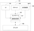
図1は、本発明における画像処理システムとしてのMFP101の構成を示す図である。同図に示すように本実施形態のMFP101は、UI102、スキャナ103、記憶装置104、コントローラ105、プリンタ106から構成される。コントローラ105は画像処理部107を有している。
System Configuration FIG. 1 is a diagram showing a configuration of the
UI102は、ユーザからの入力を受け付けるためのインタフェースであり、またユーザへの指示やMFP101の状態を示す表示装置でもある。スキャナ103はオートドキュメントフィーダー(ADF)を含むスキャナである。スキャナ103は、束状のあるいは一枚の原稿画像を図示しない光源で照射し、原稿反射像をレンズでCCDセンサ等の固体撮像素子上に結像し、固体撮像素子からラスター状の画像読み取り信号を画像データとして得る。記憶装置104は、コントローラ105で処理されたデータやコントローラ105が受け取ったデータの他、キャリブレーションの際に用いられるチャートデータや色変換テーブル等を保存する。コントローラ105と接続されたプリンタ106は、シアン(C),マゼンタ(M),イエロー(Y)の3色にブラック(K)を加えた計4色の有色トナーを用いて紙上に出力データを形成する出力デバイスである。プリンタ106は、記録用紙の給紙を行って出力データを形成した後にこれを排紙する。画像処理部107は、スキャナ103で読み込んだ画像等に対して画像処理を行う。
The
●画像処理概要
図14に、画像処理部107における画像処理の流れを示す。画像処理部107は、データ受信部1401で受信したデータを判定する。受信したデータがスキャナ103から受信したスキャンデータ(RGB)であれば、そのスキャンデータをスキャンデータ色変換部1402へ送信する。一方、スキャンデータではない場合はラスターデータであるから、そのラスターデータ(R"G"B")を色変換部1403に送信する。スキャンデータ色変換部1402では、スキャンデータ(RGBデータ)に対する色変換を行って、共通RGBデータ(R'G'B')に変換する。ここで共通RGBデータとは、デバイスに依存しないRGB色空間で定義されており、演算によってL*a*b*等のデバイス非依存色空間に変換することが可能なデータである。
Image Processing Overview FIG. 14 shows the flow of image processing in the
色変換部1403ではスキャンデータ色変換部1402またはデータ受信部1401から送られてきたデータ(R'G'B'またはR"G"B")に対する色変換を行う。受信したRGB色空間のデータはこの色変換により、出力デバイス(プリンタ106)に依存するCMYK色空間に変換されたCMYKデータとなる。次に4D-LUT処理部1404で、デバイス依存色空間上での4次元の色変換(CMYK→CMYK)を示すLUT(以下、4D-LUT)を用いた補正処理を行うことで、CMYKによる混色の色味を補正する。本実施形態におけるキャリブレーション処理としては、この4D-LUTを高精度に作成すること、および該4D-LUTの作成に用いられるチャートデータを生成することを特徴とする。4D-LUT処理部1404では、記憶装置104に対し3D-LUTデータやチャートデータなどのやり取りを行うが、その詳細については後述する。
The
4D-LUTを用いて混色の色味を補正した後、1D-LUT処理部1405で、1次元のLUT(以下、1D-LUT)を用いてC,M,Y,Kの各単色の階調特性を補正する。この1D-LUTの作成方法については周知の手法を用いることができるため、説明を省略する。そして1D-LUTを用いた階調補正の後、画像形成部1406で画像形成処理を行って、2値のCMYKデータ(CtMtYtKt)を作成する。最後に、データ送信部1407で2値のCMYKデータ(CtMtYtKt)をプリンタ106へ送信する。
After correcting the color mixture by using 4D-LUT, the 1D-
●基準情報の作成処理
本実施形態ではキャリブレーションを実行するに先立って、プリンタ106の色変換特性を示す基準情報、および該基準情報に対応するチャートデータ(基準チャートデータ)を予め作成し、記憶装置104に格納しておく。この基準情報としては複数を設定することが可能であり、キャリブレーションにおける補正目標としてそのいずれかがユーザによって選択される。
In this embodiment, prior to executing calibration, reference information indicating the color conversion characteristics of the
以下、基準情報の作成方法について、図15のフローチャートを用いて説明する。まずS1501にて、記憶装置104に予め保持されている、基準情報作成用のチャートデータに基づくチャート画像をプリンタ106より出力する。ここでのチャートデータは、CMYの各階調を均等の間隔で変化させたものであり、例えば全階調を8分割した場合は8×8×8=512個のデータとなる。このチャートデータによるチャート画像の例を図9に示す。図9において、用紙901上にチャートデータが有するデータ毎に一定の大きさの矩形902として表現し、この矩形902をパッチと称する。チャートデータが512個のパッチデータからなる場合は、チャート画像におけるパッチが512個となる。
Hereinafter, a method for creating reference information will be described with reference to the flowchart of FIG. First, in S1501, the
そしてS1502にて、チャート画像の測色値からL*a*b*値を取得する。次にS1503にて、上記基準情報作成用のチャートデータとL*a*b*値を用いて、デバイス依存色空間からデバイス非依存色空間へ、すなわちCMY→L*a*b*の3D-LUT(第1の色変換テーブル)を作成する。すなわちCMY→L*a*b*の3D-LUTは、チャート画像出力時のプリンタ106の状態に応じて作成される。
In S1502, the L * a * b * value is acquired from the colorimetric value of the chart image. Next, in S1503, using the chart data for creating the reference information and the L * a * b * value, the device-dependent color space is changed to the device-independent color space, that is, the CMY → L * a * b * 3D- Create a LUT (first color conversion table). That is, the 3D-LUT of CMY → L * a * b * is created according to the state of the
続いて、デバイス非依存色空間からデバイス依存色空間へ、すなわちL*a*b*→CMYの3D-LUT(第2の色変換テーブル)を作成する。まずS1504にて、RGB均等データとRGB色空間の頂点のCMY値を用いて、既存の補間演算によりRGB→CMYのLUTを作成する。RGB色空間においてR,G,B,C,M,Y,Bk,Wの各頂点が存在する。例えば、Rの頂点に対応するCMY値は(C,M,Y)=(0,255,255)となる。対応するCMY値はプリンタ106の特性に依存するため、必ずしも同じ値になるとは限らないが、例えばRGBCMYは最も彩度が高くなる組み合わせを、Bkは最も明度が低くなる組み合わせを選択する。ここで、CMY値の組み合わせはどのようなものであってもよい。そしてS1505にて、RGB→CMYとCMY→L*a*b*の3D-LUTを用いて、RGB→L*a*b*の3D-LUTを算出する。次にS1506にて、RGB→L*a*b*の3D-LUTから周知の演算手法による逆算を行い、L*a*b*→RGBの3D-LUTを作成する。そしてS1507にて、L*a*b*→RGBとRGB→CMYの3D-LUTを用いて、L*a*b*→CMYの3D-LUT(第2の色変換テーブル)を作成する。
Subsequently, a 3D-LUT (second color conversion table) of L * a * b * → CMY is created from the device-independent color space to the device-dependent color space. First, in S1504, an RGB → CMY LUT is created by an existing interpolation operation using the RGB uniform data and the CMY value of the vertex of the RGB color space. There are R, G, B, C, M, Y, Bk, and W vertices in the RGB color space. For example, the CMY value corresponding to the vertex of R is (C, M, Y) = (0,255,255). Since the corresponding CMY values depend on the characteristics of the
以上のように基準情報として作成された第1および第2の色変換テーブル、すなわちCMY→L*a*b*とL*a*b*→CMYの2つの3D-LUTは、その作成時におけるプリンタ106の色変換特性を示す情報として記憶装置104に保持される。そしてこの基準情報(3D-LUT)は、後述する4D-LUT作成の際に補正目標として利用される。
As described above, the first and second color conversion tables created as reference information, that is, two 3D-LUTs of CMY → L * a * b * and L * a * b * → CMY Information indicating the color conversion characteristics of the
●基準チャートデータの作成処理
本実施形態では、上述したように基準情報として作成された第1および第2の色変換テーブル、すなわちCMY→L*a*b*とL*a*b*→CMYの2つの3D-LUTについて、対応する基準チャートデータを作成して記憶装置104に格納する。この基準チャートデータにおけるL*a*b*値が、初回キャリブレーション時に基準値として参照される。
In this embodiment, as described above, the first and second color conversion tables created as reference information, that is, CMY → L * a * b * and L * a * b * → CMY For the two 3D-LUTs, corresponding reference chart data is created and stored in the
以下、この基準チャートデータの作成方法について、図16のフローチャートを用いて説明する。まずS1601において、L*a*b*色空間上で任意に定義された第1のL*a*b*データに対し、基準情報であるL*a*b*→CMYの3D-LUTを用いてパッチデータを作成する。ここで第1のL*a*b*データは、L*a*b*の膨大な組み合わせの中から任意数を定義したデータにおける1データであり、例えばL*a*b*色空間を一定の間隔で区切った均等データにおける1データである。 Hereinafter, a method for creating the reference chart data will be described with reference to the flowchart of FIG. First, in S1601, for the first L * a * b * data arbitrarily defined in the L * a * b * color space, the reference information L * a * b * → CMY 3D-LUT is used. To create patch data. Here, the first L * a * b * data is one data in an arbitrary number of data defined from a huge number of combinations of L * a * b *. For example, the L * a * b * color space is constant. It is one data in the uniform data divided by the interval.
次にS1602〜S1604において、上記S1601で処理された第1のL*a*b*データとそれに対するパッチデータ、および基準情報であるCMY→L*a*b*の3D-LUTを用いて、色域内判定を行う。ここで色域内判定とは、S1601で処理された第1のL*a*b*データ、すなわちパッチデータに対応する第1のL*a*b*データが、キャリブレーション対象であるプリンタ106の色再現範囲(色域)内にあるか否かを判定する処理である。ここで第1のL*a*b*データの中には、プリンタ106の色域の外側にあって、プリンタ106で出力できない色を示すものが存在する可能性がある。そのような色域外のL*a*b*データはキャリブレーションに利用することはできないため、本実施形態では該色域外のデータを除外するために、S1602〜S1604で色域内判定を行う。
Next, in S1602 to S1604, using the first L * a * b * data processed in S1601 and the corresponding patch data, and the 3D-LUT of CMY → L * a * b * which is the reference information, Perform in-gamut determination. Here, in-gamut determination refers to the first L * a * b * data processed in S1601, that is, the first L * a * b * data corresponding to the patch data of the
ここで、本実施形態における色域内判定処理について説明する。なお、色域判定の手法はこの例に限らず、第1のL*a*b*データがプリンタ106の色域内であるか否かを判定できれば、どのような手法を用いても良い。まずS1602にて、CMYのパッチデータに対し、CMY→L*a*b*の3D-LUTを用いて第2のL*a*b*データを算出する。
Here, the in-gamut determination process in the present embodiment will be described. Note that the color gamut determination method is not limited to this example, and any method may be used as long as it can be determined whether or not the first L * a * b * data is within the color gamut of the
ここで、L*a*b*色空間上で任意に作成した第1のL*a*b*データのうち、プリンタ106の色域外にあるデータは、S1601でL*a*b*→CMYの3D-LUTを用いてCMY値に変換された際に、色域内に収まる値にまるめられている。したがって、色域内にまるめられたCMY値(パッチデータ)をCMY→L*a*b*の3D-LUTを用いて第2のL*a*b*データに変換すると、該変換後の第2のL*a*b*データと変換前の第1のL*a*b*データとの間に大きな差が生じる。そこで本実施形態では色域内判定を行うために、S1603において第1のL*a*b*データと第2のL*a*b*データとの差分を算出し、S1604で該差分が所定の閾値内にあるか否かを判定する。すなわち、該差分が閾値内であれば第1のL*a*b*データはプリンタ106の色域内であると判定し、S1605で第1のL*a*b*データに対応するパッチデータを基準チャートデータに設定してS1606へ進む。一方、差分が閾値外であれば、パッチデータを基準チャートデータに設定することなく、S1606へ進む。
Here, among the first L * a * b * data arbitrarily created in the L * a * b * color space, the data outside the color gamut of the
そしてS1606において、L*a*b*色空間上で任意に設定された第1のL*a*b*データの全てについて、上記S1601〜S1605の処理が終了したか否かを判定し、全ての処理が終了していれば基準チャートデータの作成処理を終了する。一方、未終了であればS1601に戻って、未処理である第1のL*a*b*データについての処理を繰り返す。 In S1606, it is determined whether or not the processing of S1601 to S1605 has been completed for all of the first L * a * b * data arbitrarily set in the L * a * b * color space. If the above process is completed, the process for creating the reference chart data is terminated. On the other hand, if not completed, the process returns to S1601, and the process for the unprocessed first L * a * b * data is repeated.
このように基準チャートデータは、任意に作成したL*a*b*データからプリンタ106の色域外にあるL*a*b*データを除外して該色域内のL*a*b*データのみを抽出し、該抽出されたL*a*b*データのみを用いて作成される。この抽出には基準情報(CMY→L*a*b*の3D-LUT,L*a*b*→CMYの3D-LUT)が用いられるため、基準情報に応じた基準チャートが作成されることになる。このように、プリンタ106の色域内判定を行ってL*a*b*データの数を制限することで、基準チャート画像におけるパッチ数を減らすことが可能となる。作成された基準チャートデータは、その作成に用いられた基準情報と関連付けて記憶装置104に格納される。
In this way, the standard chart data excludes L * a * b * data outside the
●キャリブレーション処理
以下、本実施形態におけるキャリブレーション処理について説明する。本実施形態のキャリブレーション処理はすなわち、コントローラ105において4D-LUTを高精度に作成する処理であるが、まずその概要について図2のフローチャートを用いて説明する。
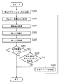
Calibration process Hereinafter, the calibration process in the present embodiment will be described. That is, the calibration process of the present embodiment is a process of creating a 4D-LUT with high accuracy in the
まずS201にてコントローラ105は、UI102からのキャリブレーション指示を受け取る。そしてS202にて、まずは初回のキャリブレーションを行うために、記憶装置104に予め保持されている基準チャートデータを読み込んで画像処理部107で処理した後、プリンタ106へ送信してチャート画像を出力する。この初回キャリブレーション用の基準チャートデータは、記憶装置104に保持されている複数の基準チャートデータのうち、ユーザによって補正目標として設定された基準情報に対応するものが選択され、読み込まれる。
First, in S201, the
次にS203にてスキャナ103を用いて、該出力したチャート画像の測色を行い、その測色値を得る。そしてS204にて該測色値を用いて、記憶装置104に基準情報として保持されている、デバイス非依存色空間からデバイス依存色空間への3次元の色変換(L*a*b*→CMY)を示す3D-LUTの補正を行う。この3D-LUTの補正処理は画像処理部107において行われるが、その詳細については後述する。そしてS205にて、該補正された3D-LUTに基づき、画像処理部107の4D-LUT処理部1404において使用される4D-LUTの作成を行う。この4D-LUTの作成処理は画像処理部107において行われるが、その詳細については後述する。
In step S203, the
4D-LUTの作成が終了すると、キャリブレーション終了判定を行う。すなわち、まずS206にて、ユーザによって階調性重視モードがオン設定されているか否かの判定を行う。階調性重視モードがオン設定でない場合(NOの場合)は処理を終了する。階調性重視モードがオン設定である場合(YESの場合)はS207にて、S204の3D-LUT補正処理において、その大きさが閾値を越えるために処理対象から除外された差分ベクトルがあるか否かを判定する。ここで差分ベクトルとは、チャートデータにおけるL*a*b*値(基準値)とそれを測色したL*a*b*値(測色値)との差分として算出されるものであるが、その詳細については後述する。除外された差分ベクトルがなければキャリブレーション処理を終了するが、ある場合にはS208に進み、該除外された差分ベクトルを用いて新たなチャートデータを作成する。そしてS202に戻って該新たなチャートデータに基づくチャート画像の出力指示を行い、2回目以降のキャリブレーション処理を繰り返す。なお、S208における新たなチャートデータ作成処理の詳細については後述する。 When the 4D-LUT creation is completed, the calibration end determination is performed. That is, first in S206, it is determined whether or not the tone-oriented mode is set to ON by the user. If the tone emphasis mode is not set to ON (NO), the process ends. When the gradation priority mode is set to ON (in the case of YES), in S207, in the 3D-LUT correction process of S204, is there a difference vector that is excluded from the processing target because its size exceeds the threshold value? Determine whether or not. Here, the difference vector is calculated as the difference between the L * a * b * value (reference value) in the chart data and the L * a * b * value (colorimetric value) obtained by colorimetric measurement. The details will be described later. If there is no excluded difference vector, the calibration process ends. If there is, the process proceeds to S208, and new chart data is created using the excluded difference vector. Then, returning to S202, an instruction to output a chart image based on the new chart data is given, and the second and subsequent calibration processes are repeated. Details of the new chart data creation process in S208 will be described later.
●3D-LUT補正処理(S204)
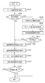
以下、上記S204におけるL*a*b*→CMYの3D-LUT補正処理について、図3のフローチャートを用いて詳細に説明する。なお補正対象であるL*a*b*→CMYの3D-LUTは、記憶装置104に基準情報として予め保持されている。
● 3D-LUT correction processing (S204)
Hereinafter, the L * a * b * → CMY 3D-LUT correction processing in S204 will be described in detail with reference to the flowchart of FIG. Note that the LD * a * b * → CMY 3D-LUT to be corrected is stored in advance in the
画像処理部107はまずS301にて、S202で出力されたチャート画像に対応する基準値と測色値の読み込みを行う。ここで基準値とは、該チャート画像に対応するチャートデータのL*a*b*値であるため、例えば初回キャリブレーション時であれば記憶装置104から基準チャートデータのL*a*b*値を読み込む。また2回目以降のキャリブレーション時には、上記S209にて新たに作成されたチャートデータのL*a*b*値を読み込む。また測色値は、該チャート画像をスキャナ103にて読み取ることによって得られるL*a*b*値である。
In step S301, the
次にS302にて、全ての基準値と測色値に対して白色点補正を行う。ここで白色点補正は、紙種の違いなどによる白色のずれを補正するものであり、紙の違いによる色(測色値)の差を吸収することができる。具体的には、紙白(記録用紙においてトナーの載っていない白部分)の測色値と、任意に定めた白の基準値(例えばCIEの定める標準光源D50下での白色としてのL=100,a=0,b=0)との比をとる。そしてその比を測色値や基準値に加味することで、白色点補正が行われる。 In step S302, white point correction is performed on all reference values and colorimetric values. Here, the white point correction is to correct a white shift due to a difference in paper type, and can absorb a difference in color (colorimetric value) due to a difference in paper. Specifically, the colorimetric value of paper white (the white portion on which the toner is not placed on the recording paper) and an arbitrarily defined white reference value (for example, L = 100 as white under the standard light source D50 defined by CIE) , a = 0, b = 0). The white point correction is performed by adding the ratio to the colorimetric value and the reference value.
そしてS303にて、3D-LUT補正の回数が2回目以降であるか否か、すなわち2回目以降のキャリブレーションであるか否かを判定する。3D-LUT補正回数が1回目である場合(NOの場合)には、S304にて白色点補正後の基準値の全てについて、対応する白色点補正後の測色値との差分を示す差分ベクトルを算出した後、S305に進む。一方、3D-LUT補正回数が2回目以降である場合(YESの場合)はS311に進み、前回選別された差分ベクトル(前回のS305,詳細は後述する)を読み込む。前回選別された差分ベクトルは、例えばコントローラ105内の不図示のメモリに保持されている。そしてS312にて、S301で読み込まれた基準値のうち、前回処理時とは異なる新たな基準値について、対応する測色値との差分ベクトルを算出し、これを新規の差分ベクトルとして、S311で読み込んだ差分ベクトルに追加した後、S305に進む。
In step S303, it is determined whether or not the number of 3D-LUT corrections is the second or later, that is, whether or not the second or later calibration is performed. When the number of 3D-LUT corrections is the first time (in the case of NO), a difference vector indicating the difference from the corresponding colorimetric values after white point correction for all the reference values after white point correction in S304 After calculating, the process proceeds to S305. On the other hand, if the 3D-LUT correction count is the second or later (YES), the process proceeds to S311 and the previously selected difference vector (last S305, details will be described later) is read. The previously selected difference vector is held in a memory (not shown) in the
S305では、差分ベクトルの選別処理を行う。この選別処理は、各差分ベクトルについて、その大きさが任意の閾値を超えているものを全体から突出した差分ベクトルとみなし、後述する補正量の算出処理(S306〜S308)時に参照する差分ベクトルから除外することによって行われる。例えば閾値を、L*a*b*→CMYの3D-LUTにおけるL*a*b*空間内の格子点間距離とすれば、該格子点間距離を越える大きさの差分ベクトルがあれば除外フラグを立てて、補正量算出時に演算対象から外すようにする。これにより、デバイスの触れや個体ばらつきのほか、チャートデータが不適切であることによって発生する、階調性の維持が困難な色に対応する差分ベクトルを演算対象から外して、キャリブレーションを行うことができる。S305における選別結果は、例えばコントローラ105内の不図示のメモリに保持される。
In S305, a difference vector selection process is performed. In this selection process, for each difference vector, the one whose magnitude exceeds an arbitrary threshold is regarded as a difference vector protruding from the whole, and from the difference vector referred to during correction amount calculation processing (S306 to S308) described later. Done by excluding. For example, if the threshold is the distance between lattice points in the L * a * b * space in the L * a * b * → CMY 3D-LUT, any difference vector that exceeds the distance between the lattice points is excluded. A flag is set so that it is excluded from the calculation target when calculating the correction amount. In this way, calibration is performed by excluding the difference vector corresponding to the color that is difficult to maintain the gradation, which occurs due to inappropriateness of the chart data, in addition to the touch of the device and individual variations. Can do. The selection result in S305 is held in a memory (not shown) in the
次に、選別された差分ベクトルを用いて、S306〜S310で3D-LUTの各格子点の出力値を補正するテーブル補正処理を行う。まずS306にて、L*a*b*→CMYの3D-LUTの格子点データと、白色点補正後の、差分ベクトルの基準値との距離算出を行い、S307にて該距離が所定の閾値(第4の閾値)以内となる差分ベクトルを探索し、抽出する。この抽出は、例えばL*a*b*空間内において、注目する格子点を中心とし、格子点間距離を半径とする球内に、差分ベクトルがあるかを探索することによって行う。具体的には、注目格子点と差分ベクトルの基準値間との距離が、該半径よりも小さいものを抽出していく。球内に差分ベクトルがなければ半径を倍にして未探索の球内を探索する。例えば、閾値を4格子点間の距離とした場合であれば探索を3回繰り返し、差分ベクトルがなければ処理を終了する。 Next, using the selected difference vector, table correction processing for correcting the output value of each lattice point of the 3D-LUT is performed in S306 to S310. First, in S306, the distance between the L * a * b * → CMY 3D-LUT grid point data and the reference value of the difference vector after white point correction is calculated. In S307, the distance is a predetermined threshold value. A difference vector within (fourth threshold) is searched and extracted. This extraction is performed, for example, by searching for a difference vector in a sphere centered on the lattice point of interest and having a radius between the lattice points in the L * a * b * space. Specifically, the distance between the target lattice point and the reference value of the difference vector is smaller than the radius. If there is no difference vector in the sphere, the radius is doubled and an unsearched sphere is searched. For example, if the threshold is a distance between four grid points, the search is repeated three times, and if there is no difference vector, the process ends.
次にS308にて、抽出された差分ベクトルから、L*a*b*→CMYの3D-LUTの格子点データに対する補正量を決定する。抽出された差分ベクトルが1つである場合は、その差分ベクトルがそのまま補正量となる。一方、複数個の差分ベクトルが抽出される可能性があり、その中でも格子点データに対して距離が近いもの、遠いものが存在する。本実施形態では、距離が近い差分ベクトルの影響を強くし、距離が遠い差分ベクトルの影響を弱くするために、複数個の差分ベクトルに対し、それぞれに算出された距離に応じた重み付き加算を行って、格子点補正量を決定する。重みは、例えば以下の式(1)のように決定する。なお式(1)において、Wは重み、Dは格子点と基準値間の距離、Kwは重み係数、Offsetはオフセットである。 Next, in S308, a correction amount for L * a * b * → CMY 3D-LUT lattice point data is determined from the extracted difference vector. When there is one extracted difference vector, the difference vector is directly used as the correction amount. On the other hand, there is a possibility that a plurality of difference vectors are extracted, and among them, there are those having a short distance and those far from the grid point data. In this embodiment, in order to increase the influence of the difference vector having a short distance and weaken the influence of the difference vector having a long distance, a weighted addition corresponding to each calculated distance is performed on a plurality of difference vectors. Go to determine the grid point correction amount. The weight is determined, for example, as in the following formula (1). In Equation (1), W is a weight, D is a distance between a grid point and a reference value, Kw is a weighting factor, and Offset is an offset.
W=1/(DKw)+Offset ・・・(1)
このように重みを求め、「差分ベクトル×重み」を、処理対象である複数個の差分ベクトルにそれぞれ対応する重みの合計値で除算して正規化する。これにより、距離に応じた重み付け差分ベクトルに基づく格子点補正量が算出され、距離が遠いほど該補正量が小さくなる。なお、重み係数及びオフセットにより、距離に応じた重みの変化量を制御することが可能である。なお、閾値以内に差分ベクトルが存在しない場合には、当該格子点データに対する補正量は0となる。
W = 1 / (D Kw ) + Offset (1)
Weights are obtained in this way, and “difference vector × weight” is normalized by dividing by the total weight value corresponding to each of the plurality of difference vectors to be processed. As a result, the lattice point correction amount based on the weighted difference vector corresponding to the distance is calculated, and the correction amount decreases as the distance increases. Note that the amount of change in weight according to the distance can be controlled by the weight coefficient and the offset. If there is no difference vector within the threshold value, the correction amount for the grid point data is zero.
以上のように格子点補正量が決定されると、次にS309にて、該格子点補正量を格子点データに反映する。S308で求めた補正量は、L,a,bのそれぞれに対応する3つの値を持っている。その各値は格子点のL,a,b各値をどれくらいずらすべきかを示しているため、格子点のL,a,b各値に、対応する補正量(L,a,b各値)を加算することで補正量を反映し、該加算値を補正後格子点データとする。 When the lattice point correction amount is determined as described above, in S309, the lattice point correction amount is reflected in the lattice point data. The correction amount obtained in S308 has three values corresponding to L, a, and b, respectively. Since each value indicates how much the L, a, and b values of the grid points should be shifted, the corresponding correction amount (L, a, b values) for each of the L, a, and b values of the grid points Is added to reflect the correction amount, and the added value is used as corrected lattice point data.
以上S306〜S309による格子点補正処理を3D-LUTの全ての格子点について行った後、S310にて、補正後格子点データに対してL*a*b*→CMYの3D-LUTを用いた補間演算を行って、新しいCMY値を算出する。このCMY値を元々の格子点データに対する出力値として格納することで、L*a*b*→CMYの3D-LUT(補正後)を作成する。 After performing the grid point correction processing in S306 to S309 for all grid points of the 3D-LUT, in S310, L * a * b * → CMY 3D-LUT was used for the corrected grid point data. Interpolation is performed to calculate a new CMY value. By storing this CMY value as an output value for the original lattice point data, an L * a * b * → CMY 3D-LUT (after correction) is created.
なお、L*a*b*→CMYの3D-LUT補正処理はこの例に限らず、どのような手法を用いても良い。例えばS309において、S308で算出した格子点補正量をそのまま格子点補正に反映させずに、該補正量の大きさを判定し、所定の閾値内である補正量のみを補正に反映させるようにしても良い。 Note that the L * a * b * → CMY 3D-LUT correction processing is not limited to this example, and any method may be used. For example, in S309, without correcting the grid point correction amount calculated in S308 to the grid point correction as it is, the magnitude of the correction amount is determined, and only the correction amount within a predetermined threshold is reflected in the correction. Also good.
●4D-LUT作成処理(S205)
以下、S205における4D-LUTのテーブル作成処理について、図4のフローチャートを用いて詳細に説明する。まずS401にて画像処理部107は、CMYK値を均等割することで予め作成されているCMYK均等データから、1つのCMY値を抽出する。ここでCMYK均等データとしては、作成するCMYK→CMYKの4D-LUTの格子点と同じ数のCMY値からなり、そのデータの間隔も格子点と同じである。例えば、CMYK→CMYKの4D-LUTの格子点数が8×8×8×8=4096個である場合は、CMYK均等データのデータ数も4096個となる。また、データが8ビット(0〜255)で表現される場合は、データの間隔は約36となる。
● 4D-LUT creation processing (S205)
Hereinafter, the 4D-LUT table creation processing in S205 will be described in detail with reference to the flowchart of FIG. First, in S401, the
次にS402にて、S401で抽出されたCMY値に対し、基準情報であるCMY→L*a*b*の3D-LUTとL*a*b*→CMYの3D-LUT(補正後)を用いた補間演算を行って、補正後CMY値を決定する。なお、ここで得られるCMY→CMYの3D-LUTを、本実施形態の作成目的である図14の4D-LUT処理部1404の4D-LUTに代えて用いることも可能である。
Next, in S402, CMY → L * a * b * 3D-LUT and L * a * b * → CMY 3D-LUT (after correction), which are the reference information, for the CMY values extracted in S401 The corrected CMY value is determined by performing the interpolation calculation used. Note that the CMY → CMY 3D-LUT obtained here can be used in place of the 4D-LUT of the 4D-
次にS403にて、CMYK均等データから、S401で抽出されたCMY値に対応するKの値を抽出し、S402で決定された補正後CMY値に組み合わせてCMYK値を作成する。そしてS404にて、デバイス情報を用いてトナー(記録剤)の載り量制限を行う。ここでデバイス情報とは、プリンタ106に適用可能なトナー量を数値で表現したものであり、以下、「載り量」と称する。例えばCMYKの場合、単色の載り量の最大値を100%とすると最大で400%の信号値が設定できる。しかし、適用可能なトナーの総量が300%の場合、最大載り量は300%となる。CMYK値は、その組み合わせによっては規定の載り量を超えてしまう可能性がある。したがってこのような場合、CMYのトナーをKのトナーに置き換えるUCR処理等を行うことで、トナーの全体量を許容量以下に抑制する載り量制限を行う。一般に黒を表現する場合、CMYを等量用いて表現する手法と、K単独で表現する手法が存在する。K単独で表現した場合、CMYで表現する場合に比べて濃度が低くなってしまうが、載り量を少なくできるというメリットがある。
Next, in S403, K values corresponding to the CMY values extracted in S401 are extracted from the CMYK uniform data, and combined with the corrected CMY values determined in S402 to create CMYK values. In step S404, the amount of applied toner (recording agent) is limited using the device information. Here, the device information represents a toner amount applicable to the
そしてS405にて純色化処理を行って、CMYK値(補正後)を作成する。ここで純色とは、CMYKまたはRGBWの各単色として表現される色であり、CMYK→CMYKの4D-LUTによる補正を行う際に、例えば入力値がC単色の純色データであれば、その出力値もC単色となることが理想である。したがって本実施形態では、オリジナルのCMYK均等データを参照して、処理対象データが元々は純色データであった場合には、S404による載り量制限後のCMYK値を純色データに修正する。例えば、CMYK均等データがC単色であったのに、載り量制限後のCMYK値にMの値が入っている場合には、このMの値を0にして、CMYK値(補正後)を生成する。そしてS406にて、CMYK均等データに対応するCMYK値(補正後)を、CMYK→CMYKの4D-LUTに格納する。 In step S405, pure color processing is performed to create a CMYK value (after correction). Here, the pure color is a color expressed as each single color of CMYK or RGBW, and when the correction is performed by 4D-LUT from CMYK to CMYK, for example, if the input value is pure color data of C single color, its output value Ideally, it should be C single color. Therefore, in this embodiment, referring to the original CMYK uniform data, if the processing target data is originally pure color data, the CMYK value after the applied amount restriction in S404 is corrected to pure color data. For example, if the CMYK uniform data is C single color but the M value is included in the CMYK value after the load limit, this M value is set to 0 and the CMYK value (after correction) is generated. To do. In S406, the CMYK value (after correction) corresponding to the CMYK uniform data is stored in the 4D-LUT of CMYK → CMYK.
なお、本実施形態ではLUTの格子点の数について具体的な数を挙げて説明を行ったが、、格子点数はもちろんこの例に限定されない。格子点数としてはさらに、CMYK→CMYKの4D-LUTにおいてCとMの格子点数が異なるなど、特殊な構成のLUTを構成しても良い。 In this embodiment, the number of LUT lattice points has been described with a specific number. However, the number of lattice points is not limited to this example. As the number of grid points, a LUT having a special configuration may be configured such that the number of grid points of C and M is different in a 4D-LUT from CMYK to CMYK.
●チャートデータ作成処理(S209)
以下、上記S209における新たなチャートデータの作成処理について、図5のフローチャートを用いて詳細に説明する。なお、図5に示す処理はS305で除外された差分ベクトルごとに行われる。
● Chart data creation process (S209)
Hereinafter, the process of creating new chart data in S209 will be described in detail with reference to the flowchart of FIG. The process shown in FIG. 5 is performed for each difference vector excluded in S305.
まずS501にて、除外された差分ベクトルに対応する基準値取得を行う。次にS502にて、該取得した基準値の周囲に、除外されなかった差分ベクトルも含めて他の差分ベクトルがあるか探索する。この探索は、上記S307における差分ベクトル探索処理と同様に、具体的には抽出した基準値の周囲に他の差分ベクトルの基準値があるか探索することによって行う。他の差分ベクトルがある場合(YESの場合)にはS503にて、S501で抽出した基準値に一番近い基準値を抽出する。この探索は、全ての差分ベクトルを対象として行う。また、他の差分ベクトルがない場合(NOの場合)にはS507にて、S501で抽出した基準値に一番近い、L*a*b*→CMYの3D-LUTの格子点を抽出する。 First, in S501, a reference value corresponding to the excluded difference vector is acquired. Next, in S502, it is searched whether there are other difference vectors including the difference vectors that are not excluded around the acquired reference value. This search is performed by searching for a reference value of another difference vector specifically around the extracted reference value, similarly to the difference vector search process in S307. If there is another difference vector (YES), in S503, the reference value closest to the reference value extracted in S501 is extracted. This search is performed on all difference vectors. If there is no other difference vector (NO), in S507, the L * a * b * → CMY 3D-LUT lattice point closest to the reference value extracted in S501 is extracted.
そしてS504にて、S501で抽出した基準値と、S503で抽出した基準値またはS507で抽出した格子点とを結ぶ線分を二等分する点、すなわち中心点を算出する。この中心点算出は、L*a*b*色空間内において行う。例えば、S501で抽出した1つの基準値を(L,a,b)、S503で抽出した差分ベクトルの基準値を(L',a',b')とすると、その中心点は((L+L')/2,(a+a')/2,(b+b')/2)となる。なお、S503またはS507で複数の基準値または格子点が抽出された場合には、全ての点による中心点を算出すれば良い。 In S504, a point that bisects the line segment connecting the reference value extracted in S501 and the reference value extracted in S503 or the lattice point extracted in S507, that is, the center point is calculated. This center point calculation is performed in the L * a * b * color space. For example, if one reference value extracted in S501 is (L, a, b) and the reference value of the difference vector extracted in S503 is (L ', a', b '), the center point is ((L + L ′) / 2, (a + a ′) / 2, (b + b ′) / 2). If a plurality of reference values or grid points are extracted in S503 or S507, the center point of all the points may be calculated.
続いてS505にてパッチデータ算出処理を行う。すなわち、S504で算出した中心点に対するパッチデータを、L*a*b*→CMYの3D-LUT(補正後)を用いて算出する。最後にS506にてチャートデータ作成処理を行う。すなわち、S505で除外された差分ベクトルごとに算出されたパッチデータを順次配置していくことで、新たなチャートデータを作成する。作成された新たなチャートデータは、例えばコントローラ105の不図示のメモリに保持される。
Subsequently, patch data calculation processing is performed in S505. That is, the patch data for the center point calculated in S504 is calculated using a 3D-LUT (after correction) of L * a * b * → CMY. Finally, chart data creation processing is performed in S506. That is, new chart data is created by sequentially arranging the patch data calculated for each difference vector excluded in S505. The created new chart data is held in a memory (not shown) of the
以上の処理を、混色キャリブレーショ時に除外された差分ベクトルの全てについて行うことで、該除外された全ての差分ベクトルに対応するパッチデータをその周辺差分ベクトル(又は格子点)に応じて近似した、新たなチャートデータが作成される。この新たなチャートデータはすなわち、その時のプリンタ106の状態に応じたチャートデータであり、該チャートデータを用いたキャリブレーションを繰り返すことにより、より高精度な補正が可能となる。
By performing the above processing for all of the difference vectors excluded during the color mixture calibration, the patch data corresponding to all of the excluded difference vectors is approximated according to the peripheral difference vectors (or grid points), New chart data is created. That is, the new chart data is chart data corresponding to the state of the
なお、新たなチャートデータの作成処理はこの例に限らず、除外された差分ベクトルに基づく新たなパッチデータが作成されていれば良い。例えばL*a*b*色空間において、除外された差分ベクトルの基準値が、L*a*b*→CMYの3D-LUTの外部に位置する場合、該LUTの内部に位置するように、色の近い新たなパッチデータを作成することも考えられる。このように作成されたパッチデータからなる新たなチャートデータを用いたキャリブレーションを行った場合、さらなる階調性の向上が望める。 The process for creating new chart data is not limited to this example, and it is only necessary to create new patch data based on the excluded difference vector. For example, in the L * a * b * color space, when the reference value of the excluded difference vector is located outside the L * a * b * → CMY 3D-LUT, so that it is located inside the LUT, It is also possible to create new patch data with similar colors. When calibration is performed using new chart data composed of patch data created in this way, further improvement in gradation can be expected.
●UI遷移
最後に、ユーザからの指示を受け付けるためのUI102における表示画面の遷移について、図6のフローチャートを用いて説明する。このUI102は、MFP101におけるコントローラ105の制御に応じて表示される。
UI Transition Finally, the transition of the display screen in the
UI102はまずS601にて、モード選択画面を表示する。図7にモード選択画面の一例を示す。モード選択画面701の中には「基準情報作成」ボタン702と「色味補正パラメータ作成」ボタン703、「基準情報作成および色味補正パラメータ作成」ボタン704が表示されている。ユーザが処理内容を選択することで指示を受け取ることができる。
In step S601, the
次にS602にてコントローラ105は、プリンタ106における現在の色味特性を示す基準情報を作成するか否かを判定する。すなわち、モード選択画面においてユーザが「基準情報作成」ボタン702、または「基準情報作成および色味補正パラメータ作成」ボタン704を選択した場合、基準情報を作成する(YES)と判断し、上記図15に示した基準情報作成処理を開始する。
In step S <b> 602, the
以下、S608〜S610における、基準情報作成時のUI遷移について説明する。まずS608において、UI102に基準名入力画面を表示して、ユーザから基準名の入力を受け付ける。ここで基準情報とは上述したように、該基準情報作成処理を実行した時点の、プリンタ106における混色を含む色味特性を示す色変換情報である。具体的には、デバイス依存色空間からデバイス非依存色空間への対応関係を記述したL*a*b*→CMYのLUT(第1の色変換テーブル)と、その逆の対応関係を記述したCMY→L*a*b*のLUT(第2の色変換テーブル)である。この基準情報が4D-LUT(第3の色変換テーブル)作成時に参照される。基準情報には、ユーザによって基準名が付与されることによって、異なる時刻に作成された複数の基準情報を識別することができる。
Hereinafter, UI transitions at the time of creating reference information in S608 to S610 will be described. First, in S608, a reference name input screen is displayed on the
次にS609にて、基準情報を作成するために必要なチャート画像がプリンタ106から出力される旨の表示(出力画面表示)が行われる。該出力画面表示において例えばユーザが出力を了解したタイミングに応じて、プリンタ106がチャート画像(チャートA)を出力する。この出力が、上記図15におけるS1501のチャート画像出力処理に対応する。その後、S610で測色値取得画面を表示し、スキャナ103等を用いて、出力されたチャート画像の測色値を取得するようにユーザに促す。この測色値取得画面に応じて、上記図15におけるS1502の測色値取得処理が行われる。
Next, in S609, a display (output screen display) that a chart image necessary for creating reference information is output from the
そしてS611において、基準情報作成後に色味補正を行うか否かを判定する。すなわち、モード選択画面において「基準情報作成および色味補正パラメータ作成」ボタン704が選択されていれば、図2に示すキャリブレーションを行う(YES)と判定してS603に進む。一方、「基準情報作成」ボタン702が選択されていれば、キャリブレーションを行わない(NO)と判定して、処理を終了する。また、S602において「色味補正パラメータ作成」ボタン703が選択されていた場合には、基準情報を作成せずに(NO)キャリブレーションのみを行うと判定してS603へ進む。
In step S611, it is determined whether to perform color correction after the reference information is created. That is, if the “reference information creation and color correction parameter creation”
以下、S603以降の、キャリブレーション(図2)実行時のUI遷移について説明する。まずS603では、階調重視モード選択画面を表示して、階調性を重視した補正を行うか否かをユーザに選択させる。図13に、階調性重視モード選択画面の一例を示す。UI画面1301には、階調性を重視する旨を示す「YES」ボタン1302と、階調性を重視しない旨を示す「NO」ボタン1303が表示されている。ユーザによって「YES」ボタン1302が選択されると階調性重視モードがオンに設定され、「NO」ボタン1302が選択されると階調性重視モードがオフに設定される。ここで設定された階調性重視モードは、例えばコントローラ105内の不図示のメモリに保持される。
Hereinafter, the UI transition at the time of executing calibration (FIG. 2) after S603 will be described. First, in step S603, a gradation emphasis mode selection screen is displayed to allow the user to select whether or not to perform correction emphasizing gradation. FIG. 13 shows an example of the gradation priority mode selection screen. On the
次にS604にて基準情報選択画面を表示する。図8に基準情報選択画面の一例を示す。図8に示すようにUI画面801中に、選択対象となる基準情報の候補がリスト表示され、この中から1つのみを選択可能とする。ここで選択された基準情報に基づき、色味補正(キャリブレーション)が行われる。リスト内の表示名は、記憶装置104に保持されている基準情報に対応しており、この例では「デフォルト」802、「基準情報A」803、「基準情報B」804、「基準情報C」805がリスト表示される。「デフォルト」802は予め設定されているデフォルトの基準情報に対応しており、例えば開発時に用いられた理想値等、プリンタ106の代表値としての基準情報である。これが選択されることで、初回キャリブレーション時に代表値に基づいて作成された基準チャートが選択され(S202)、代表値が示す色味に近づくように色味補正が行われる。「デフォルト」802以外の「基準情報A」803、「基準情報B」804、「基準情報C」805はそれぞれ、上記図15に示したようにユーザ指示に応じて作成された基準情報に対応する。ユーザにより作成された基準情報が選択されることで、初回キャリブレーション時に該基準情報に基づいて作成された基準チャートが選択され(S202)、該基準情報の作成時点におけるプリンタ106の色味に近づくように色味補正が行われる。
In step S604, a reference information selection screen is displayed. FIG. 8 shows an example of the reference information selection screen. As shown in FIG. 8, a list of reference information candidates to be selected is displayed on the
リスト表示された基準情報から1つが選択された後に「次へ」ボタン806が押されると、次にS605にて、色味補正用のチャート画像がプリンタ106から出力される旨の表示(出力画面表示)が行われる。該出力画面表示において例えばユーザが出力を了解したタイミングに応じて、プリンタ106がチャート画像(チャートB)を出力する。この出力が、上記図2のS202で出力されるチャート画像に対応する。ここで出力されるチャート画像(チャートB)は、S604で選択された基準情報に対応するチャートデータに基づくものであり、基準情報作成時にS609で出力される、CMY色空間を均等分割したチャート画像(チャートA)とは異なる。その後、S606で測色値取得画面を表示し、スキャナ103等を用いて、出力されたチャート画像の測色値を取得するようにユーザに促す。この測色値取得画面に応じて、上記図2におけるS203の測色値取得処理が行われる。
When the “Next”
そして、キャリブレーション処理として4D-LUTの作成(S205)が終了した後、コントローラ15はS607にて、色味補正を終了するか否かを判定する。この判定は、上記図2のS206,S207に対応する。すなわち、上記S603で階調重視選択画面より階調性重視モードがオン設定されており、かつ上記S305で除外された差分ベクトルがある場合に、色味補正を継続すると判定し、それ以外の場合には処理を終了する。継続と判定された場合、上記図2のS209において、除外された差分ベクトルを用いた新たなチャートデータが作成されるため、UI102はS605に戻って、新たなチャート画像の出力画面表示を行う。
Then, after the creation of the 4D-LUT (S205) is completed as the calibration process, the controller 15 determines in S607 whether to end the color correction. This determination corresponds to S206 and S207 in FIG. That is, if the tone emphasis mode is set to ON from the tone emphasis selection screen in S603 and there is a difference vector excluded in S305, it is determined to continue the color correction, otherwise The process ends. If it is determined to continue, since new chart data using the excluded difference vector is created in S209 of FIG. 2 described above, the
新たなチャート画像を用いた再度のキャリブレーションを行う場合、前回のキャリブレーションによってL*a*b*→CMYの3D-LUTが既に補正されており、処理開始時点に選択した基準情報とは異なっている。したがって、キャリブレーションの実行ごとに、該時点での色味特性を示す基準情報を作成しておくことも有用である。すなわち、例えばS607で色味補正継続と判定された場合に、S608〜S610のUI表示を行って現時点での基準情報を作成し、記憶装置104に格納した後に、S605のチャート出力画面を表示しても良い。
When recalibrating with a new chart image, the L * a * b * → CMY 3D-LUT has already been corrected by the previous calibration and is different from the reference information selected at the start of processing. ing. Therefore, it is also useful to create reference information indicating the color characteristics at that time every time calibration is executed. That is, for example, when it is determined in S607 that the color correction is to be continued, the UI display of S608 to S610 is performed to create the current reference information, and the chart information screen of S605 is displayed after storing in the
以上説明したように本実施形態によれば、混色キャリブレーションにおいて用いられる差分ベクトルを選別し、それに対応した新たなチャートデータを用いてキャリブレーションを繰り返す。これにより、キャリブレーション精度(階調性等)を向上させることができる。 As described above, according to the present embodiment, the difference vector used in the color mixture calibration is selected, and the calibration is repeated using the new chart data corresponding thereto. Thereby, calibration accuracy (gradation etc.) can be improved.
<第2実施形態>
以下、本発明に係る第2実施形態について説明する。上述した第1実施形態では、S305における差分ベクトルの選別を、単純な閾値との比較によって行う例を示した。第2実施形態では、注目する差分ベクトルについて、その周囲の差分ベクトルとの比較による選別を行うことで、より高精度な選別を可能とする。なお、第2実施形態におけるシステム構成、およびキャリブレーションにおける差分ベクトル選別(S305)以外の処理は、上述した第1実施形態と同様である。したがって以下では、第2実施形態における差分ベクトル選別処理についてのみ、図10のフローチャートを用いて説明する。
Second Embodiment
Hereinafter, a second embodiment according to the present invention will be described. In the first embodiment described above, an example is shown in which the selection of the difference vector in S305 is performed by comparison with a simple threshold value. In the second embodiment, the difference vector of interest is selected by comparison with the surrounding difference vectors, thereby enabling more accurate selection. The system configuration in the second embodiment and the processes other than the difference vector selection (S305) in calibration are the same as those in the first embodiment described above. Therefore, only the difference vector selection process in the second embodiment will be described below using the flowchart of FIG.
まずS1001において画像処理部107は、注目する差分ベクトルを抽出し、さらに該差分ベクトルの周囲の差分ベクトル(周辺差分ベクトル)を探索して抽出する。ここで周辺差分ベクトルとは、L*a*b*色空間上で注目する差分ベクトルから所定範囲内において、該注目差分ベクトルに一番近いものから順に任意の数を抽出した差分ベクトルのことである。この探索方法については、上述した第1実施形態においてS307で用いた探索と同様であり、対応する基準値に基づいて行われる。
First, in step S1001, the
続いてS1002において第1の除外判定を行う。すなわち、注目差分ベクトルと周辺差分ベクトルとの大きさの比較を行い、その差分が所定の閾値(第2の閾値)を超えるものが比較数(周辺差分ベクトルの数)の半数を超えているか否かを判定する。該閾値を超える周辺差分ベクトルが半数以上である(YES)場合は、注目差分ベクトルが周辺差分ベクトルと比較してその大きさが突出しているとして、S1003でLUTの補正量算出時に参照する差分ベクトルから除外して、処理を終了する。 Subsequently, in S1002, a first exclusion determination is performed. That is, the difference between the target difference vector and the peripheral difference vector is compared, and whether the difference exceeds a predetermined threshold (second threshold) exceeds half of the number of comparisons (the number of peripheral difference vectors). Determine whether. If the number of peripheral difference vectors exceeding the threshold is more than half (YES), the difference vector referred to when calculating the correction amount of the LUT is determined in S1003, assuming that the difference vector of interest is protruding compared to the peripheral difference vector. And the process ends.
一方、S1002において該閾値を超える周辺差分ベクトルが半数以上でない(NO)場合は、S1004で第2の除外判定を行う。すなわち、L*a*b*色空間上において注目差分ベクトルと周辺差分ベクトルとのなす角度が所定の閾値(第3の閾値)を超えるものが比較数(周辺差分ベクトルの数)の半数を超えているか否かを判定する。この角度判定は、L*a*b*空間内であれば、L*-a*平面、L*-b*平面、a*-b*平面で順に行う。例えばL*-a*平面における角度は、注目差分ベクトルをL1、周辺差分ベクトルL2とすると、Arccos{<L1,L2>/|L1|×|L2|}により求まる。なお、<L1,L2>はL1,L2の内積、|L1|,|L2|はそれぞれL1,L2の長さである。各平面で角度判定を行い、少なくとも1つの平面において閾値を超えていれば、対応する周辺差分ベクトルについては、該閾値を超えたものと判定される。そして、角度が該閾値を超える周辺差分ベクトルが半数以上ある(YES)場合は、注目差分ベクトルが周辺差分ベクトルと比較してその向きが突出しているとして、S1003でLUTの補正量算出時に参照する差分ベクトルから除外して、処理を終了する。一方、角度が該閾値を越える周辺差分ベクトルが半数以上でない(NO)場合は、そのまま処理を終了する。 On the other hand, if the peripheral difference vector exceeding the threshold value is not more than half (NO) in S1002, the second exclusion determination is performed in S1004. That is, in the L * a * b * color space, the angle between the target difference vector and the peripheral difference vector exceeds a predetermined threshold (third threshold) exceeds half of the number of comparisons (the number of peripheral difference vectors). It is determined whether or not. This angle determination is performed in order on the L * -a * plane, the L * -b * plane, and the a * -b * plane in the L * a * b * space. For example, the angle in the L * -a * plane can be obtained by Arccos {<L1, L2> / | L1 | × | L2 |} where the difference vector of interest is L1 and the peripheral difference vector L2. <L1, L2> is the inner product of L1 and L2, and | L1 | and | L2 | are the lengths of L1 and L2, respectively. An angle is determined on each plane, and if the threshold is exceeded on at least one plane, the corresponding peripheral difference vector is determined to have exceeded the threshold. If there are more than half of the peripheral difference vectors whose angles exceed the threshold (YES), it is referred to when calculating the correction amount of the LUT in S1003, assuming that the direction of the difference vector of interest is protruding compared to the peripheral difference vector. Excluding from the difference vector, the process is terminated. On the other hand, if the number of peripheral difference vectors whose angles exceed the threshold is not more than half (NO), the processing is terminated as it is.
なお、ここでは第1の除外判定(S1002)および第2の除外判定(S1004)における判定条件を、いずれも比較数の半数(50%)以上とする例を示したが、本発明はもちろんこの例に限定されない。例えば該判定条件を、第1の除外判定では第1の割合以上とし、第2の除外判定では第2の割合以上とすることができ、もちろん第1の割合と第2の割合は同じであっても良い。 In this example, the determination conditions in the first exclusion determination (S1002) and the second exclusion determination (S1004) are both set to half or more (50%) of the number of comparisons. It is not limited to examples. For example, the determination condition may be a first ratio or more in the first exclusion determination and a second ratio or more in the second exclusion determination. Of course, the first ratio and the second ratio are the same. May be.
以上説明したように第2実施形態によれば、差分ベクトルの選別の際にその周辺差分ベクトルを考慮することによって、処理量は増加するものの、より高精度な選別が可能となる。したがって、より階調性を重視するように3D-LUTを補正することができる。 As described above, according to the second embodiment, by considering the peripheral difference vector when selecting the difference vector, the processing amount increases, but more accurate selection is possible. Therefore, it is possible to correct the 3D-LUT so that the gradation is more important.
なお、第2実施形態を上述した第1実施形態に合成することも可能である。この場合例えば、まず大きさが第1の閾値以上である差分ベクトルについては無条件に除外し、大きさが第1の閾値以内である差分ベクトルについて、第2実施形態のように周辺差分ベクトルとの関係を考慮して、除外するか否かを判定すれば良い。 The second embodiment can be combined with the first embodiment described above. In this case, for example, first, a difference vector having a magnitude equal to or greater than the first threshold is unconditionally excluded, and a difference vector having a magnitude within the first threshold is used as a peripheral difference vector as in the second embodiment. It is sufficient to determine whether or not to exclude them in consideration of the relationship.
<第3実施形態>
以下、本発明に係る第3実施形態について説明する。上述した第1実施形態では、除外された差分ベクトルに基づいて新たなパッチデータを作成し、順次配列して新たなチャートデータを作成し、キャリブレーションを繰り返す例を示した。第3実施形態では、作成された新たなチャートデータを、次回のキャリブレーションのために保持しておくことを特徴とする。キャリブレーション時に作成された新たなチャートデータを、相当の期間をあけて次回のキャリブレーションに用いる等、その長期的な運用を想定した場合、新たなチャートデータのパッチ配列は元のチャートデータに近いほうが、より高精度な補正が行える。そこで第3実施形態では、新たに作成したパッチデータで、初回キャリブレーション用として予め記憶装置104に保持されている、基準チャートデータにおけるパッチデータを置き換えることを特徴とする。なお、第3実施形態におけるシステム構成、およびチャートデータ作成(S506)以外の処理は、上述した第1または第2実施形態と同様である。したがって以下では、第3実施形態におけるチャートデータ作成処理についてのみ、図11のフローチャートを用いて説明する。
<Third Embodiment>
The third embodiment according to the present invention will be described below. In the first embodiment described above, an example has been shown in which new patch data is created based on the excluded difference vector, sequentially arranged to create new chart data, and calibration is repeated. The third embodiment is characterized in that the created new chart data is retained for the next calibration. If the new chart data created at the time of calibration is used for the next calibration after a considerable period of time, the patch arrangement of the new chart data is close to the original chart data. The correction can be performed with higher accuracy. Therefore, the third embodiment is characterized in that the patch data in the reference chart data, which is stored in advance in the
まずS1101において画像処理部107は、S202で初回キャリブレーション時に記憶装置104から読み込まれたチャートデータから、除外された差分ベクトルに対応するパッチデータを抽出する。そしてS1102にて、該抽出したパッチデータを、除外された差分ベクトルに対してS505で算出された新たなパッチデータに置き換える。最後にS1103において、置き換えられたパッチデータ以外のパッチデータはそのままとして、新たなチャートデータを作成する。
First, in step S1101, the
ここで第3実施形態におけるUI102の表示画面の遷移について、図12のフローチャートを用いて、上述した第1実施形態とは異なる部分のみを説明する。図12においては、S607で色味補正を終了すると判定された場合に、S1212で新たなチャートデータを再利用するか否かをユーザに選択させるための新規チャート再利用選択画面を表示することを特徴とする。再利用する場合は、上述したように新たなパッチデータを反映して作成された新たなチャートデータを、デフォルトの基準情報に対応付けて記憶装置104に格納する。すなわち、デフォルトの基準チャートデータが、新たなチャートデータに置き換えられる。これにより次回のキャリブレーション実行時には、S604で図8に示す基準選択画面においてデフォルト802が選択された際に、該置き換えられた基準チャートデータが参照される。
Here, regarding the transition of the display screen of the
以上説明したように第3実施形態によれば、新たに作成されたパッチデータを、その際に用いられた基準チャートデータに反映させて、デフォルトに対応する基準チャートデータとして保持する。これにより、デフォルトに対応する基準チャートデータが、プリンタ106における直近の色味特性を示すものとして更新される。したがって、相当の期間をあけて次回のキャリブレーションを行う際に、該デフォルト対応の基準チャートデータを用いることにより、より効率的に、高精度なキャリブレーションを行うことができる。
As described above, according to the third embodiment, the newly created patch data is reflected in the reference chart data used at that time and held as reference chart data corresponding to the default. As a result, the reference chart data corresponding to the default is updated to indicate the latest color characteristic in the
<他の実施形態>
本発明は、以下の処理を実行することによっても実現される。即ち、上述した実施形態の機能を実現するソフトウェア(プログラム)を、ネットワーク又は各種記憶媒体を介してシステム或いは装置に供給し、そのシステム或いは装置のコンピュータ(またはCPUやMPU等)がプログラムを読み出して実行する処理である。
<Other embodiments>
The present invention is also realized by executing the following processing. That is, software (program) that realizes the functions of the above-described embodiments is supplied to a system or apparatus via a network or various storage media, and a computer (or CPU, MPU, or the like) of the system or apparatus reads the program. It is a process to be executed.
Claims (13)
前記チャートデータにおける各パッチデータの値である基準値と、該チャートデータにより前記出力デバイスが出力するチャート画像における各パッチの測色値、を取得する取得手段と、
前記基準値と対応する前記測色値との差分ベクトルのうち、前記第1の色変換テーブルの補正に用いる差分ベクトルを選別する選別手段と、
該選別された差分ベクトルを用いて前記第1の色変換テーブルの各格子点の出力値を補正するテーブル補正手段と、
前記第2の色変換テーブルおよび前記テーブル補正手段で補正された前記第1の色変換テーブルを用いて、前記出力デバイスによって出力される画像データを前記デバイス依存色空間上で補正する第3の色変換テーブルの格子点を表すデータを変換した結果を、該格子点の出力値に設定するテーブル作成手段と、
前記選別手段で選別されなかった差分ベクトルに対応する新たなパッチデータを、前記選別手段により選別されなかった差分ベクトルに対応する基準値に一番近い差分ベクトルまたは前記選別手段により選別されなかった差分ベクトルに対応する基準値に一番近い格子点、および前記テーブル補正手段で補正された前記第1の色変換テーブルを用いて算出して、新たなチャートデータを作成するチャートデータ作成手段と、を有し、
前記チャートデータ作成手段で作成された新たなチャートデータを用いて、再度、前記取得手段により基準値と測定値を取得し、前記テーブル補正手段により補正を行い、前記テーブル作成手段によりテーブル作成を行うことを特徴とする画像処理装置。 In the output device, a first color conversion table describing color conversion characteristics from a device-independent color space to a device-dependent color space, and color conversion characteristics from the device-dependent color space to the device-independent color space are described. A second color conversion table; and holding means for holding chart data composed of a plurality of patch data in the device-independent color space, created using the first and second color conversion tables;
An acquisition means for acquiring a reference value that is a value of each patch data in the chart data, and a colorimetric value of each patch in a chart image output from the output device by the chart data;
A selection means for selecting a difference vector used for correction of the first color conversion table among the difference vectors between the reference value and the corresponding colorimetric value;
Table correction means for correcting an output value of each grid point of the first color conversion table using the selected difference vector;
A third color for correcting the image data output by the output device on the device-dependent color space using the second color conversion table and the first color conversion table corrected by the table correction means. Table creation means for setting the result of converting the data representing the grid points of the conversion table to the output value of the grid points;
The new patch data corresponding to the difference vector that has not been selected by the selecting means is the difference vector closest to the reference value corresponding to the difference vector that has not been selected by the selecting means or the difference that has not been selected by the selecting means. Chart data creation means for creating new chart data by calculating using the grid point closest to the reference value corresponding to the vector and the first color conversion table corrected by the table correction means; Have
Using the new chart data created by the chart data creation means, the acquisition means again obtains a reference value and a measured value, corrects by the table correction means, and creates a table by the table creation means. An image processing apparatus.
前記注目差分ベクトルとの大きさの差が第2の閾値を越える前記周辺差分ベクトルの数が第1の割合以上となった場合に、該注目差分ベクトルを除外する第1の除外手段と、
前記注目差分ベクトルとのなす角度が第3の閾値を越える前記周辺差分ベクトルの数が第2の割合以上となった場合に、該注目差分ベクトルを除外する第2の除外手段と、を有し、
全ての前記差分ベクトルのうち、前記第1および第2の除外手段により除外されずに残った差分ベクトルを、前記第1の色変換テーブルの補正に用いる差分ベクトルとすることを特徴とする請求項1に記載の画像処理装置。 The selecting means searches for a difference vector within a predetermined range from the target difference vector in the device-independent color space for any target difference vector in the difference vector and extracts it as a peripheral difference vector. When,
First exclusion means for excluding the target difference vector when the number of the peripheral difference vectors whose magnitude difference from the target difference vector exceeds a second threshold is equal to or greater than a first ratio;
A second excluding unit that excludes the target difference vector when the number of the peripheral difference vectors exceeding a third threshold exceeds an angle formed by the target difference vector; ,
The difference vector that is not excluded by the first and second exclusion means among all the difference vectors is used as a difference vector used for correction of the first color conversion table. The image processing apparatus according to 1.
該距離が第4の閾値を超えない前記基準値に対応する前記差分ベクトルと、当該格子点を表すデータとの加算値を算出する加算手段と、
該加算値に対応する前記デバイス依存色空間の値を前記第1の色変換テーブルを用いて算出し、該算出された値を当該格子点の出力値とする補正手段と、
を有することを特徴とする請求項1乃至3のいずれか1項に記載の画像処理装置。 The table correction unit is a distance calculation unit that calculates a distance between each lattice point of the device-independent color space in the first color conversion table and the reference value corresponding to the difference vector;
Adding means for calculating an addition value of the difference vector corresponding to the reference value whose distance does not exceed a fourth threshold value and data representing the lattice point;
A correction unit that calculates a value of the device-dependent color space corresponding to the added value using the first color conversion table, and uses the calculated value as an output value of the grid point;
The image processing apparatus according to claim 1, further comprising:
全ての前記差分ベクトル、および前記第1の色変換テーブルの格子点のうち、前記基準値取得手段で取得した基準値に最も近い差分ベクトルまたは格子点を抽出する抽出手段と、
前記基準値取得手段で取得した前記基準値と、前記抽出手段で抽出された差分ベクトルに対応する前記基準値、または該抽出手段で抽出された前記格子点と、を結ぶ線分の中心点を算出する中心点算出手段と、
前記中心点に対応するパッチデータを、前記テーブル補正手段で補正された前記第1の色変換テーブルを用いて算出するパッチデータ算出手段と、
該算出されたパッチデータを前記基準値取得手段で取得した基準値ごとに配置して前記新たなチャートデータを作成するパッチデータの配置手段と、
を有することを特徴とする請求項1乃至4のいずれか1項に記載の画像処理装置。 The chart data creation means includes a reference value acquisition means for acquiring the reference value corresponding to the difference vector not selected by the selection means,
An extraction means for extracting a difference vector or a lattice point closest to the reference value acquired by the reference value acquisition means among all the difference vectors and the lattice points of the first color conversion table;
A center point of a line segment connecting the reference value acquired by the reference value acquisition means and the reference value corresponding to the difference vector extracted by the extraction means, or the grid point extracted by the extraction means. A center point calculating means for calculating;
Patch data calculation means for calculating patch data corresponding to the center point using the first color conversion table corrected by the table correction means;
Patch data placement means for creating the new chart data by placing the calculated patch data for each reference value acquired by the reference value acquisition means;
The image processing apparatus according to claim 1, further comprising:
前記チャートデータにおける各パッチデータの値である基準値と、該チャートデータにより前記出力デバイスが出力するチャート画像における各パッチの測色値を取得する取得手段と、
前記基準値と対応する前記測色値との差分ベクトルのうち、前記第1の色変換テーブルの補正に用いる差分ベクトルを選別する選別手段と、
該選別された差分ベクトルを用いて前記第1の色変換テーブルの各格子点の出力値を補正するテーブル補正手段と、
前記第2の色変換テーブルおよび前記テーブル補正手段で補正された前記第1の色変換テーブルを用いて、前記出力デバイスによって出力される画像データを前記デバイス依存色空間上で補正する第3の色変換テーブルの格子点を表すデータを変換した結果を、該格子点の出力値に設定するテーブル作成手段と、
を有し、
前記選別手段は、前記差分ベクトルのうち、その大きさが第1の閾値を超える差分ベクトルを除外した残りの差分ベクトルを、前記第1の色変換テーブルの補正に用いる差分ベクトルとすることを特徴とする画像処理装置。 In the output device, a first color conversion table describing color conversion characteristics from a device-independent color space to a device-dependent color space, and color conversion characteristics from the device-dependent color space to the device-independent color space are described. A second color conversion table; and holding means for holding chart data composed of a plurality of patch data in the device-independent color space, created using the first and second color conversion tables;
A reference value that is a value of each patch data in the chart data, and an acquisition unit that acquires a colorimetric value of each patch in a chart image output from the output device by the chart data;
A selection means for selecting a difference vector used for correction of the first color conversion table among the difference vectors between the reference value and the corresponding colorimetric value;
Table correction means for correcting an output value of each grid point of the first color conversion table using the selected difference vector;
A third color for correcting the image data output by the output device on the device-dependent color space using the second color conversion table and the first color conversion table corrected by the table correction means. Table creation means for setting the result of converting the data representing the grid points of the conversion table to the output value of the grid points;
Have
The selecting means uses, as difference vectors used for correction of the first color conversion table, remaining difference vectors excluding difference vectors whose magnitudes exceed a first threshold among the difference vectors. An image processing apparatus.
前記取得手段が、前記チャートデータにおける各パッチデータの値である基準値と、該チャートデータにより前記出力デバイスが出力するチャート画像における各パッチの測色値を取得し、
前記選別手段が、前記基準値と対応する前記測色値との差分ベクトルのうち、前記第1の色変換テーブルの補正に用いる差分ベクトルを選別し、
前記テーブル補正手段が、該選別された差分ベクトルを用いて前記第1の色変換テーブルの各格子点の出力値を補正し、
前記テーブル作成手段が、前記第2の色変換テーブルおよび前記テーブル補正手段で補正された前記第1の色変換テーブルを用いて、前記出力デバイスによって出力される画像データを前記デバイス依存色空間上で補正する第3の色変換テーブルの格子点を表すデータを変換した結果を、該格子点の出力値に設定し、
前記チャートデータ作成手段が、前記選別手段で選別されなかった差分ベクトルに対応する新たなパッチデータを、前記選別手段により選別されなかった差分ベクトルに対応する基準値に一番近い差分ベクトルまたは前記選別手段により選別されなかった差分ベクトルに対応する基準値に一番近い格子点、および前記テーブル補正手段で補正された前記第1の色変換テーブルを用いて算出して、新たなチャートデータを作成し、
前記チャートデータ作成手段で作成された新たなチャートデータを用いて、再度、前記取得手段が基準値と測定値を取得し、前記テーブル補正手段が補正を行い、前記テーブル作成手段がテーブル作成を行うことを特徴とする画像処理方法。 In the output device, a first color conversion table describing color conversion characteristics from a device-independent color space to a device-dependent color space, and color conversion characteristics from the device-dependent color space to the device-independent color space are described. Holding means and holding means for holding a second color conversion table, and chart data composed of a plurality of patch data in the device-independent color space, created using the first and second color conversion tables An image processing method in an image processing apparatus having a selection means, a table correction means, a table creation means, and a chart data creation means,
The acquisition means acquires a reference value that is a value of each patch data in the chart data, and a colorimetric value of each patch in the chart image output by the output device based on the chart data,
The selecting unit selects a difference vector used for correction of the first color conversion table from the difference vector between the reference value and the corresponding colorimetric value;
The table correction means corrects the output value of each grid point of the first color conversion table using the selected difference vector;
The table creation means uses the second color conversion table and the first color conversion table corrected by the table correction means to output image data output by the output device on the device-dependent color space. The result of converting the data representing the grid point of the third color conversion table to be corrected is set as the output value of the grid point,
The chart data creating means selects new patch data corresponding to the difference vector not selected by the selecting means, the difference vector closest to the reference value corresponding to the difference vector not selected by the selecting means, or the selection A new chart data is created by calculation using the grid point closest to the reference value corresponding to the difference vector not selected by the means and the first color conversion table corrected by the table correction means. ,
Using the new chart data created by the chart data creation means, the acquisition means again obtains the reference value and the measured value, the table correction means corrects, and the table creation means creates the table. An image processing method.
前記取得手段が、前記チャートデータにおける各パッチデータの値である基準値と、該チャートデータにより前記出力デバイスが出力するチャート画像における各パッチの測色値を取得し、
前記選別手段が、前記基準値と対応する前記測色値との差分ベクトルのうち、その大きさが第1の閾値を超える差分ベクトルを除外した残りの差分ベクトルを、前記第1の色変換テーブルの補正に用いる差分ベクトルとして選別し、
前記テーブル補正手段が、該選別された差分ベクトルを用いて前記第1の色変換テーブルの各格子点の出力値を補正し、
前記テーブル作成手段が、前記第2の色変換テーブルおよび前記テーブル補正手段で補正された前記第1の色変換テーブルを用いて、前記出力デバイスによって出力される画像データを前記デバイス依存色空間上で補正する第3の色変換テーブルの格子点を表すデータを変換した結果を、該格子点の出力値に設定することを特徴とする画像処理方法。 In the output device, a first color conversion table describing color conversion characteristics from a device-independent color space to a device-dependent color space, and color conversion characteristics from the device-dependent color space to the device-independent color space are described. Holding means and holding means for holding a second color conversion table, and chart data composed of a plurality of patch data in the device-independent color space, created using the first and second color conversion tables An image processing method in an image processing apparatus having a selection means, a table correction means, a table creation means, and a chart data creation means,
The acquisition means acquires a reference value that is a value of each patch data in the chart data, and a colorimetric value of each patch in the chart image output by the output device based on the chart data,
The selection unit uses the first color conversion table to calculate the remaining difference vectors excluding the difference vectors whose magnitudes exceed the first threshold among the difference vectors between the reference values and the corresponding colorimetric values. As a difference vector used to correct
The table correction means corrects the output value of each grid point of the first color conversion table using the selected difference vector;
The table creation means uses the second color conversion table and the first color conversion table corrected by the table correction means to output image data output by the output device on the device-dependent color space. An image processing method characterized in that a result of converting data representing a grid point in the third color conversion table to be corrected is set as an output value of the grid point.
Priority Applications (2)
| Application Number | Priority Date | Filing Date | Title |
|---|---|---|---|
| JP2011031263A JP5728244B2 (en) | 2011-02-16 | 2011-02-16 | Image processing apparatus and image processing method |
| US13/365,804 US8649056B2 (en) | 2011-02-16 | 2012-02-03 | Image processing apparatus, image processing method, and storage medium |
Applications Claiming Priority (1)
| Application Number | Priority Date | Filing Date | Title |
|---|---|---|---|
| JP2011031263A JP5728244B2 (en) | 2011-02-16 | 2011-02-16 | Image processing apparatus and image processing method |
Publications (3)
| Publication Number | Publication Date |
|---|---|
| JP2012170018A JP2012170018A (en) | 2012-09-06 |
| JP2012170018A5 JP2012170018A5 (en) | 2014-04-03 |
| JP5728244B2 true JP5728244B2 (en) | 2015-06-03 |
Family
ID=46636685
Family Applications (1)
| Application Number | Title | Priority Date | Filing Date |
|---|---|---|---|
| JP2011031263A Expired - Fee Related JP5728244B2 (en) | 2011-02-16 | 2011-02-16 | Image processing apparatus and image processing method |
Country Status (2)
| Country | Link |
|---|---|
| US (1) | US8649056B2 (en) |
| JP (1) | JP5728244B2 (en) |
Families Citing this family (14)
| Publication number | Priority date | Publication date | Assignee | Title |
|---|---|---|---|---|
| JP5761491B2 (en) * | 2010-12-24 | 2015-08-12 | 富士ゼロックス株式会社 | Color processing apparatus and color processing program |
| JP5971984B2 (en) * | 2012-02-29 | 2016-08-17 | キヤノン株式会社 | Data processing apparatus and data processing method |
| JP2013195184A (en) * | 2012-03-19 | 2013-09-30 | Ricoh Co Ltd | Imaging apparatus, colorimetric device, colorimetric system, and image forming apparatus |
| JP5900235B2 (en) * | 2012-08-09 | 2016-04-06 | コニカミノルタ株式会社 | Color correction system and image forming apparatus having the same |
| KR20150069159A (en) * | 2013-12-13 | 2015-06-23 | 삼성전자주식회사 | Display device, calibration device and control method thereof |
| JP6360321B2 (en) * | 2014-02-10 | 2018-07-18 | シナプティクス・ジャパン合同会社 | Display device, display panel driver, image processing device, and image processing method |
| US9986106B2 (en) * | 2015-09-17 | 2018-05-29 | Fuji Xerox Co., Ltd. | Color patch generation apparatus and image forming apparatus, and non-transitory computer readable medium |
| US10152935B2 (en) | 2016-02-29 | 2018-12-11 | Mitsubishi Electric Corporation | Color correction apparatus, display apparatus, and color correction method |
| JP6642168B2 (en) * | 2016-03-23 | 2020-02-05 | セイコーエプソン株式会社 | Liquid discharge control device, liquid discharge control method, liquid discharge control program |
| CN109155810B (en) * | 2016-07-08 | 2020-12-01 | 惠普发展公司,有限责任合伙企业 | Color look-up table compression |
| US10674043B2 (en) | 2016-07-08 | 2020-06-02 | Hewlett-Packard Development Company, L.P. | Color table compression |
| US10602026B2 (en) | 2017-06-20 | 2020-03-24 | Fuji Xerox Co., Ltd. | Image processing apparatus, image processing method, and non-transitory computer readable medium |
| JP2021018360A (en) | 2019-07-22 | 2021-02-15 | 三菱電機株式会社 | Color correction device, display device, and color correction method |
| US10818071B1 (en) * | 2019-07-26 | 2020-10-27 | Google Llc | Image-based geometric fusion of multiple depth images using ray casting |
Family Cites Families (14)
| Publication number | Priority date | Publication date | Assignee | Title |
|---|---|---|---|---|
| JP3566350B2 (en) | 1993-11-15 | 2004-09-15 | キヤノン株式会社 | Color image processing method and data processing device |
| JP3486481B2 (en) * | 1995-06-22 | 2004-01-13 | キヤノン株式会社 | Image processing apparatus and method |
| US6057854A (en) * | 1997-03-07 | 2000-05-02 | Micrografx, Inc. | System and method of providing interactive vector graphics over a network |
| JPH1155536A (en) * | 1997-07-31 | 1999-02-26 | Fujitsu Ltd | Color transformation table, color transformation, color signal generator, method for generating color transformation table, color transformation method and method for deciding color area |
| EP1231776B1 (en) * | 1999-11-18 | 2010-01-13 | Fujitsu Limited | Color conversion table creating method, color conversion table creating device, and storage medium on which color conversion table creating program is recorded |
| JP2004015643A (en) | 2002-06-10 | 2004-01-15 | Ricoh Co Ltd | Image processing apparatus |
| KR100467600B1 (en) * | 2002-07-30 | 2005-01-24 | 삼성전자주식회사 | Method for color correction |
| JP4207611B2 (en) * | 2003-03-19 | 2009-01-14 | 富士ゼロックス株式会社 | Calibration apparatus and calibration method |
| JP4428998B2 (en) * | 2003-12-10 | 2010-03-10 | キヤノン株式会社 | Image processing apparatus and method |
| JP2006165864A (en) | 2004-12-06 | 2006-06-22 | Canon Inc | Color image processing system |
| JP4311411B2 (en) * | 2006-04-03 | 2009-08-12 | セイコーエプソン株式会社 | Color conversion table generation device, display device, color conversion table generation method, and display device manufacturing method |
| JP5264288B2 (en) * | 2008-05-22 | 2013-08-14 | キヤノン株式会社 | RECORDING SYSTEM, RECORDING DEVICE, PROGRAM, AND RECORDING METHOD |
| CN104486605B (en) * | 2009-03-10 | 2017-04-12 | 杜比实验室特许公司 | Extended dynamic range and extended dimensionality image signal conversion |
| JP2011223392A (en) * | 2010-04-12 | 2011-11-04 | Seiko Epson Corp | Color conversion table creation method and color conversion table creation device |
-
2011
- 2011-02-16 JP JP2011031263A patent/JP5728244B2/en not_active Expired - Fee Related
-
2012
- 2012-02-03 US US13/365,804 patent/US8649056B2/en not_active Expired - Fee Related
Also Published As
| Publication number | Publication date |
|---|---|
| US8649056B2 (en) | 2014-02-11 |
| US20120206744A1 (en) | 2012-08-16 |
| JP2012170018A (en) | 2012-09-06 |
Similar Documents
| Publication | Publication Date | Title |
|---|---|---|
| JP5728244B2 (en) | Image processing apparatus and image processing method | |
| JP5631060B2 (en) | Image processing apparatus, image processing method, and program for executing image processing method | |
| JP5731847B2 (en) | Image processing apparatus and image processing method | |
| CN104601858B (en) | Image processing system and colour conversion method | |
| JP5713727B2 (en) | Profile creation method, profile creation apparatus, image processing apparatus and program for performing color conversion by profile | |
| KR101707834B1 (en) | Color image processing apparatus and method for processing color image | |
| US8260045B2 (en) | Color correction coefficient generator, color correction coefficient generation method and computer readable medium | |
| US20120019843A1 (en) | Color processing device, color processing method, and computer readable medium storing program | |
| JP2008022140A (en) | Device and method for preparing color-conversion coefficient and color-conversion coefficient preparation program | |
| US10834292B2 (en) | Image processing apparatus, image processing method, and non-transitory computer-readable storage medium | |
| KR101672075B1 (en) | Image processing apparatus, image processing method, and computer readable storage medium | |
| KR20120016451A (en) | Print controling terminal unit and method for color revising | |
| US9667837B2 (en) | Image processing apparatus, image processing method, and program | |
| JP2007325193A (en) | Color conversion apparatus, method, and conversion program | |
| US7271933B2 (en) | Method for creating conversion table for color copier | |
| JP5152515B2 (en) | Color correction coefficient generation apparatus and color correction coefficient generation program | |
| JP5769521B2 (en) | Image processing apparatus, image processing method, and program for executing image processing method | |
| JP5955822B2 (en) | Color conversion apparatus, image forming apparatus, color conversion method, and color conversion program | |
| JP5159565B2 (en) | Color processing apparatus and method | |
| JP2018082360A (en) | Image processing apparatus, image processing method, and program for creating image processing parameter | |
| JP2008072550A (en) | Color processing method, color processing apparatus, image forming apparatus, program and recording medium | |
| JP5790151B2 (en) | Color conversion table creation method, creation apparatus, and computer program | |
| JP2020170882A (en) | Color conversion information generation method, color conversion information generation program, and color conversion information generation device | |
| JP2006262024A (en) | Image forming apparatus | |
| JP2016178401A (en) | Image processing apparatus, image processing method and program |
Legal Events
| Date | Code | Title | Description |
|---|---|---|---|
| A521 | Request for written amendment filed |
Free format text: JAPANESE INTERMEDIATE CODE: A523 Effective date: 20140217 |
|
| A621 | Written request for application examination |
Free format text: JAPANESE INTERMEDIATE CODE: A621 Effective date: 20140217 |
|
| A977 | Report on retrieval |
Free format text: JAPANESE INTERMEDIATE CODE: A971007 Effective date: 20141125 |
|
| A131 | Notification of reasons for refusal |
Free format text: JAPANESE INTERMEDIATE CODE: A131 Effective date: 20141201 |
|
| A521 | Request for written amendment filed |
Free format text: JAPANESE INTERMEDIATE CODE: A523 Effective date: 20150129 |
|
| TRDD | Decision of grant or rejection written | ||
| A01 | Written decision to grant a patent or to grant a registration (utility model) |
Free format text: JAPANESE INTERMEDIATE CODE: A01 Effective date: 20150306 |
|
| A61 | First payment of annual fees (during grant procedure) |
Free format text: JAPANESE INTERMEDIATE CODE: A61 Effective date: 20150406 |
|
| R151 | Written notification of patent or utility model registration |
Ref document number: 5728244 Country of ref document: JP Free format text: JAPANESE INTERMEDIATE CODE: R151 |
|
| LAPS | Cancellation because of no payment of annual fees |