JP4425541B2 - Resin molding method and resin molding machine - Google Patents
Resin molding method and resin molding machine Download PDFInfo
- Publication number
- JP4425541B2 JP4425541B2 JP2002322213A JP2002322213A JP4425541B2 JP 4425541 B2 JP4425541 B2 JP 4425541B2 JP 2002322213 A JP2002322213 A JP 2002322213A JP 2002322213 A JP2002322213 A JP 2002322213A JP 4425541 B2 JP4425541 B2 JP 4425541B2
- Authority
- JP
- Japan
- Prior art keywords
- mold
- resin
- movable
- movable mold
- gate pin
- Prior art date
- Legal status (The legal status is an assumption and is not a legal conclusion. Google has not performed a legal analysis and makes no representation as to the accuracy of the status listed.)
- Expired - Fee Related
Links
Images


Description
【0001】
【発明の属する技術分野】
本発明は、樹脂成形方法及び樹脂成形機に関するものである。
【0002】
【従来の技術】
従来、射出成形機等の樹脂成形機においては、加熱シリンダ内において加熱され、溶融させられた樹脂を高圧で射出して金型装置のキャビティ空間内に充填(てん)し、該キャビティ空間内において樹脂を冷却し、固化させることによって種々の複雑な形状を有する成形品を成形することができる。
【0003】
図2は従来のパッキン付ねじキャップの構成を示す一部断面斜視図、図3は従来のパッキン付ねじキャップの構成を示す断面図である。
【0004】
図2において104はボトルの口部であり、外周面に雄ねじが形成されている。また、101は樹脂製のパッキン付ねじキャップであり、内面に雌ねじが形成され、前記ボトルの口部104に螺(ら)合されて、該ボトルの口部104の開放端を密封するようになっている。ここで、密封性を高めるために、前記パッキン付ねじキャップ101のねじキャップ本体102の内側天井面には、図3(a)に示されるように、弾性部材から成るパッキン103が付着されている。そして、該パッキン103は、図2に示されるように、前記パッキン付ねじキャップ101がボトルの口部104に螺合されると、前記ねじキャップ本体102とボトルの口部104とによって挟まれて変形し、前記ねじキャップ本体102の内側天井面とボトルの口部104の開放端との間をシールするようになっている。
【0005】
ここで、前記ねじキャップ本体102とパッキン103とは、図3(b)及び図3(c)に示されるように、個別に成形された後に、ねじキャップ本体102の内側天井面にパッキン103を付着させて、図3(a)に示されるようなパッキン付ねじキャップ101を構成する。そして、前記パッキン103は、ボトルの口部104の外面、内面及び天面を確実にシールするために、アウターシール部105、インナーシール部106及びトップシール部107を備える。なお、ねじキャップ本体102はPP(ポリプロピレン)樹脂から成り、パッキン103はPE(ポリエチレン)樹脂から成るものであることが望ましい。
【0006】
【発明が解決しようとする課題】
しかしながら、前記従来の樹脂成形機においては、前記パッキン付ねじキャップ101のように、複雑な形状を有し、かつ、複数種類の樹脂から成る成形品を成形することは困難であった。そのため、前記パッキン付ねじキャップ101の場合は、ねじキャップ本体102とパッキン103とを個別に成形した後に付着させたり、ねじキャップ本体102を金型にインサートした後に樹脂を射出成形して、パッキン103を成形して付着させるようになっていた(特開2000−6191公報参照)。したがって、成形工程が多く、成形に手間がかかり、成形コストが高くなってしまう。
【0007】
もっとも、従来においては、複数の射出装置を備えた射出成形機を使用し、それぞれの射出装置から材質の異なる樹脂を金型に順次射出して複数の材質からなる成形品を成形する多色多材成形装置が提供されている。例えば、金型が回転するロータリー方式や金型が軸に対して垂直な方向、すなわち、横方向に移動するスライド方式の成形装置が知られている。しかし、該成形装置においては、それぞれの射出装置から材質の異なる樹脂を射出する度に金型を回転させたり、横方向にスライドさせるようになっている。そのため、成形工程が多く、成形に時間がかかってしまう。また、金型の大きさに対する成形品の取り数が少なくなる(例えば、二色成形では半分になる)ので、スループットに対して金型が大型化してしまい、樹脂成形機のコストが高くなってしまう。さらに、金型の構造も複雑になる。また、金型の一部だけが油圧装置によって軸方向に移動するコアバック方式の成形装置も知られているが、この場合、金型の構造が複雑となり、樹脂成形機のコストが高くなってしまう。しかも、成形品の形状に関する制限が多いので、複雑な形状の成形品を成形することが困難である。
【0008】
本発明は、前記従来の問題点を解決して、複数の材質からなる成形品であっても、簡単な構成の金型を使用して、容易に、かつ、短時間で一体的に成形することができる樹脂成形方法及び樹脂成形機を提供することを目的とする。
【0009】
【課題を解決するための手段】
そのために、本発明の樹脂成形方法においては、固定金型と可動金型とを型閉して形成された第1の空間に、ゲートピンを備える一方のゲート孔(こう)から樹脂を充填し、該樹脂の充填が完了した後、前記可動金型を後退させ、前記固定金型と可動金型との間隔を広げて第2の空間を形成し、該第2の空間に、ゲートピンを備える他方のゲート孔から樹脂を充填して成形品を形成する樹脂成形方法であって、前記固定金型及び可動金型の一方にはインサートブロックが取り付けられ、前記固定金型及び可動金型の他方には前記インサートブロックの突出部を収納する受溝が形成され、前記樹脂の充填が完了した後、前記可動金型を後退させ、前記固定金型と可動金型との間隔を広げ、前記固定金型と可動金型と前記インサートブロックの少なくとも一部とで、前記第2の空間を形成する。
【0011】
本発明の樹脂成形用金型装置においては、固定金型と、該固定金型と嵌(かん)合する可動金型と、前記固定金型と可動金型とを型閉して形成された第1の空間に連通する一方のゲート孔に備えられた第1のゲートピンと、樹脂の充填が完了した後、前記可動金型を後退させ、前記固定金型と可動金型との間隔を広げて形成された第2の空間に連通する他方のゲート孔に備えられた第2のゲートピンとを備える樹脂成形用金型装置であって、前記固定金型と可動金型との嵌合は、前記固定金型及び可動金型の一方に取り付けられるインサートブロックと、前記固定金型及び可動金型の他方に形成され、前記インサートブロックの突出部を収納する受溝とにより行われる。
【0015】
【発明の実施の形態】
以下、本発明の実施の形態について図面を参照しながら詳細に説明する。なお、本実施の形態においては、説明の都合上、射出成形機に適用した場合について説明する。
【0016】
まず、本発明の基本的な考え方を説明する。
【0017】
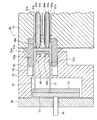
図1は本発明の基本的な考え方を示すための樹脂成形機の金型装置の構成を示す断面図、図4は樹脂成形機によって成形される成形品の例を示す第1の図である。
【0018】
図4において41は、二種類の樹脂から成る成形品であり、第1の樹脂Aから成る第1層41aと第2の樹脂Bから成る第2層41bとが互いに密着した二層構造を有する。なお、前記成形品41の形状は、図4(a)に示される斜視図においては矩(く)形の板状であるが、いかなるものであってもよく、CD−ROM、DVD−ROM等のように円盤状であってもよい。また、板状のような二次元的形状でなく、凹凸を備えた立体的な三次元的形状であってもよい。例えば、前記成形品41は、ゼリー、プリン等の食料品の容器、カップ、コンテナ、電気製品、電子製品、パーソナルコンピュータやその周辺機器のようなOA(オフィスオートメーション)機器等のハウジングやカバー部材、ICカード等の樹脂製カード、容器のキャップ、中空成形(ブロー成形)に使用される予備成形品(パリソン又はプリフォーム)等であってもよい。また、前記成形品41は、図4(b)に示される断面図のような二層構造を有するものであるが、成形品41のすべての部分において二層構造を有している必要はなく、成形品41の少なくとも一部において、図4(b)に示されるような二層構造を有していればよい。さらに、各層の厚さも均一である必要はなく、場所によって変動するものであってもよい。
【0019】
そして、前記第1の樹脂A及び第2の樹脂Bは、例えば、PET(ポリエチレンテレフタレート)、PC(ポリカーボネイト)、PMMA(ポリメタクリル酸メチル)、PE(ポリエチレン)、AS(スチレン/アクリロニトリル)等であるが、いかなる種類の樹脂であってもよい。また、第1の樹脂Aと第2の樹脂Bとは互いに相違するものであるが、実質的に同一の組成を有する樹脂であり色だけが相違するものであってもよいし、また、添加剤や不純物だけが相違するものであってもよい。さらに、一方が新規に製造された樹脂であり、他方がリサイクルされた樹脂であってもよい。
【0020】
図1において、10は樹脂成形機としての射出成形機における金型装置であり、11は図示されない固定金型支持装置としての固定プラテンの金型取付面に取り付けられた固定金型、12は図示されない可動金型支持装置としての可動プラテンの金型取付面に取付板16を介して取り付けられた可動金型である。ここで、前記固定プラテンは図示されない成形機支持フレーム上に固定され、可動プラテンは、金型取付面の反対側の背面に取り付けられた図示されない金型駆動装置によって、図1における左右方向に移動させられる。なお、前記可動プラテンは、前記固定プラテンと図示されない金型駆動装置支持部材とを連結するタイバーに沿って移動する。
【0021】
また、前記金型駆動装置は、例えば、油圧シリンダ装置、サーボモータ等の駆動源、トグルリンク機構等から成り、駆動源及びトグルリンク機構の固定部が前記金型駆動装置支持部材としてのトグルサポートに固定され、トグルリンク機構の可動端部が前記可動プラテンの背面に取り付けられる。そして、前記駆動源が作動すると、該駆動源の駆動力をトグルリンク機構によって増幅して可動プラテンに伝達して、該可動プラテンを前記固定プラテンに対して移動させ、固定金型11と可動金型12とから成る金型装置10の型閉、型締及び型開を行わせるようになっている。
【0022】
そして、前記射出成形機は、図示されない射出装置を有する。該射出装置は、内部にスクリュが配設された加熱シリンダ、前記スクリュを回転及び進退させる駆動装置、及び、前記加熱シリンダ内に樹脂ペレットを供給するホッパ等の樹脂ペレット供給装置を備え、図示されない射出装置支持フレームに取り付けられている。なお、該射出装置支持フレームは前記成形機支持フレームと共通のものであってもよい。
【0023】
ここで、前記加熱シリンダは電気ヒータ等の加熱装置によって加熱され、前記加熱シリンダ内に供給された樹脂ペレットは、スクリュが駆動装置によって回転させられることによって、搬送されながら加熱され、溶融されて、溶融状態となり、加熱シリンダ内の先端部分に貯留される。そして、所定量の樹脂が加熱シリンダ内の先端部分に貯留されると、前記駆動装置によってスクリュが前進させられるので、溶融状態の樹脂は前記加熱シリンダの先端に取り付けられた射出ノズルから射出させられる。
【0024】
ところで、射出成形機においては、加熱シリンダ内において加熱され、溶融させられた樹脂を高圧で射出して金型装置10の後述されるキャビティ空間内に充填し、該キャビティ空間内において樹脂を冷却し、固化させることによって成形品41を成形するようになっている。この場合、前記スクリュの進退は 図示されない制御装置によって制御される。
【0025】
なお、射出成形機は、互いに独立した二つの射出装置を有し、それぞれの射出装置の射出ノズルから溶融状態の第1の樹脂Aと第2の樹脂Bとが独立して射出されるようになっている。また、溶融状態の樹脂が射出させられる時は、前記加熱シリンダが前進(図1における左方向に移動)させられて、射出ノズルが前記固定プラテンに形成された図示されない貫通孔に挿入され、射出ノズルの先端が固定金型11の背面(図1における右側の面)に取り付けられた図示されないスプルーブッシュの端面に押し付けられた状態となる。これにより、射出ノズルから射出させられた溶融状態の第1の樹脂Aと第2の樹脂Bは、外部に漏れ出すことなく、前記スプルーブッシュ内に形成されたスプルーを通過して固定金型11内部に進入し、該固定金型11内部に配設されランナ22a及びランナ22bを通って、金型装置10が型閉された状態の固定金型11と可動金型12との間に形成されたキャビティ空間内に充填される。
【0026】
図1に示されるように、固定金型11内部にはランナ用貫通孔21a及びランナ用貫通孔21bが形成され、該ランナ用貫通孔21a及びランナ用貫通孔21bの内部にランナ22a及びランナ22bが、それぞれ、配設されている。なお、本実施の形態において、ランナ22a及びランナ22bはホットランナであり、電気ヒータ等から成る加熱装置23a及び加熱装置23bをそれぞれ備え、内部を流通する溶融状態の第1の樹脂Aと第2の樹脂Bは加熱されて所定の温度に維持される。
【0027】
また、前記ランナ22a及びランナ22bの内部には、ゲートピンとしてのバルブゲートピン24a及びバルブゲートピン24bが進入している。ここで、該バルブゲートピン24a及びバルブゲートピン24bは、その基部が前記固定プラテンに取り付けられている空圧シリンダ装置等のゲートピン駆動機構に取り付けられ、金型装置10の開閉方向、すなわち、図1における横方向に移動させられる。
【0028】
ここで、前記固定金型11と可動金型12とが互いに接触する面、すなわち、固定金型11のパーティング面11a及び可動金型12のパーティング面12aの一方にはインサートブロック15が取り付けられ、他方には該インサートブロック15の突出部が収容される受溝としてのインサートブロック受溝13が形成され、インロウ結合によって、キャビティ空間内に充填された溶融樹脂が前記パーティング面の隙(すき)間から漏れ出すことが防止される。すなわち、前記インサートブロック15によって、固定金型11のパーティング面11aと可動金型12のパーティング面12aとの間に形成されるキャビティ空間の外延が規定される。なお、インサートブロック受溝13が固定金型11に形成され、インサートブロック15が可動金型12に取り付けられているが、インサートブロック受溝13が可動金型12に形成され、インサートブロック15が固定金型11に取り付けられていてもよい。
【0029】
そして、前記ランナ22a及びランナ22bの先端(図1における左端)は、前記固定金型11のパーティング面11aにおけるインサートブロック15に囲まれた部分に形成されたゲート孔に接続される。これにより、射出ノズルから射出させられた溶融状態の第1の樹脂A及び第2の樹脂Bは、前記ランナ22a及びランナ22bを通ってキャビティ空間内に充填される。
【0030】
なお、図1に示される状態においては、前記キャビティ空間内に第2の樹脂Bが充填されて第2層41bが形成された後、第1の樹脂Aが充填されて第1層41aが形成された状態が示されている。この状態において、前記第1層41a及び第2層41bは圧縮されておらず、また、冷却されてもおらず、後述されるように、この後、圧縮されて冷却され、成形品41が成形される。
【0031】
そして、図1に示される状態においては、バルブゲートピン24a及びバルブゲートピン24bの先端が、ランナ22a及びランナ22bの先端に形成されたゲート孔内に進入して該ゲート孔を閉塞し、前記ゲートピン駆動機構は所定の力でバルブゲートピン24a及びバルブゲートピン24bをゲート孔の方向に押し付け続ける保圧状態となっている。一方、バルブゲートピン24a及びバルブゲートピン24bの先端は、キャビティ空間内の樹脂の圧力によって、前記バルブゲートピン24a及びバルブゲートピン24bをゲートピン駆動機構の方向に押し付ける力を受けている。
【0032】
また、バルブゲートピン24bに安全弁としての機能が付与されており、キャビティ空間内の樹脂の圧力が所定値以上となった場合に、バルブゲートピン24bがゲートピン駆動機構の方向に移動してゲート孔を開放し、キャビティ空間内の樹脂がランナ22b内に逆流することができるようになっている。これにより、キャビティ空間内の樹脂の圧力が過大になって、金型装置10が破損することを防止することができる。なお、バルブゲートピン24aに安全弁としての機能が付与されるようにしてもよい。
【0033】
また、可動金型12の背面(図1における左側の面)と取付板16との間には、エジェクタプレート収容空間部17が形成され、該エジェクタプレート収容空間部17内には、互いに結合された第1エジェクタプレート32及び第2エジェクタプレート33が移動可能に配設されている。ここで、前記第1エジェクタプレート32には、図示されないエジェクタ駆動装置によって図1における左右方向に移動させられる駆動ロッド34の先端が取り付けられている。また、第1エジェクタプレート32と第2エジェクタプレート33との間には、複数のエジェクタピン31の基端部が取り付けられている。そして、前記エジェクタピン31の先端部は、キャビティ空間に連通するように可動金型12に形成されたエジェクタピン挿入孔内に挿入されている。
【0034】
なお、図1に示される状態において、前記エジェクタピン31の先端面は、前記キャビティ空間内に突出しない位置にある。そして、後述されるように、成形品41が形成され金型装置10の型開が行われると、エジェクタ駆動装置が作動して、第1エジェクタプレート32及び第2エジェクタプレート33が図1における右方向に移動させられる。すると、前記エジェクタピン31も移動させられ、該エジェクタピン31の先端面が突出してキャビティ空間内に進入し、前記成形品41をエジェクトする、すなわち、金型装置10外へ突出するようになっている。
【0035】
また、樹脂成形機は、図示されない制御装置を有する。該制御装置は、CPU、MPU等の制御手段、磁気ディスク、半導体メモリ等の記憶手段、キーボード、タッチパネル、ダイヤル、押しボタン、マウス等の入力手段、CRT、液晶ディスプレイ、LED(Light Emitting Diode)ディスプレイ等の表示手段、通信インターフェイス等を備え、前記金型駆動装置、射出装置、ゲートピン駆動機構等の動作を含む、樹脂成形機の動作を統括的に制御する。
【0036】
次に、前記構成の樹脂成形機の動作について説明する。
【0037】
図5は金型装置の断面図であり型閉が開始される状態を示す図、図6は金型装置の断面図であり型閉された状態を示す図、図7は金型装置の断面図であり第2の樹脂の充填開始直後の状態を示す図、図8は金型装置の断面図であり第2の樹脂の充填終了直前の状態を示す図、図9は金型装置の断面図であり型開を一時停止した状態を示す図、図10は金型装置の断面図であり第1の樹脂の充填終了直前の状態を示す図、図11は金型装置の断面図であり型締された状態を示す図、図12は金型装置の断面図であり型開された状態を示す図である。
【0038】
まず、成形を開始する前には、金型駆動装置によって可動プラテン及び該可動プラテンに取り付けられた可動金型12が後退(図1における左方向に移動)した状態になっているので、金型装置10は、図5に示されるように、型開された状態になっている。また、バルブゲートピン24a及びバルブゲートピン24bの先端がランナ22a及びランナ22bの先端に形成されたゲート孔内に進入して該ゲート孔を閉塞した状態になっている。さらに、エジェクタ駆動装置によって第1エジェクタプレート32及び第2エジェクタプレート33が後退(図1における左方向に移動)した状態になっているので、エジェクタピン31の先端面は、図5に示されるように、キャビティ空間内に突出しない位置にある。なお、固定金型11のパーティング面11aにおけるインサートブロック受溝13に囲まれた部分には凹部11bが形成されていることが分かる。
【0039】
続いて、独立した二つの射出装置のそれぞれにおいて、溶融状態の樹脂の計量が完了すると、すなわち、所定量の樹脂が加熱シリンダ内の先端部分に貯留されると、制御装置が型閉信号を出力し、型閉工程が開始され、前記金型駆動装置が作動して可動金型12が前進させられる。これにより、可動金型12が固定金型11に接近する。そして、図6に示されるように、前記可動金型12のパーティング面12aと固定金型11のパーティング面11aとが接触して、前記金型駆動装置が停止し、型閉された状態となる。これにより、インサートブロック15に囲まれた部分の固定金型11のパーティング面11aと可動金型12のパーティング面12aとの間に前記凹部11bによってキャビティ空間が形成される。なお、該キャビティ空間における可動金型12のパーティング面12aと固定金型11のパーティング面11aとの距離は、図4に示されるような成形品41における第2の樹脂Bから成る第2層41bの厚さよりもわずかに大きくなっている。
【0040】
続いて、バルブゲートピン24bのゲートピン駆動機構が作動して前記バルブゲートピン24bが後退(図1における右方向に移動)し、ランナ22bの先端に形成されたゲート孔が開放される。また、第2の樹脂Bの射出装置のスクリュが前進させられ、溶融状態の第2の樹脂Bが射出され、ランナ22bを通って、前記キャビティ空間内に流入する。これにより、図7に示されるように、第2層41bを形成する第2の樹脂Bの充填が開始される。なお、バルブゲートピン24aのゲートピン駆動機構は作動せず、また、第1の樹脂Aの射出装置のスクリュも前進させられないので、この時点で、第1の樹脂Aは充填されない。
【0041】
そして、第2の樹脂Bの充填が継続され、図8に示されるように、第2の樹脂Bが前記キャビティ空間内にほぼ充満する。このとき、可動金型12は、前記第2の樹脂Bによって後退する方向の押圧力を受ける。そこで、金型駆動装置は、可動金型12が後退しないようにするために、可動プラテンに対して前進させる方向の押圧力を加え、前記可動金型12の位置が一定となるように位置制御を行う。また、バルブゲートピン24aも前記第2の樹脂Bによって後退する方向の押圧力を受けるので、バルブゲートピン24aのゲートピン駆動機構は、バルブゲートピン24aが後退してゲート孔が開放されないように、バルブゲートピン24aに対して前進させる方向の押圧力を加える。これにより、前記キャビティ空間内に充填された第2の樹脂Bは、周囲から一定の圧力を受けて保圧される。なお、第2の樹脂Bの充填が完了すると、バルブゲートピン24bのゲートピン駆動機構が作動して前記バルブゲートピン24bが前進して、ランナ22bの先端に形成されたゲート孔が閉塞される。
【0042】
続いて、前記金型駆動装置が作動して可動金型12が後退させられ、わずかに型開が行われる。そして、図9に示されるように、固定金型11のパーティング面11aと可動金型12のパーティング面12aとの間が所定の距離だけ開くと、前記金型駆動装置が停止して型開が一時停止される。この場合、インサートブロック15は、インサートブロック受溝13から抜けきっておらず、前記インサートブロック15の突出部がインサートブロック受溝13内に残留している。これにより、インサートブロック15に囲まれた部分の固定金型11のパーティング面11aと前記第2の樹脂Bによって形成された第2層41bとの間に前記凹部11bによってキャビティ空間が形成される。なお、該キャビティ空間における第2層41bと固定金型11のパーティング面11aとの距離は、図4に示されるような成形品41における第1の樹脂Aから成る第1層41aの厚さよりもわずかに大きくなっている。
【0043】
続いて、バルブゲートピン24aのゲートピン駆動機構が作動して前記バルブゲートピン24aが後退し、ランナ22aの先端に形成されたゲート孔が開放される。また、第1の樹脂Aの射出装置のスクリュが前進させられ、溶融状態の第1の樹脂Aが射出され、ランナ22aを通って、前記キャビティ空間内に流入する。なお、バルブゲートピン24bのゲートピン駆動機構は作動せず、ランナ22bの先端に形成されたゲート孔が閉塞されている。そして、第1の樹脂A41aの充填が継続され、図10に示されるように、第1層を形成する第1の樹脂Aが前記キャビティ空間内にほぼ充満する。このとき、可動金型12は、前記第1の樹脂Aによって後退する方向の押圧力を受ける。そこで、金型駆動装置は、可動金型12が後退しないようにするために、可動プラテンに対して前記可動金型12の位置が一定となるように位置制御を行う。なお、第1の樹脂Aの充填が完了すると、バルブゲートピン24aのゲートピン駆動機構が作動して前記バルブゲートピン24aが前進して、ランナ22aの先端に形成されたゲート孔が閉塞される
続いて、前記金型駆動装置が作動して可動金型12が前進させられ型締が行われる。これにより、キャビティ空間内の第1の樹脂A及び第2の樹脂Bは圧縮される。この場合、バルブゲートピン24bに安全弁としての機能が付与されており、キャビティ空間内の樹脂の圧力が所定値以上となった場合に、バルブゲートピン24bがゲートピン駆動機構の方向に移動してゲート孔を開放し、キャビティ空間内の第1の樹脂A及び第2の樹脂Bがランナ22b内に逆流することができる。これにより、キャビティ空間内の圧力が過大にならないので、金型装置10が破損することがない。
【0044】
続いて、所定の時間が経過して前記第1の樹脂A及び第2の樹脂Bが所定の温度にまで冷却されると、前記金型駆動装置が作動して可動金型12が後退させられ型開が行われる。これにより、図4(a)に示されるような第1の樹脂Aから成る第1層41aと第2の樹脂Bから成る第2層41bとが互いに密着した二層構造を有する成形品41が成形される。そして、可動金型12のパーティング面12aと固定金型11のパーティング面11aとの距離が所定値以上となると、エジェクタ駆動装置が作動して、第1エジェクタプレート32及び第2エジェクタプレート33が図1における右方向に移動させられる。すると、前記エジェクタピン31も移動させられ、該エジェクタピン31の先端面が可動金型12のパーティング面12aから突出してキャビティ空間内に進入し、図12に示されるように、前記成形品41をエジェクトする。これにより、成形品41は可動金型12から離れて落下する。なお、落下することによって、成形品41が損傷する恐れがある場合には、図示されない成形品取り出し機を使用して、成形品41を落下させることなく、金型装置10から取り外すこともできる。
【0045】
次に、樹脂成形機の動作シーケンスについて説明する。
【0046】
図13は樹脂成形機の動作シーケンスを示す図である。
【0047】
本実施の形態において、樹脂成形機の金型装置10及び射出装置は、図13に示されるように作動する。まず、図13(a)は、金型装置10の可動プラテンの位置の時間に対応した変化を示すものであり、横軸は時間を示し、縦軸は可動金型12の位置を示している。なお、前記縦軸は可動金型12が前進するほど、すなわち、可動金型12が固定金型11に接近するほど数値が小さくなるように示されている。また、図13(b)は、第2の樹脂Bの射出装置のスクリュの位置の時間に対応した変化を示すものであり、横軸は時間を示し、縦軸はスクリュの位置を示している。なお、前記縦軸はスクリュが前進するほど、すなわち、射出ノズルに接近するほど数値が小さくなるように示されている。そして、図13(c)は、第1の樹脂Aの射出装置のスクリュの位置の時間に対応した変化を示すものであり、横軸は時間を示し、縦軸はスクリュの位置を示している。なお、前記縦軸はスクリュが前進するほど、すなわち、射出ノズルに接近するほど数値が小さくなるように示されている。また、図13(a)〜(c)において、時間を示す横軸のスケールは共通である。
【0048】
図13に示されるように、第1の樹脂Aの射出装置及び第2の樹脂Bの射出装置において溶融状態の樹脂の計量が完了すると、金型装置10が型開された状態において、型閉工程が開始され、可動金型12が前進する。そして、図6に示されるように、前記可動金型12のパーティング面12aと固定金型11のパーティング面11aとが接触して、可動金型12が停止し、型閉された状態となる。
【0049】
そして、バルブゲートピン24bが後退し、ランナ22bの先端に形成されたゲート孔が開放される。また、第2の樹脂Bの射出装置のスクリュが前進し、溶融状態の第2の樹脂Bが射出され、ランナ22bを通って、キャビティ空間内に充填される。
【0050】
続いて、所定の時間だけ第2の樹脂Bの保圧が行われた後、可動金型12が後退させられ、わずかに型開が行われる。そして、図9に示されるように、固定金型11のパーティング面11aと可動金型12のパーティング面12aとの間が所定の距離だけ開くと、前記可動金型12が停止して型開が一時停止される。なお、前記第2の樹脂Bの射出装置のスクリュは元の位置にまで後退する。
【0051】
そして、バルブゲートピン24aが後退し、ランナ22abの先端に形成されたゲート孔が開放される。また、第1の樹脂Aの射出装置のスクリュが前進し、溶融状態の第1の樹脂Aが射出され、ランナ22aを通って、キャビティ空間内に充填される。この場合も、前記スクリュを前進させる動きは、溶融状態の第1の樹脂Aの圧力に無関係に前進するスクリュの位置を制御する簡単な位置制御によって行われる。
【0052】
続いて、所定の時間だけ第1の樹脂Aの保圧が行われた後、可動金型12が前進させられ型締が行われる。なお、前記第1の樹脂Aの射出装置のスクリュは元の位置にまで後退する。そして、所定の時間が経過すると、可動金型12が後退させられ型開が行われ、成形品41が取り出される。
【0053】
また、本実施の形態における樹脂成形機は、三層以上層構造を有する成形品を成形することもできる。
【0054】
次に、本発明の第1の実施の形態について説明する。なお、前記本発明の基本的な考え方で説明したものと同じ構成を有するもの及び同じ動作については、その説明を省略する。
【0055】
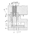
図14は本発明の第1の実施の形態における樹脂成形機によって成形される成形品の例を示す断面図、図15は本発明の第1の実施の形態における樹脂成形機の金型装置の構成を示す断面図である。
【0056】
本実施の形態における成形品46は、図14に示されるように、二層構造を有し、「従来の技術」において説明したパッキン付ねじキャップ101と同様に、ボトルの口部に螺合されて、該ボトルの口部の開放端を密封するようになっている。そのため、第1の樹脂Aから成る構成部としてのねじキャップ本体46aの内面には雌ねじ46a−1が一体的に形成されている。なお、前記第1の樹脂AはPP樹脂であることが望ましい。
【0057】
また、ねじキャップ本体46aの内側天井面にはパッキン樹脂としての第2の樹脂Bから成る構成部としてのパッキン46bが密着して層構造をなしている。なお、前記パッキン46bは、「従来の技術」において説明したパッキン103と同様に、ボトルの口部の外面、内面及び天面を確実にシールするために、アウターシール部46b−1、インナーシール部46b−2及びトップシール部46b−3を備える。また、前記第2の樹脂BはPE樹脂であることが望ましい。
【0058】
図15において、50は本実施の形態における金型装置であり、51は固定金型、52は可動金型、56は取付板である。そして、前記固定金型51内部にはランナ用貫通孔61a及びランナ用貫通孔61bが形成され、前記ランナ用貫通孔61a及びランナ用貫通孔61bの内部にランナ62a及びランナ62bが、それぞれ、配設されている。なお、本実施の形態において、ランナ62a及びランナ62bはホットランナであり、電気ヒータ等から成る加熱装置63a及び加熱装置63bを、それぞれ、備える。また、前記ランナ62a及びランナ62bの内部には、ゲートピンとしてのバルブゲートピン64a及びバルブゲートピン64bが進入している。
【0059】
ここで、固定金型51のパーティング面51a及び可動金型52のパーティング面52aの一方にはインサートブロック55が取り付けられ、他方には該インサートブロック55の突出部が収容される受溝としてのインサートブロック受溝53が形成され、インロウ結合によって、固定金型51のパーティング面51aと可動金型52のパーティング面52aとの間に隙間が生じてもキャビティ空間内に充填された溶融樹脂が前記パーティング面の隙間から漏れ出すことが防止される。本実施の形態において、前記インサートブロック55及びインサートブロック受溝53はリング状(環状)であり、前記インサートブロック55によって、固定金型51のパーティング面51aと可動金型52のパーティング面52aとの間に形成されるキャビティ空間の外延が規定される。また、可動金型52のインサートブロック受溝53に囲まれた部分には、ねじキャップ本体46aのねじ部及びパッキン46bを形成するための凸部52bが形成されている。そして、該凸部52bの周部には、前記ねじキャップ本体46aのねじ部を形成するねじ部凹部53aと、前記凸部52bの先端には、前記パッキン46bを形成するための凹部としてのパッキン凹部48が形成されている。なお、本実施の形態においては、インサートブロック受溝53が可動金型52に形成され、インサートブロック55が固定金型51に取り付けられているが、インサートブロック受溝53が固定金型51に形成され、インサートブロック55が可動金型52に取り付けられていてもよい。
【0060】
そして、前記ランナ62a及びランナ62bの先端は、前記固定金型51のパーティング面51aにおけるインサートブロック55に囲まれた部分に形成されたゲート孔に接続される。これにより、射出ノズルから射出させられた溶融状態の第1の樹脂A及び第2の樹脂Bは、前記ランナ62a及びランナ62bを通ってキャビティ空間内に充填される。
【0061】
そして、可動金型52の背面と取付板56との間には、エジェクタプレート収容空間部57が形成され、該エジェクタプレート収容空間部57内には、互いに結合された第1エジェクタプレート72及び第2エジェクタプレート73が移動可能に配設されている。ここで、前記第1エジェクタプレート72には、駆動ロッド74の先端が取り付けられている。また、第1エジェクタプレート72と第2エジェクタプレート73との間には、複数のエジェクタピン71の基端部が取り付けられている。そして、前記エジェクタピン71の先端部は、キャビティ空間に連通するように可動金型52に形成されたエジェクタピン挿入孔内に挿入されている。
【0062】
次に、前記構成の樹脂成形機の動作について説明する。
【0063】
図16は本発明の第1の実施の形態における金型装置の断面図であり型閉が開始される状態を示す図、図17は本発明の第1の実施の形態における金型装置の断面図であり型閉された状態を示す図、図18は本発明の第1の実施の形態における金型装置の断面図であり型開を一時停止した状態を示す図、図19は本発明の第1の実施の形態における金型装置の断面図であり第1の樹脂の充填後の状態を示す図、図20は本発明の第1の実施の形態における金型装置の断面図であり型締された状態を示す図、図21は本発明の第1の実施の形態における金型装置の断面図であり型開された状態を示す図、図22は本発明の第1の実施の形態における金型装置の断面図であり成形品がエジェクトされた状態を示す図である。
【0064】
まず、成形を開始する前には、金型駆動装置によって可動プラテン及び該可動プラテンに取り付けられた可動金型52が後退(図15における左方向に移動)した状態になっているので、金型装置50は、図16に示されるように、型開された状態になっている。また、バルブゲートピン64a及びバルブゲートピン64bの先端がランナ62a及びランナ62bの先端に形成されたゲート孔内に進入して該ゲート孔を閉塞した状態になっている。さらに、エジェクタ駆動装置によって第1エジェクタプレート72及び第2エジェクタプレート73が後退(図15における左方向に移動)した状態になっているので、エジェクタピン71の先端面は、図16に示されるように、キャビティ空間に突出しない位置にある。
【0065】
続いて、独立した二つの射出装置のそれぞれにおいて、溶融状態の樹脂の計量が完了すると、すなわち、所定量の樹脂が加熱シリンダ内の先端部分に貯留されると、制御装置が型閉信号を出力し、型閉工程が開始され、前記金型駆動装置が作動して可動プラテンが前進させられる。これにより、可動金型52が固定金型51に接近する。そして、図17に示されるように、前記可動金型52のパーティング面52aと固定金型51のパーティング面51aとが接触して、前記金型駆動装置が停止し、型閉された状態となる。
【0066】
続いて、バルブゲートピン64bのゲートピン駆動機構が作動して前記バルブゲートピン64bが後退(図15における右方向に移動)し、ランナ62bの先端に形成されたゲート孔が開放される。また、第2の樹脂Bの射出装置のスクリュが前進させられ、溶融状態の第2の樹脂Bが射出され、ランナ62bを通って、可動金型52のパーティング面52aにおけるインサートブロック55に囲まれた部分に対応する箇所に形成されたパッキン凹部48内に流入する。これにより、第2の樹脂Bの充填が開始される。なお、バルブゲートピン64aのゲートピン駆動機構は作動せず、また、第1の樹脂Aの射出装置のスクリュも前進させられないので、この時点で、第1の樹脂Aは充填されない。
【0067】
そして、第2の樹脂Bの充填が継続され、第2の樹脂Bが前記パッキン凹部48内にほぼ充満する。このとき、可動金型52は、前記第2の樹脂Bによって後退する方向の押圧力を受ける。そこで、金型駆動装置は、可動金型52が後退しないようにするために、可動プラテンに対して前進させる方向の押圧力を加え、前記可動金型52の位置が一定となるように位置制御を行う。しかし、前記パッキン凹部48の断面積が小さいので、金型駆動装置が可動プラテンに対して加える押圧力は大きくなくてよい。また、バルブゲートピン64aも前記第2の樹脂Bによって後退する方向の押圧力を受けるので、バルブゲートピン64aのゲートピン駆動機構は、バルブゲートピン24aが後退してゲート孔が開放されないように、バルブゲートピン64aに対して前進させる方向の押圧力を加える。これにより、前記キャビティ空間内に充填された第2の樹脂Bは、周囲から一定の圧力を受けて保圧される。なお、第2の樹脂Bの充填が完了すると、バルブゲートピン64bのゲートピン駆動機構が作動して前記バルブゲートピン64bが前進して、ランナ62bの先端に形成されたゲート孔が閉塞される。
【0068】
続いて、前記金型駆動装置が作動して可動プラテンが後退させられ、わずかに型開が行われる。そして、図18に示されるように、固定金型51のパーティング面51aと可動金型52のパーティング面52aとの間が所定の距離だけ開くと、前記金型駆動装置が停止して型開が一時停止される。この場合、インサートブロック55は、インサートブロック受溝53から抜けきっておらず、前記インサートブロック55の突出部がインサートブロック受溝53内に残留している。これにより、インサートブロック55に囲まれた部分の固定金型51のパーティング面51aと前記第2の樹脂Bによって形成されたパッキン46bとの間にキャビティ空間が形成される。なお、該キャビティ空間におけるパッキン46bと固定金型51のパーティング面51aとの距離は、図14に示されるような成形された成形品46における第1の樹脂Aから成るねじキャップ本体46aの厚さよりもわずかに大きくなっている。
【0069】
続いて、バルブゲートピン64aのゲートピン駆動機構が作動して前記バルブゲートピン64aが後退し、ランナ62aの先端に形成されたゲート孔が開放される。また、第1の樹脂Aの射出装置のスクリュが前進させられ、溶融状態の第1の樹脂Aが射出され、ランナ62aを通って、前記キャビティ空間内に流入する。なお、バルブゲートピン64bのゲートピン駆動機構は作動せず、ランナ62bの先端に形成されたゲート孔が閉塞されている。そして、第1の樹脂Aの充填が継続され、図19に示されるように、ねじキャップ本体46を形成する第1の樹脂Aが前記キャビティ空間内に充填される。このとき、可動金型52は、前記第1の樹脂Aによって後退する方向の押圧力を受ける。そこで、金型駆動装置は、可動金型52が後退しないようにするために、前記可動金型52の位置が一定となるように位置制御を行う。なお、第1の樹脂Aの充填が完了すると、バルブゲートピン64aのゲートピン駆動機構が作動して前記バルブゲートピン64aが前進して、ランナ62aの先端に形成されたゲート孔が閉塞される。
【0070】
続いて、前記金型駆動装置が作動して可動プラテンが前進させられ型締が行われる。この場合、図20に示されるように、可動金型52のパーティング面52aと固定金型51のパーティング面51aとが接近するまで、可動プラテンが前進させられる。これにより、キャビティ空間内の第1の樹脂Aは圧縮される。この場合、バルブゲートピン64bに安全弁としての機能が付与されており、キャビティ空間内の樹脂の圧力が所定値以上となった場合に、バルブゲートピン64bがゲートピン駆動機構の方向に移動してゲート孔を開放し、キャビティ空間内の第1の樹脂A及び第2の樹脂Bがランナ62b内に逆流することができる。これにより、キャビティ空間内の圧力が過大にならないので、金型装置50が破損することがない。
【0071】
続いて、所定の時間が経過して前記第1の樹脂A及び第2の樹脂Bが所定の温度にまで冷却されると、図21に示されるように、前記金型駆動装置が作動して可動プラテンが後退させられ型開が行われる。これにより、図14に示されるような成形品46が成形される。そして、可動金型52のパーティング面52aと固定金型51のパーティング面51aとの距離が所定値以上となると、エジェクタ駆動装置が作動して、第1エジェクタプレート72及び第2エジェクタプレート73が右方向に移動させられる。すると、前記エジェクタピン71も移動させられ、該エジェクタピン71の先端面が突出して、図22に示されるように、前記成形品46をエジェクトする。ここで、前記エジェクタピン71の先端面は、前記成形品46のねじキャップ本体46aの端面を押すようになっているので、ねじキャップ本体46aの内面に形成された雌ねじ46a−1に対応する部分がアンダーカットとなっているにも関わらず、成形品46はスムーズにエジェクトされる。これにより、成形品46は金型装置50から離れて落下する。
【0072】
このように、本実施の形態においては、簡単な構成の金型装置50を使用して、可動金型52の位置と、樹脂を金型装置50のキャビティ空間内に充填する動作のタイミングとを制御するだけで、多層構造を有し、かつ、複雑な形状を有する成形品を容易に成形することができる。
【0073】
次に、本発明の第2の実施の形態について説明する。なお、前記第1の実施の形態と同じ構造を有するもの及び動作については、その説明を省略する。
【0074】
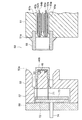
図23は本発明の第2の実施の形態における樹脂成形機の金型装置の構成を示す断面図である。
【0075】
本実施の形態においては、可動金型52にインサートブロック55が取り付けられ、固定金型51にインサートブロック受溝53が形成されている。
【0076】
次に、本発明の第3の実施の形態について説明する。なお、前記第1の実施の形態と同じ構造を有するもの及び動作については、その説明を省略する。
【0077】
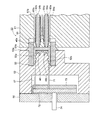
図24は本発明の第3の実施の形態における樹脂成形機の金型装置の構成を示す断面図である。
【0078】
本実施の形態においては、固定金型51のランナ62a及びランナ62bが位置する部分がパーティング面51aより突出した凸部51bが形成され、該凸部51bの対向する可動金型52には、前記凸部51bに嵌入する凹部52cが形成されている。
【0079】
また、該凹部52cの中央には、固定金型51に向かって凸部52bが形成されている。凸部52bの周部には、前記ねじキャップ本体46aのねじ部を形成するねじ部凹部53aと、前記凸部52aの先端には、前記パッキン46bを形成するためのパッキン凹部48が形成されている。
【0080】
なお、前記の実施の形態においては、可動プラテンが横方向(水平方向)に移動する横置型の射出成形機について説明したが、本発明の樹脂成形機及び樹脂成形方法は、可動プラテンが縦方向(垂直方向)に移動する縦置型の射出成形機にも適用することができる。さらに、本発明の樹脂成形機及び樹脂成形方法は、射出成形機の他に、ダイキャストマシーン、IJ封止プレス等の成形機にも適用することができる。
【0081】
また、本発明は前記実施の形態に限定されるものではなく、本発明の趣旨に基づいて種々変形させることが可能であり、それらを本発明の範囲から排除するものではない。
【0082】
【発明の効果】
以上詳細に説明したように、本発明によれば、樹脂成形方法においては、固定金型と可動金型とを型閉して形成された第1の空間に、ゲートピンを備える一方のゲート孔から樹脂を充填し、該樹脂の充填が完了した後、前記可動金型を後退させ、前記固定金型と可動金型との間隔を広げて第2の空間を形成し、該第2の空間に、ゲートピンを備える他方のゲート孔から樹脂を充填して成形品を形成する樹脂成形方法であって、前記固定金型及び可動金型の一方にはインサートブロックが取り付けられ、前記固定金型及び可動金型の他方には前記インサートブロックの突出部を収納する受溝が形成され、前記樹脂の充填が完了した後、前記可動金型を後退させ、前記固定金型と可動金型との間隔を広げ、前記固定金型と可動金型と前記インサートブロックの少なくとも一部とで、前記第2の空間を形成する。
【0083】
この場合、可動金型の位置と、樹脂を充填する動作のタイミングとを制御するだけで、所定の構造の成形品を容易に成形することができる。
【0085】
この場合、パッキン付ねじキャップを容易に成形することができる。
【0086】
樹脂成形用金型装置においては、固定金型と、該固定金型と嵌合する可動金型と、前記固定金型と可動金型とを型閉して形成された第1の空間に連通する一方のゲート孔に備えられた第1のゲートピンと、樹脂の充填が完了した後、前記可動金型を後退させ、前記固定金型と可動金型との間隔を広げて形成された第2の空間に連通する他方のゲート孔に備えられた第2のゲートピンとを備える樹脂成形用金型装置であって、前記固定金型と可動金型との嵌合は、前記固定金型及び可動金型の一方に取り付けられるインサートブロックと、前記固定金型及び可動金型の他方に形成され、前記インサートブロックの突出部を収納する受溝とにより行われる。
【0087】
この場合、簡単な構成の金型装置を使用して、可動金型の位置と、樹脂をキャビティ空間内に充填する動作のタイミングとを制御するだけで、所定の構造の成形品を容易に成形することができる。
【0089】
この場合、充填された溶融樹脂が前記パーティング面の隙間から漏れ出すことがないので、バリが発生してしまうことがない。
【0091】
この場合、充填された溶融樹脂が前記パーティング面の隙間から漏れ出すことがないので、バリが発生してしまうことがない。
【図面の簡単な説明】
【図1】本発明の基本的な考え方を示すための樹脂成形機の金型装置の構成を示す断面図である。
【図2】従来のパッキン付ねじキャップの構成を示す一部断面斜視図である。
【図3】従来のパッキン付ねじキャップの構成を示す断面図である。
【図4】樹脂成形機によって成形される成形品の例を示す第1の図である。
【図5】金型装置の断面図であり型閉が開始される状態を示す図である。
【図6】金型装置の断面図であり型閉された状態を示す図である。
【図7】金型装置の断面図であり第2の樹脂の充填開始直後の状態を示す図である。
【図8】金型装置の断面図であり第2の樹脂の充填終了直前の状態を示す図である。
【図9】金型装置の断面図であり型開を一時停止した状態を示す図である。
【図10】金型装置の断面図であり第1の樹脂の充填終了直前の状態を示す図である。
【図11】金型装置の断面図であり型締された状態を示す図である。
【図12】金型装置の断面図であり型開された状態を示す図である。
【図13】樹脂成形機の動作シーケンスを示す図である。
【図14】本発明の第1の実施の形態における樹脂成形機によって成形される成形品の例を示す断面図である。
【図15】本発明の第1の実施の形態における樹脂成形機の金型装置の構成を示す断面図である。
【図16】本発明の第1の実施の形態における金型装置の断面図であり型閉が開始される状態を示す図である。
【図17】本発明の第1の実施の形態における金型装置の断面図であり型閉された状態を示す図である。
【図18】本発明の第1の実施の形態における金型装置の断面図であり型開を一時停止した状態を示す図である。
【図19】本発明の第1の実施の形態における金型装置の断面図であり第1の樹脂の充填後の状態を示す図である。
【図20】本発明の第1の実施の形態における金型装置の断面図であり型締された状態を示す図である。
【図21】本発明の第1の実施の形態における金型装置の断面図であり型開された状態を示す図である。
【図22】本発明の第1の実施の形態における金型装置の断面図であり成形品がエジェクトされた状態を示す図である。
【図23】本発明の第2の実施の形態における樹脂成形機の金型装置の構成を示す断面図である。
【図24】本発明の第3の実施の形態における樹脂成形機の金型装置の構成を示す断面図である。
【符号の説明】
11、51 固定金型
12、52 可動金型
13、53 インサートブロック受溝
15、55 インサートブロック
24a、24b、64a、64b バルブゲートピン
41、42、43、44、45、46 成形品[0001]
BACKGROUND OF THE INVENTION
The present invention relates to a resin molding method and a resin molding machine.
[0002]
[Prior art]
Conventionally, in a resin molding machine such as an injection molding machine, a resin heated and melted in a heating cylinder is injected at a high pressure and filled in a cavity space of a mold apparatus. By cooling and solidifying the resin, molded articles having various complicated shapes can be formed.
[0003]
FIG. 2 is a partial cross-sectional perspective view showing the configuration of a conventional screw cap with packing, and FIG. 3 is a cross-sectional view showing the configuration of a conventional screw cap with packing.
[0004]
In FIG. 2,
[0005]
Here, as shown in FIGS. 3B and 3C, the
[0006]
[Problems to be solved by the invention]
However, in the conventional resin molding machine, it is difficult to mold a molded product having a complicated shape and made of a plurality of types of resins, like the
[0007]
However, in the past, an injection molding machine equipped with a plurality of injection devices was used, and a multi-colored product in which molded products made of a plurality of materials were molded by sequentially injecting different resin materials from the respective injection devices into a mold. A material forming apparatus is provided. For example, a rotary type in which a mold rotates and a slide type molding apparatus in which the mold moves in a direction perpendicular to an axis, that is, in a lateral direction are known. However, in the molding apparatus, each time a resin of a different material is injected from each injection apparatus, the mold is rotated or slid in the lateral direction. Therefore, there are many molding processes, and molding takes time. Further, since the number of molded products to be obtained with respect to the size of the mold is reduced (for example, half of the two-color molding), the mold is enlarged with respect to the throughput, and the cost of the resin molding machine is increased. End up. Further, the structure of the mold becomes complicated. In addition, a core back type molding apparatus in which only a part of the mold is moved in the axial direction by a hydraulic device is also known, but in this case, the structure of the mold becomes complicated and the cost of the resin molding machine increases. End up. In addition, since there are many restrictions on the shape of the molded product, it is difficult to mold a molded product having a complicated shape.
[0008]
The present invention solves the above-mentioned conventional problems, and even a molded product made of a plurality of materials can be easily and integrally molded in a short time using a mold having a simple configuration. An object of the present invention is to provide a resin molding method and a resin molding machine that can be used.
[0009]
[Means for Solving the Problems]
Therefore, in the resin molding method of the present invention, the first space formed by closing the fixed mold and the movable mold is filled with the resin from one gate hole provided with the gate pin (co). After the filling of the resin is completed, the movable mold is moved backward to widen the space between the fixed mold and the movable mold to form a second space, and the second space is provided with a gate pin. Filled with resin from the gate hole to form a molded product In the resin molding method, an insert block is attached to one of the fixed mold and the movable mold, and a receiving groove for accommodating the protruding portion of the insert block is formed on the other of the fixed mold and the movable mold. And after the filling of the resin is completed, the movable mold is retracted, the interval between the fixed mold and the movable mold is widened, the fixed mold, the movable mold, and at least a part of the insert block, And forming the second space .
[0011]
In the mold apparatus for resin molding of the present invention, the mold is formed by closing a fixed mold, a movable mold that fits into the fixed mold, and the fixed mold and the movable mold. The first gate pin provided in one gate hole communicating with the first space and after the resin filling is completed, the movable mold is moved backward to widen the interval between the fixed mold and the movable mold. And a second gate pin provided in the other gate hole communicating with the second space formed In the resin molding die apparatus, the fixed mold and the movable mold are fitted to each other by an insert block attached to one of the fixed mold and the movable mold, and the fixed mold and the movable mold. It is formed by a receiving groove that is formed on the other side and accommodates the protruding portion of the insert block. .
[0015]
DETAILED DESCRIPTION OF THE INVENTION
Hereinafter, embodiments of the present invention will be described in detail with reference to the drawings. In the present embodiment, for convenience of explanation, a case where the present invention is applied to an injection molding machine will be described.
[0016]
First, the basic concept of the present invention will be described.
[0017]
FIG. 1 is a cross-sectional view showing the configuration of a mold apparatus of a resin molding machine for illustrating the basic concept of the present invention, and FIG. 4 is a first diagram showing an example of a molded product molded by the resin molding machine. .
[0018]
In FIG. 4,
[0019]
The first resin A and the second resin B are, for example, PET (polyethylene terephthalate), PC (polycarbonate), PMMA (polymethyl methacrylate), PE (polyethylene), AS (styrene / acrylonitrile), and the like. However, any type of resin may be used. In addition, the first resin A and the second resin B are different from each other, but may be resins having substantially the same composition and different in color. Only agents and impurities may be different. Furthermore, one may be a newly produced resin and the other may be a recycled resin.
[0020]
In FIG. 1, 10 is a mold apparatus in an injection molding machine as a resin molding machine, 11 is a fixed mold attached to a mold mounting surface of a fixed platen as a fixed mold support apparatus (not shown), and 12 is illustrated. The movable mold is attached to a mold mounting surface of a movable platen as a movable mold support device that is not attached via a mounting
[0021]
In addition, the mold drive device includes, for example, a hydraulic cylinder device, a drive source such as a servo motor, a toggle link mechanism, and the like, and a fixed portion of the drive source and the toggle link mechanism is a toggle support as the mold drive device support member. The movable end of the toggle link mechanism is attached to the back surface of the movable platen. When the drive source is activated, the driving force of the drive source is amplified by a toggle link mechanism and transmitted to the movable platen, and the movable platen is moved relative to the fixed platen. The
[0022]
The injection molding machine has an injection device (not shown). The injection device includes a heating cylinder having a screw disposed therein, a driving device for rotating and reciprocating the screw, and a resin pellet supply device such as a hopper for supplying the resin pellet into the heating cylinder. Attached to the injection device support frame. The injection device support frame may be the same as the molding machine support frame.
[0023]
Here, the heating cylinder is heated by a heating device such as an electric heater, and the resin pellets supplied into the heating cylinder are heated and melted while being conveyed by a screw being rotated by a driving device, It enters a molten state and is stored at the tip portion in the heating cylinder. When a predetermined amount of resin is stored in the tip portion of the heating cylinder, the screw is advanced by the driving device, so that the molten resin is injected from an injection nozzle attached to the tip of the heating cylinder. .
[0024]
By the way, in the injection molding machine, the resin heated and melted in the heating cylinder is injected at a high pressure to fill a cavity space, which will be described later, of the
[0025]
The injection molding machine has two independent injection devices so that the molten first resin A and second resin B are injected independently from the injection nozzles of the respective injection devices. It has become. When the molten resin is injected, the heating cylinder is moved forward (moved leftward in FIG. 1), and an injection nozzle is inserted into a through hole (not shown) formed in the fixed platen. The tip of the nozzle is pressed against the end surface of a sprue bush (not shown) attached to the back surface (right surface in FIG. 1) of the fixed
[0026]
As shown in FIG. 1, a runner through
[0027]
In addition, a
[0028]
Here, the
[0029]
And the front-end | tip (left end in FIG. 1) of the said
[0030]
In the state shown in FIG. 1, after the second resin B is filled in the cavity space to form the
[0031]
In the state shown in FIG. 1, the distal ends of the
[0032]
Further, the
[0033]
Further, an ejector
[0034]
In the state shown in FIG. 1, the tip end surface of the
[0035]
The resin molding machine has a control device (not shown). The control device includes control means such as a CPU and MPU, storage means such as a magnetic disk and semiconductor memory, input means such as a keyboard, a touch panel, a dial, a push button and a mouse, a CRT, a liquid crystal display, and an LED (Light Emitting Diode) display. The operation of the resin molding machine including the operations of the mold driving device, the injection device, the gate pin driving mechanism and the like is comprehensively controlled.
[0036]
Next, the operation of the resin molding machine configured as described above will be described.
[0037]
5 is a cross-sectional view of the mold apparatus showing a state where mold closing is started, FIG. 6 is a cross-sectional view of the mold apparatus showing a state where the mold is closed, and FIG. 7 is a cross-sectional view of the mold apparatus. FIG. 8 is a view showing a state immediately after the start of filling of the second resin, FIG. 8 is a cross-sectional view of the mold apparatus, showing a state immediately before the end of filling of the second resin, and FIG. 9 is a cross section of the mold apparatus. FIG. 10 is a view showing a state in which mold opening is temporarily stopped, FIG. 10 is a cross-sectional view of the mold apparatus, showing a state immediately before the completion of filling with the first resin, and FIG. 11 is a cross-sectional view of the mold apparatus. FIG. 12 is a cross-sectional view of the mold apparatus and shows a state in which the mold is opened.
[0038]
First, before the molding is started, the movable platen and the
[0039]
Subsequently, in each of the two independent injection devices, when the measurement of the molten resin is completed, that is, when a predetermined amount of resin is stored in the tip portion in the heating cylinder, the control device outputs a mold closing signal. Then, the mold closing process is started, the mold driving device is operated, and the
[0040]
Subsequently, the gate pin driving mechanism of the
[0041]
Then, the filling of the second resin B is continued, and as shown in FIG. 8, the second resin B substantially fills the cavity space. At this time, the
[0042]
Subsequently, the mold driving device is operated, the
[0043]
Subsequently, the gate pin driving mechanism of the
Subsequently, the mold driving device is operated, the
[0044]
Subsequently, when the first resin A and the second resin B are cooled to a predetermined temperature after a predetermined time has elapsed, the mold driving device is operated to move the
[0045]
Next, the operation sequence of the resin molding machine will be described.
[0046]
FIG. 13 is a diagram showing an operation sequence of the resin molding machine.
[0047]
In the present embodiment, the
[0048]
As shown in FIG. 13, when the measurement of the molten resin is completed in the first resin A injection device and the second resin B injection device, the mold is closed in the state where the
[0049]
Then, the
[0050]
Subsequently, after holding the second resin B for a predetermined time, the
[0051]
Then, the
[0052]
Subsequently, after the first resin A is held for a predetermined time, the
[0053]
In addition, the resin molding machine in the present embodiment can also mold a molded product having a three-layer structure or more.
[0054]
Next, a first embodiment of the present invention will be described. In addition, the description is abbreviate | omitted about the thing and the same operation | movement which have the same structure as what was demonstrated with the basic idea of the said invention.
[0055]
FIG. 14 is a cross-sectional view showing an example of a molded product molded by the resin molding machine in the first embodiment of the present invention, and FIG. 15 is a diagram of the mold apparatus of the resin molding machine in the first embodiment of the present invention. It is sectional drawing which shows a structure.
[0056]
As shown in FIG. 14, the molded
[0057]
Further, a
[0058]
In FIG. 15, 50 is a mold apparatus in the present embodiment, 51 is a fixed mold, 52 is a movable mold, and 56 is a mounting plate. A runner through
[0059]
Here, an
[0060]
The ends of the
[0061]
An ejector
[0062]
Next, the operation of the resin molding machine configured as described above will be described.
[0063]
FIG. 16 is a sectional view of the mold apparatus according to the first embodiment of the present invention, showing a state in which mold closing is started, and FIG. 17 is a section of the mold apparatus according to the first embodiment of the present invention. FIG. 18 is a diagram showing a state in which the mold is closed, FIG. 18 is a sectional view of the mold apparatus according to the first embodiment of the present invention, showing a state in which mold opening is temporarily stopped, and FIG. FIG. 20 is a cross-sectional view of the mold apparatus according to the first embodiment, and shows a state after filling with the first resin, and FIG. 20 is a cross-sectional view of the mold apparatus according to the first embodiment of the present invention. FIG. 21 is a diagram showing a clamped state, FIG. 21 is a cross-sectional view of the mold apparatus in the first embodiment of the present invention, showing the mold opened, and FIG. 22 is a diagram showing the first embodiment of the present invention. It is sectional drawing of the metal mold | die apparatus in and is a figure which shows the state by which the molded article was ejected.
[0064]
First, before starting molding, the movable platen and the
[0065]
Subsequently, in each of the two independent injection devices, when the measurement of the molten resin is completed, that is, when a predetermined amount of resin is stored in the tip portion in the heating cylinder, the control device outputs a mold closing signal. Then, the mold closing process is started, the mold driving device is operated, and the movable platen is advanced. Thereby, the
[0066]
Subsequently, the gate pin drive mechanism of the
[0067]
Then, the filling of the second resin B is continued, and the second resin B is almost filled in the
[0068]
Subsequently, the mold driving device is operated to retract the movable platen, and the mold is slightly opened. Then, as shown in FIG. 18, when the
[0069]
Subsequently, the gate pin driving mechanism of the
[0070]
Subsequently, the mold driving device is operated, the movable platen is advanced, and mold clamping is performed. In this case, as shown in FIG. 20, the movable platen is advanced until the
[0071]
Subsequently, when the first resin A and the second resin B are cooled to a predetermined temperature after a predetermined time has elapsed, as shown in FIG. The movable platen is moved backward to open the mold. Thereby, a molded
[0072]
As described above, in the present embodiment, the position of the
[0073]
Next, a second embodiment of the present invention will be described. Note that description of operations and operations having the same structure as in the first embodiment will be omitted.
[0074]
FIG. 23 is a cross-sectional view showing a configuration of a mold apparatus of a resin molding machine according to the second embodiment of the present invention.
[0075]
In the present embodiment, an
[0076]
Next, a third embodiment of the present invention will be described. Note that description of operations and operations having the same structure as in the first embodiment will be omitted.
[0077]
FIG. 24 is a cross-sectional view showing a configuration of a mold apparatus of a resin molding machine according to the third embodiment of the present invention.
[0078]
In the present embodiment, a
[0079]
A
[0080]
In the above embodiment, the horizontal type injection molding machine in which the movable platen moves in the horizontal direction (horizontal direction) has been described. However, in the resin molding machine and the resin molding method of the present invention, the movable platen is in the vertical direction. The present invention can also be applied to a vertical injection molding machine that moves in the (vertical direction). Furthermore, the resin molding machine and resin molding method of the present invention can be applied to molding machines such as die-cast machines and IJ sealing presses in addition to injection molding machines.
[0081]
The present invention is not limited to the above-described embodiment, and various modifications can be made based on the spirit of the present invention, and they are not excluded from the scope of the present invention.
[0082]
【The invention's effect】
As described above in detail, according to the present invention, in the resin molding method, the first space formed by closing the stationary mold and the movable mold is closed from one gate hole provided with a gate pin. After the resin is filled and the resin filling is completed, the movable mold is retracted to widen the space between the fixed mold and the movable mold to form a second space. In the second space, The resin is filled from the other gate hole provided with the gate pin to form a molded product. In the resin molding method, an insert block is attached to one of the fixed mold and the movable mold, and a receiving groove for accommodating the protruding portion of the insert block is formed on the other of the fixed mold and the movable mold. And after the filling of the resin is completed, the movable mold is retracted, the interval between the fixed mold and the movable mold is widened, the fixed mold, the movable mold, and at least a part of the insert block, And forming the second space .
[0083]
In this case, a molded article having a predetermined structure can be easily molded by simply controlling the position of the movable mold and the timing of the operation of filling the resin.
[0085]
In this case, the screw cap with packing can be easily formed.
[0086]
In the mold apparatus for resin molding, a fixed mold, a movable mold fitted to the fixed mold, and a first space formed by closing the fixed mold and the movable mold are communicated with each other. The first gate pin provided in one of the gate holes and the second gate formed after the resin filling is completed, the movable mold is retracted, and the interval between the fixed mold and the movable mold is widened. A second gate pin provided in the other gate hole communicating with the space of In the resin molding die apparatus, the fixed mold and the movable mold are fitted to each other by an insert block attached to one of the fixed mold and the movable mold, and the fixed mold and the movable mold. It is formed by a receiving groove that is formed on the other side and accommodates the protruding portion of the insert block. .
[0087]
In this case, a molded product with a predetermined structure can be easily formed simply by controlling the position of the movable mold and the timing of the operation of filling the resin into the cavity space using a mold apparatus with a simple configuration. can do.
[0089]
In this case, since the filled molten resin does not leak from the gap between the parting surfaces, no burrs are generated.
[0091]
In this case, since the filled molten resin does not leak from the gap between the parting surfaces, no burrs are generated.
[Brief description of the drawings]
FIG. 1 is a cross-sectional view showing the configuration of a mold apparatus of a resin molding machine for illustrating the basic concept of the present invention.
FIG. 2 is a partial cross-sectional perspective view showing a configuration of a conventional screw cap with packing.
FIG. 3 is a cross-sectional view showing a configuration of a conventional screw cap with packing.
FIG. 4 is a first view showing an example of a molded product molded by a resin molding machine.
FIG. 5 is a cross-sectional view of a mold apparatus, showing a state where mold closing is started.
FIG. 6 is a cross-sectional view of the mold apparatus, showing a state where the mold is closed.
FIG. 7 is a cross-sectional view of a mold apparatus and shows a state immediately after the start of filling with a second resin.
FIG. 8 is a cross-sectional view of the mold apparatus, showing a state immediately before the end of filling with the second resin.
FIG. 9 is a cross-sectional view of the mold apparatus, showing a state where mold opening is temporarily stopped.
FIG. 10 is a cross-sectional view of the mold apparatus, showing a state immediately before the end of filling with the first resin.
FIG. 11 is a cross-sectional view of the mold apparatus and shows a state where the mold is clamped.
FIG. 12 is a cross-sectional view of the mold apparatus showing a state where the mold is opened.
FIG. 13 is a diagram showing an operation sequence of the resin molding machine.
FIG. 14 is a cross-sectional view showing an example of a molded product molded by the resin molding machine according to the first embodiment of the present invention.
FIG. 15 is a cross-sectional view showing a configuration of a mold apparatus of the resin molding machine according to the first embodiment of the present invention.
FIG. 16 is a cross-sectional view of the mold apparatus according to the first embodiment of the present invention, showing a state where mold closing is started.
FIG. 17 is a cross-sectional view of the mold apparatus according to the first embodiment of the present invention, showing a state where the mold is closed.
FIG. 18 is a cross-sectional view of the mold apparatus according to the first embodiment of the present invention, showing a state where mold opening is temporarily stopped.
FIG. 19 is a cross-sectional view of the mold apparatus according to the first embodiment of the present invention, showing a state after filling with a first resin.
FIG. 20 is a cross-sectional view of the mold apparatus according to the first embodiment of the present invention, showing a state where the mold is clamped.
FIG. 21 is a cross-sectional view of the mold apparatus according to the first embodiment of the present invention, showing a state where the mold is opened.
FIG. 22 is a cross-sectional view of the mold apparatus according to the first embodiment of the present invention, showing a state where a molded product is ejected.
FIG. 23 is a cross-sectional view showing a configuration of a mold apparatus of a resin molding machine according to a second embodiment of the present invention.
FIG. 24 is a cross-sectional view showing a configuration of a mold apparatus of a resin molding machine according to a third embodiment of the present invention.
[Explanation of symbols]
11, 51 Fixed mold
12, 52 Movable mold
13, 53 Insert block receiving groove
15, 55 Insert block
24a, 24b, 64a, 64b Valve gate pin
41, 42, 43, 44, 45, 46 Molded products
Claims (2)
(b)該樹脂の充填が完了した後、前記可動金型を後退させ、前記固定金型と可動金型との間隔を広げて第2の空間を形成し、
(c)該第2の空間に、ゲートピンを備える他方のゲート孔から樹脂を充填して成形品を形成する樹脂成形方法であって、
(d)前記固定金型及び可動金型の一方にはインサートブロックが取り付けられ、
(e)前記固定金型及び可動金型の他方には前記インサートブロックの突出部を収納する受溝が形成され、
(f)前記樹脂の充填が完了した後、前記可動金型を後退させ、前記固定金型と可動金型との間隔を広げ、前記固定金型と可動金型と前記インサートブロックの少なくとも一部とで、前記第2の空間を形成することを特徴とする樹脂成形方法。(A) Filling the first space formed by closing the fixed mold and the movable mold with resin from one gate hole provided with a gate pin;
(B) After the filling of the resin is completed, the movable mold is moved backward to widen the gap between the fixed mold and the movable mold to form a second space;
(C) A resin molding method for forming a molded product by filling the second space with resin from the other gate hole provided with a gate pin ,
(D) An insert block is attached to one of the fixed mold and the movable mold,
(E) A receiving groove for accommodating the protruding portion of the insert block is formed on the other of the fixed mold and the movable mold,
(F) After the filling of the resin is completed, the movable mold is moved backward to widen the space between the fixed mold and the movable mold, and at least a part of the fixed mold, the movable mold, and the insert block. And forming the second space .
(b)該固定金型と嵌合する可動金型と、
(c)前記固定金型と可動金型とを型閉して形成された第1の空間に連通する一方のゲート孔に備えられた第1のゲートピンと、
(d)樹脂の充填が完了した後、前記可動金型を後退させ、前記固定金型と可動金型との間隔を広げて形成された第2の空間に連通する他方のゲート孔に備えられた第2のゲートピンとを備える樹脂成形用金型装置であって、
(e)前記固定金型と可動金型との嵌合は、前記固定金型及び可動金型の一方に取り付けられるインサートブロックと、前記固定金型及び可動金型の他方に形成され、前記インサートブロックの突出部を収納する受溝とにより行われることを特徴とする樹脂成形用金型装置。(A) a fixed mold;
(B) a movable mold to be fitted to the fixed mold;
(C) a first gate pin provided in one gate hole communicating with a first space formed by closing the stationary mold and the movable mold;
(D) After the resin filling is completed, the movable die is retracted, and is provided in the other gate hole communicating with the second space formed by widening the interval between the fixed die and the movable die. A mold device for resin molding comprising a second gate pin ,
(E) The fitting of the fixed mold and the movable mold is formed on an insert block attached to one of the fixed mold and the movable mold, and the other of the fixed mold and the movable mold, and the insert A mold apparatus for resin molding, which is performed by a receiving groove for storing a protruding portion of a block .
Priority Applications (1)
| Application Number | Priority Date | Filing Date | Title |
|---|---|---|---|
| JP2002322213A JP4425541B2 (en) | 2002-11-06 | 2002-11-06 | Resin molding method and resin molding machine |
Applications Claiming Priority (1)
| Application Number | Priority Date | Filing Date | Title |
|---|---|---|---|
| JP2002322213A JP4425541B2 (en) | 2002-11-06 | 2002-11-06 | Resin molding method and resin molding machine |
Publications (2)
| Publication Number | Publication Date |
|---|---|
| JP2004155018A JP2004155018A (en) | 2004-06-03 |
| JP4425541B2 true JP4425541B2 (en) | 2010-03-03 |
Family
ID=32802461
Family Applications (1)
| Application Number | Title | Priority Date | Filing Date |
|---|---|---|---|
| JP2002322213A Expired - Fee Related JP4425541B2 (en) | 2002-11-06 | 2002-11-06 | Resin molding method and resin molding machine |
Country Status (1)
| Country | Link |
|---|---|
| JP (1) | JP4425541B2 (en) |
Families Citing this family (7)
| Publication number | Priority date | Publication date | Assignee | Title |
|---|---|---|---|---|
| JP4261473B2 (en) * | 2004-12-24 | 2009-04-30 | 住友重機械工業株式会社 | Molding method and molding machine |
| ITVI20060157A1 (en) * | 2006-05-19 | 2007-11-20 | Electromodul Spa | METHOD FOR THE PRODUCTION OF CAPS |
| JP6438825B2 (en) * | 2015-03-31 | 2018-12-19 | 内外化成株式会社 | Method for producing stopper for infusion container and stopper for infusion container |
| JP7114625B2 (en) | 2017-03-31 | 2022-08-08 | シーエスピー テクノロジーズ,インコーポレイティド | Method of overmolding a soft material with a hard material and a wet-tight container assembly made therefrom |
| JP7353045B2 (en) * | 2019-03-11 | 2023-09-29 | 藤森工業株式会社 | Container and its manufacturing method |
| CN111976094A (en) * | 2020-06-04 | 2020-11-24 | 湖南工业大学 | Multicolor packaging bottle cap forming device and process thereof |
| CN116160626B (en) * | 2023-04-04 | 2023-09-26 | 江苏惠利隆塑业集团有限公司 | Injection mold of washing machine knob |
-
2002
- 2002-11-06 JP JP2002322213A patent/JP4425541B2/en not_active Expired - Fee Related
Also Published As
| Publication number | Publication date |
|---|---|
| JP2004155018A (en) | 2004-06-03 |
Similar Documents
| Publication | Publication Date | Title |
|---|---|---|
| KR100551949B1 (en) | A molding method of a resin molded article by a mold apparatus | |
| US20060131788A1 (en) | Molding method, mold for molding, molded product, and molding machine | |
| JPWO2004103682A1 (en) | MOLDING METHOD, MOLD FOR MOLDING, MOLDED ARTICLE, AND MOLDING MACHINE | |
| JP2010149450A (en) | Method of molding multicolor molded product and mold for multicolor molding | |
| US20060145395A1 (en) | Molding method, mold for molding, molded product, and molding machine | |
| JP4425541B2 (en) | Resin molding method and resin molding machine | |
| US20050200048A1 (en) | Apparatus for valve-gate injection molding and method for the same | |
| CN101456235A (en) | Double color mold-making method | |
| JP4771812B2 (en) | Injection molding body molding method and injection molding apparatus | |
| JP2004106510A (en) | Resin molding machine | |
| JP4201580B2 (en) | Resin molding method | |
| JP2004237500A (en) | Method for manufacturing resin molded product | |
| JPH07137083A (en) | Injection molding apparatus | |
| JP2003127186A (en) | Stack-molded injection mold | |
| JP4220799B2 (en) | Multi-material molding machine and multi-material molding method | |
| JPH09277307A (en) | Hot runner device, mold equipment for injection molding wherein the device is incorporated and usage thereof | |
| JP2000301583A (en) | Method for injection-compression molding of member of complicated shape precisely, and injection/compression molding device for practicing the method | |
| CN101486238A (en) | Mold apparatus | |
| JPH05318533A (en) | Valve gate mechanism in injection molding machine | |
| JP2006264139A (en) | Injection molding method and molding machine having mold for performing the method | |
| JP2005096155A (en) | Multishaft type injection molding machine | |
| JP2794261B2 (en) | Mold for molding synthetic resin products | |
| JP3198920U (en) | Mold equipment | |
| KR20220167527A (en) | injection method using 1mensuration 2injection | |
| Naitove | Molding exhibits show off cell integration with multiple processes & operations |
Legal Events
| Date | Code | Title | Description |
|---|---|---|---|
| A621 | Written request for application examination |
Free format text: JAPANESE INTERMEDIATE CODE: A621 Effective date: 20050204 |
|
| A977 | Report on retrieval |
Free format text: JAPANESE INTERMEDIATE CODE: A971007 Effective date: 20061124 |
|
| A131 | Notification of reasons for refusal |
Free format text: JAPANESE INTERMEDIATE CODE: A131 Effective date: 20070612 |
|
| A521 | Written amendment |
Free format text: JAPANESE INTERMEDIATE CODE: A523 Effective date: 20070810 |
|
| A131 | Notification of reasons for refusal |
Free format text: JAPANESE INTERMEDIATE CODE: A131 Effective date: 20090106 |
|
| A521 | Written amendment |
Free format text: JAPANESE INTERMEDIATE CODE: A523 Effective date: 20090226 |
|
| TRDD | Decision of grant or rejection written | ||
| A01 | Written decision to grant a patent or to grant a registration (utility model) |
Free format text: JAPANESE INTERMEDIATE CODE: A01 Effective date: 20091208 |
|
| A01 | Written decision to grant a patent or to grant a registration (utility model) |
Free format text: JAPANESE INTERMEDIATE CODE: A01 |
|
| A61 | First payment of annual fees (during grant procedure) |
Free format text: JAPANESE INTERMEDIATE CODE: A61 Effective date: 20091209 |
|
| R150 | Certificate of patent or registration of utility model |
Ref document number: 4425541 Country of ref document: JP Free format text: JAPANESE INTERMEDIATE CODE: R150 Free format text: JAPANESE INTERMEDIATE CODE: R150 |
|
| FPAY | Renewal fee payment (event date is renewal date of database) |
Free format text: PAYMENT UNTIL: 20121218 Year of fee payment: 3 |
|
| FPAY | Renewal fee payment (event date is renewal date of database) |
Free format text: PAYMENT UNTIL: 20121218 Year of fee payment: 3 |
|
| FPAY | Renewal fee payment (event date is renewal date of database) |
Free format text: PAYMENT UNTIL: 20131218 Year of fee payment: 4 |
|
| LAPS | Cancellation because of no payment of annual fees |