JP4422110B2 - Portable 4-cycle engine - Google Patents
Portable 4-cycle engine Download PDFInfo
- Publication number
- JP4422110B2 JP4422110B2 JP2006012876A JP2006012876A JP4422110B2 JP 4422110 B2 JP4422110 B2 JP 4422110B2 JP 2006012876 A JP2006012876 A JP 2006012876A JP 2006012876 A JP2006012876 A JP 2006012876A JP 4422110 B2 JP4422110 B2 JP 4422110B2
- Authority
- JP
- Japan
- Prior art keywords
- valve
- cylinder head
- cooling air
- exhaust port
- intake port
- Prior art date
- Legal status (The legal status is an assumption and is not a legal conclusion. Google has not performed a legal analysis and makes no representation as to the accuracy of the status listed.)
- Expired - Fee Related
Links
Images


Landscapes
- Cylinder Crankcases Of Internal Combustion Engines (AREA)
Description
本発明は、例えば刈払機等の携帯型作業機の動力に用いられる携帯型4サイクルエンジンに関する。 The present invention relates to a portable four-cycle engine used for powering a portable working machine such as a brush cutter.
従来、エンジン出力を向上させ、または有害な排気ガスの排出低減を図るために、エンジンの燃焼室の形状を理想的に形成するための研究が行われており、燃焼室形状の一例としてウェッジ型やバスタブ型の燃焼室形状が知られている(例えば、特公昭60−5774号公報)。より最適な燃焼室形状を得るために、車両用その他の大型4サイクルエンジンにおいては、エンジンのシリンダと燃焼室が形成されるシリンダヘッドとを分離して設計する手法が知られている。 Conventionally, in order to improve engine output or reduce harmful exhaust gas emissions, research has been conducted to ideally form the shape of the combustion chamber of the engine. A bathtub-shaped combustion chamber shape is known (for example, Japanese Patent Publication No. 60-5774). In order to obtain a more optimal combustion chamber shape, a technique is known in which a cylinder of an engine and a cylinder head in which a combustion chamber is formed are separately designed in other large four-cycle engines for vehicles.
一方、刈払機等の携帯型作業機の動力として用いられる携帯型4サイクルエンジンでは、エンジンの小型化及び軽量化が最も優先されるため、従来、シリンダとシリンダヘッドが一体型に形成された4サイクルエンジンが用いられていた(例えば、特許第3159296号公報)。 On the other hand, in a portable four-cycle engine used as power for a portable working machine such as a brush cutter, the reduction in size and weight of the engine is given the highest priority. Therefore, conventionally, a cylinder and a cylinder head have been integrally formed 4. A cycle engine has been used (for example, Japanese Patent No. 3159296).
しかしながら、シリンダとシリンダヘッドが分離された構造のエンジンでは、シリンダとシリンダヘッドとを堅固かつ緊密に締着しないとこれらの結合面から燃焼ガスが漏出して出力低下の原因となるという問題がある。また、燃焼室が形成されたシリンダヘッドに生じる急激な温度勾配によりシリンダヘッドの熱膨張に起因して結合面から燃焼ガスが漏出してしまう場合もあった。このためシリンダとシリンダヘッドが分離された構造のエンジンでは、シリンダヘッドの冷却性の改善及び剛性の改善が設計上の重要な課題となっている。 However, in an engine having a structure in which the cylinder and the cylinder head are separated from each other, there is a problem in that combustion gas leaks from these coupling surfaces and the output is reduced unless the cylinder and the cylinder head are firmly tightened. . In addition, a sudden temperature gradient generated in the cylinder head in which the combustion chamber is formed may cause combustion gas to leak from the coupling surface due to thermal expansion of the cylinder head. For this reason, in an engine having a structure in which a cylinder and a cylinder head are separated, improvement in cooling performance and rigidity of the cylinder head are important design issues.
例えば携帯型作業機の一つである刈払機の場合、作業時に7000rpmを超え10000rpm程度の回転数で使用される場合もあり、シリンダ及びシリンダヘッドに高周波の衝撃が加えられるとともに、シリンダヘッドに収容される動弁系部材がシリンダヘッドに直接衝撃を与えるので、シリンダヘッドの変形、破損を防止しシリンダとの結合面の密閉性を維持するために、特にシリンダヘッドの剛性を高める必要がある。シリンダヘッドの剛性を高めるためにシリンダヘッドを肉厚化したり、シリンダとのボルト締付けボスの高さを増したりすると、エンジンの大型化及び重量増加を招来するという課題があった。 For example, in the case of a brush cutter that is one of portable work machines, it may be used at a rotational speed exceeding 7000 rpm and about 10000 rpm during work, and a high-frequency impact is applied to the cylinder and the cylinder head and the cylinder head is accommodated. Since the valve operating system member directly impacts the cylinder head, it is particularly necessary to increase the rigidity of the cylinder head in order to prevent deformation and breakage of the cylinder head and to maintain the sealing property of the coupling surface with the cylinder. If the thickness of the cylinder head is increased in order to increase the rigidity of the cylinder head or the height of the bolt tightening boss with the cylinder is increased, there is a problem that the engine is increased in size and weight.
前述した理由により、携帯型作業機にはシリンダとシリンダヘッドが分離されて構成された携帯型4サイクルエンジンは搭載されておらず、従来のシリンダとシリンダヘッドが一体型に構成された4サイクルエンジンではエンジン出力のこれ以上の向上に限界があり、このような携帯型4サイクルエンジンを搭載する携帯型作業機は、エンジンの低出力に起因する作業性上の課題が残されている。 For the reasons described above, the portable work machine is not equipped with a portable four-cycle engine in which a cylinder and a cylinder head are separated, and a conventional four-cycle engine in which a cylinder and a cylinder head are integrally formed. However, there is a limit to further improvement in engine output, and portable work machines equipped with such a portable four-cycle engine still have problems in workability due to low engine output.
本発明は上述した課題に鑑みてなされたものであり、小型、軽量、高出力が要求される刈払機等の携帯型作業機に適用する携帯型4サイクルエンジンにおいて、小型、軽量、高出力、かつ高耐久性を有するシリンダヘッドを備えた携帯型4サイクルエンジンを提供することを目的とする。 The present invention has been made in view of the above-described problems. In a portable four-cycle engine applied to a portable work machine such as a brush cutter that requires small size, light weight, and high output, the small size, light weight, high output, An object of the present invention is to provide a portable four-cycle engine including a highly durable cylinder head.
このような課題を解決するために請求項1に記載の発明は、シリンダ上部のシリンダヘッドに対してクランク軸方向に冷却風が流通する方式の携帯型4サイクルエンジンであって、前記クランク軸に取付けられ、前記冷却風を前記シリンダヘッドに導風するファンと、前記クランク軸方向と直交する方向に対向して形成された吸気ポート及び排気ポートと、前記吸気ポート及び前記排気ポートと連通して形成された燃焼室と、前記吸気ポート及び前記排気ポートの上部に形成された動弁系収容室と、前記動弁系収容室と前記吸気ポート及び前記排気ポートを接続し、それぞれに吸気バルブ及び排気バルブが挿通される一対のバルブガイドボスと、前記シリンダヘッドから上方に突出し前記クランク軸方向に延伸する複数の縦フィンと、を備え、前記吸気ポート、前記排気ポート、前記燃焼室、前記動弁系収容室、前記一対のバルブガイドボス及び複数の前記縦フィンが、前記シリンダヘッドに一体成型され、前記シリンダヘッドにおいて、前記吸気ポート、前記排気ポート、前記バルブガイドボス及び前記動弁系収容室の底部により前記冷却風が流通する開口が形成され、前記動弁系収容室の前記冷却風の風下側にプッシュロッドガイドが形成され、前記動弁系収容室の底部は、前記冷却風の風上側から前記プッシュロッドガイド側にかけて下方に傾斜して形成されると共に、前記開口は、前記冷却風の風上側より風下側の断面積が小となる形状に形成され、前記縦フィンは前記動弁系収容室と結合されると共に、前記吸気ポート及び前記排気ポートから風上側にそれぞれ延伸して形成されてなることを特徴とする。 In order to solve such a problem, the invention described in claim 1 is a portable four-cycle engine in which cooling air flows in the direction of the crankshaft with respect to the cylinder head at the top of the cylinder, and the crankshaft includes A fan that is mounted and guides the cooling air to the cylinder head, an intake port and an exhaust port that are formed to face each other in a direction orthogonal to the crankshaft direction, and communicates with the intake port and the exhaust port. A combustion chamber formed; a valve train accommodating chamber formed above the intake port and the exhaust port; the valve train accommodating chamber and the intake port and the exhaust port; A pair of valve guide bosses through which the exhaust valve is inserted, and a plurality of vertical fins protruding upward from the cylinder head and extending in the crankshaft direction The intake port, the exhaust port, the combustion chamber, the valve train accommodating chamber, the pair of valve guide bosses and the plurality of vertical fins are integrally formed with the cylinder head, and the intake port, An opening through which the cooling air flows is formed by the exhaust port, the valve guide boss, and a bottom portion of the valve system housing chamber, and a push rod guide is formed on the leeward side of the cooling air in the valve system housing chamber, The bottom part of the valve train accommodating chamber is formed to be inclined downward from the windward side of the cooling air to the push rod guide side, and the opening has a cross-sectional area on the leeward side from the windward side of the cooling air. is formed in a shape which is small, the vertical fin together when combined with the valve train accommodating chamber, and respectively extending upwind from the intake port and the exhaust port Characterized in that it made be made by.
請求項2に記載の発明は、前記請求項1に記載の発明において、前記縦フィンは、前記バルブガイドボス及び前記動弁系収容室の風上側と連結されてなることを特徴とする。
The invention according to
請求項1に記載の発明によれば、前記クランク軸に取付けられ、前記冷却風を前記シリンダヘッドに導風するファンと、前記クランク軸方向と直交する方向に対向して形成された吸気ポート及び排気ポートと、前記吸気ポート及び前記排気ポートと連通して形成された燃焼室と、前記吸気ポート及び前記排気ポートの上部に形成された動弁系収容室と、前記動弁系収容室と前記吸気ポート及び前記排気ポートを接続し、それぞれに吸気バルブ及び排気バルブが挿通される一対のバルブガイドボスと、前記シリンダヘッドから上方に突出し前記クランク軸方向に延伸する複数の縦フィンと、を備え、前記吸気ポート、前記排気ポート、前記燃焼室、前記動弁系収容室、前記一対のバルブガイドボス及び複数の前記縦フィンが、前記シリンダヘッドに一体成型され、前記シリンダヘッドにおいて、前記吸気ポート、前記排気ポート、前記バルブガイドボス及び前記動弁系収容室の底部により前記冷却風が流通する開口が形成され、前記動弁系収容室の前記冷却風の風下側にプッシュロッドガイドが形成され、前記動弁系収容室の底部は、前記冷却風の風上側から前記プッシュロッドガイド側にかけて下方に傾斜して形成されると共に、前記開口は、前記冷却風の風上側より風下側の断面積が小となる形状に形成され、前記縦フィンは前記動弁系収容室と結合されると共に、前記吸気ポート及び前記排気ポートから風上側にそれぞれ延伸して形成しているので、シリンダヘッドの剛性を高めることができ、シリンダヘッドの薄肉化及び軽量化を図ることができる。また、バルブガイドボスの周囲にこの開口と縦フィンの配置によって冷却風が効果的に流通する流通路が形成され、より効率的にバルブガイドボスを冷却することができ、バルブガイドボスの温度上昇が抑制されて上述したバルブガイドボスの温度上昇に起因する不具合を防止することができる。
即ち、冷却風の風上側において冷却風を縦フィンによって開口へ導き、大量の冷却風を開口に流通させるので、この開口を流通する冷却風は開口の断面積が小となる風下側で流速を増して、より一層、バルブガイドボス周辺の冷却効果を向上させることができる。また、動弁系収容室も開口の一部になっているので、動弁系収容室も冷却され、動弁系収容室に収容される吸気バルブや排気バルブ等の潤滑不良等の不具合も防止することができる。
このように、複数の縦フィンにより燃焼室及び排気ポートで発生する熱が低温の動弁系収容室に伝導されるとともに、縦フィン自体が冷却風によって冷却されるので、冷却性能の高いシリンダヘッドを備えた小型、軽量、高出力の携帯型4サイクルエンジンを提供することができる。更には、動弁系収容室内で液化した潤滑オイルが動弁系収容室内の底部を流下してプッシュロッドガイドに回収され、必要以上に動弁系収容室内に潤滑オイルが滞留することを防止することができる。一方、動弁系収容室外周部の底部は冷却風を開口へ導く導風構造の一部を形成するので、動弁系収容室周辺の冷却効果を向上させることができる。
According to the first aspect of the present invention, a fan that is attached to the crankshaft and guides the cooling air to the cylinder head, an intake port that is formed to face the direction orthogonal to the crankshaft direction, and An exhaust port; a combustion chamber formed in communication with the intake port and the exhaust port; a valve system housing chamber formed above the intake port and the exhaust port; the valve system housing chamber; A pair of valve guide bosses connected to the intake port and the exhaust port, through which the intake valve and the exhaust valve are respectively inserted, and a plurality of vertical fins protruding upward from the cylinder head and extending in the crankshaft direction The intake port, the exhaust port, the combustion chamber, the valve train accommodating chamber, the pair of valve guide bosses, and the plurality of vertical fins, In the cylinder head, an opening through which the cooling air flows is formed by the intake port, the exhaust port, the valve guide boss, and the bottom of the valve train storage chamber. A push rod guide is formed on the leeward side of the cooling air, and a bottom portion of the valve train accommodation chamber is formed to be inclined downward from the windward side of the cooling air to the push rod guide side, and the opening is the cross-sectional area of the downstream side from the upstream side of the cooling air is formed in a shape which is small, when the vertical fin is coupled to the valve train housing chamber both on the windward side from the intake port and the exhaust port Since each is formed by extending, the rigidity of the cylinder head can be increased, and the thickness and weight of the cylinder head can be reduced. In addition, a flow passage through which cooling air flows effectively is formed by the arrangement of the opening and the vertical fin around the valve guide boss, so that the valve guide boss can be cooled more efficiently and the temperature of the valve guide boss increases. Is suppressed, and the above-described problems caused by the temperature rise of the valve guide boss can be prevented.
That is, since the cooling air is guided to the opening by the vertical fins on the upstream side of the cooling air and a large amount of cooling air is circulated through the opening, the cooling air flowing through the opening has a flow velocity on the leeward side where the cross-sectional area of the opening is small. In addition, the cooling effect around the valve guide boss can be further improved. In addition, since the valve system storage chamber is also a part of the opening, the valve system storage chamber is also cooled to prevent problems such as poor lubrication of the intake valve and exhaust valve stored in the valve system storage chamber. can do.
Thus, the heat generated in the combustion chamber and the exhaust port by the plurality of vertical fins is conducted to the low-temperature valve system housing chamber, and the vertical fins themselves are cooled by the cooling air, so that the cylinder head with high cooling performance It is possible to provide a portable, 4-cycle engine with a small size, light weight and high output. Furthermore, the lubricating oil liquefied in the valve train storage chamber flows down the bottom of the valve train storage chamber and is collected by the push rod guide, preventing the lubricant oil from staying in the valve train storage chamber more than necessary. be able to. On the other hand, the bottom of the outer periphery of the valve train storage chamber forms part of the air guide structure that guides the cooling air to the opening, so that the cooling effect around the valve train storage chamber can be improved.
請求項2に記載の発明によれば、上記請求項1に記載の発明の効果に加えて、前記縦フィンは、前記バルブガイドボス及び前記動弁系収容室の風上側と連結してので、動弁系収容室の剛性を高めることができる。
According to the invention described in
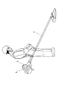
以下、本発明に係る携帯型4サイクルエンジンの好適な一実施形態について図面を参照して説明する。なお、図1は本発明の一実施形態に係る携帯型4サイクルエンジンの一使用例を説明するための図、図2は本発明の一実施形態に係る携帯型4サイクルエンジンの外観を示す斜視図、図3は本発明の一実施形態に係る携帯型4サイクルエンジンの上面図、図4は図3のA−A線断面図、図5は図4のG−G線断面図である。 Hereinafter, a preferred embodiment of a portable four-cycle engine according to the present invention will be described with reference to the drawings. FIG. 1 is a diagram for explaining an example of use of a portable four-cycle engine according to an embodiment of the present invention, and FIG. 2 is a perspective view showing an appearance of the portable four-cycle engine according to an embodiment of the present invention. 3 is a top view of a portable four-cycle engine according to an embodiment of the present invention, FIG. 4 is a cross-sectional view taken along line AA in FIG. 3, and FIG. 5 is a cross-sectional view taken along line GG in FIG.
図1に示すように、本実施形態に係る携帯型4サイクルエンジン2はエンジンカバー3に被覆され、例えば刈払機等の携帯型作業機1の駆動部に取付けられて動力源として使用される。携帯して作業を行うものであるため、動力源としての4サイクルエンジン2には小型、軽量で高出力のものが望まれている。
As shown in FIG. 1, a portable four-
図2は本実施形態に係る携帯型4サイクルエンジン2の外観を示す斜視図であり、図3は図2の上面図である。図2及び図3において、4サイクルエンジン2の側面には、キャブレター16とマフラー18が取付けられている。クランク軸5を回転自在に支承するクランクケース4の上部には、例えばアルミニウム合金をダイカスト成型して一体的に形成されたシリンダ8が配置されている。シリンダ8の上部には、シリンダ8と同様にアルミニウム合金等をダイカスト成型して作製したシリンダヘッド10が載置され、このシリンダヘッド10に形成された4箇所のボルト座10cにボルト13を挿通してシリンダ8とシリンダヘッド10が堅固に締着されている。
FIG. 2 is a perspective view showing an appearance of the portable four-
図示しない燃料タンクから供給されるガソリン等の燃料は、キャブレター16で霧化され、吸気ポート10eを通じて後述する燃焼室15(図5参照)に送られる。吸気行程で吸気バルブ20(図5参照)が開弁して燃焼室15に気化した燃料が送られ、圧縮行程、膨張行程及び排気行程の4つの行程を繰り返す。排気行程では排気バルブ12(図5参照)が開弁し、燃焼室15から排気ガスが排気ポート10fを通じてマフラー18に送られ、外部に排出される。
Fuel such as gasoline supplied from a fuel tank (not shown) is atomized by the
シリンダヘッド10の上部には、吸気ポート10eと排気ポート10fが対向して一体的に形成されている。吸気ポート10eの一端は、シリンダヘッド10の略中央部でシリンダヘッド10の下面に形成された後述する燃焼室15(図5参照)に連通しており、他端はヒートインシュレータを介してキャブレター16に接続されている。排気ポート10fも一端が燃焼室15に連通しており、他端はマフラー18に接続されている。
An
吸気ポート10e及び排気ポート10fの上部には、後述する吸気バルブ20、排気バルブ12、プッシュロッド11その他の動弁系部材を収容する動弁系収容室10gが、一対のバルブガイドボス10f2を介してそれぞれ吸気ポート10e及び排気ポート10fに接続して一体的に形成されている。動弁系収容室10gの上部はロッカーカバー9で閉塞されている。
Above the
図2中符号10g2は、吸気ポート10e、排気ポート10f、バルブガイドボス10f2及び動弁系収容室10gによって形成された開口を示し、この開口10g2はクランク軸5に取付けられたファン6からの冷却風の流通路となっている。図3中矢線19は冷却風の流れを示し、開口10g2は、風上側から風下側へ行くに従ってその断面積が小さくなるような形状に形成されているので、開口10g2の風上側の広い間口から送入した冷却風は風下側でその流速を増し、シリンダヘッド10の冷却効果が向上する。
Reference numeral 10g2 in FIG. 2 indicates an opening formed by the
シリンダヘッド10の上部には多数の縦フィン10d1、10d2、10d3、10d4が一体的に形成されている。これらの縦フィン10d1、10d2、10d3、10d4は、冷却風を効率よく導風してシリンダヘッド10の冷却効果を向上させる機能を果たすとともに、シリンダヘッド10及びこのシリンダヘッド10に一体的に形成されている吸気ポート10e、排気ポート10f、バルブガイドボス10f2、動弁系収容室10gの剛性を高める機能を果たしている。
A number of
本実施形態においては、開口10g2近傍の風上側に点火プラグ14が配置されており、点火プラグ14を挟むように縦フィン10d2と10d3が形成されている。縦フィン10d3は、バルブガイドボス10f2及び動弁系収容室10gと結合され、バルブガイドボス10f2との結合部分は、バルブガイドボス10f2の中心部から離間したバルブガイドボス10f2のクランク軸方向と直交する方向の外側端部で結合されている。このように構成することにより、風上側から流れる冷却風は点火プラグ14で分流するが、縦フィン10d2、10d3によって分散することなくバルブガイドボス10f2の外周を効率的に冷却し、開口10g2で合流して吸気ポート10e及び排気ポート10fの外周を冷却する。
In the present embodiment, the
開口10g2は風上側で広く冷却風を取り込み、開口の風下側は先細りとなっているので合流した冷却風は流速を増し、バルブガイドボス10f2周辺の冷却効率が高まる。特に排気ポート10fにおけるバルブガイド12b(図4参照)付近は、燃焼室15(図4参照)から直接排気ガスが通過するので温度が高まり易い。このため、高温となるバルブガイド12b付近を効率よく冷却することで、シリンダヘッド10全体をバランスよく冷却することが可能となる。
The opening 10g2 takes in the cooling air widely on the windward side, and the leeward side of the opening is tapered, so the combined cooling air increases the flow velocity, and the cooling efficiency around the valve guide boss 10f2 increases. In particular, in the vicinity of the
図3中符号10hは、シリンダ8の中心軸線8a(図4参照)と交わる位置に描いたクランク軸5方向と直交する方向の仮想線を示し、符号10e1及び10f1は、それぞれ吸気ポート10e及び排気ポート10fの中心軸線の位置を示す仮想線である。本実施形態では、吸気ポート10e及び排気ポート10fの中心軸線をシリンダ8の中心軸線の位置よりも風下側に設定している。これにより、シリンダヘッド10上の風上側の面積を広く確保することができ、この広く確保された風上側に多数の縦フィン10d1、10d2、10d3、10d4を配置することができる。本実施形態では、動弁系収容室10gのクランク軸5方向と直交する方向の両端部に縦フィン10d1、10d2を結合している。これにより、動弁系収容室10gの剛性を高めることができる。本実施形態によれば、冷却性能に優れ、剛性を高めつつ、小型、軽量化されたシリンダヘッド10が構成される。
In FIG. 3, reference numeral 10h indicates a virtual line drawn in a direction perpendicular to the direction of the
図4は図3のA−A線断面の要部を示す要部断面図であり、排気バルブ12及びプッシュロッド11が位置している部位の断面を示している。図5は図4のG−G線断面の要部を示す要部断面図であり、吸気バルブ20及び排気バルブ12が位置している部位の断面を示している。
FIG. 4 is a cross-sectional view of the main part showing the main part of the cross section taken along the line AA of FIG. 3, and shows a cross section of the portion where the
図4及び図5において、排気ポート10fと動弁系収容室10gを接続するように一体的に形成されたバルブガイドボス10f2には円筒状のバルブガイド12bが保持されている。排気バルブ12は、そのバルブステム12aが摺動可能にバルブガイド12bに支持されており、クランク軸5の回転と連動してプッシュロッド11によって駆動され開閉動作を行う。なお、図4及び図5において、符号17はシリンダ8の内部を上下方向に往復動作するピストンを示す。
4 and 5, a
エンジン駆動系の潤滑は、例えば特開平10−288019号公報等に開示されているように、図示しないオイルタンクからクランクケース4内部のクランク室内の圧力変化を利用してオイルがクランク室内に送られ、クランク室内でオイルは霧化する。霧化したオイルはプッシュロッドガイド10g3へ送られ、動弁系収容室10g内部の吸気バルブ20及び排気バルブ12を潤滑した後オイルタンクへ戻されて循環し、各部位の動作を円滑にする。
For example, as disclosed in Japanese Patent Application Laid-Open No. 10-288019, the engine drive system is lubricated by supplying oil from an oil tank (not shown) into the crank chamber using a pressure change in the crank chamber inside the crankcase 4. The oil atomizes in the crank chamber. The atomized oil is sent to the push rod guide 10g3, lubricates the
本実施形態では、動弁系収容室10gの底部10g1は、点火プラグ14が配置されている風上側から風下側に向けて下方に傾斜した形状に形成されている。また動弁系収容室10gの風下側には、プッシュロッド11を収容する収容孔を備えたプッシュロッドガイド10g3が下方に連通して一体的に形成されている。このように構成することにより、動弁系収容室10g内で液化した潤滑オイルが動弁系収容室10g内の底部10g1を流下してプッシュロッドガイド10g3に回収され、必要以上に動弁系収容室10g内に潤滑オイルが滞留することを防止することができる。図示はしないが、動弁系収容室10gはブリーザ機構を備え、ブローバイガスを吸気系に戻すように構成されている。動弁系収容室10g内に必要以上に液化オイルが滞留すると、外部にオイルを排出し必要以上のオイルを消費してエンジン駆動系の潤滑不良を引き起こす場合があるが、本実施形態に係る構成により、必要以上のオイル消費を抑制することができる。
In the present embodiment, the bottom 10g1 of the valve
一方、動弁系収容室10g外周部の底部10g1は冷却風を開口10g2へ導く導風構造の一部を形成するので、動弁系収容室10g周辺の冷却効果を向上させることができる。上述したように本実施形態においては、高温となる排気バルブ12付近が効率的に冷却されるので、バルブガイドボス10f2やバルブガイド12bの温度上昇によりバルブガイドボス10f2とバルブガイド12bの固着力が低下したり、バルブガイド12bの変形によるバルブステム12aの摺動不良を惹起したりという不具合を防止することができる。
On the other hand, the bottom 10g1 of the outer periphery of the valve
本実施形態では、高出力を得るために燃焼室15形状をウェッジ型に形成している。このような燃焼室形状はシリンダ8とシリンダヘッド10を分離する構造とすることで、理想的な形状を実現することができる。更に点火プラグ14を燃焼室15の深い側に配置することによって、高圧縮比が可能となるなど、より理想的な燃焼室形状を設計可能となりエンジン出力を向上させることができる。
In this embodiment, the
本実施形態において、吸気ポート10e、排気ポート10f及び幾つかの縦フィン10d1等を、シリンダ8とシリンダヘッド10との理想的な締着状態が得られるボルト座10cの近傍に配置している。この構造により、シリンダヘッド10におけるボルト座10c近傍の剛性が高まり、結合面の変形を効果的に抑え、シリンダ8とシリンダヘッド10との結合面10bの面圧を高く確保できる携帯型4サイクルエンジン2を提供することができる。
In the present embodiment, the
以上説明したように本発明によれば、従来に比べて大型化、重量化をすることなく、より高出力の携帯型4サイクルエンジン2を得ることができる。なお、本実施形態ではシリンダ8とシリンダヘッド10が分離可能な構造について説明したが、本発明は、シリンダ8とシリンダヘッド10が一体型の構造に適用しても十分に効果を得られるものである。
As described above, according to the present invention, a portable four-
本発明に係る携帯型4サイクルエンジンは、刈払機に限らず、例えばチェーンソー、ハンドヘルドブロア、背負い式ブロワ等の携帯型作業機に適用することができる。 The portable four-cycle engine according to the present invention is not limited to a brush cutter, and can be applied to portable working machines such as a chain saw, a handheld blower, and a shoulder blower.
1…携帯型作業機
2…携帯型4サイクルエンジン
3…エンジンカバー
4…クランクケース
5…クランク軸
6…ファン
8…シリンダ
8a…シリンダ中心軸線
9…ロッカーカバー
10…シリンダヘッド
10b…結合面
10c…ボルト座
10d1、10d2、10d3、10d4…縦フィン
10e…吸気ポート
10e1…吸気ポート中心軸線
10f…排気ポート
10f1…排気ポート中心軸線
10f2…バルブガイドボス
10g…動弁系収容室
10g1…底部
10g2…開口
10g3…プッシュロッドガイド
10h…シリンダ中心軸線と直交する仮想線
11…プッシュロッド
12…排気バルブ
12a…バルブステム
12b…バルブガイド
13…ボルト
14…点火プラグ
15…燃焼室
16…キャブレター
17…ピストン
18…マフラー
19…冷却風の流れ
20…吸気バルブ
DESCRIPTION OF SYMBOLS 1 ...
Claims (2)
前記クランク軸に取付けられ、前記冷却風を前記シリンダヘッドに導風するファンと、
前記クランク軸方向と直交する方向に対向して形成された吸気ポート及び排気ポートと、
前記吸気ポート及び前記排気ポートと連通して形成された燃焼室と、
前記吸気ポート及び前記排気ポートの上部に形成された動弁系収容室と、
前記動弁系収容室と前記吸気ポート及び前記排気ポートを接続し、それぞれに吸気バルブ及び排気バルブが挿通される一対のバルブガイドボスと、
前記シリンダヘッドから上方に突出し前記クランク軸方向に延伸する複数の縦フィンと、を備え、
前記吸気ポート、前記排気ポート、前記燃焼室、前記動弁系収容室、前記一対のバルブガイドボス及び複数の前記縦フィンが、前記シリンダヘッドに一体成型され、
前記シリンダヘッドにおいて、前記吸気ポート、前記排気ポート、前記バルブガイドボス及び前記動弁系収容室の底部により前記冷却風が流通する開口が形成され、
前記動弁系収容室の前記冷却風の風下側にプッシュロッドガイドが形成され、
前記動弁系収容室の底部は、前記冷却風の風上側から前記プッシュロッドガイド側にかけて下方に傾斜して形成されると共に、前記開口は、前記冷却風の風上側より風下側の断面積が小となる形状に形成され、
前記縦フィンは前記動弁系収容室と結合されると共に、前記吸気ポート及び前記排気ポートから風上側にそれぞれ延伸して形成されてなることを特徴とする携帯型4サイクルエンジン。 A portable four-cycle engine in which cooling air flows in the direction of the crankshaft with respect to the cylinder head at the top of the cylinder,
A fan attached to the crankshaft for guiding the cooling air to the cylinder head;
An intake port and an exhaust port formed facing each other in a direction orthogonal to the crankshaft direction;
A combustion chamber formed in communication with the intake port and the exhaust port;
A valve system accommodating chamber formed above the intake port and the exhaust port;
A pair of valve guide bosses connected to the valve system accommodating chamber and the intake port and the exhaust port, through which the intake valve and the exhaust valve are inserted, respectively;
A plurality of vertical fins protruding upward from the cylinder head and extending in the crankshaft direction,
The intake port, the exhaust port, the combustion chamber, the valve train accommodating chamber, the pair of valve guide bosses and the plurality of vertical fins are integrally molded with the cylinder head,
In the cylinder head, an opening through which the cooling air flows is formed by the intake port, the exhaust port, the valve guide boss, and the bottom of the valve train storage chamber,
A push rod guide is formed on the leeward side of the cooling air in the valve train accommodating chamber,
The bottom part of the valve train accommodating chamber is formed to be inclined downward from the windward side of the cooling air to the push rod guide side, and the opening has a cross-sectional area on the leeward side from the windward side of the cooling air. Formed into a small shape,
The vertical fins portable four-stroke engines, characterized by comprising formed by extending each together when combined with the valve train accommodating chamber, from the intake port and the exhaust port on the windward side.
Priority Applications (2)
| Application Number | Priority Date | Filing Date | Title |
|---|---|---|---|
| JP2006012876A JP4422110B2 (en) | 2006-01-20 | 2006-01-20 | Portable 4-cycle engine |
| US11/510,808 US7341027B2 (en) | 2006-01-20 | 2006-08-28 | Portable 4-cycle engine and portable machine equipped with the 4-cycle engine |
Applications Claiming Priority (1)
| Application Number | Priority Date | Filing Date | Title |
|---|---|---|---|
| JP2006012876A JP4422110B2 (en) | 2006-01-20 | 2006-01-20 | Portable 4-cycle engine |
Publications (2)
| Publication Number | Publication Date |
|---|---|
| JP2007192177A JP2007192177A (en) | 2007-08-02 |
| JP4422110B2 true JP4422110B2 (en) | 2010-02-24 |
Family
ID=38448067
Family Applications (1)
| Application Number | Title | Priority Date | Filing Date |
|---|---|---|---|
| JP2006012876A Expired - Fee Related JP4422110B2 (en) | 2006-01-20 | 2006-01-20 | Portable 4-cycle engine |
Country Status (1)
| Country | Link |
|---|---|
| JP (1) | JP4422110B2 (en) |
Families Citing this family (1)
| Publication number | Priority date | Publication date | Assignee | Title |
|---|---|---|---|---|
| JP2013189948A (en) * | 2012-03-15 | 2013-09-26 | Hitachi Koki Co Ltd | Engine and engine working machine |
-
2006
- 2006-01-20 JP JP2006012876A patent/JP4422110B2/en not_active Expired - Fee Related
Also Published As
| Publication number | Publication date |
|---|---|
| JP2007192177A (en) | 2007-08-02 |
Similar Documents
| Publication | Publication Date | Title |
|---|---|---|
| US7341027B2 (en) | Portable 4-cycle engine and portable machine equipped with the 4-cycle engine | |
| JP5426134B2 (en) | Saddle riding vehicle | |
| US6990932B2 (en) | Motorcycle lubrication oil cooling system | |
| JP6476796B2 (en) | Oil passage structure for cooling of multi-cylinder engines | |
| JP2006328994A (en) | Two-cycle internal combustion engine | |
| JP2016176443A (en) | Cooling water passage structure for internal combustion engine | |
| JP4391469B2 (en) | 2-cycle engine | |
| JP6565526B2 (en) | Engine oil passage structure | |
| JP4422110B2 (en) | Portable 4-cycle engine | |
| JP4636551B2 (en) | Backpack type air blower equipped with 4-cycle engine | |
| US8770157B2 (en) | Cylinder cooling apparatus for air-cooled engine | |
| JP4676319B2 (en) | 2-cycle engine | |
| JP6888430B2 (en) | Engine cooling oil passage structure | |
| US6484701B1 (en) | Four-stroke cycle internal combustion engine | |
| JP5668471B2 (en) | Air-cooled engine | |
| JP6572805B2 (en) | Engine oil passage structure | |
| US8439157B2 (en) | Engine | |
| JP5527140B2 (en) | Engine and engine working machine equipped with the same | |
| JP6897347B2 (en) | Engine cooling oil passage structure | |
| US6161509A (en) | Cylinder | |
| JP4605607B2 (en) | Cooling water passage structure for water-cooled engine | |
| JP2017180102A (en) | Power unit | |
| JPH08260960A (en) | Cooling device for engine cylinder | |
| US8943797B2 (en) | Cylinder head with symmetric intake and exhaust passages | |
| JPS6388214A (en) | Forced air-cooled vertical engine |
Legal Events
| Date | Code | Title | Description |
|---|---|---|---|
| A621 | Written request for application examination |
Free format text: JAPANESE INTERMEDIATE CODE: A621 Effective date: 20071126 |
|
| A977 | Report on retrieval |
Free format text: JAPANESE INTERMEDIATE CODE: A971007 Effective date: 20090618 |
|
| A131 | Notification of reasons for refusal |
Free format text: JAPANESE INTERMEDIATE CODE: A131 Effective date: 20090630 |
|
| A521 | Written amendment |
Free format text: JAPANESE INTERMEDIATE CODE: A523 Effective date: 20090805 |
|
| A131 | Notification of reasons for refusal |
Free format text: JAPANESE INTERMEDIATE CODE: A131 Effective date: 20091030 |
|
| A521 | Written amendment |
Free format text: JAPANESE INTERMEDIATE CODE: A523 Effective date: 20091104 |
|
| TRDD | Decision of grant or rejection written | ||
| A01 | Written decision to grant a patent or to grant a registration (utility model) |
Free format text: JAPANESE INTERMEDIATE CODE: A01 Effective date: 20091127 |
|
| A01 | Written decision to grant a patent or to grant a registration (utility model) |
Free format text: JAPANESE INTERMEDIATE CODE: A01 |
|
| A61 | First payment of annual fees (during grant procedure) |
Free format text: JAPANESE INTERMEDIATE CODE: A61 Effective date: 20091203 |
|
| FPAY | Renewal fee payment (event date is renewal date of database) |
Free format text: PAYMENT UNTIL: 20121211 Year of fee payment: 3 |
|
| R150 | Certificate of patent or registration of utility model |
Free format text: JAPANESE INTERMEDIATE CODE: R150 |
|
| FPAY | Renewal fee payment (event date is renewal date of database) |
Free format text: PAYMENT UNTIL: 20131211 Year of fee payment: 4 |
|
| S111 | Request for change of ownership or part of ownership |
Free format text: JAPANESE INTERMEDIATE CODE: R313111 |
|
| R350 | Written notification of registration of transfer |
Free format text: JAPANESE INTERMEDIATE CODE: R350 |
|
| LAPS | Cancellation because of no payment of annual fees |