JP4417068B2 - How to stop the fuel cell - Google Patents
How to stop the fuel cell Download PDFInfo
- Publication number
- JP4417068B2 JP4417068B2 JP2003347194A JP2003347194A JP4417068B2 JP 4417068 B2 JP4417068 B2 JP 4417068B2 JP 2003347194 A JP2003347194 A JP 2003347194A JP 2003347194 A JP2003347194 A JP 2003347194A JP 4417068 B2 JP4417068 B2 JP 4417068B2
- Authority
- JP
- Japan
- Prior art keywords
- hydrogen
- fuel cell
- air
- anode electrode
- discharged
- Prior art date
- Legal status (The legal status is an assumption and is not a legal conclusion. Google has not performed a legal analysis and makes no representation as to the accuracy of the status listed.)
- Expired - Fee Related
Links
- 239000000446 fuel Substances 0.000 title claims description 68
- 239000001257 hydrogen Substances 0.000 claims description 119
- 229910052739 hydrogen Inorganic materials 0.000 claims description 119
- UFHFLCQGNIYNRP-UHFFFAOYSA-N Hydrogen Chemical compound [H][H] UFHFLCQGNIYNRP-UHFFFAOYSA-N 0.000 claims description 100
- XLYOFNOQVPJJNP-UHFFFAOYSA-N water Substances O XLYOFNOQVPJJNP-UHFFFAOYSA-N 0.000 claims description 41
- 238000000034 method Methods 0.000 claims description 30
- 238000010926 purge Methods 0.000 claims description 25
- 239000007789 gas Substances 0.000 claims description 22
- 150000002431 hydrogen Chemical class 0.000 claims description 22
- 238000007599 discharging Methods 0.000 claims description 8
- QVGXLLKOCUKJST-UHFFFAOYSA-N atomic oxygen Chemical compound [O] QVGXLLKOCUKJST-UHFFFAOYSA-N 0.000 claims description 7
- 239000001301 oxygen Substances 0.000 claims description 7
- 229910052760 oxygen Inorganic materials 0.000 claims description 7
- 238000003487 electrochemical reaction Methods 0.000 claims description 4
- 230000005611 electricity Effects 0.000 claims description 2
- 208000028659 discharge Diseases 0.000 description 24
- 238000010790 dilution Methods 0.000 description 12
- 239000012895 dilution Substances 0.000 description 12
- IJGRMHOSHXDMSA-UHFFFAOYSA-N Atomic nitrogen Chemical compound N#N IJGRMHOSHXDMSA-UHFFFAOYSA-N 0.000 description 8
- 238000010248 power generation Methods 0.000 description 7
- 239000012528 membrane Substances 0.000 description 6
- 239000007787 solid Substances 0.000 description 6
- 230000000694 effects Effects 0.000 description 5
- 230000014759 maintenance of location Effects 0.000 description 5
- 238000010586 diagram Methods 0.000 description 4
- 238000002485 combustion reaction Methods 0.000 description 3
- 239000003792 electrolyte Substances 0.000 description 3
- 239000003014 ion exchange membrane Substances 0.000 description 3
- 229910052757 nitrogen Inorganic materials 0.000 description 3
- 229920000642 polymer Polymers 0.000 description 3
- 239000005518 polymer electrolyte Substances 0.000 description 3
- 239000012495 reaction gas Substances 0.000 description 3
- 230000007423 decrease Effects 0.000 description 2
- 238000001514 detection method Methods 0.000 description 2
- 229910001873 dinitrogen Inorganic materials 0.000 description 2
- 238000001035 drying Methods 0.000 description 2
- 239000002184 metal Substances 0.000 description 2
- 238000006555 catalytic reaction Methods 0.000 description 1
- 239000000919 ceramic Substances 0.000 description 1
- 238000006243 chemical reaction Methods 0.000 description 1
- 238000005516 engineering process Methods 0.000 description 1
- 239000012530 fluid Substances 0.000 description 1
- 230000008014 freezing Effects 0.000 description 1
- 238000007710 freezing Methods 0.000 description 1
- 238000010438 heat treatment Methods 0.000 description 1
- -1 hydrogen ions Chemical class 0.000 description 1
- 239000011261 inert gas Substances 0.000 description 1
- 238000005192 partition Methods 0.000 description 1
- 238000004080 punching Methods 0.000 description 1
Images


Classifications
-
- H—ELECTRICITY
- H01—ELECTRIC ELEMENTS
- H01M—PROCESSES OR MEANS, e.g. BATTERIES, FOR THE DIRECT CONVERSION OF CHEMICAL ENERGY INTO ELECTRICAL ENERGY
- H01M8/00—Fuel cells; Manufacture thereof
- H01M8/04—Auxiliary arrangements, e.g. for control of pressure or for circulation of fluids
- H01M8/04223—Auxiliary arrangements, e.g. for control of pressure or for circulation of fluids during start-up or shut-down; Depolarisation or activation, e.g. purging; Means for short-circuiting defective fuel cells
- H01M8/04231—Purging of the reactants
-
- H—ELECTRICITY
- H01—ELECTRIC ELEMENTS
- H01M—PROCESSES OR MEANS, e.g. BATTERIES, FOR THE DIRECT CONVERSION OF CHEMICAL ENERGY INTO ELECTRICAL ENERGY
- H01M8/00—Fuel cells; Manufacture thereof
- H01M8/04—Auxiliary arrangements, e.g. for control of pressure or for circulation of fluids
- H01M8/04298—Processes for controlling fuel cells or fuel cell systems
- H01M8/043—Processes for controlling fuel cells or fuel cell systems applied during specific periods
- H01M8/04303—Processes for controlling fuel cells or fuel cell systems applied during specific periods applied during shut-down
-
- Y—GENERAL TAGGING OF NEW TECHNOLOGICAL DEVELOPMENTS; GENERAL TAGGING OF CROSS-SECTIONAL TECHNOLOGIES SPANNING OVER SEVERAL SECTIONS OF THE IPC; TECHNICAL SUBJECTS COVERED BY FORMER USPC CROSS-REFERENCE ART COLLECTIONS [XRACs] AND DIGESTS
- Y02—TECHNOLOGIES OR APPLICATIONS FOR MITIGATION OR ADAPTATION AGAINST CLIMATE CHANGE
- Y02E—REDUCTION OF GREENHOUSE GAS [GHG] EMISSIONS, RELATED TO ENERGY GENERATION, TRANSMISSION OR DISTRIBUTION
- Y02E60/00—Enabling technologies; Technologies with a potential or indirect contribution to GHG emissions mitigation
- Y02E60/30—Hydrogen technology
- Y02E60/50—Fuel cells
Landscapes
- Life Sciences & Earth Sciences (AREA)
- Engineering & Computer Science (AREA)
- Manufacturing & Machinery (AREA)
- Sustainable Development (AREA)
- Sustainable Energy (AREA)
- Chemical & Material Sciences (AREA)
- Chemical Kinetics & Catalysis (AREA)
- Electrochemistry (AREA)
- General Chemical & Material Sciences (AREA)
- Fuel Cell (AREA)
Description
本発明は、低温起動に対応可能な燃料電池の停止方法に関するものである。 The present invention relates to a method of stopping a fuel cell that can cope with low-temperature startup.
近年、車両の駆動源として燃料電池を備えた燃料電池車両が提案されている。この種の燃料電池としては、アノード極とカソード極との間に電解質膜を介装した単位セルを所定数積層された構造をとるものが知られている。そして、アノード極に水素を、カソード極に空気(酸素)をそれぞれ導入することで、水素と酸素との電気化学反応によって発電して、水を生成する。燃料電池の運転中において、生成水は主にカソード極にて生成されるものの、カソード極とアノード極との間に介装した電解質膜を介して、カソード極中の水分がアノード極に移動する場合がある。また、反応ガス(水素と酸素)は前述した電解質膜中の乾燥を防止するため、加湿されている。
燃料電池の発電を停止する際には燃料電池のガス流路内には前述した生成水や加湿水が残留しており、この残留水を放置したまま発電を停止すると、低温時に残留水が凍結してしまい反応ガス(水素、空気)の供給排出の妨げとなるため、低温始動性が低下してしまう。
これに対し、特許文献1には、低温始動時の方法として、燃料電池から外部電気回路に電流を供給することで発熱させることにより、燃料電池を加熱する技術が提案されている。さらに、低温始動性を向上させるために本従来技術では、燃料電池の停止時において、燃料電池内のガス流路に残留している生成水を窒素ガスなどによって排出することで、停止期間中にガス流路内の水が凍結しないような技術が開示されている。
When the power generation of the fuel cell is stopped, the generated water or humidified water remains in the gas flow path of the fuel cell. If the power generation is stopped while leaving this residual water, the residual water is frozen at low temperatures. Therefore, the supply and discharge of the reaction gas (hydrogen, air) is hindered, so that the low temperature startability is deteriorated.
On the other hand, Patent Document 1 proposes a technique for heating a fuel cell by generating heat by supplying a current from the fuel cell to an external electric circuit as a method for starting at a low temperature. Furthermore, in order to improve the low temperature startability, in this prior art, when the fuel cell is stopped, the generated water remaining in the gas flow path in the fuel cell is discharged by nitrogen gas, etc. A technique for preventing water in the gas flow path from freezing is disclosed.
しかしながら、従来の技術においては、燃料電池のガス流路内の残留水を排出することで低温始動性を向上させているものの、窒素ガスによって燃料電池のガス流路内の残留水を排出していることから、専用の窒素ボンベなどのタンクを備えておく必要があり、燃料電池車両の車両搭載性の関係から適していないという課題があった。
さらに、燃料電池へ供給する反応ガス(水素および空気などの酸化剤)を停止時に供給する別手法も検討されているが、アノード極の残留水を排出する際には、発電に寄与しない大量の反応ガス(この場合水素)をアノード極に投入する必要があり、水素の消費量増大が懸念されていた。
従って本発明は、燃料電池の停止時に燃料電池のガス流路内、特にアノード極のガス流路に残留している残留水を排出して始動性を向上するとともに、アノード極のガス流路に残留している残留水を排出するために必要な水素の消費量を低く抑えることができる燃料電池の停止方法を提供することを目的とする。
However, in the conventional technology, although the low temperature startability is improved by discharging the residual water in the gas flow path of the fuel cell, the residual water in the gas flow path of the fuel cell is discharged by nitrogen gas. Therefore, there is a problem that it is necessary to provide a tank such as a dedicated nitrogen cylinder, which is not suitable due to the vehicle mounting property of the fuel cell vehicle.
In addition, another method of supplying reactive gas (oxidizers such as hydrogen and air) supplied to the fuel cell at the time of stoppage is also being studied, but when discharging the residual water of the anode electrode, a large amount that does not contribute to power generation A reaction gas (in this case, hydrogen) needs to be introduced into the anode electrode, and there has been concern about an increase in hydrogen consumption.
Therefore, the present invention improves the startability by discharging residual water remaining in the gas flow passage of the fuel cell, particularly in the gas flow passage of the anode electrode when the fuel cell is stopped, and in the gas flow passage of the anode electrode. It is an object of the present invention to provide a method for stopping a fuel cell that can keep the consumption of hydrogen necessary for discharging the remaining water remaining low.
請求項1に係る発明は、水素をアノード極へ、空気をカソード極へ導入することで水素と酸素との電気化学反応によって発電する燃料電池と、未利用の水素を循環利用することが可能な水素循環流路(例えば、実施の形態における水素循環流路34)と、前記水素循環流路内のガスを排出するパージ弁(例えば、実施の形態におけるパージ弁6)とを備えた燃料電池の停止方法において、前記水素循環流路への水素供給を停止し、前記パージ弁を定期的に開弁して、前記水素循環流路内のガスを排出し、前記水素循環流路内のガス圧力が所定の圧力よりも下回ったときに前記水素循環流路へ空気を導入し、前記アノード極の残留水を排出することを特徴とする。
According to the first aspect of the present invention, it is possible to circulate and use unused hydrogen and a fuel cell that generates electricity by an electrochemical reaction between hydrogen and oxygen by introducing hydrogen into the anode and air into the cathode. A fuel cell comprising a hydrogen circulation channel (for example, the
この発明によれば、前記水素循環流路への水素供給を停止した状態で前記水素循環流路のガス圧力が所定の圧力よりも下回ったときには、前記水素循環流路内に残存する水素が十分に排出されていると判定できるので、その後に前記水素循環流路に空気を導入することにより、前記アノード極の残留水の排出効果を十分に得ることができ、水素の消費量を減らすことができる。 According to the present invention, when the gas pressure in the hydrogen circulation channel falls below a predetermined pressure with the hydrogen supply to the hydrogen circulation channel stopped, sufficient hydrogen remains in the hydrogen circulation channel. Therefore, by introducing air into the hydrogen circulation passage after that, it is possible to obtain a sufficient draining effect of the residual water in the anode electrode, thereby reducing hydrogen consumption. it can.
請求項2に係る発明は、請求項1に記載のものであって、前記カソード極へ供給している空気の一部を分岐して(例えば、実施の形態における切換流路54)前記水素循環流路へ導入することを特徴とする。
この発明によれば、前記カソード極に反応ガスである空気を供給する供給器を用いてアノード極の残留水排出処理を行うことができるので、部品点数を低減でき車両搭載性を向上することができる。また、カソード極の残留水排出処理とアノード極の残留水排出処理とを並行して行うことができるので、作業効率を高めることができる。
The invention according to a second aspect is the one according to the first aspect, wherein a part of the air supplied to the cathode electrode is branched (for example, the
According to this invention, since the residual water discharge processing of the anode electrode can be performed using the supply device that supplies the reaction electrode air to the cathode electrode, the number of parts can be reduced and the vehicle mountability can be improved. it can. Moreover, since the residual water discharge process of the cathode electrode and the residual water discharge process of the anode electrode can be performed in parallel, the working efficiency can be improved.
請求項3に係る発明は、請求項1または請求項2に記載のものであって、前記アノード極の入口側圧力と出口側圧力とを検知して(例えば、実施の形態における圧力センサ41、61)、該入口側圧力と該出口側圧力の差分が基準値以内になったときに、前記残留水の排出完了を検知することを特徴とする。
この発明によれば、前記アノード極に残留水が残存している場合には、残留水が圧力損失の原因となるため該入口側圧力と該出口側圧力の差分が基準値よりも大きくなるが、残留水が排出されたときには圧力損失の原因が除去されている。従って、前記圧力の差分が基準値以内になった場合には、前記残留水の排出が完了したと判定することができるので、検出精度を向上することができる。
The invention according to claim 3 is the one according to claim 1 or 2 , wherein the inlet side pressure and the outlet side pressure of the anode electrode are detected (for example, the
According to the present invention, when residual water remains in the anode electrode, the residual water causes pressure loss, so the difference between the inlet side pressure and the outlet side pressure is larger than the reference value. When the residual water is discharged, the cause of the pressure loss is removed. Accordingly, when the pressure difference falls within the reference value, it can be determined that the discharge of the residual water has been completed, so that the detection accuracy can be improved.
請求項4に係る発明は、請求項1から請求項3のいずれかに記載のものであって、前記
アノード極から排出される未反応水素ガスを前記カソード極から排出される空気と混合さ
せる希釈器を有することを特徴とする。
この発明によれば、前記アノード極から排出される未反応水素ガスを前記希釈器にて前
記カソード極から排出される空気と混合させることで希釈することができるので、アノー
ド極から排出される水素濃度を低く保つことができ、作業効率をさらに高めることができ
る。
The invention according to
According to the present invention, since the unreacted hydrogen gas discharged from the anode electrode can be diluted by mixing with the air discharged from the cathode electrode in the diluter, the hydrogen discharged from the anode electrode The concentration can be kept low, and the working efficiency can be further increased.
請求項1に記載した発明によれば、前記アノード極の残留水の排出効果を十分に得ることができ、水素の消費量を減らすことができる。
請求項2に記載した発明によれば、部品点数を低減でき車両搭載性を向上することができるとともに、作業効率を高めることができる。
請求項3に記載した発明によれば、前記残留水の排出完了を簡易な処理で確実に検出できるので、検出精度を向上することができる。
請求項4に記載した発明によれば、アノード極から排出される水素濃度を低く保つことができ、作業効率をさらに高めることができる。
According to the first aspect of the present invention, it is possible to sufficiently obtain the effect of discharging the residual water of the anode electrode, and to reduce the consumption of hydrogen.
According to the second aspect of the present invention, the number of parts can be reduced, the vehicle mountability can be improved, and the work efficiency can be increased.
According to the third aspect of the present invention, the completion of discharge of the residual water can be reliably detected with a simple process, so that the detection accuracy can be improved.
By the invention described in
以下、この発明に係る燃料電池の停止方法の実施の形態を図面を参照して説明する。なお、以下に説明する実施の形態は、燃料電池自動車に搭載される燃料電池の停止方法の態様である。 Embodiments of a fuel cell stopping method according to the present invention will be described below with reference to the drawings. In addition, embodiment described below is an aspect of the stop method of the fuel cell mounted in a fuel cell vehicle.
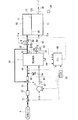
図1は、本発明の第1の実施の形態における燃料電池の停止方法が適用される燃料電池システムの概略構成図である。
燃料電池1は、例えば固体ポリマーイオン交換膜等からなる固体高分子電解質膜をアノード極とカソード極とで両側から挟み込んで形成されたセルを複数積層して構成されたスタックからなり、アノード極に燃料として水素を供給し、カソード極に酸化剤として酸素を含む空気を供給すると、アノード極で触媒反応により発生した水素イオンが、固体高分子電解質膜を通過してカソード極まで移動して、カソード極で酸素と電気化学反応を起こして発電し、水が生成される。カソード極側で生じた生成水の一部は固体高分子電解質膜を介してアノード極側に逆拡散するため、アノード極側にも生成水が存在する。
FIG. 1 is a schematic configuration diagram of a fuel cell system to which a fuel cell stopping method according to a first embodiment of the present invention is applied.
The fuel cell 1 is composed of a stack formed by stacking a plurality of cells formed by sandwiching a solid polymer electrolyte membrane made of, for example, a solid polymer ion exchange membrane between an anode electrode and a cathode electrode from both sides. When hydrogen is supplied as fuel and oxygen-containing air is supplied to the cathode electrode, hydrogen ions generated by a catalytic reaction at the anode electrode move to the cathode electrode through the solid polymer electrolyte membrane, and the cathode Water is generated by generating an electrochemical reaction with oxygen at the pole. Since part of the generated water generated on the cathode electrode side diffuses back to the anode electrode side through the solid polymer electrolyte membrane, the generated water also exists on the anode electrode side.
空気はコンプレッサ2により所定圧力に加圧され、空気供給流路31を通って燃料電池1のカソード極に供給される。空気供給流路31には図示しない加湿器などが設けられており、固体ポリマーイオン交換膜の乾燥を防止するよう加湿された空気を燃料電池に供給するように構成されている。燃料電池1に供給された空気は発電に供された後、燃料電池1からカソード極側の生成水と共に空気排出流路32に排出され、パージ水素希釈器10に導入される。また、カソード極には空気排出流路32とは別に、ドレン弁57を有したドレン流路58も接続されている。以下、燃料電池1に供給される空気を供給空気、燃料電池1から排出される空気を排出空気として区別する。
The air is pressurized to a predetermined pressure by the compressor 2 and supplied to the cathode electrode of the fuel cell 1 through the
一方、水素タンク4から供給される水素は、遮断弁51、レギュレータ52を介して水素供給流路33を通って燃料電池1のアノード極に供給される。水素も前述した空気と同様に図示しない加湿器などによって加湿されており、加湿された水素が燃料電池に供給される。そして、消費されなかった未反応の水素は、アノード極側の生成水と共にアノード極から水素循環流路34に排出され、さらにエゼクタ5を介して水素供給流路33に合流せしめられる。つまり、燃料電池1から排出された水素は、水素タンク4から供給される新鮮な水素と合流して、再び燃料電池1のアノード極に供給される。なお、エゼクタ5の代わりに水素ポンプを用いることも可能である。
水素循環流路34からは、パージ弁6を備えた水素排出流路35が分岐しており、水素排出流路35はパージ水素希釈器10に接続されている。
On the other hand, the hydrogen supplied from the
A hydrogen
パージ水素希釈器10は、隔壁13によって内部が滞留室(滞留領域)11と希釈室(希釈領域)12に区画された容器であり、滞留室11と希釈室12は通流部14によって連通されている。通流部14は、例えば小さな孔が多数設けられた金属板(いわゆる、パンチングメタル)や、多孔質セラミックスなどで構成されている。
滞留室11への入口11aには前述した水素排出流路35が接続されており、パージ弁6が開かれると、燃料電池1から排出された水素が、水素循環流路34および水素排出流路35を通って滞留室11に流入し、滞留する。
希釈室12の入口12aには前述した空気排出流路32が接続されており、燃料電池1から排出された排出空気が、空気排出流路32を通って希釈室12に流入する。希釈室12内の流体は入口12aと反対の側に設けられた出口12bから排気管36を介して排出される。したがって、燃料電池1から排出空気が排出されている時には、希釈室12には常に排出空気が通流している。
The
The above-described
The
また、空気供給流路31には空気供給流路31を通流する供給空気の流量を検出する流量センサ42が設けられ、空気排出流路32には空気排出流路32を通流する排出空気の温度を検出する温度センサ43が設けられている。また、エゼクタ5よりも下流側の水素供給流路33には水素供給流路33を通流する水素の圧力(すなわち、供給水素圧力)を検出する圧力センサ41が設けられ、水素排出流路35には水素排出流路35を通流する未反応水素ガスの圧力(すなわち、排出水素圧力)を検出する圧力センサ61が設けられている。さらに、燃料電池1には燃料電池1を構成する各セルのセル電圧を検出するセル電圧センサ44が設けられ、排気管36には排気管36を通流する水素の濃度を検出する水素濃度センサ59が設けられている。これらセンサ41〜44、61、59の出力信号や、イグニッションスイッチ60のON−OFF信号がECU40に入力される。また、カソード極と同様に、アノード極にも水素排出流路35とは別に、ドレン弁56を有したドレン流路55も接続されている。
また、上述の空気供給流路31からは、切換弁53を有した切換流路54が分岐していて、水素供給流路33にエゼクタ5の下流側で合流している。これにより、切換弁53を開くことで、水素供給流路33に空気を供給できるようにしている。
The
Further, a switching
このように構成された燃料電池システムにおいて、この実施の形態では、燃料電池1の発電状態が不調になった時に、アノード側の水分除去および窒素除去を目的として、パージ弁6を所定時間だけ開いてパージを行う。
このパージ時に、パージ弁6が開かれている間に燃料電池1から排出された水素が滞留室11に流入し、滞留室11内全体に広がっていき、パージ弁6が閉じられると水素の滞留室11への流入が停止する。一方、パージ弁6の開閉にかかわらず希釈室12には排出空気が通流しているので、滞留室11に滞留している水素は通流部14を介して希釈室12へと徐々に吸い込まれていき、希釈室12において排出空気と混合され希釈される。これにより、希釈室12の出口12bから排出されるガスの水素濃度を所定濃度よりも低くすることができ、この水素濃度の低いガスを排気管36から排出することができる。
In the fuel cell system configured as described above, in this embodiment, when the power generation state of the fuel cell 1 becomes unsatisfactory, the purge valve 6 is opened for a predetermined time for the purpose of water removal and nitrogen removal on the anode side. Purge.
During this purge, the hydrogen discharged from the fuel cell 1 flows into the staying
図2は本実施の形態における燃料電池の停止処理を示すフローチャートである。
まず、ステップS10で、イグニッションスイッチ60の停止(IG−OFF)信号がECU40に入力されると、ステップS12で遮断弁51が閉じられて、アノード極への水素の供給が停止される。
次に、ステップS14でカソード極の残留水の排出処理を開始する。このとき、パージ水素希釈器10には十分な量の空気を供給しておくことで、水素希釈器10内の水素濃度を一定以内に抑えることができる。
FIG. 2 is a flowchart showing the stop process of the fuel cell in the present embodiment.
First, when a stop (IG-OFF) signal of the
Next, in step S14, discharge processing of residual water from the cathode electrode is started. At this time, by supplying a sufficient amount of air to the
ついで、ステップS16でアノード極の減圧処理を行う。
ステップS18で、圧力センサ41で検出されたアノード極入口側の水素圧力が所定の基準圧よりも大きくなっているかの判定を行い、判定結果がYESの場合にはステップS16に戻り、判定結果がNOの場合にはステップS20に進む。
このように、前記水素循環流路34への水素供給を停止した状態で前記水素循環流路34のガス圧力が所定の圧力よりも下回ったときには、前記水素循環流路34内に残存する水素が十分に排出されていると判定できる。従って、その後に前記水素循環流路34に空気を導入することにより、前記アノード極の残留水の排出効果を十分に得ることができ、水素の消費量を減らすことができる。
この過程においては、パージ弁6を定期的に開弁することによって水素循環流路34内の水素を排出する。このとき、水素循環流路34から排出される水素はパージ水素希釈器10の滞留室11内に導入される。滞留室11内の水素は希釈室12において排出空気と混合することで希釈され、出口12bより排出される。ここで、出口12bに設けた図示しない水素濃度センサなどによって排出空気中の水素濃度が管理され、この水素濃度が所定濃度未満になるようにパージ弁6を開弁することが好ましい。
Next, the anode electrode is depressurized in step S16.
In step S18, it is determined whether the hydrogen pressure on the anode electrode inlet side detected by the
As described above, when the gas pressure in the hydrogen
In this process, the hydrogen in the
ステップS24では、切換弁53を開いて空気供給流路31に通流する空気を切換流路54を介して水素供給流路33に通流させて、アノード極に空気の供給を開始する。
ステップS26で、カソード極側の処理と同様に、まずドレン弁56を開いてドレン流路55からパージ処理を行う。ついで、パージ弁6を開いて水素排出流路35のパージ処理を行う。ステップS28で所定時間を経過したことを検知すると、ステップS30でコンプレッサ2を停止させる。そして、ステップS32で、切換弁53を閉じて切換流路54から水素供給流路33への空気の供給を停止させて、発電停止処理開始前の状態に戻す。
ステップS34で、パージ弁6を遮断してアノード極と外部とのガスの流通を遮断した状態で、処理を終了する。
In step S24, the switching
In step S26, similarly to the processing on the cathode electrode side, the
In step S34 , the process is terminated in a state where the purge valve 6 is shut off and the gas flow between the anode and the outside is shut off.
このようにして、前記アノード極を停止する際に水素の供給を停止した状態で空気をアノード極に導入することで、水素の消費を抑えつつアノード極から残留水を排出することができるので、燃料電池1の停止時に燃料電池1内の残留水を排出して始動性を向上するとともに、燃費を低く抑えることができる。 In this way, by introducing air into the anode electrode while stopping the supply of hydrogen when stopping the anode electrode, residual water can be discharged from the anode electrode while suppressing consumption of hydrogen. Residual water in the fuel cell 1 can be discharged when the fuel cell 1 is stopped to improve startability, and fuel consumption can be kept low.
また、ステップS28の処理に替えて、アノード極入口側圧力と出口側圧力をそれぞれ圧力センサ41、61で検知して、両者の差分が基準値以内となったときに残留水の排出完了を検知するようにしてもよい。このようにすると、前記水素循環流路34への水素供給を停止した状態で前記水素循環流路のガス圧力が所定の圧力よりも下回ったときには、前記水素循環流路34内に残存する水素が十分に排出されていると判定できるので、その後に前記水素循環流路34に空気を導入することにより、前記アノード極の残留水の排出効果を十分に得ることができ、水素の消費量を減らすことができる。
Further, instead of the processing in step S28, the anode electrode inlet side pressure and the outlet side pressure are detected by the
図3は本発明の第2の実施の形態における燃料電池の停止方法が適用される燃料電池システムの概略構成図である。この場合には、水素供給流路33における、切換流路54との合流点に燃焼ボックス71が介装されている点が第1の実施の形態と異なっている。このようにすると、上述の実施の形態の作用効果に加えて、前記燃料電池1を停止させる際に、前記アノード極の入口側に残留する水素を前記燃焼ボックス71で燃焼させることで不活性化させることができ、この不活性化させた状態で前記アノード極へ導入することができる。従って、前記アノード極とカソード極とで発電の発生を防止することができ、その後の残留水排出処理に速やかに移行させることができるため、作業時間の短縮化を図ることができる。さらに、不活性ガスを保持しておくために専用の窒素ボンベなどを準備する必要がなく、燃料電池車両の搭載の自由度が向上する。
FIG. 3 is a schematic configuration diagram of a fuel cell system to which the fuel cell stopping method according to the second embodiment of the present invention is applied. In this case, the point in which the combustion box 71 is interposed in the confluence | merging point with the switching
なお、本発明の内容は上述の実施の形態のみに限られるものでないことはもちろんである。例えば、燃料電池システムに加湿器を用いない構成としてもよい。また、燃料電池へ水素の供給が遮断されている状態において、アノード極中の圧力が減少するが、その減少に併せてカソード極に供給される空気の圧力を減少させてもよい。このように構成することによって、固体ポリマーイオン交換膜に対する両極の極間差圧を維持することができる。また、カソード極に供給される空気の圧力は、アノード極の圧力に応じて、且つ極間差圧が所定圧力値以内に収まるように減少させることが好ましい。 Of course, the contents of the present invention are not limited to the above-described embodiments. For example, it is good also as a structure which does not use a humidifier for a fuel cell system. Further, in the state where the supply of hydrogen to the fuel cell is interrupted, the pressure in the anode electrode decreases, but the pressure of the air supplied to the cathode electrode may be reduced in accordance with the decrease. By comprising in this way, the pole-to-electrode differential pressure | voltage with respect to a solid polymer ion exchange membrane can be maintained. Further, it is preferable that the pressure of the air supplied to the cathode electrode is reduced according to the pressure of the anode electrode so that the inter-electrode differential pressure is within a predetermined pressure value.
1 燃料電池
2 コンプレッサ
4 水素タンク
6 パージ弁
34 水素循環流路
41 圧力センサ
61 圧力センサ
71 燃焼ボックス
DESCRIPTION OF SYMBOLS 1 Fuel cell 2
Claims (4)
前記水素循環流路への水素供給を停止し、
前記パージ弁を定期的に開弁して、前記水素循環流路内のガスを排出し、
前記水素循環流路内のガス圧力が所定の圧力よりも下回ったときに前記水素循環流路へ空気を導入し、前記アノード極の残留水を排出することを特徴とする燃料電池の停止方法。 A fuel cell that generates electricity through an electrochemical reaction between hydrogen and oxygen by introducing hydrogen into the anode electrode and air into the cathode electrode, a hydrogen circulation channel capable of circulating unused hydrogen, and the hydrogen In a method for stopping a fuel cell comprising a purge valve for discharging gas in the circulation flow path,
Stop the hydrogen supply to the hydrogen circulation flow path,
Periodically opening the purge valve to discharge the gas in the hydrogen circulation flow path;
A method for stopping a fuel cell, characterized in that air is introduced into the hydrogen circulation channel and residual water in the anode electrode is discharged when the gas pressure in the hydrogen circulation channel falls below a predetermined pressure.
Priority Applications (3)
| Application Number | Priority Date | Filing Date | Title |
|---|---|---|---|
| JP2003347194A JP4417068B2 (en) | 2003-10-06 | 2003-10-06 | How to stop the fuel cell |
| US10/958,495 US7687169B2 (en) | 2003-10-06 | 2004-10-04 | Stop method for fuel cell system |
| US12/702,084 US7875399B2 (en) | 2003-10-06 | 2010-02-08 | Stop method for fuel cell system |
Applications Claiming Priority (1)
| Application Number | Priority Date | Filing Date | Title |
|---|---|---|---|
| JP2003347194A JP4417068B2 (en) | 2003-10-06 | 2003-10-06 | How to stop the fuel cell |
Publications (3)
| Publication Number | Publication Date |
|---|---|
| JP2005116269A JP2005116269A (en) | 2005-04-28 |
| JP2005116269A5 JP2005116269A5 (en) | 2006-01-12 |
| JP4417068B2 true JP4417068B2 (en) | 2010-02-17 |
Family
ID=34386395
Family Applications (1)
| Application Number | Title | Priority Date | Filing Date |
|---|---|---|---|
| JP2003347194A Expired - Fee Related JP4417068B2 (en) | 2003-10-06 | 2003-10-06 | How to stop the fuel cell |
Country Status (2)
| Country | Link |
|---|---|
| US (2) | US7687169B2 (en) |
| JP (1) | JP4417068B2 (en) |
Families Citing this family (27)
| Publication number | Priority date | Publication date | Assignee | Title |
|---|---|---|---|---|
| JP4417068B2 (en) * | 2003-10-06 | 2010-02-17 | 本田技研工業株式会社 | How to stop the fuel cell |
| JP4802476B2 (en) * | 2004-10-20 | 2011-10-26 | 株式会社エクォス・リサーチ | Fuel cell system and operation method thereof |
| JP4699010B2 (en) * | 2004-11-09 | 2011-06-08 | 本田技研工業株式会社 | Fuel cell system |
| JP4852917B2 (en) * | 2004-12-16 | 2012-01-11 | 日産自動車株式会社 | Fuel cell system |
| CA2615116C (en) * | 2005-07-14 | 2011-03-29 | Nissan Motor Co., Ltd. | Fuel cell power plant and control method thereof |
| JP4515362B2 (en) * | 2005-09-07 | 2010-07-28 | 本田技研工業株式会社 | Fuel cell vehicle and fuel cell control method |
| JP4504896B2 (en) * | 2005-10-06 | 2010-07-14 | 本田技研工業株式会社 | Fuel cell system |
| JP4872331B2 (en) | 2005-12-05 | 2012-02-08 | トヨタ自動車株式会社 | Fuel cell system and method for stopping the same |
| JP4856428B2 (en) * | 2006-01-17 | 2012-01-18 | 本田技研工業株式会社 | Fuel cell system and operation method thereof |
| JP5102448B2 (en) * | 2006-01-17 | 2012-12-19 | 本田技研工業株式会社 | Fuel cell system and operation method thereof |
| JP5118370B2 (en) * | 2007-03-27 | 2013-01-16 | 本田技研工業株式会社 | Anode scavenging system for fuel cell |
| EP2248213A1 (en) * | 2008-01-29 | 2010-11-10 | Ardica Technologies, Inc. | A system for purging non-fuel material from fuel cell anodes |
| US9034531B2 (en) * | 2008-01-29 | 2015-05-19 | Ardica Technologies, Inc. | Controller for fuel cell operation |
| JP5449680B2 (en) * | 2008-02-15 | 2014-03-19 | 本田技研工業株式会社 | Operation method of fuel cell system |
| US8808410B2 (en) | 2009-07-23 | 2014-08-19 | Intelligent Energy Limited | Hydrogen generator and product conditioning method |
| US8741004B2 (en) | 2009-07-23 | 2014-06-03 | Intelligent Energy Limited | Cartridge for controlled production of hydrogen |
| US20110053016A1 (en) * | 2009-08-25 | 2011-03-03 | Daniel Braithwaite | Method for Manufacturing and Distributing Hydrogen Storage Compositions |
| DE102009039445B4 (en) | 2009-08-31 | 2022-07-14 | Cellcentric Gmbh & Co. Kg | Process for draining liquid and/or gas |
| WO2011042932A1 (en) * | 2009-10-07 | 2011-04-14 | トヨタ自動車株式会社 | Fuel cell system and method for stopping fuel cell system |
| US8940458B2 (en) | 2010-10-20 | 2015-01-27 | Intelligent Energy Limited | Fuel supply for a fuel cell |
| WO2012058687A2 (en) | 2010-10-29 | 2012-05-03 | Ardica Technologies | Pump assembly for a fuel cell system |
| JP5722669B2 (en) * | 2011-03-04 | 2015-05-27 | 本田技研工業株式会社 | Control method of fuel cell system |
| US9169976B2 (en) | 2011-11-21 | 2015-10-27 | Ardica Technologies, Inc. | Method of manufacture of a metal hydride fuel supply |
| KR101601378B1 (en) * | 2013-12-23 | 2016-03-09 | 현대자동차주식회사 | Fuel cell management method |
| JP6225886B2 (en) * | 2014-11-14 | 2017-11-08 | トヨタ自動車株式会社 | Fuel cell system and method for discharging fluid in the system |
| JP7029630B2 (en) * | 2016-12-15 | 2022-03-04 | パナソニックIpマネジメント株式会社 | Fuel cell system |
| CN111224131B (en) * | 2020-01-16 | 2020-11-13 | 上海重塑能源科技有限公司 | Fuel cell system and low-temperature purging method thereof |
Family Cites Families (15)
| Publication number | Priority date | Publication date | Assignee | Title |
|---|---|---|---|---|
| JPS61233977A (en) | 1985-04-10 | 1986-10-18 | Fuji Electric Co Ltd | Gas replacement of fuel cell |
| JPS61233976A (en) | 1985-04-10 | 1986-10-18 | Fuji Electric Co Ltd | Fuel cell facility |
| JPS6326962A (en) | 1985-08-22 | 1988-02-04 | Tech Res & Dev Inst Of Japan Def Agency | Stop and storing method for fuel cell |
| JP2541288B2 (en) | 1988-07-06 | 1996-10-09 | 富士電機株式会社 | How to shut down the fuel cell |
| JP3509168B2 (en) | 1994-02-23 | 2004-03-22 | トヨタ自動車株式会社 | Fuel cell system |
| US5798186A (en) | 1996-06-07 | 1998-08-25 | Ballard Power Systems Inc. | Method and apparatus for commencing operation of a fuel cell electric power generation system below the freezing temperature of water |
| US6103409A (en) * | 1998-02-10 | 2000-08-15 | General Motors Corporation | Fuel cell flooding detection and correction |
| US20020076583A1 (en) * | 2000-12-20 | 2002-06-20 | Reiser Carl A. | Procedure for shutting down a fuel cell system using air purge |
| US6858336B2 (en) * | 2000-12-20 | 2005-02-22 | Utc Fuel Cells, Llc | Procedure for shutting down a fuel cell system using air purge |
| US6514635B2 (en) * | 2001-01-25 | 2003-02-04 | Utc Fuel Cells, Llc | Procedure for shutting down a fuel cell system having an anode exhaust recycle loop |
| JP2002373685A (en) | 2001-06-15 | 2002-12-26 | Toyota Motor Corp | Fuel cell system |
| JP3904191B2 (en) * | 2001-10-23 | 2007-04-11 | 本田技研工業株式会社 | Exhaust fuel diluter and exhaust fuel dilution type fuel cell system |
| JP4432312B2 (en) | 2002-08-09 | 2010-03-17 | 株式会社エクォス・リサーチ | Fuel cell device |
| JP4181390B2 (en) * | 2002-11-29 | 2008-11-12 | 本田技研工業株式会社 | Method for stopping operation of fuel cell system |
| JP4417068B2 (en) * | 2003-10-06 | 2010-02-17 | 本田技研工業株式会社 | How to stop the fuel cell |
-
2003
- 2003-10-06 JP JP2003347194A patent/JP4417068B2/en not_active Expired - Fee Related
-
2004
- 2004-10-04 US US10/958,495 patent/US7687169B2/en active Active
-
2010
- 2010-02-08 US US12/702,084 patent/US7875399B2/en not_active Expired - Fee Related
Also Published As
| Publication number | Publication date |
|---|---|
| JP2005116269A (en) | 2005-04-28 |
| US7875399B2 (en) | 2011-01-25 |
| US7687169B2 (en) | 2010-03-30 |
| US20050074641A1 (en) | 2005-04-07 |
| US20100136446A1 (en) | 2010-06-03 |
Similar Documents
| Publication | Publication Date | Title |
|---|---|---|
| JP4417068B2 (en) | How to stop the fuel cell | |
| JP4633354B2 (en) | How to stop the fuel cell | |
| JP3880898B2 (en) | Hydrogen purge control device | |
| JP2009289540A (en) | Fuel battery system, and operation method thereof | |
| JP4384395B2 (en) | Fuel cell purge hydrogen dilution system | |
| JP2007080723A (en) | Fuel cell system, and method of maintaining exhaust hydrogen concentration | |
| JP2005032652A (en) | Fuel cell system | |
| JP3893945B2 (en) | Fuel cell system | |
| JP2004193102A (en) | Fuel cell operating method, and fuel cell operating device | |
| JP2004179114A (en) | Function keeping method of fuel cell system | |
| JP2008004564A (en) | Power generation shutdown method of fuel cell system | |
| JP2008112597A (en) | Fuel cell system | |
| JP2005197156A (en) | Fuel cell system | |
| JP2010153246A (en) | Fuel cell system | |
| JP2009076261A (en) | Fuel cell system and its starting method | |
| JP2005141977A (en) | Discharging method of fuel cell system | |
| JP4757479B2 (en) | Fuel cell system | |
| JP4564347B2 (en) | Fuel cell system | |
| JP4397686B2 (en) | Fuel cell reactive gas supply device | |
| JP2006286482A (en) | Fuel cell system | |
| JP2010160935A (en) | Fuel cell system, and cathode pressure control method of fuel cell system | |
| JP2010049915A (en) | Fuel cell system and scavenging method for the same | |
| JP2006147313A (en) | Fuel cell system | |
| JP2006139939A (en) | Fuel cell system and scavenging method of fuel cell | |
| JP2010123427A (en) | Fuel cell system |
Legal Events
| Date | Code | Title | Description |
|---|---|---|---|
| A521 | Request for written amendment filed |
Free format text: JAPANESE INTERMEDIATE CODE: A523 Effective date: 20051115 |
|
| A621 | Written request for application examination |
Free format text: JAPANESE INTERMEDIATE CODE: A621 Effective date: 20051115 |
|
| A977 | Report on retrieval |
Free format text: JAPANESE INTERMEDIATE CODE: A971007 Effective date: 20080220 |
|
| A131 | Notification of reasons for refusal |
Free format text: JAPANESE INTERMEDIATE CODE: A131 Effective date: 20080226 |
|
| A521 | Request for written amendment filed |
Free format text: JAPANESE INTERMEDIATE CODE: A523 Effective date: 20080425 |
|
| A131 | Notification of reasons for refusal |
Free format text: JAPANESE INTERMEDIATE CODE: A131 Effective date: 20090915 |
|
| A521 | Request for written amendment filed |
Free format text: JAPANESE INTERMEDIATE CODE: A523 Effective date: 20091015 |
|
| TRDD | Decision of grant or rejection written | ||
| A01 | Written decision to grant a patent or to grant a registration (utility model) |
Free format text: JAPANESE INTERMEDIATE CODE: A01 Effective date: 20091117 |
|
| A01 | Written decision to grant a patent or to grant a registration (utility model) |
Free format text: JAPANESE INTERMEDIATE CODE: A01 |
|
| A61 | First payment of annual fees (during grant procedure) |
Free format text: JAPANESE INTERMEDIATE CODE: A61 Effective date: 20091125 |
|
| R150 | Certificate of patent or registration of utility model |
Ref document number: 4417068 Country of ref document: JP Free format text: JAPANESE INTERMEDIATE CODE: R150 Free format text: JAPANESE INTERMEDIATE CODE: R150 |
|
| FPAY | Renewal fee payment (event date is renewal date of database) |
Free format text: PAYMENT UNTIL: 20121204 Year of fee payment: 3 |
|
| FPAY | Renewal fee payment (event date is renewal date of database) |
Free format text: PAYMENT UNTIL: 20131204 Year of fee payment: 4 |
|
| R250 | Receipt of annual fees |
Free format text: JAPANESE INTERMEDIATE CODE: R250 |
|
| LAPS | Cancellation because of no payment of annual fees |