JP4416588B2 - Game machine - Google Patents

Game machine Download PDF

Info

Publication number
JP4416588B2
JP4416588B2 JP2004208751A JP2004208751A JP4416588B2 JP 4416588 B2 JP4416588 B2 JP 4416588B2 JP 2004208751 A JP2004208751 A JP 2004208751A JP 2004208751 A JP2004208751 A JP 2004208751A JP 4416588 B2 JP4416588 B2 JP 4416588B2
Authority
JP
Japan
Prior art keywords
ball
game
knock
start lever
ball tray
Prior art date
Legal status (The legal status is an assumption and is not a legal conclusion. Google has not performed a legal analysis and makes no representation as to the accuracy of the status listed.)
Expired - Fee Related
Application number
JP2004208751A
Other languages
Japanese (ja)
Other versions
JP2006026075A5 (en
JP2006026075A (en
Inventor
定男 井置
Original Assignee
株式会社ソフィア
Priority date (The priority date is an assumption and is not a legal conclusion. Google has not performed a legal analysis and makes no representation as to the accuracy of the date listed.)
Filing date
Publication date
Application filed by 株式会社ソフィア filed Critical 株式会社ソフィア
Priority to JP2004208751A priority Critical patent/JP4416588B2/en
Publication of JP2006026075A publication Critical patent/JP2006026075A/en
Publication of JP2006026075A5 publication Critical patent/JP2006026075A5/ja
Application granted granted Critical
Publication of JP4416588B2 publication Critical patent/JP4416588B2/en
Expired - Fee Related legal-status Critical Current
Anticipated expiration legal-status Critical

Links

Images

Landscapes

  • Slot Machines And Peripheral Devices (AREA)

Description

本発明は、遊技実行に際して球皿から複数の遊技球を取り込む球スロ式遊技機等の遊技機に関する。   The present invention relates to a gaming machine such as a ball slot type gaming machine that takes a plurality of gaming balls from a ball tray when a game is executed.

所定数の遊技球を一単位として取り込んで可変表示ゲームを行う従来の遊技機、すなわち球スロ式遊技機は、遊技球を貯留する球皿を備え、該球皿から遊技球を流下して球取込口より一度に複数の遊技球を取り込むように構成されている。そして、球スロ式遊技機の中には、球取込口の開口幅を遊技球が同時に複数個取り込める幅に設定し、該球取込口に横長なスプロケット状の送出手段を備えて、遊技球を迅速に取り込めるように構成されたものが提案されている(例えば、特許文献1参照)。
特開2002−143389号公報
A conventional gaming machine that takes a predetermined number of gaming balls as a unit and plays a variable display game, that is, a ball slot type gaming machine, includes a ball tray that stores gaming balls, and flows down the gaming balls from the ball tray. It is comprised so that a some game ball may be taken in from the taking-in port at once. In the ball slot machine, the opening width of the ball intake is set to a width that allows a plurality of game balls to be taken in at the same time, and the ball intake is provided with a horizontally long sprocket-like delivery means, There has been proposed one configured to take in a sphere quickly (see, for example, Patent Document 1).
JP 2002-143389 A

ところで、上記した球スロ式遊技機では、同時に複数の遊技球を取り込むので、遊技球を取り込んだ直後には、球皿内のうち球取込口周辺に比較的広い空間が形成され易い。この空間が形成されると、球皿内に貯留状態の遊技球は、前記した球皿内の空間に流れ込むようにして全体的に球取込口に向かって流下する。この流下中に遊技球同士のバランスが取れて互いに支持してしまうと、球皿内で所謂球詰まりが生じてしまい、遊技球が球取込口まで到達しなくなる。したがって、却って遊技球の取り込みに支障を来たすことになる。   By the way, in the above-mentioned ball slot type game machine, a plurality of game balls are taken in at the same time, so that a relatively wide space is easily formed around the ball taking-in opening in the ball tray immediately after taking in the game balls. When this space is formed, the game balls stored in the ball tray flow down toward the ball inlet as a whole into the space in the ball tray. If the game balls are balanced and supported with each other during the flow, so-called ball clogging occurs in the ball tray, and the game ball does not reach the ball inlet. Therefore, it will hinder the taking of game balls.

また、上記した球スロ式遊技機は、球皿の後側の限られた空間に幅広の球流路を確保したり、送出手段およびその駆動源を取り付けたりしなければならず、構造が複雑になってしまう。したがって、球スロ式遊技機の製造効率の向上を図り難い。   In addition, the above-mentioned ball slot machine has a complicated structure because it needs to secure a wide ball flow path in a limited space on the rear side of the ball tray, or to attach a delivery means and its drive source. Become. Therefore, it is difficult to improve the production efficiency of the ball slot machine.

そこで、本発明は、上記の事情に鑑みてなされたものであり、その目的は、簡単な構成で遊技球が球皿内に詰まる不都合を防ぎ、大量の遊技球を球皿から迅速に取り込むことができる遊技機を提供しようとするものである。   Therefore, the present invention has been made in view of the above circumstances, and the object thereof is to prevent the inconvenience that game balls are clogged in the ball tray with a simple configuration, and to quickly take in a large amount of game balls from the ball tray. It is intended to provide a gaming machine that can be used.

本発明は、上記目的を達成するために提案されたものであり、請求項1に記載のものは、前面枠に配設される球皿に遊技球を貯留し、遊技者によって選択された賭け数に応じて前記球皿から所定数の遊技球を一単位として球取込口を介して取り込み、スタートレバーの操作に基づいて可変表示ゲームを行い、前記賭け数に応じた有効ライン上に賞態様が形成されると遊技球を賞球として排出する遊技機において、
前記球皿は、遊技球を貯留する球貯留部と、該球貯留部から球取込口へ流下する遊技球を整列させる球整列部と、を備え、
前記スタートレバーは、
前記球皿の球貯留部の前方に突出した状態で配置され、遊技者が操作可能な操作部と、
該操作部から球貯留部の下方へ向けて延設された軸部と、
該軸部の中間を軸支して操作部を上下動可能とする回動軸と、
を備え、
前記球皿の周辺には、当該球皿を振動させる振動手段を設け
該振動手段は、前記スタートレバーの回動軸に接続されたリンク部と、該リンク部の端部に上方へ突出した状態で設けられ、球皿の底部裏面へ衝接可能なノック部と、を備え、
前記スタートレバーの操作に基づいて、リンク部が回動軸周りに回動し、ノック部が上昇して球皿の底部裏面に衝突して球皿を振動させるように構成されたことを特徴とする遊技機である。
The present invention has been proposed in order to achieve the above-mentioned object. According to the first aspect of the present invention, a game ball is stored in a ball tray disposed on a front frame, and a bet selected by a player is selected. Depending on the number, a predetermined number of game balls are taken as a unit from the ball tray through the ball take-in port, a variable display game is played based on the operation of the start lever, and a prize is awarded on the active line according to the number of bets. In a gaming machine that discharges game balls as prize balls when an aspect is formed,
The ball tray includes a ball storage unit that stores game balls, and a ball alignment unit that aligns the game balls flowing down from the ball storage unit to the ball intake port,
The start lever is
An operation unit that is arranged in a protruding state in front of the ball storage unit of the ball tray and that can be operated by the player,
A shaft portion extending from the operation portion toward the lower side of the ball storage portion;
A rotating shaft that pivotally supports the middle of the shaft portion and allows the operation portion to move up and down;
With
Vibrating means for vibrating the ball dish is provided around the ball dish ,
The vibration means includes a link portion connected to the rotation shaft of the start lever, a knock portion provided in a state of protruding upward at an end portion of the link portion, and capable of striking the bottom rear surface of the ball tray, With
Based on the operation of the start lever, and wherein the link portion is rotated around the rotation axis, the knock portion is configured to vibrate the sphere dish collide risen to the bottom rear surface of the sphere dish It is a gaming machine to play.

なお、「周辺」とは、球皿へ十分な振動を伝達して球皿内の球詰まり解消を達成し得る範囲内を意味し、球皿に直接設ける場合も含む。   The term “periphery” means a range in which sufficient vibration can be transmitted to the ball tray to eliminate clogging in the ball tray, and includes a case where the ball tray is provided directly on the ball tray.

請求項2に記載のものは、前記ノック部の先端および/または前記球皿のうちノック部の先端に対向する箇所に緩衝部材を設けたことを特徴とする請求項1に記載の遊技機である。 The pump of Claim 2, in the gaming machine according to claim 1, characterized in that at a location opposite to the distal end of the knock part of the tip and / or the ball dish of the knock portion provided cushioning member is there.

請求項3に記載のものは、前記スタートレバー軸部の先端には、球貯留部の底部裏面へ衝接可能な球貯留ノック部備え、
前記スタートレバーの操作に基づいて、球貯留ノック部が球貯留部に衝突して球貯留部を振動させるように構成されたことを特徴とする請求項1に記載の遊技機である。
Those described in claim 3, the distal end of the shaft portion of the start lever is provided with abutment capable spherical reservoir knock part to the bottom rear surface of the sphere reservoir,
Based on the operation of the start lever, a gaming machine according to claim 1, spherical reservoir knock part is characterized by being configured to collide with the sphere reservoir to vibrate the sphere reservoir.

請求項4に記載のものは、前記球貯留ノック部の先端および/または前記球皿のうち球貯留ノック部の先端に対向する箇所に緩衝部材を設けたことを特徴とする請求項3に記載の遊技機である。 The pump of Claim 4, Claim 3, characterized in that a cushioning member at a location opposite the tip of the ball reservoir knock part of the tip and / or the ball dish the ball reservoir nock This is a gaming machine.

本発明によれば、以下のような優れた効果を奏する。
請求項1に記載の発明によれば、前面枠に配設される球皿に遊技球を貯留し、遊技者によって選択された賭け数に応じて球皿から所定数の遊技球を一単位として球取込口を介して取り込み、スタートレバーの操作に基づいて可変表示ゲームを行い、賭け数に応じた有効ライン上に賞態様が形成されると遊技球を賞球として排出する遊技機において、球皿は、遊技球を貯留する球貯留部と、該球貯留部から球取込口へ流下する遊技球を整列させる球整列部とを備え、スタートレバーは、球皿の球貯留部の前方に突出した状態で配置され、遊技者が操作可能な操作部と、該操作部から球貯留部の下方へ向けて延設された軸部と、該軸部の中間を軸支して操作部を上下動可能とする回動軸とを備え、球皿の周辺には、当該球皿を振動させる振動手段を設け、該振動手段は、前記スタートレバーの回動軸に接続されたリンク部と、該リンク部の端部に上方へ突出した状態で設けられ、球皿の底部裏面へ衝接可能なノック部とを備え、スタートレバーの操作に基づいて、リンク部が回動軸周りに回動し、ノック部が上昇して球皿の底部裏面に衝突して球皿を振動させるように構成したので、球皿内で遊技球が詰まる不具合を解消することができ、一度に大量の遊技球をスムーズに取り込めるようにすることもできる。また、スタートレバーを操作して今回の可変表示ゲームを行うとともに、次回の可変表示ゲームの賭けに取り込む遊技球を詰まることなく流下するように準備することができる。したがって、可変表示ゲームを連続して迅速に行うことができ、遊技の興趣を維持し易い。また、遊技球が詰まり易い箇所の周辺に直接振動を与えることができ、球皿での球詰まりを効率よく解消することができる。さらに、簡単な構成で球皿に衝撃力を与えて、球皿を揺らすことができる。したがって、球皿内で遊技球が詰まる不具合を短時間で効率よく解消することができる。
According to the present invention, the following excellent effects can be obtained.
According to the first aspect of the present invention, a game ball is stored in a ball tray disposed on the front frame, and a predetermined number of game balls are taken as one unit from the ball plate according to the number of bets selected by the player. In a gaming machine that takes in through a ball inlet, performs a variable display game based on the operation of a start lever, and discharges a game ball as a prize ball when an award form is formed on an effective line according to the number of bets, The ball tray includes a ball storage portion that stores a game ball, and a ball alignment portion that aligns the game balls flowing down from the ball storage portion to the ball inlet, and the start lever is located in front of the ball storage portion of the ball tray. An operation part which is arranged in a protruding state and can be operated by the player, a shaft part extending from the operation part toward the lower side of the ball storage part, and an operation part pivotally supported in the middle of the shaft part and a rotation shaft to be vertically movable, and the periphery of the Tamasara, vibration means for vibrating the ball dish Provided, the vibrating means includes a link connected portion to the rotation shaft of the start lever, provided so as to protrude upward on the end of the link portion, abuts possible knock part to the bottom rear surface of Tamasara Based on the operation of the start lever , the link part rotates around the rotation axis, the knock part rises and collides with the bottom rear surface of the ball dish, and the ball dish is vibrated . It is possible to solve the problem that the game balls are clogged in the ball tray, and it is possible to smoothly load a large number of game balls at once. In addition, the present variable display game is operated by operating the start lever, and it is possible to prepare to flow down without clogging the game balls to be taken in the bet of the next variable display game. Therefore, the variable display game can be performed quickly and continuously, and it is easy to maintain the interest of the game. In addition, vibration can be directly applied to the vicinity of a place where game balls are easily clogged, and ball clogging in the ball tray can be efficiently eliminated. Further, the ball tray can be shaken by applying an impact force to the ball tray with a simple configuration. Therefore, the trouble that the game ball is clogged in the ball tray can be solved efficiently in a short time.

請求項2に記載の発明によれば、ノック部の先端および/または球皿のうちノック部の先端に対向する箇所に緩衝部材を設けたので、ノック部からの衝撃力により球皿が損傷してしまう不具合や、ノック部自体が破損してしまう不具合を抑制することができる。 According to the second aspect of the present invention, since the buffer member is provided in the tip of the knock part and / or the part of the ball dish facing the tip of the knock part, the ball dish is damaged by the impact force from the knock part. Inconveniences, and the knock part itself is damaged.

請求項3に記載の発明によれば、スタートレバー軸部の先端には、球貯留部の底部裏面へ衝接可能な球貯留ノック部備え、スタートレバーの操作に基づいて、球貯留ノック部が球貯留部に衝突して球貯留部を振動させるように構成したので、簡単な構造で球貯留部に衝撃力を与えることができる。したがって、振動手段により球貯留部と球整列部との境界周辺を振動させるとともに、球貯留ノック部により球貯留部を振動させることができ、球皿での球詰まりを一層効率よく解消することができる。 According to the invention described in claim 3, the distal end of the shaft portion of the start lever, provided with abutment capable spherical reservoir knock part to the bottom rear surface of the sphere reservoir, based on the operation of the start lever, ball retention knock since part it has collided to the ball storage portion configured to vibrate the sphere reservoir can provide an impact force to the ball reservoir with a simple structure. Therefore, the vibrating means can vibrate the periphery of the boundary between the sphere reservoir and the sphere alignment portion, and the sphere reservoir can be vibrated by the sphere reservoir knocking portion, thereby eliminating the ball clogging in the ball tray more efficiently. it can.

請求項4に記載の発明によれば、球貯留ノック部の先端および/または球皿のうち球貯留ノック部の先端に対向する箇所に緩衝部材を設けたので、球貯留ノック部からの衝撃力により球皿が損傷してしまう不具合や、球貯留ノック部自体が破損してしまう不具合を抑制することができる。 According to the fourth aspect of the present invention, since the shock absorbing member is provided at the tip of the ball storage knock portion and / or the portion of the ball dish facing the tip of the ball storage knock portion, the impact force from the ball storage knock portion Therefore, it is possible to suppress a problem that the ball tray is damaged and a problem that the ball storage knock part itself is damaged.

以下、本発明の実施の最良の形態を図面に基づき説明する。図1は、本発明に係る遊技機であって遊技媒体として遊技球(パチンコ球)を使用する球スロ式遊技機1の正面図、図2は、球スロ式遊技機1の内部を説明する図である。
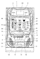
球スロ式遊技機1は、前面が開口した箱状の筐体2の内部に可変表示装置3を収納し、筐体2の前面側には前面枠4を開放(開閉)可能に取り付け(図2参照)、前面枠4の前面に縦長な開口窓部5を複数(例えば3つ)横に並べて開設し、該開口窓部5から可変表示装置3の表示部6を臨ませて複数の識別情報を可変表示可能とし、該表示部6の下方に位置する前面枠4の前面側には、左側に球排出口7を、中央部周辺に球取込口8を、球排出口7が球取込口8よりも僅かに高い位置に配置される状態でそれぞれ開設し、球皿ユニット(上皿ユニット)9を、球排出口7および球取込口8を前方から覆う状態で取り付けて、上方へ開放された球皿10を形成している。そして、球皿ユニット9には、遊技における入力操作をするための入力操作部(ベットボタン11、MAXベットボタン12、取込ボタン11′、MAX取込ボタン12′、スタートレバー13、ストップボタン14)を配設している。さらに、前面枠4の下方には、球出口15、下皿16、スピーカー17を備えた下皿ユニット18を備えている。なお、可変表示装置3は、3つの独立駆動可能なベルトタイプの単位表示ユニット20を備え、該単位表示ユニット20に掛け渡された無端ベルト21の外周面に図柄や数字等の識別情報を複数記載しており、それぞれの無端ベルト21を駆動および停止させて識別情報を可変表示できるように構成されている。
The best mode for carrying out the present invention will be described below with reference to the drawings. FIG. 1 is a front view of a ball slot machine 1 that uses a game ball (pachinko ball) as a game medium according to the present invention, and FIG. 2 illustrates the inside of the ball slot machine 1. FIG.
The ball slot machine 1 accommodates the variable display device 3 inside a box-shaped housing 2 whose front surface is open, and is attached to the front surface side of the housing 2 so that the front frame 4 can be opened (opened and closed) (see FIG. 2), a plurality of (e.g., three) vertically open window portions 5 are opened side by side on the front surface of the front frame 4, and a plurality of identifications are made by facing the display portion 6 of the variable display device 3 from the open window portions 5. The information can be variably displayed. On the front side of the front frame 4 positioned below the display unit 6, the sphere outlet 7 is on the left side, the sphere inlet 8 is around the center, and the sphere outlet 7 is a sphere. Each is opened in a state where it is arranged at a position slightly higher than the intake port 8, and a ball tray unit (upper plate unit) 9 is attached in a state of covering the ball discharge port 7 and the ball intake port 8 from the front, A ball tray 10 opened upward is formed. The ball tray unit 9 includes an input operation unit (the bet button 11, the MAX bet button 12, the capture button 11 ', the MAX capture button 12', the start lever 13, and the stop button 14 for performing an input operation in the game. ). Further, below the front frame 4, a lower plate unit 18 including a ball outlet 15, a lower plate 16, and a speaker 17 is provided. The variable display device 3 includes three belt-type unit display units 20 that can be independently driven, and a plurality of pieces of identification information such as symbols and numerals are provided on the outer peripheral surface of the endless belt 21 that is stretched over the unit display unit 20. The identification information can be variably displayed by driving and stopping each endless belt 21.

また、前面枠4は、前方をクリア板で覆い、開口窓部5の上方に液晶表示装置等からなる情報表示装置23を、左右にベットライン表示部24および遊技状態表示部(賞態様表示器25、ゲームオーバー表示器26、ウェイト表示器27、リプレイ表示器28等)を、下方に払出数表示部29、遊技進行表示部30、クレジット数表示部31をそれぞれ配設している。なお、ベットライン表示部24は、可変表示ゲームに対する賭け数に対応して有効化されたベットラインを有効ラインとして表示するものである。   Further, the front frame 4 covers the front with a clear plate, an information display device 23 composed of a liquid crystal display device or the like above the opening window portion 5, and a bet line display portion 24 and a game state display portion (award mode indicator) on the left and right. 25, a game over indicator 26, a weight indicator 27, a replay indicator 28, etc.), and a payout number display unit 29, a game progress display unit 30, and a credit number display unit 31 are arranged below. The bet line display unit 24 displays a bet line activated corresponding to the number of bets on the variable display game as an effective line.

次に、球皿ユニット9について説明する。
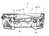
球皿ユニット9は、図3および図4に示すように、前方に膨出した状態で形成され、球皿10の前方、下方および左右両側方を覆う球皿カバー部材34と、上方及び後方を開放した上方視略半ラケット状の球皿本体35とにより概略構成されている。そして、球皿ユニット9の上部の右側には、ベットボタン11およびMAXベットボタン12を配置し、さらに、球皿ユニット9の前部には、左側にスタートレバー13を、その右隣にストップボタン14を単位表示ユニット20の位置に合わせて横方向(横並び)に列設し、さらにその右隣に、取込ボタン11′とMAX取込ボタン12′とを配置している(図1参照)。なお、スタートレバー13の構成については、後で詳細に説明する。
Next, the ball tray unit 9 will be described.
As shown in FIGS. 3 and 4, the ball tray unit 9 is formed in a state of bulging forward, and includes a ball tray cover member 34 that covers the front, lower, and left and right sides of the ball tray 10, and the upper and rear sides. It is roughly constituted by an open upper half-racket-shaped ball dish main body 35 as viewed from above. A bet button 11 and a MAX bet button 12 are arranged on the right side of the upper part of the ball tray unit 9, and a start lever 13 is placed on the left side of the front portion of the ball dish unit 9, and a stop button is located on the right side of the start lever 13. 14 are arranged in a horizontal direction (side by side) in accordance with the position of the unit display unit 20, and an acquisition button 11 'and a MAX acquisition button 12' are arranged on the right side thereof (see FIG. 1). . The configuration of the start lever 13 will be described later in detail.

球皿本体35は、球皿カバー部材34の上部の左寄りに取り付けられ、後方の開放部分を前面枠4により閉塞されることにより球皿10を形成している。この球皿10は、球スロ式遊技機1内に取り込む遊技球を一時貯留するためのものであり、図3に示すように、球排出口7に連通し、遊技球を貯留する幅広な球貯留部40と、球貯留部40と球取込口8とを連通し、球貯留部40から球取込口8へ流下する遊技球を1列に整列させる球整列部41とを備え、底面を球排出口7から球取込口8へ向けて僅かに下り傾斜させている。そして、球貯留部40のうち球整列部41と接続されている部分を、球整列部41および球取込口8へ近づくに連れて次第に狭く絞り込んだ形状に形成している。したがって、この球皿10は、球排出口7から排出された遊技球、あるいは遊技者等により当該球皿10の上方から投入された遊技球を球貯留部40に貯留し、また、貯留された遊技球を球整列部41へ流下させることで徐々に1列に整列させて球取込口8へ1個ずつ供給するように構成されている。   The ball tray main body 35 is attached to the upper left side of the upper portion of the ball dish cover member 34, and the rear open part is closed by the front frame 4 to form the ball dish 10. The ball tray 10 is for temporarily storing game balls to be taken into the ball slot game machine 1, and as shown in FIG. 3, a wide ball that communicates with the ball discharge port 7 and stores game balls. The storage unit 40, the ball storage unit 40 and the ball intake port 8 communicate with each other, and includes a ball alignment unit 41 that aligns the game balls flowing down from the ball storage unit 40 to the ball intake port 8 in one row, Is inclined slightly downward from the ball discharge port 7 toward the ball intake port 8. And the part connected with the ball | bowl alignment part 41 among the ball | bowl storage parts 40 is formed in the shape narrowed down gradually as it approaches the ball | bowl alignment part 41 and the ball | bowl intake port 8. As shown in FIG. Therefore, the ball tray 10 stores the game balls discharged from the ball discharge port 7 or the game balls thrown in from the upper side of the ball tray 10 by the player or the like in the ball storage section 40 and is stored. The game balls are caused to flow down to the ball aligning portion 41 so as to be gradually aligned in a line and supplied one by one to the ball intake port 8.

なお、球取込口8の奥側には、球取込装置43が設けられている。この球取込装置43は、一単位となる所定数(本実施形態では5個)の遊技球を取り込むためのものであり、図5に示すように、球取込流路44をケース45の内部に屈曲した状態で形成するとともに、球取込流路44の上流端を球取込口8に連通し、球取込流路44の屈曲部分には、ストッパ用ソレノイド46の駆動により可動するストッパ47を、先端が球取込流路44内に進退可能な状態で設けている。また、ストッパ47の先端に当接して停止した遊技球の2個目に対応する位置に遊技球カウントセンサ48を設け、1個目および3〜5個目に対応する位置に遊技球検出センサ49を設けてある。さらに、球取込流路44のストッパ47よりも下流側を2つに分岐し、この分岐部にはソレノイド等の駆動源50(図8参照)により切替可能な返却切替レバー51を設けている。また、分岐した流路の一方(取込用流路44a)を球スロ式遊技機1の裏側に開放し、他方(返却用流路44b)を下皿16に接続している。   A ball take-in device 43 is provided on the back side of the ball take-in port 8. The ball take-in device 43 is for taking in a predetermined number (5 in this embodiment) of game balls as one unit. As shown in FIG. In addition to being formed in a bent state, the upstream end of the sphere intake channel 44 communicates with the sphere intake port 8, and the bent portion of the sphere intake channel 44 is movable by driving a stopper solenoid 46. The stopper 47 is provided in a state where the tip can be advanced and retracted into the ball take-in channel 44. In addition, a game ball count sensor 48 is provided at a position corresponding to the second game ball stopped by contacting the tip of the stopper 47, and a game ball detection sensor 49 is provided at a position corresponding to the first and third to fifth balls. Is provided. Furthermore, the downstream side of the stopper 47 of the ball intake passage 44 is branched into two, and a return switching lever 51 that can be switched by a drive source 50 (see FIG. 8) such as a solenoid is provided at this branching portion. . Further, one of the branched channels (take-in channel 44 a) is opened to the back side of the ball slot machine 1, and the other (return channel 44 b) is connected to the lower plate 16.

したがって、遊技球カウントセンサ48および遊技球検出センサ49により一単位、すなわち5個の遊技球があるか否かを監視することができ、一単位分の遊技球があるとストッパ用ソレノイド46が励磁してストッパ47の先端が球取込流路44内から後退し、これにより球取込流路44内で停止していた遊技球が流下し、遊技球カウントセンサ48が5個目の球を検出すると、ストッパ用ソレノイド46が消磁し、5個目の遊技球が通過して6個目の遊技球が通過しないタイミングでストッパ47の先端を球取込流路44内に突入させて6個目の遊技球を停止させ、これにより一単位(5個)の遊技球を取り込むことができる。一方、遊技球検出センサ49が一単位の遊技球に満たない旨、すなわち球不足を検出すると、返却切替レバー51が切り替わって球取込流路44内の遊技球を返却用流路44bへ流下して下皿16に戻す。   Therefore, it is possible to monitor whether or not there is one unit, that is, five game balls by the game ball count sensor 48 and the game ball detection sensor 49, and when there is one unit of game ball, the stopper solenoid 46 is excited. Then, the tip of the stopper 47 is retracted from the inside of the ball take-in flow path 44, whereby the game ball stopped in the ball take-in flow path 44 flows down, and the game ball count sensor 48 removes the fifth ball. Upon detection, the stopper solenoid 46 is demagnetized, and the tip of the stopper 47 enters the ball take-in flow path 44 at the timing when the fifth game ball passes and the sixth game ball does not pass. The game ball of the eye is stopped, and thereby one unit (5) of the game balls can be taken in. On the other hand, when the game ball detection sensor 49 detects that the number of game balls is less than one unit, that is, when a shortage of balls is detected, the return switching lever 51 is switched and the game balls in the ball take-in channel 44 flow down to the return channel 44b. Return to the lower plate 16.

スタートレバー13は、可変表示装置3のベルトを回転駆動させて識別情報の可変表示をスタートさせるための可変表示始動入力操作部である。このスタートレバー13は、図6に示すように、球皿10の球貯留部40の前方に突出した状態で配置される操作部53と、該操作部53から前記球貯留部40の下方へ向けて延設された軸部54と、軸部54の球皿側端部54a(図中右側端部)を検出可能なスタートレバーセンサ55とを備え、軸部54の中間を回動軸56により軸支して操作部53が上下動できるように構成されている。このような構成を備えたスタートレバー13は、常態では、軸部54のうち回動軸56よりも球皿10側の部分がばね等の付勢部材(図示せず)により下方に付勢されて、操作部53を上へ上げるとともに、スタートレバーセンサ55が軸部54の球皿側端部54aを検出している状態になっている(図6(a)参照)。また、遊技者により操作部53が押し下げられると、軸部54の球皿側端部54aが上昇してスタートレバーセンサ55の検出状態が解除される(図6(b)参照)。そして、操作部53の押し下げ状態を解除すると元の位置まで回動し、再び押し下げ操作可能な状態に戻る。   The start lever 13 is a variable display start input operation unit for starting the variable display of the identification information by rotating the belt of the variable display device 3. As shown in FIG. 6, the start lever 13 includes an operation unit 53 that is disposed in a state of protruding in front of the ball storage unit 40 of the ball tray 10, and a downward direction from the operation unit 53 to the ball storage unit 40. And a start lever sensor 55 capable of detecting a ball tray side end portion 54a (right end portion in the figure) of the shaft portion 54, and a rotation shaft 56 between the shaft portion 54 and the shaft lever 54. The operation unit 53 can be moved up and down by pivoting. In the normal state of the start lever 13 having such a configuration, a portion of the shaft portion 54 closer to the ball tray 10 than the rotating shaft 56 is biased downward by a biasing member (not shown) such as a spring. As a result, the operating portion 53 is raised and the start lever sensor 55 is detecting the ball tray side end portion 54a of the shaft portion 54 (see FIG. 6A). Moreover, when the operation part 53 is pushed down by the player, the ball tray side end part 54a of the shaft part 54 rises and the detection state of the start lever sensor 55 is released (see FIG. 6B). Then, when the depressed state of the operation unit 53 is released, the operation unit 53 is rotated to the original position, and returns to a state where the depressing operation is possible.

さらに、球スロ式遊技機1は、球皿10のうち球貯留部40と球整列部41との境界周辺に振動手段60を設けている(図3参照)。この振動手段60は、図7に示すように、重心位置からずれた位置に軸孔を開設した円柱状の偏心部材61と、該偏心部材61の軸孔に出力軸を接続する振動モータ62(本発明の回転駆動源に相当)とにより構成され、保持部材63の内部空間に収納された状態で球皿本体35の裏側(下面)に取り付けられている。そして、振動モータ62により偏心部材61を回転すると、偏心部材61の回転中心と重心とがずれるため、偏心部材61に加わる遠心力のバランスが崩れて振動を生じ、この振動を球皿10へ伝達する。すなわち、振動手段60は、偏心部材61を回転することで球皿10を振動させるように構成されている。   Further, the ball slot machine 1 is provided with a vibrating means 60 around the boundary between the ball storage unit 40 and the ball alignment unit 41 in the ball tray 10 (see FIG. 3). As shown in FIG. 7, the vibration means 60 includes a cylindrical eccentric member 61 having a shaft hole at a position shifted from the center of gravity, and a vibration motor 62 (with an output shaft connected to the shaft hole of the eccentric member 61). And corresponds to the rotational drive source of the present invention, and is attached to the back side (lower surface) of the ball tray main body 35 in a state of being housed in the internal space of the holding member 63. When the eccentric member 61 is rotated by the vibration motor 62, the center of rotation of the eccentric member 61 and the center of gravity are displaced, so that the centrifugal force applied to the eccentric member 61 is lost and vibration is generated, and this vibration is transmitted to the ball tray 10. To do. That is, the vibration means 60 is configured to vibrate the ball tray 10 by rotating the eccentric member 61.

次に、球スロ式遊技機1の遊技制御を行う遊技制御装置65について説明する。図8は、球スロ式遊技機1に備えられる制御装置の構成図で、主として、遊技制御装置65を中心とする制御系統部分をブロック構成図として示したものである。   Next, the game control device 65 that performs the game control of the ball slot machine 1 will be described. FIG. 8 is a configuration diagram of a control device provided in the ball slot machine 1 and mainly shows a control system portion centering on the game control device 65 as a block configuration diagram.

遊技制御装置65は、遊技を統括的に制御する主制御装置として機能し、図示するように、遊技制御を司るCPU、遊技制御のためのプログラム等を記憶しているROM、および遊技制御時にワークエリアとして利用されるRAMをそれぞれ内蔵し、入力インターフェースおよび出力インターフェースを備えている。   The game control device 65 functions as a main control device that controls the game in an integrated manner, and as shown in the figure, a CPU that controls the game control, a ROM that stores a program for the game control, and a work at the time of the game control. Each RAM used as an area is built in, and an input interface and an output interface are provided.

このような構成からなる遊技制御装置65は、各種検出装置(遊技球検出センサ49、遊技球カウントセンサ48、ベルト位置検出センサ66、払い出し球検出センサ67、確率設定装置68)や各種入力装置(スタートレバーセンサ55、ストップボタン14、ベットボタン11、MAXベットボタン12、取込ボタン11′、MAX取込ボタン12′、クレジット選択スイッチ69)等からの信号を受けて、遊技進行の処理を行う。そして、各種制御装置(演出制御装置70、表示制御装置71、音制御装置72)の他、各種表示部(払出数表示部29、遊技進行表示部30、クレジット数表示部31、ベットライン表示部24、遊技状態表示部26〜28、装飾表示部74)、各種駆動源(ストッパ用ソレノイド46、返却切替レバー用駆動源50、ベルト用モータ75、振動モータ62)等に指令信号を送信して、遊技を統括的に制御する。   The game control device 65 configured as described above includes various detection devices (game ball detection sensor 49, game ball count sensor 48, belt position detection sensor 66, payout ball detection sensor 67, probability setting device 68) and various input devices ( In response to signals from the start lever sensor 55, stop button 14, bet button 11, MAX bet button 12, take-in button 11 ′, MAX take-in button 12 ′, credit selection switch 69), etc., processing of the game progress is performed. . In addition to various control devices (production control device 70, display control device 71, sound control device 72), various display units (payout number display unit 29, game progress display unit 30, credit number display unit 31, bet line display unit) 24, game state display units 26 to 28, decoration display unit 74), command signals to various drive sources (stopper solenoid 46, return switching lever drive source 50, belt motor 75, vibration motor 62), etc. , Control the game centrally.

演出制御装置70は、CPU、ROM、RAM等から構成され、表示制御装置71および音制御装置72へ制御信号を出力している。また、表示制御装置71は、CPU、ROM、RAM等から構成され、演出制御装置70からの表示制御指令信号(制御データ)に基づいて、情報表示装置23の表示を制御する。そして、音制御装置72は、CPU、ROM、RAM等から構成され、演出制御装置70を介して遊技制御装置65に接続されており、スピーカー17からの効果音出力を制御する。   The effect control device 70 includes a CPU, a ROM, a RAM, and the like, and outputs control signals to the display control device 71 and the sound control device 72. The display control device 71 includes a CPU, ROM, RAM, and the like, and controls the display of the information display device 23 based on a display control command signal (control data) from the effect control device 70. The sound control device 72 includes a CPU, a ROM, a RAM, and the like, is connected to the game control device 65 via the effect control device 70, and controls the sound effect output from the speaker 17.

次に、上記した構成を有する球スロ式遊技機1の動作、特に、上記した振動手段60の動作について説明する。なお、球スロ式遊技機1で可変表示ゲームを行うための準備として、球皿10に遊技球を貯留しておく。
まず、遊技者によりベットボタン11、MAXベットボタン12、取込ボタン11′、MAX取込ボタン12′のいずれかが押されて可変表示ゲームの賭け数(ベット数)が選択される。ベットボタン11が1回押された場合には、遊技制御装置65は、クレジット(遊技者が球スロ式遊技機1、具体的には遊技制御装置65に予納したり、あるいは遊技の結果により獲得し付与されて遊技制御装置65に記憶したりした遊技価値)から遊技球5個分の遊技価値を賭け数として設定し、ベットボタン11が2回押された場合には、クレジットから遊技球10個分の遊技価値を賭け数として設定し、ベットボタン11が3回あるいはMAXベットボタン12が押された場合には、クレジットから遊技球15個分の遊技価値を賭け数として設定する。また、取込ボタン11′が1回押された場合には、一単位である5個の遊技球の取り込み動作を1回行い、取込ボタン11′が2回押された場合には、5個の遊技球の取り込み動作を2回行って10個の遊技球を取り込み、取込ボタン11′が3回あるいはMAX取込ボタン12′が押された場合には、5個の遊技球の取り込み動作を3回行って15個(1回の可変表示ゲームに賭けられる上限数)の遊技球を取り込む。そして、遊技価値の賭け数が設定されたり、あるいは遊技球が取り込まれたりすると、遊技球の賭け数に応じた有効ラインがベットライン表示部24により表示される。
Next, the operation of the ball slot machine 1 having the above-described configuration, particularly the operation of the above-described vibration means 60 will be described. In addition, as a preparation for playing the variable display game on the ball slot machine 1, game balls are stored in the ball tray 10.
First, the player presses one of the bet button 11, the MAX bet button 12, the take-in button 11 ', and the MAX take-in button 12' to select the bet number (bet number) of the variable display game. When the bet button 11 is pressed once, the game control device 65 receives the credit (the player pre-pays in the ball slot machine 1, more specifically, the game control device 65 or the game result is obtained. The game value for 5 game balls is set as the number of bets from the game value that is given and stored in the game control device 65, and when the bet button 11 is pressed twice, the game ball 10 is obtained from the credit. When the bet button 11 is pressed three times or the MAX bet button 12 is pressed, the game value for 15 game balls from the credit is set as the bet number. Further, when the take-in button 11 'is pressed once, five game balls as a unit are taken in once, and when the take-in button 11' is pushed twice, 5 If 10 game balls are taken in by performing the operation of taking in one game ball twice, and if the take-in button 11 'is pushed three times or the MAX take-in button 12' is pushed, five game balls are taken in. The operation is performed three times and 15 game balls (upper limit number bet on one variable display game) are taken in. When the bet number of game values is set or a game ball is taken in, the bet line display unit 24 displays an effective line corresponding to the number of game balls bet.

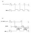
そして、スタートレバー13の操作部53を押し下げ操作すると、軸部54の球皿側端部54aが上昇してスタートレバーセンサ55がOFF状態(スタートレバー13が操作されていないことを検出している状態)からON状態(スタートレバー13が操作されていることを検出している状態)になり(図9(a)参照)、遊技制御装置65は、可変表示装置3を始動して可変表示ゲームを開始する。可変表示ゲームが開始され、遊技者が操作部53を離すと、スタートレバー13が元の位置に戻ってスタートレバーセンサ55がOFF状態に戻る。すると、遊技制御装置65は、振動モータ62を所定時間(例えば、約3秒)駆動し、振動手段60により球皿10を振動させる。このように、スタートレバー13の操作に基づいて球皿10を振動させることができるので、球皿10内で遊技球が詰まる不具合を解消することができ、一度に大量の遊技球をスムーズに取り込めるようにすることができる。また、スタートレバー13を操作して今回の可変表示ゲームを行うとともに、次回の可変表示ゲームの賭けに取り込む遊技球を詰まることなく流下するように準備することができる。したがって、可変表示ゲームを連続して迅速に行うことができ、遊技の興趣を維持し易い。   When the operation portion 53 of the start lever 13 is pushed down, the ball tray side end portion 54a of the shaft portion 54 rises and the start lever sensor 55 is in an OFF state (it is detected that the start lever 13 is not operated). State) changes to the ON state (the state in which it is detected that the start lever 13 is operated) (see FIG. 9A), and the game control device 65 starts the variable display device 3 to start the variable display game. To start. When the variable display game is started and the player releases the operation unit 53, the start lever 13 returns to the original position and the start lever sensor 55 returns to the OFF state. Then, the game control device 65 drives the vibration motor 62 for a predetermined time (for example, about 3 seconds), and vibrates the ball tray 10 by the vibration means 60. As described above, since the ball tray 10 can be vibrated based on the operation of the start lever 13, it is possible to eliminate the problem that the game balls are clogged in the ball tray 10, and a large number of game balls can be taken in at once. Can be. In addition, the present variable display game is played by operating the start lever 13, and it is possible to prepare to flow down without clogging the game balls to be taken in the bet of the next variable display game. Therefore, the variable display game can be performed quickly and continuously, and it is easy to maintain the interest of the game.

しかも、振動手段60は、球貯留部40と球整列部41との境界周辺に取り付けられているので、球皿10における遊技球の流路幅が狭くなる箇所、すなわち遊技球が詰まり易い箇所の周辺に直接振動を与えることができ、球皿10での球詰まりを効率よく解消することができる。また、振動モータ62により偏心部材61を回転させるので、連続して振動を発生させ、この振動により遊技球が球皿10で詰まることを防ぐことができる。また、固くて崩れ難い球詰まりが生じた場合であっても連続振動を加えることで解消し易くなり、球詰まりによって遊技が中断してしまう不都合を生じ難くすることができる。さらに、簡単な構成で振動手段60を実現することができる。このことから、球詰まりを生じ難い球スロ式遊技機1の製造効率を向上させることができる。   In addition, since the vibration means 60 is attached around the boundary between the ball storage unit 40 and the ball alignment unit 41, the game ball in the ball tray 10 is narrowed, that is, the game ball is easily clogged. Vibration can be directly applied to the periphery, and the clogging of the ball tray 10 can be efficiently eliminated. In addition, since the eccentric member 61 is rotated by the vibration motor 62, it is possible to continuously generate vibration and prevent the game ball from being clogged with the ball tray 10 by this vibration. Further, even when a ball clog that is hard and does not collapse easily occurs, it can be easily resolved by applying continuous vibration, and the inconvenience that the game is interrupted due to the ball clogging can be made difficult to occur. Furthermore, the vibration means 60 can be realized with a simple configuration. From this, it is possible to improve the manufacturing efficiency of the ball slot type gaming machine 1 in which ball clogging hardly occurs.

そして、可変表示ゲーム中にストップボタン14を操作すると、対応した可変表示が停止し、停止した識別情報の組み合せにより有効ライン上に賞態様が形成されると、球排出ユニット(図示せず)が作動して賞球が球排出口7から球皿10へ排出され、あるいはクレジットに遊技価値が付与される。   Then, when the stop button 14 is operated during the variable display game, the corresponding variable display is stopped, and when a prize mode is formed on the active line by the combination of the stopped identification information, a ball discharge unit (not shown) is inserted. In operation, the winning ball is discharged from the ball discharge port 7 to the ball tray 10, or a game value is given to the credit.

なお、振動手段60による振動の発生タイミングは、MAX取込ボタン12′の操作に基づくものであってもよい。具体的に説明すると、図9(b)に示すタイミングチャートにおいて、遊技制御装置65は、遊技者がMAX取込ボタン12′を押し(MAX取込ボタンセンサがON状態)、その後、押し動作を解除(MAX取込ボタンセンサがOFF状態)してから遅延時間を計測する。そして、所定の遅延時間(例えば、1秒)が経過したならば、振動モータ62を駆動(ON状態)して球皿10に所定時間(例えば、停止操作(ストップボタン14の操作)が終了するまで、あるいは3.1秒)に亘って振動を発生させる。このように、MAX取込ボタン12′を操作してから所定時間遅延させて球皿10を振動させると、大量の遊技球が取り込まれた後で球皿10内に残った遊技球が流動している間に遊技球同士のバランスが安定することを阻止して、球詰まりの発生を抑えることができる。   The generation timing of vibration by the vibration means 60 may be based on the operation of the MAX take-in button 12 ′. More specifically, in the timing chart shown in FIG. 9B, the game control device 65 causes the player to push the MAX take-in button 12 ′ (the MAX take-in button sensor is in the ON state), and then perform the pushing operation. The delay time is measured after the release (MAX take-in button sensor is OFF). Then, when a predetermined delay time (for example, 1 second) has elapsed, the vibration motor 62 is driven (ON state), and the predetermined time (for example, a stop operation (operation of the stop button 14) is completed in the ball tray 10). Vibration is generated for up to 3.1 seconds). In this way, when the ball tray 10 is vibrated with a predetermined time delay after the MAX loading button 12 'is operated, the game balls remaining in the ball tray 10 flow after a large amount of game balls are captured. During this time, the balance between the game balls can be prevented from being stabilized, and the occurrence of clogging of the balls can be suppressed.

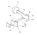
ところで、上記実施形態では、偏心部材61を回転して振動を発生させる振動手段60を球皿10の裏側に備えたが、本発明はこれに限定されず、振動手段を、直接球皿10を叩くノック機構で構成してもよい。例えば、図10に示す第2実施形態の振動手段80は、スタートレバー13の回動軸56の先端に接続されたリンク部81と、該リンク部81の端部に設けられたノック部82とから構成されている。リンク部81は、球取込口8が開設された方向へ延設されたロッド83と、該ロッド83のうち球貯留部40と球整列部41との境界の下方に対向する箇所に設けられたノック基部84とにより構成されている。また、ノック部82は、ノック基部84の後部上端から上方へ突出した状態で形成され、球皿10の底部裏面へ向けて移動して衝接可能となるように構成されている。このような構成の振動手段80を備えてスタートレバー13を押し下げ操作すると、リンク部81およびノック基部84が回動軸56周りに回動し、ノック部82が上昇して球皿10の底部に衝突し、球貯留部40と球整列部41との境界周辺に衝撃(振動)を与えることができる。したがって、簡単な構成で球皿10に衝撃力を与えて、球皿10を揺らすことができる。このことから、球皿10内で遊技球が詰まる不具合を短時間で効率よく解消することができる。   By the way, in the said embodiment, although the vibration means 60 which rotates the eccentric member 61 and generates a vibration was provided in the back side of the ball tray 10, this invention is not limited to this, A vibration means is directly attached to the ball tray 10. A knocking mechanism that strikes may be used. For example, the vibration means 80 of the second embodiment shown in FIG. 10 includes a link portion 81 connected to the tip of the rotation shaft 56 of the start lever 13, and a knock portion 82 provided at the end of the link portion 81. It is composed of The link portion 81 is provided at a position facing the lower side of the boundary between the ball storage portion 40 and the ball alignment portion 41 of the rod 83 extending in the direction in which the ball inlet 8 is established, and the rod 83. And a knock base 84. Further, the knock portion 82 is formed in a state of protruding upward from the rear upper end of the knock base portion 84, and is configured to move toward the bottom rear surface of the ball tray 10 so as to be able to hit. When the start lever 13 is pushed down with the vibration means 80 having such a configuration, the link portion 81 and the knock base portion 84 rotate around the rotation shaft 56, and the knock portion 82 rises to the bottom portion of the ball tray 10. Colliding and impact (vibration) can be applied to the periphery of the boundary between the sphere storage unit 40 and the sphere alignment unit 41. Therefore, the ball tray 10 can be shaken by applying an impact force to the ball tray 10 with a simple configuration. From this, the trouble that the game ball is clogged in the ball tray 10 can be solved efficiently in a short time.

なお、ノック部82の先端または球皿10のうちノック部82の先端に対向する箇所のいずれか一方、あるいは両方にゴム板材等の緩衝部材85を設ければ、ノック部82からの衝撃力により球皿10が損傷してしまう不具合や、ノック部82自体が破損してしまう不具合を抑制することができて好適である。   If a shock absorbing member 85 such as a rubber plate is provided at either or both of the tip of the knock portion 82 or the portion of the ball tray 10 that faces the tip of the knock portion 82, the impact force from the knock portion 82 It is possible to suppress a problem that the ball tray 10 is damaged and a problem that the knock part 82 itself is damaged, which is preferable.

ところで、上記実施形態では、振動手段60,80により球皿10のうち球貯留部40と球整列部41との境界周辺にのみ振動を与えるようにしたが、本発明はこれに限定されず、球皿10のほかの部分にも振動を与えるようにしてもよい。例えば、図11および図12に示すように、上記各実施形態のスタートレバー13の軸部54の先端、すなわち球皿側端部54aに球皿10の底部裏面へ衝接可能な球貯留ノック部87を、球貯留部40の底部裏面の略中央へ向けて突出し、スタートレバー13の押し下げ操作に伴って、球皿10に球貯留ノック部87を衝突させることにより球貯留部40の中央部周辺にも衝撃(振動)を与えるようにしてもよい。このような球貯留ノック部87を設けると、簡単な構造で球貯留部40に衝撃力を与えることができる。したがって、偏心部材61の回転により、あるいはノック部82の衝突により球貯留部40と球整列部41との境界周辺を振動させ、加えて、球貯留ノック部87により球貯留部40も振動させることができ、球皿10での球詰まりを一層効率よく解消することができる。   By the way, in the said embodiment, it was made to give a vibration only to the periphery periphery of the ball storage part 40 and the ball | bowl alignment part 41 among the ball dishes 10 by the vibration means 60 and 80, but this invention is not limited to this, You may make it give a vibration also to the other part of the ball tray 10. FIG. For example, as shown in FIGS. 11 and 12, a ball storage knock portion that can come into contact with the tip of the shaft portion 54 of the start lever 13 of each of the above embodiments, that is, the ball tray side end portion 54 a to the bottom rear surface of the ball tray 10 87 protrudes toward the substantially center of the bottom rear surface of the ball reservoir 40, and the ball reservoir knocking portion 87 collides with the ball tray 10 as the start lever 13 is pushed down. Also, an impact (vibration) may be applied. When such a ball storage knock portion 87 is provided, an impact force can be applied to the ball storage portion 40 with a simple structure. Therefore, the periphery of the boundary between the sphere reservoir 40 and the sphere alignment portion 41 is vibrated by the rotation of the eccentric member 61 or by the collision of the knock portion 82, and the sphere reservoir 40 is also vibrated by the sphere reservoir knock 87. And clogging of the balls in the ball tray 10 can be solved more efficiently.

また、球貯留ノック部87の先端または球貯留部40のうち球貯留ノック部87の先端に対向する箇所のいずれか一方、あるいは両方にゴム板材等の緩衝部材88を設ければ、球貯留ノック部87からの衝撃力により球皿10が損傷してしまう不具合や、球貯留ノック部87自体が破損してしまう不具合を抑制することができて好適である。   Further, if a buffer member 88 such as a rubber plate material is provided at one or both of the tip of the sphere storage knock portion 87 or the portion of the sphere storage portion 40 that faces the tip of the sphere storage knock portion 87, the ball storage knock It is possible to suppress a problem that the ball tray 10 is damaged by the impact force from the part 87 and a problem that the ball storage knock part 87 itself is damaged.

上記実施形態では、球皿10のうち少なくとも球貯留部40と球整列部41との境界周辺に振動を与えるようにしたが、球貯留部40にのみ振動を与えるようにしてもよい。すなわち、球スロ式遊技機1は、球貯留部40と球整列部41との境界周辺を振動させる振動手段60,80を設けず、スタートレバー13の軸部54の先端に球貯留ノック部87を突出し、スタートレバー13を叩く(押し下げる)と、回動軸56を中心に球貯留ノック部87が上へ回動して球貯留部40の中心部周辺のみを叩くように構成してもよく、このように構成しても、球皿10での球詰まりを解消し易い。   In the above embodiment, vibration is applied to at least the periphery of the boundary between the sphere storage unit 40 and the sphere alignment unit 41 in the ball tray 10, but vibration may be applied only to the sphere storage unit 40. That is, the ball slot machine 1 does not include the vibration means 60 and 80 that vibrate around the boundary between the ball storage unit 40 and the ball alignment unit 41, and the ball storage knock unit 87 at the tip of the shaft portion 54 of the start lever 13. When the start lever 13 is struck and pushed (pressed down), the sphere storage knock 87 may rotate upward about the rotation shaft 56 and hit only around the center of the sphere storage 40. Even if constituted in this way, it is easy to eliminate ball clogging in the ball tray 10.

なお、上記した振動手段60,80および球貯留ノック部87は、球皿10の下方に限らず、球皿10の前方や側方に設けてもよい。すなわち、球皿10の周辺、具体的には球皿10に振動を伝達して球詰まりの解消を達成できる範囲内であれば、どの位置に設けてもよい。   The vibrating means 60 and 80 and the ball storage knock portion 87 described above may be provided not only below the ball tray 10 but also at the front or side of the ball tray 10. That is, it may be provided at any position as long as it is within a range in which the vibration can be transmitted to the periphery of the ball tray 10, specifically, the ball tray 10 can be eliminated.

上記した実施形態は、球スロ式遊技機1を例にして説明したが、本発明はこれに限らず、遊技における入力操作をするための入力操作部を備え、遊技実行に際して球皿から複数の遊技球を取り込む遊技機であれば、どのようなものでもよい。   Although the above-described embodiment has been described by taking the ball slot type gaming machine 1 as an example, the present invention is not limited to this, and includes an input operation unit for performing an input operation in a game, and a plurality of pieces from the ball tray are executed when the game is executed. Any game machine that takes in a game ball may be used.

前記した実施の形態は全ての点で例示であって制限的なものではないと考えられるべきである。本発明は、上記した説明に限らず特許請求の範囲によって示され、特許請求の範囲と均等の意味及び範囲内での全ての変更が含まれるものである。   The above-described embodiments are examples in all respects and should be considered not restrictive. The present invention is not limited to the above description, but is defined by the scope of the claims, and includes all modifications within the scope and meaning equivalent to the scope of the claims.

球スロ式遊技機の正面図である。It is a front view of a ball slot machine. 前面枠を開放した球スロ式遊技機の状態図である。It is a state figure of the ball slot type game machine which opened the front frame. 球皿ユニットの上面図である。It is a top view of a ball tray unit. 球皿ユニットの後方から見た斜視図である。It is the perspective view seen from the back of a ball tray unit. 球取込装置の概略図であり、(a)は遊技球を取り込まない状態図、(b)遊技球を取り込む状態図である。It is the schematic of a ball taking-in apparatus, (a) is a state figure which does not take in a game ball, (b) It is a state figure which takes in a game ball. 図3における球皿ユニットのA−A断面図であり、(a)はスタートレバーが押し下げ操作されていないときの説明図、(b)はスタートレバーが押し下げ操作されたときの説明図である。FIG. 4 is a cross-sectional view of the ball tray unit taken along line AA in FIG. 3, where (a) is an explanatory view when the start lever is not pushed down, and (b) is an explanatory view when the start lever is pushed down. 偏心部材と振動モータとから構成される振動手段の概略図である。It is the schematic of the vibration means comprised from an eccentric member and a vibration motor. 球スロ式遊技機に備えられる制御装置のブロック構成図である。It is a block block diagram of the control apparatus with which a ball slot machine is equipped. (a)はスタートレバーの操作に基づいて振動モータを駆動する場合のタイミングチャート、(b)はベットボタンの操作に基づいて振動モータを駆動する場合のタイミングチャートである。(A) is a timing chart in the case of driving the vibration motor based on the operation of the start lever, and (b) is a timing chart in the case of driving the vibration motor based on the operation of the bet button. ノック部を備えた第2実施形態の振動手段の概略図である。It is the schematic of the vibration means of 2nd Embodiment provided with the knock part. 球貯留ノック部を備えたスタートレバーの断面図であり、(a)はスタートレバーが押し下げ操作されていないときの説明図、(b)はスタートレバーが押し下げ操作されたときの説明図である。It is sectional drawing of the start lever provided with the ball | bowl storage knock part, (a) is explanatory drawing when the start lever is not pushed down operation, (b) is explanatory drawing when the start lever is pushed down operation. ノック部を有する振動手段と球貯留ノック部とを設けたスタートレバーの概略図である。It is the schematic of the start lever which provided the vibration means which has a knock part, and a ball storage knock part.

符号の説明Explanation of symbols

1 球スロ式遊技機
3 可変表示装置
4 前面枠
5 開口窓部
7 球排出口
8 球取込口
9 球皿ユニット
10 球皿
13 スタートレバー
34 球皿カバー部材
35 球皿本体
40 球貯留部
41 球整列部
53 操作部
54 軸部
54a 球皿側端部
55 スタートレバーセンサ
56 回動軸
60 振動手段
61 偏心部材
62 振動モータ
63 保持部材
80 振動手段
81 リンク部
82 ノック部
83 ロッド
84 ノック基部
85 緩衝部材
87 球貯留ノック部
88 緩衝部材
DESCRIPTION OF SYMBOLS 1 Ball slot type game machine 3 Variable display device 4 Front frame 5 Opening window part 7 Ball discharge port 8 Ball take-in port 9 Ball tray unit 10 Ball tray 13 Start lever 34 Ball tray cover member 35 Ball tray main body 40 Ball storage section 41 Ball alignment portion 53 Operation portion 54 Shaft portion 54a Ball tray side end portion 55 Start lever sensor 56 Rotating shaft 60 Vibrating means 61 Eccentric member 62 Vibrating motor 63 Holding member 80 Vibrating means 81 Link portion 82 Knock portion 83 Rod 84 Knock base portion 85 Buffer member 87 Ball storage knock 88 Buffer member

Claims (4)

前面枠に配設される球皿に遊技球を貯留し、遊技者によって選択された賭け数に応じて前記球皿から所定数の遊技球を一単位として球取込口を介して取り込み、スタートレバーの操作に基づいて可変表示ゲームを行い、前記賭け数に応じた有効ライン上に賞態様が形成されると遊技球を賞球として排出する遊技機において、
前記球皿は、遊技球を貯留する球貯留部と、該球貯留部から球取込口へ流下する遊技球を整列させる球整列部と、を備え、
前記スタートレバーは、
前記球皿の球貯留部の前方に突出した状態で配置され、遊技者が操作可能な操作部と、
該操作部から球貯留部の下方へ向けて延設された軸部と、
該軸部の中間を軸支して操作部を上下動可能とする回動軸と、
を備え、
前記球皿の周辺には、当該球皿を振動させる振動手段を設け
該振動手段は、前記スタートレバーの回動軸に接続されたリンク部と、該リンク部の端部に上方へ突出した状態で設けられ、球皿の底部裏面へ衝接可能なノック部と、を備え、
前記スタートレバーの操作に基づいて、リンク部が回動軸周りに回動し、ノック部が上昇して球皿の底部裏面に衝突して球皿を振動させるように構成されたことを特徴とする遊技機。
Game balls are stored in a ball tray arranged on the front frame, and a predetermined number of game balls are taken as a unit from the ball tray according to the number of bets selected by the player, and started. In a gaming machine that performs a variable display game based on an operation of a lever and discharges a game ball as a prize ball when a prize mode is formed on an active line corresponding to the number of bets,
The ball tray includes a ball storage unit that stores game balls, and a ball alignment unit that aligns the game balls flowing down from the ball storage unit to the ball intake port,
The start lever is
An operation unit that is arranged in a protruding state in front of the ball storage unit of the ball tray and that can be operated by the player,
A shaft portion extending from the operation portion toward the lower side of the ball storage portion;
A rotating shaft that pivotally supports the middle of the shaft portion and allows the operation portion to move up and down;
With
The periphery of the sphere dish provided vibrating means for vibrating the ball pan,
The vibration means includes a link portion connected to the rotation shaft of the start lever, a knock portion provided in a state of protruding upward at an end portion of the link portion, and capable of striking the bottom rear surface of the ball tray, With
Based on the operation of the start lever , the link portion rotates around the rotation axis, the knock portion rises and collides with the bottom rear surface of the ball tray to vibrate the ball tray. To play.
前記ノック部の先端および/または前記球皿のうちノック部の先端に対向する箇所に緩衝部材を設けたことを特徴とする請求項1に記載の遊技機。The gaming machine according to claim 1, wherein a buffer member is provided at a position of the tip of the knock portion and / or the tip of the knock plate facing the tip of the knock portion. 前記スタートレバーの軸部の先端には、球貯留部の底部裏面へ衝接可能な球貯留ノック部を備え、At the tip of the shaft portion of the start lever is provided with a ball storage knock portion that can come into contact with the bottom rear surface of the ball storage portion,
前記スタートレバーの操作に基づいて、球貯留ノック部が球貯留部の底部裏面に衝突して球貯留部を振動させるように構成されたことを特徴とする請求項1に記載の遊技機。  2. The gaming machine according to claim 1, wherein the ball storage knock portion collides with a bottom rear surface of the ball storage portion to vibrate the ball storage portion based on an operation of the start lever.
前記球貯留ノック部の先端および/または前記球皿のうち球貯留ノック部の先端に対向する箇所に緩衝部材を設けたことを特徴とする請求項3に記載の遊技機。 The gaming machine according to claim 3, characterized in that a cushioning member at a location opposite the tip of the ball reservoir knock part of the tip and / or the ball dish the ball reservoir knock part.
JP2004208751A 2004-07-15 2004-07-15 Game machine Expired - Fee Related JP4416588B2 (en)

Priority Applications (1)

Application Number Priority Date Filing Date Title
JP2004208751A JP4416588B2 (en) 2004-07-15 2004-07-15 Game machine

Applications Claiming Priority (1)

Application Number Priority Date Filing Date Title
JP2004208751A JP4416588B2 (en) 2004-07-15 2004-07-15 Game machine

Publications (3)

Publication Number Publication Date
JP2006026075A JP2006026075A (en) 2006-02-02
JP2006026075A5 JP2006026075A5 (en) 2007-06-21
JP4416588B2 true JP4416588B2 (en) 2010-02-17

Family

ID=35893092

Family Applications (1)

Application Number Title Priority Date Filing Date
JP2004208751A Expired - Fee Related JP4416588B2 (en) 2004-07-15 2004-07-15 Game machine

Country Status (1)

Country Link
JP (1) JP4416588B2 (en)

Families Citing this family (4)

* Cited by examiner, † Cited by third party
Publication number Priority date Publication date Assignee Title
JP4913464B2 (en) * 2006-03-31 2012-04-11 株式会社北電子 Game machine
CA2599353C (en) * 2006-09-06 2011-05-24 Lg Electronics Inc. Dryer with clogging detecting function
CA2599375C (en) 2006-09-06 2011-06-21 Lg Electronics Inc. Clogging detecting system for dryer
JP5136445B2 (en) * 2009-01-29 2013-02-06 奥村遊機株式会社 Pachinko machine

Also Published As

Publication number Publication date
JP2006026075A (en) 2006-02-02

Similar Documents

Publication Publication Date Title
JP2006247170A (en) Game machine
JP4553370B2 (en) Pachinko machine
JP4416588B2 (en) Game machine
JPWO2007046191A1 (en) Game machine
JP2001070519A (en) Pachinko machine
JP4895904B2 (en) Game machine
JP4247322B2 (en) Bullet ball machine
JP4885509B2 (en) Game machine
JP4499124B2 (en) Bullet ball machine
JP5129361B2 (en) Pachinko machine
JP5043325B2 (en) Game machine
JP2016154709A (en) Game machine
JP2001070526A (en) Pachinko game machine
JP2010214162A (en) Pinball game machine
JP2006026075A5 (en)
JP4304680B2 (en) Pachinko machine winning device
JPH10249017A (en) Upper ball tray for pachinko machine
JP4919436B2 (en) Ball passing unit and game machine
JP4756199B2 (en) Bullet ball machine
JP2005261796A (en) Game machine
JP4885510B2 (en) Game machine
JP4567014B2 (en) Bullet ball machine
JP2001231999A (en) Game machine
JP2602692B2 (en) Pachinko machine
JP2003310935A (en) Pachinko game machine

Legal Events

Date Code Title Description
A521 Written amendment

Free format text: JAPANESE INTERMEDIATE CODE: A523

Effective date: 20070509

A621 Written request for application examination

Free format text: JAPANESE INTERMEDIATE CODE: A621

Effective date: 20070509

TRDD Decision of grant or rejection written
A01 Written decision to grant a patent or to grant a registration (utility model)

Free format text: JAPANESE INTERMEDIATE CODE: A01

Effective date: 20091124

A01 Written decision to grant a patent or to grant a registration (utility model)

Free format text: JAPANESE INTERMEDIATE CODE: A01

A61 First payment of annual fees (during grant procedure)

Free format text: JAPANESE INTERMEDIATE CODE: A61

Effective date: 20091124

R150 Certificate of patent or registration of utility model

Ref document number: 4416588

Country of ref document: JP

Free format text: JAPANESE INTERMEDIATE CODE: R150

Free format text: JAPANESE INTERMEDIATE CODE: R150

FPAY Renewal fee payment (event date is renewal date of database)

Free format text: PAYMENT UNTIL: 20121204

Year of fee payment: 3

FPAY Renewal fee payment (event date is renewal date of database)

Free format text: PAYMENT UNTIL: 20121204

Year of fee payment: 3

FPAY Renewal fee payment (event date is renewal date of database)

Free format text: PAYMENT UNTIL: 20121204

Year of fee payment: 3

FPAY Renewal fee payment (event date is renewal date of database)

Free format text: PAYMENT UNTIL: 20121204

Year of fee payment: 3

FPAY Renewal fee payment (event date is renewal date of database)

Free format text: PAYMENT UNTIL: 20131204

Year of fee payment: 4

R250 Receipt of annual fees

Free format text: JAPANESE INTERMEDIATE CODE: R250

R250 Receipt of annual fees

Free format text: JAPANESE INTERMEDIATE CODE: R250

R250 Receipt of annual fees

Free format text: JAPANESE INTERMEDIATE CODE: R250

R250 Receipt of annual fees

Free format text: JAPANESE INTERMEDIATE CODE: R250

R250 Receipt of annual fees

Free format text: JAPANESE INTERMEDIATE CODE: R250

R250 Receipt of annual fees

Free format text: JAPANESE INTERMEDIATE CODE: R250

LAPS Cancellation because of no payment of annual fees