JP4416463B2 - Development device - Google Patents
Development device Download PDFInfo
- Publication number
- JP4416463B2 JP4416463B2 JP2003330065A JP2003330065A JP4416463B2 JP 4416463 B2 JP4416463 B2 JP 4416463B2 JP 2003330065 A JP2003330065 A JP 2003330065A JP 2003330065 A JP2003330065 A JP 2003330065A JP 4416463 B2 JP4416463 B2 JP 4416463B2
- Authority
- JP
- Japan
- Prior art keywords
- developer
- toner
- developing
- screw
- image
- Prior art date
- Legal status (The legal status is an assumption and is not a legal conclusion. Google has not performed a legal analysis and makes no representation as to the accuracy of the status listed.)
- Expired - Fee Related
Links
Images


Landscapes
- Dry Development In Electrophotography (AREA)
Description
本発明は静電記録方式や電子写真方式を用いた複写機,レーザービームプリンタ,ファクシミリ、印刷装置などに用いられる現像装置に関するものである。 The present invention relates to a developing device used for a copying machine, a laser beam printer, a facsimile, a printing device, etc. using an electrostatic recording method or an electrophotographic method.
従来、像担持体上に形成された静電潜像を顕在化するに際して非磁性トナーと磁性キャリアから成る2成分現像剤を用いた2成分現像方法が広く用いられている。 2. Description of the Related Art Conventionally, a two-component developing method using a two-component developer composed of a non-magnetic toner and a magnetic carrier has been widely used for revealing an electrostatic latent image formed on an image carrier.
この2成分現像方法は、現像装置内の攪拌部材によって攪拌された現像剤を内部にマグネットを有する現像剤担持体に担持せしめ、この現像剤を用いて像担持体との対向部にて静電潜像を可視化するものである。 In this two-component development method, a developer stirred by a stirring member in a developing device is carried on a developer carrying member having a magnet inside, and the developer is used to electrostatically develop the portion facing the image carrying member. The latent image is visualized.
2成分現像装置は、別に設けられたトナー補給容器からトナーのみを補給して使用することからできることから、2成分現像剤のトナー濃度(即ち、キャリア粒子とトナー粒子の合計重量に対するトナー粒子重量の割合)は、画像品質を安定化させる上で極めて重要な要素になっている。現像剤のトナー粒子は現像時に消費されるためにトナー濃度は変化する。このため、現像剤濃度制御装置(ATR)を使用して適時現像剤のトナー濃度を正確に検出し、トナー濃度の変化に応じてトナー補給を行い、十分に撹拌を行いトナー濃度を常に一定に制御して画像の品位を保持する必要がある。 Since the two-component developing device can be used by replenishing only toner from a separately provided toner replenishing container, the toner concentration of the two-component developer (that is, the toner particle weight relative to the total weight of carrier particles and toner particles). The ratio is an extremely important factor in stabilizing the image quality. Since the toner particles of the developer are consumed during development, the toner concentration changes. For this reason, the developer concentration control device (ATR) is used to accurately detect the toner concentration of the developer in a timely manner, replenish the toner according to the change in the toner concentration, and sufficiently agitate to keep the toner concentration constant. It is necessary to control and maintain the quality of the image.
このように現像による現像装置内のトナー濃度の変化を補正するため(即ち、現像装置に補給するトナー量を制御するため)、現像容器中のトナー濃度検知装置及び濃度制御装置としては従来から種々の方式のものが実用化されている。 In order to correct a change in toner density in the developing device due to development in this way (that is, to control the amount of toner supplied to the developing device), various toner density detecting devices and density control devices in the developing container have been conventionally used. The method of this type is put into practical use.
例えば、現像スリーブ或は現像容器の現像剤搬送経路に近接し、現像スリーブ上に搬送された現像剤或は現像容器内の現像剤に光を当てたときの反射率がトナー濃度により異なることを利用してトナー濃度を検知し制御する現像剤濃度制御装置、或は現像剤の側壁に磁性キャリアと非磁性トナーの混合比率による見掛けの透磁率を検知してこれを電気信号に変換するインダクタンスヘッドからの検出信号によって現像器内のトナーの濃度を検知し、基準値との比較によってトナーを補給するようにしたインダクタンス検知方式の現像剤濃度制御装置が使用されている。 For example, the reflectivity when light is applied to the developer conveyed on the developing sleeve or the developer in the developing container close to the developer conveying path of the developing sleeve or the developing container varies depending on the toner concentration. Developer density control device that detects and controls the toner density by using, or an inductance head that detects the apparent magnetic permeability due to the mixing ratio of magnetic carrier and non-magnetic toner on the side wall of the developer and converts it into an electrical signal Inductance detection type developer concentration control devices are used in which the density of toner in the developing device is detected by a detection signal from the toner and the toner is replenished by comparison with a reference value.
又、像担持体としての感光ドラム上に形成したパッチ画像濃度をその表面に対向した位置に設けた光源及びその反射光を受けるセンサーにより読み取り、読み取った画像濃度をアナログ−デジタル変換器でデジタル信号に変換した後CPUに送り、CPUで初期設定値より濃度が高い場合、初期設定値に戻るまでトナー補給が停止され、初期設定値より濃度が低ければ初期設定値に戻るまで強制的にトナーが補給され、その結果、トナー濃度が間接的に所望の値に維持される方式等がある。 The patch image density formed on the photosensitive drum as an image carrier is read by a light source provided at a position facing the surface and a sensor that receives the reflected light, and the read image density is converted into a digital signal by an analog-digital converter. If the density is higher than the initial setting value, the toner supply is stopped until the initial setting value is returned. If the density is lower than the initial setting value, the toner is forcibly used until the initial setting value is returned. For example, there is a method in which the toner density is indirectly maintained at a desired value.
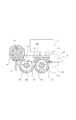
ここで、一般的な2成分現像器について図3に基づき説明する。 Here, a general two-component developing device will be described with reference to FIG.
図3において、50は現像剤担持体たる現像スリーブ、現像スリーブ50内には固定配置された磁界発生手段たるマグネットローラー、53,54は撹拌搬送手段たる搬送スクリュー、51は現像剤を現像スリーブ50表面に薄層形成するために配置された現像剤層厚規制部材たる規制ブレードである。現像スリーブ50には、電源(図示せず)から直流バイアス及び交流バイアスが印加されるようになっている。一般に、交流バイアスを印加すると現像効率が増し、画像は高品位になる。
In FIG. 3, 50 is a developing sleeve as a developer carrying member, a magnet roller as magnetic field generating means fixedly arranged in the developing
ここで、感光ドラム上に形成された静電潜像を、図3の現像装置を用いて2成分磁気ブラシ法により顕像化する現像工程と現像剤の循環系とについて説明する。 Here, a developing process for visualizing the electrostatic latent image formed on the photosensitive drum by the two-component magnetic brush method using the developing device of FIG. 3 and a developer circulation system will be described.
先ず、現像スリーブ50の回転に伴い磁極N1によって現像スリーブ50上に汲み上げられた現像剤は、磁極N1から磁極S2へと搬送される過程において、現像スリーブ50に担持される量を規制ブレード51によって規制され、現像スリーブ50上に薄層形成される。ここで、薄層形成された現像剤が、現像主極である磁極S1に搬送されてくると磁気力によって穂立ちが形成される。この穂状に形成された現像剤によって上記静電潜像が現像され、その後、磁極N3及び磁極N1による反発磁界によって現像スリーブ50上の現像剤は、現像剤容器内に戻される。
First, the amount of developer carried on the developing
このように、2成分現像法による現像装置においては、互いに同極性の磁極を並べて配置することにより、現像後の現像剤を一旦現像スリーブから剥ぎとり、前の画像履歴を残さない構成としている。 As described above, in the developing device using the two-component developing method, the magnetic poles having the same polarity are arranged side by side so that the developer after development is once peeled off from the developing sleeve and the previous image history is not left.
現像剤にキャリアとトナーを有する二成分現像剤を用いる現像装置においては、トナーとキャリアが良好に攪拌されて搬送されるのが望ましい。そこで、図4に示すような像担持体へのトナーの供給側に位置する第1の空間部と、補給トナーの供給を受ける第2の空間部側とに仕切り壁でケース内を分割し、それぞれの空間部にスクリュー状の攪拌部材を互いに平行に配置した2軸攪拌方式の現像装置が提案されている。ここで、41は現像スリーブ、46はトナー濃度センサー、5は補給用トナー容器である。2軸攪拌方式の現像装置では、第1の空間部に配置された第1の攪拌部材(44a)と、第2の空間部側に配置された第2の攪拌部材(45a)とでそれぞれ現像剤を攪拌搬送し、搬送された現像剤を各攪拌部材の端部側に形成された受け渡し部から各空間部内に送り込んで循環させている。これを上から見たものが図5である。ここで41は現像スリーブ、43,44は搬送スクリューであり、矢印のように現像剤を循環し、撹拌性、搬送性を維持している。このような2軸タイプの搬送スクリューについては、特許文献1、2にて説明図として開示されており2つの軸を横渡しする部分のスクリュー部には板上のフィンがついているものが、紹介されている。
しかしながら、最近の白黒/カラープリンター、白黒/カラーコピーの小型化に対して現像装置そのものの小型化が要求されており、小さい現像装置で基本機能を維持することの課題がある。 However, in recent black-and-white / color printers and black-and-white / color copying, downsizing of the developing device itself is required, and there is a problem of maintaining the basic functions with a small developing device.
小型化に関しては現像装置自体を小さくしていった場合の課題として、長手方向についてはトナー補給口を現像スリーブ長より外側に従来配置できていたのが、長手方向で現像スリーブ長内に配置する必要がある。つまり、先の図5に示すように現像剤が搬送される場合、ここでポイント47より左側(搬送方向上流)通常、トナー補給口があり、現像スリーブに補給されたトナーが到達するのに十分の距離がとれていた。それに対して小型化すると、図6で示されるように丸印からトナーをするために問題として補給されたトナーが十分攪拌されないで、現像スリーブから離れている搬送スクリュー(以下Bスクリューと称す)から現像スリーブに近接する搬送スクリュー(以下、Aスクリューと称す)へ移動する前に十分攪拌できる距離がとれないため、補給されたトナーの帯電性が悪く、トナー飛散や画像かぶりを生じていた。 Regarding downsizing, as a problem when the developing device itself is made small, the toner replenishing port has conventionally been arranged outside the length of the developing sleeve in the longitudinal direction, but is arranged in the developing sleeve length in the longitudinal direction. There is a need. That is, when the developer is transported as shown in FIG. 5, there is usually a toner replenishing port on the left side of the point 47 (upstream in the transport direction), which is sufficient for the toner replenished to the developing sleeve to reach. The distance was taken. On the other hand, when the size is reduced, as shown in FIG. 6, the toner replenished as a problem in order to remove the toner from the circle is not sufficiently agitated, and from the conveying screw (hereinafter referred to as B screw) which is away from the developing sleeve. Since a sufficient stirring distance cannot be taken before moving to a conveying screw (hereinafter referred to as “A screw”) close to the developing sleeve, the replenished toner has poor chargeability, causing toner scattering and image fogging.
更に大きな課題として、現像剤担持体(現像スリーブ)に現像剤を供給搬送するAスクリューの搬送においても長手方向で画像領域内で返しスクリュー部(逆スクリュー部)を形成し、そして、順スクリュー部の螺旋翼部と逆スクリュー部の螺旋翼部とを離して設けた場合、現像剤の残面が不安定になることで、現像剤担持体への現像剤供給が不十分となり、現像剤のコート不良が生じ、結果として、端部にて画像白抜け等の問題が生じてしまった。 As a further major problem, a return screw portion (reverse screw portion) is formed in the image region in the longitudinal direction in the conveyance of the A screw for supplying and conveying the developer to the developer carrying member (developing sleeve), and the forward screw portion. When the spiral blade portion of the screw and the spiral blade portion of the reverse screw portion are provided apart, the remaining surface of the developer becomes unstable, so that the developer supply to the developer carrier becomes insufficient, and the developer As a result, a coating defect occurred, and problems such as image blanking occurred at the edge.
また、現像装置の小型化に伴い、搬送スクリュー自体も小さくなることで、これらの現象は更に顕著になっていた。 In addition, as the developing device is downsized, the transport screw itself is also reduced, and these phenomena become more remarkable.
本発明の目的は、現像装置の小型化を図った際に、現像剤担持体への現像剤の供給不良に起因した現像剤のコート不良や画像白抜けを防止することである。さらに、トナーの撹拌不良を防ぎ、トナーの帯電性を維持することで飛散、かぶりを防止し、画像むらのない高画質画像を提供することである。 SUMMARY OF THE INVENTION An object of the present invention is to prevent developer coating failure and image blanking due to poor supply of developer to the developer carrying member when the developing device is downsized. Further, it is to prevent a toner from being agitated and maintain toner chargeability to prevent scattering and fogging and to provide a high-quality image without image unevenness.
本発明は、トナーとキャリアを混合した現像剤を収容する現像容器と、
前記現像容器内の現像剤を収納する現像室と、
前記現像室と循環経路を形成し、前記現像容器内の現像剤を攪拌する攪拌室と、
前記現像室と前記攪拌室を仕切る仕切り部と、
前記現像室内の現像剤を担持して像担持体と対向する現像領域へ現像剤を搬送する現像剤担持体と、
前記現像剤担持体と対向して設けられ、前記現像剤担持体へ現像剤を供給するとともに、前記現像室内の現像剤を前記攪拌室に向けて搬送する搬送部材と、を有する現像装置であって、
前記搬送部材は、回転可能な回転軸と、前記回転軸上に螺旋状に形成され、現像剤を循環方向へ搬送する第1の搬送翼部と、前記回転軸上に螺旋状に形成され、現像剤を循環方向とは逆方向へ搬送する第2の搬送翼部と、を有する現像装置において、
現像剤の循環方向に関して前記現像室から前記攪拌室へ連絡する連絡路は、前記現像領域と重なる領域を有し、前記第1の搬送翼部と前記第2の搬送翼部は、前記連絡路と対向する位置において、互いの螺旋状の搬送翼部同士が直接結合されており、前記第1の搬送翼部と前記第2の搬送翼部が結合することで形成された空間の少なくとも一部を底上げした領域が設けられていることを特徴とする。
The present invention includes a developer container containing a developer in which toner and a carrier are mixed,
A developing chamber for storing the developer in the developing container;
A stirring chamber for forming a circulation path with the developing chamber and stirring the developer in the developing container;
A partition for partitioning the developing chamber and the stirring chamber;
A developer carrying member that carries the developer in the developing chamber and conveys the developer to a developing region facing the image carrying member;
A developing device that is provided facing the developer carrying member, and that supplies a developer to the developer carrying member and conveys the developer in the developing chamber toward the stirring chamber. And
The conveyance member is formed in a spiral shape on the rotation shaft, a first conveyance blade portion that is spirally formed on the rotation shaft , conveys the developer in a circulation direction, and a spiral shape on the rotation shaft, In a developing device having a second conveying blade for conveying the developer in a direction opposite to the circulation direction,
The communication path that communicates from the developing chamber to the stirring chamber with respect to the developer circulation direction has an area that overlaps the developing area, and the first conveying blade section and the second conveying blade section are connected to the communication path. And at least a part of the space formed by coupling the first and second conveying blades to each other at positions facing each other. A region where the bottom is raised is provided.
本発明によれば、現像装置の小型化を図った際にも、現像剤担持体への現像剤供給を確実に行い、現像剤のコート不良や画像白抜けを防止することができる。さらに、現像剤の撹拌不良を防ぎ、トナーの帯電性を維持することで飛散、かぶりを防止し、画像むらのない高画質画像を提供することができる。 According to the present invention, even when the developing device is downsized, it is possible to reliably supply the developer to the developer carrying member and to prevent poor coating of the developer and white spots in the image. Further, it is possible to prevent poor stirring of the developer and maintain the chargeability of the toner, thereby preventing scattering and fogging and providing a high-quality image without image unevenness.
本発明の第1の実施形態について説明する。 A first embodiment of the present invention will be described.
図9は、本実施形態に係る画像形成装置の一例たる電子写真方式のカラープリンタ(以下、プリンタという)の概略構成を示す模式的断面図である。 FIG. 9 is a schematic cross-sectional view showing a schematic configuration of an electrophotographic color printer (hereinafter referred to as a printer) as an example of the image forming apparatus according to the present embodiment.
かかるプリンタにあっては、図9に示すように、矢印方向に回転する潜像担持体たる電子写真感光ドラム3(以下、感光ドラム3という)を備え、感光ドラム3の周囲には、帯電器ローラ4、現像ロータリー2、4個の現像装置1、1次転写ローラ9、クリーニング手段6、中間転写ベルト8、2次転写ローラ10及び感光ドラム3の上方に配設されたレーザービームスキャナからなる画像形成手段が配設される。
As shown in FIG. 9, the printer includes an electrophotographic photosensitive drum 3 (hereinafter referred to as a photosensitive drum 3) that is a latent image carrier that rotates in the direction of the arrow. A roller 4, a developing
現像装置1は、現像器1M,1C,1Y,1Kを備え、各現像器1M,1C,1Y,1Kは、トナー粒子とキャリア粒子とを含有する現像剤(二成分現像剤)を感光ドラム3表面に供給するようになっている。尚、現像器1M、現像器1C、現像器1Y、現像器1Kは、それぞれマゼンタトナー、シアントナー、イエロートナー、ブラックトナーを含有する現像剤を使用するようになっている。
The developing device 1 includes developing
被複写原稿は、原稿読み取り装置(図示せず)で読み取られるようになっている。この読み取り装置はCCD等の、原稿画像を電気信号に変換する光電変換素子を有しており原稿のイエロー画像情報、マゼンタ画像情報、シアン画像情報、白黒画像情報に、それぞれ対応した画像信号を出力するようになっている。スキャナLSに内蔵された半導体レーザーは、これらの画像信号に対応して制御され、レーザービームLを照射する。 The document to be copied is read by a document reading device (not shown). This reading device has a photoelectric conversion element that converts an original image into an electrical signal, such as a CCD, and outputs image signals corresponding respectively to yellow image information, magenta image information, cyan image information, and black and white image information of the original. It is supposed to be. The semiconductor laser incorporated in the scanner LS is controlled in accordance with these image signals and irradiates the laser beam L.
次に、カラープリンタ全体のシーケンスについて、フルカラーモードの場合を例として簡単に説明する。 Next, the sequence of the entire color printer will be briefly described by taking the case of the full color mode as an example.
先ず、感光ドラム3の表面が、帯電ローラ4によって一様に帯電される。 First, the surface of the photosensitive drum 3 is uniformly charged by the charging roller 4.
画像形成は感光体が帯電手段により例えば−600Vに一様帯電された後、600dpiで画像露光7がなされる。画像露光は半導体レーザーを光源として露光部の表面電位を例えば−200Vに減衰させて像状の潜像を形成する。 In image formation, the photosensitive member is uniformly charged to, for example, −600 V by a charging unit, and then image exposure 7 is performed at 600 dpi. In the image exposure, the surface potential of the exposed portion is attenuated to, for example, −200 V using a semiconductor laser as a light source to form an image-like latent image.
また原稿を読み込むスキャナー部、画像データを作成するイメージプロセッサー部は図示しないが、スキャナーのCCD上に結像した原稿からの反射光はA/D変換されて600dpi、8bit(256階調)の画像の輝度信号に変換され、イメージプロセッサー部に送られる。イメージプロセッサー部では、周知の輝度−濃度変換(Log変換)を行い、画像信号を濃度信号に変換した後、必要ならばエッジ強調やスムージングや高周波成分の除去等のフィルター処理を通し、その後濃度補正処理(いわゆるγ変換)をかけてから、例えばディザ等の2値化処理や、ドット集中型のディザマトリックスによるスクリーン化処理を通して2値化(1bit)される。もちろん8bitのままで周知のPWM(パルス巾変調)法等でレーザーを駆動し潜像を形成する方法もある。その後、画像信号はレーザードライバーに送られ信号に応じてレーザーを駆動する。そのレーザー光はコリメータレンズ、ポリゴンスキャナー、fθレンズ、折り返しミラー、防塵ガラス等を介してドラム上に照射される。ドラム上でのスポット径は600dpiの1画素=42.3μmよりも若干大きい55μm程度のスポットサイズでドラム上に結像し、画像部を先に述べたように、+50V程度に除電して、静電潜像を形成する。 A scanner unit for reading an original and an image processor for creating image data are not shown, but the reflected light from the original image formed on the CCD of the scanner is A / D converted to an image of 600 dpi and 8 bits (256 gradations). The luminance signal is converted to a luminance signal and sent to the image processor unit. The image processor performs well-known luminance-density conversion (Log conversion), converts the image signal into a density signal, and then passes through filter processing such as edge enhancement, smoothing, and removal of high-frequency components if necessary, and then density correction After applying processing (so-called γ conversion), binarization (1 bit) is performed through binarization processing such as dithering or screen conversion processing using a dot concentration type dither matrix. Of course, there is also a method of forming a latent image by driving a laser by a known PWM (pulse width modulation) method or the like with 8 bits. Thereafter, the image signal is sent to a laser driver to drive the laser in accordance with the signal. The laser light is irradiated onto the drum via a collimator lens, a polygon scanner, an fθ lens, a folding mirror, dustproof glass, and the like. The spot diameter on the drum is imaged on the drum with a spot size of about 55 μm which is slightly larger than one pixel of 600 dpi = 42.3 μm, and the image portion is statically discharged to about +50 V as described above, An electrostatic latent image is formed.
次に、上述した画像露光12を行うレーザーを制御する画像信号制御部の詳細構成を図11に示し、説明する。 Next, the detailed configuration of the image signal control unit that controls the laser that performs the above-described image exposure 12 will be described with reference to FIG.
図11において、201は画像処理部であり、入力される画像信号に対して、解像度変換等、操作者の所望する画像処理を施す。202は画像信号に対して、ルックアップテーブル(LUT)205を参照してγ補正を行うγ補正部である。そして、203はそれぞれγ補正後の画像信号に基づいて、レーザーの駆動信号を発生する2値処理部である。203から出力される駆動信号に基づき、画像部に対応する画像露光12を行うレーザー部204とが駆動される。205はLUT算出部であり、γ補正部202内のLUT205を現在の動作環境において適切となるように新たに算出し、更新する。206はパターンジェネレータであり、サンプルパターンの画像データを予め保持している。
In FIG. 11, an
208は画像信号制御部の各構成を、ROM209に格納された制御プログラム等に従って統括的に制御するCPUである。209はRAMであり、CPU208の作業領域として使用される。
次に、イエロー画像信号により変調された画像露光を行った静電潜像に対して、イエロー現像器1Mによって反転現像される。 Next, the electrostatic latent image subjected to image exposure modulated by the yellow image signal is reversely developed by the yellow developing device 1M.
中間転写ベルト8は、感光ドラム3と同期して図9に示す矢印方向に回転しており、イエロー現像器1Mで現像されたイエロー顕画像は、転写部において転写帯電器10によって転写材に転写される。転写ドラム9はそのまま、回転を継続し、次の色(図1に示す本例においてはマゼンタ)の画像の転写にそなえる。
The intermediate transfer belt 8 rotates in the direction of the arrow shown in FIG. 9 in synchronization with the photosensitive drum 3, and the yellow developed image developed by the yellow developing device 1M is transferred to the transfer material by the
一方、感光ドラム3はクリーニング手段6によってクリーニングされ、再び帯電ローラ4によって帯電され、次のシアン画像信号により変調されたレーザービームLにより上述したのと同様に露光を受け、静電潜像が形成される。この間に現像装置1は回転して、マゼンタ現像器1Mが所定の現像位置に定置されていて、マゼンタに対応するドット分布静電潜像の反転現像を行ない、マゼンタ顕画像を形成する。 On the other hand, the photosensitive drum 3 is cleaned by the cleaning means 6, charged again by the charging roller 4, and exposed to the laser beam L modulated by the next cyan image signal, to form an electrostatic latent image. Is done. During this time, the developing device 1 rotates, and the magenta developing device 1M is placed at a predetermined developing position, and reverse development of the dot distribution electrostatic latent image corresponding to magenta is performed to form a magenta visible image.
続いて、上述したような工程を、それぞれ画像信号及びブラック画像信号に対して行ない、4色分顕画像(トナー像)の転写が終了すると、矢印の向きに搬送される転写材は2次転写ローラ部10で転写、分離され、その後、搬送ベルトで定着器(図示せず)に送られる。定着器17は転写材上に重なっている4色の顕画像を加熱及び加圧により定着する。
Subsequently, the above-described steps are performed on the image signal and the black image signal, respectively, and when the transfer of the four color visible images (toner images) is completed, the transfer material conveyed in the direction of the arrow is subjected to the secondary transfer. The toner is transferred and separated by the
このように、1連のフルカラープリントシーケンスが終了し、所望のフルカラープリント画像が形成される。 In this way, a series of full-color print sequences is completed, and a desired full-color print image is formed.
尚、本実施形態にかかる画像形成装置の構成は一例であって、例えば帯電器4はローラに限らず帯電ワイヤーであったり、転写ローラ9も転写ベルト、ワイヤーであったりと、様々な方式が適用可能であり、基本的には上記した様に帯電、露光、現像、転写、定着の工程で画像が形成される。 The configuration of the image forming apparatus according to the present embodiment is an example. For example, the charger 4 is not limited to a roller but a charging wire, and the transfer roller 9 is also a transfer belt or a wire. Basically, as described above, an image is formed by the steps of charging, exposure, development, transfer, and fixing.
次に、本実施形態にかかる現像装置について、現像器1Kを例に図16に基づき説明する。尚、現像器1C,1Y,1Mの構成に関しては、使用される現像剤のみが異なり現像器1Kの構成と同様であるので、その説明を省略する。
Next, the developing device according to the present embodiment will be described with reference to FIG. 16 taking the developing device 1K as an example. Note that the configurations of the developing
図16は、本発明の実施形態にかかる現像器1Kを示す構成図である。(現像器を背面からみた図)現像器1Kは、現像剤容器60を備える。 FIG. 16 is a configuration diagram illustrating the developing device 1K according to the embodiment of the present invention. (Drawing from the back of the developing device) The developing device 1K includes a developer container 60.
現像剤容器40の内部は、隔壁によって現像室(第1室)44と撹拌室(第2室)45とに区画され、撹拌室45の上方には隔壁を隔ててトナー貯蔵室(図示せず)が形成され、トナー貯蔵室内には補給用トナー(非磁性トナー)が収容されている。尚、隔壁には補給口(図示せず)が設けられ、補給口を経て消費されたトナーに見合った量の補給用トナーが撹拌室45内に落下補給される。
The interior of the
これに対し、現像室44及び撹拌室45内には現像剤が収容されている。現像剤は、粉砕法によって製造された平均粒径8μmの非磁性トナー(以下、トナーという)に対して平均粒径20nmの酸化チタンを重量比1%外添したものと、100mTにおける磁化の値が60Am2/kgの平均粒径35μmの磁性粒子である磁性キャリアとを含有する二成分現像剤である。尚、現像剤のトナーと磁性キャリアとの混合比は、重量比でトナーが約8%になるようにした。
On the other hand, a developer is accommodated in the developing
現像剤容40の感光ドラム側(図示せず)の部位には開口部が形成され、現像剤担持体たる現像スリーブ50が該開口部から外部に突出するよう、現像スリーブ41は現像剤容器40の開口部近傍に回転可能に組み込まれている。尚、本実施形態においては、現像スリーブの直径は20mmのものを用いている。又、現像スリーブ41は、例えば、SUS305ACのような、非磁性材からなり、その内部には磁性発生手段たる磁石が固定配置されている。
An opening is formed in a portion of the
磁石は、感光ドラムと現像スリーブ41との対向部である現像領域の近傍に配設される現像磁極である磁極S1と、現像剤層厚規制磁極である第一磁極たる磁極N1と、現像剤を現像スリーブ上に担持させながら搬送するための磁極N2,S2,N3とを有する。
The magnet includes a magnetic pole S1 that is a developing magnetic pole disposed in the vicinity of a developing region that is a facing portion between the photosensitive drum and the developing
又、磁石は、現像磁極である磁極S1が感光ドラム3に対してドラム回転方向5°上流になるように現像スリーブ41内に配置されている。図4に磁極パターンのピークの位置を示す。磁極S1は、現像スリーブ41と感光ドラムとの間の現像部の近傍に磁界を形成させ、該磁界によって磁気ブラシを形成するようになっている。上記現像部において、現像スリーブ41の回転とともに、図16に示す矢印の方向に運ばれてきた現像剤は感光ドラムと接触し、感光ドラム上の静電潜像は現像されることとなる。このとき、現像スリーブ41と感光ドラムとの近接位置(現像部)において、現像スリーブと感光ドラムとは互いに逆方向に移動するようになっている。磁極S1で現像を終了した現像剤は、磁極N1及び磁極N3により形成された反発磁界によって現像現像スリーブ41上から剥ぎとられ、現像室44に落下することとなる。
Further, the magnet is disposed in the developing
尚、現像スリーブには電源により、交流電圧に直流電圧を重畳した振動バイアス電圧が印加される。感光ドラム上の潜像の暗部電位(非露光部電位)と明部電位(露光部電位)とは、上記振動バイアス電位の最大値と最小値との間に位置している。これによって現像部に、向きが交互に変化する交番電界が形成される。この交番電界中でトナーと磁性キャリアとが激しく振動され、トナーが現像スリーブ及び磁性キャリアヘの静電的拘束を振り切って潜像電位に対応した量のトナー量が感光ドラムに付着する。 A vibration bias voltage obtained by superimposing a DC voltage on an AC voltage is applied to the developing sleeve by a power source. The dark part potential (non-exposed part potential) and the bright part potential (exposed part potential) of the latent image on the photosensitive drum are located between the maximum value and the minimum value of the vibration bias potential. As a result, an alternating electric field whose direction changes alternately is formed in the developing portion. In this alternating electric field, the toner and the magnetic carrier are vibrated vigorously, and the toner shakes off the electrostatic restraint on the developing sleeve and the magnetic carrier, and an amount of toner corresponding to the latent image potential adheres to the photosensitive drum.
尚、本実施形態においては、感光ドラム上の暗部電位を−600V、明部電位を−200Vとし、現像スリーブ50には、直流バイアスとして、−450Vの直流電圧が印加され、交流バイアスとして、Vpp=1.8kV、Frq.=2kHzの交流電圧が印加されている。Duty比は現像飛翔側に35%である。図13に示すようにT1:T2は65:35となる。
In this embodiment, the dark portion potential on the photosensitive drum is −600 V, the light portion potential is −200 V, a DC voltage of −450 V is applied to the developing
ここで、本実施形態で用いたトナーについて説明する。 Here, the toner used in this embodiment will be described.
トナーの体積平均粒径は、4〜10μmのものが好適に使用できる。ここでトナーの体積平均粒径は、例えば、次の測定法で測定されたものを使用する。 A toner having a volume average particle diameter of 4 to 10 μm can be preferably used. Here, as the volume average particle diameter of the toner, for example, a toner measured by the following measuring method is used.
上記測定法においては、測定装置としてはコールターカウンターTA−II型(コールター社製)を用い、個数平均分布、体積平均分布を出力するインターフェイス(日科機製)及びCX−iパーソナルコンピュータ(キヤノン製)を接続し、電解液は一級塩化ナトリウムを用いて1%NaCl水溶液を調整する。 In the above measurement method, a Coulter counter TA-II type (manufactured by Coulter Inc.) is used as a measuring device, and an interface (manufactured by Nikkiki) that outputs a number average distribution and volume average distribution and a CX-i personal computer (manufactured by Canon). And 1% NaCl aqueous solution is prepared using 1st grade sodium chloride as the electrolyte.
測定法としては、上記電解水溶液100〜150ml中に分散剤として界面活性剤(好ましくはアルキルベンゼンスルホン酸塩)を0.1〜5ml加えさらに測定試料0.5〜50mgを加える。 As a measurement method, 0.1 to 5 ml of a surfactant (preferably alkylbenzene sulfonate) is added as a dispersant to 100 to 150 ml of the electrolytic aqueous solution, and 0.5 to 50 mg of a measurement sample is further added.
試料を懸濁した電解液は、超音波分散器で約1〜3分間分散処理を行ない、上記コールターカウンターTA−II型によりアパチヤーとして100μmアパチャーを用いて2〜40μmの粒子の粒度分布を測定し体積分布を求める。これら求めた体積分布により、サンプルの体積平均粒径が得られる。 The electrolyte solution in which the sample is suspended is subjected to a dispersion treatment with an ultrasonic disperser for about 1 to 3 minutes, and the particle size distribution of 2 to 40 μm particles is measured using the 100 μm aperture as an aperture by the Coulter Counter TA-II type. Find the volume distribution. The volume average particle diameter of the sample is obtained from the obtained volume distribution.
上述したようなトナーに対して、さらには、(トナー)表面を外添剤で被覆することにより、ハード的に2つの効果がある。 In addition to the toner described above, there are two effects in terms of hardware by coating the (toner) surface with an external additive.
一つは、流動性が向上し、補給トナーが現像剤容器27内の2成分現像剤と混合撹拌しやすくなることであり、もう一つは、外添剤がトナー表面に介在することにより、(感光ドラム3上に現像された)トナーの感光ドラム3に対する離型性が上がり、転写効率が良化することである。 One is that the fluidity is improved and the replenishment toner is easily mixed and stirred with the two-component developer in the developer container 27, and the other is that the external additive is present on the toner surface. That is, the releasability of the toner (developed on the photosensitive drum 3) from the photosensitive drum 3 is improved, and the transfer efficiency is improved.
本発明に使用される外添剤としては、トナーに添加した時の耐久性の点から、トナー粒子の重量平均径に対して1/10以下の粒径であることが好ましい。この外添剤の粒径とは、電子顕微鏡におけるトナー粒子の表面観察により求めたその平均粒径を意味する。 The external additive used in the present invention preferably has a particle size of 1/10 or less of the weight average diameter of the toner particles from the viewpoint of durability when added to the toner. The particle diameter of the external additive means the average particle diameter obtained by observing the surface of the toner particles with an electron microscope.
外添剤としては、例えば、金属酸化物(酸化アルミニウム、酸化チタン、チタン酸ストロンチウム、酸化セリウム、酸化マグネシウム、酸化クロム、酸化錫、酸化亜鉛等)、窒化物(窒化ケイ素等)、炭化物(炭化ケイ素等)金属塩(硫酸カルシウム、硫酸バリウム、炭酸カルシウム等)、脂肪酸金属塩(ステアリン酸亜鉛、ステアリン酸カルシウム等)、カーボンブラック、シリカ等が用いられる。 Examples of external additives include metal oxides (aluminum oxide, titanium oxide, strontium titanate, cerium oxide, magnesium oxide, chromium oxide, tin oxide, zinc oxide, etc.), nitrides (silicon nitride, etc.), carbides (carbonization) Metal salts (such as silicon) (calcium sulfate, barium sulfate, calcium carbonate, etc.), fatty acid metal salts (such as zinc stearate and calcium stearate), carbon black, silica and the like are used.
外添剤は、トナー粒子100重量部に対し、0.01〜10重量部が用いられ、好ましくは、0.05〜5重量部が用いられる。これら外添剤は、単独で用いても、又、複数併用しても良い。それぞれ、疎水化処理を行ったものが、より好ましい。 The external additive is used in an amount of 0.01 to 10 parts by weight, preferably 0.05 to 5 parts by weight, based on 100 parts by weight of the toner particles. These external additives may be used alone or in combination. Those subjected to hydrophobic treatment are more preferable.
本実施形態においては、平均粒径20nmの酸化チタンを重量比1%外添したものを用いている。 In the present embodiment, titanium oxide having an average particle diameter of 20 nm and externally added by 1% by weight is used.
磁性キャリアは、磁性体として従来の磁性キャリアにおけると同様の、鉄,クロム,ニッケル,コバルト等の金属、あるいはそれらの化合物や合金、例えば、四三酸化鉄,γ−酸化第二鉄,二酸化クロム,酸化マンガン,フェライト,マンガン−銅系合金、といった強磁性体の粒子を球形化したり、又はそれらの磁性体粒子の表面をスチレン系樹脂,ビニル系樹脂,エチル系樹脂,ロジン変性樹脂,アクリル系樹脂,ポリアミド樹脂,エポキシ樹脂,ポリエステル樹脂等の樹脂やパルミチン酸,ステアリン酸等の脂肪酸ワックスで球状に被覆するか、あるいは、磁性体微粒子を分散して含有した樹脂や脂肪酸ワックスの球状粒子を作るかして得られた粒子を従来公知の平均粒径選別手段で粒径選別することによって得られる。 The magnetic carrier is a metal such as iron, chromium, nickel, cobalt, etc., or a compound or alloy thereof, for example, as in a conventional magnetic carrier, such as iron tetroxide, γ-ferric oxide, chromium dioxide. Ferromagnetic particles such as manganese oxide, ferrite, manganese-copper alloy, or the surface of these magnetic particles are made of styrene resin, vinyl resin, ethyl resin, rosin modified resin, acrylic resin Resin, polyamide resin, epoxy resin, polyester resin, etc. or fatty acid wax such as palmitic acid, stearic acid, etc., or spherical particles of resin or fatty acid wax containing dispersed magnetic fine particles The particles thus obtained can be obtained by selecting the particle size by means of a conventionally known average particle size selecting means.
以上のような現像装置に、微粒フェライトを樹脂中に70wt%分散した重量平均粒径が35μm、磁化の強さが30emu/g、抵抗率が1014Ωcm以上の熱による球形化処理を行った磁性キャリアを用い、トナーにスチレン・アクリル樹脂(三洋化成製ハイマーup110)100重量部、カーボンブラック(三菱化成製MA−100)10重量部、ニグロシン5重量部からなる重量平均粒径が5μmの粉砕造粒法によって得られた非磁性粒子からなるものを用い、現像剤溜まりにおける現像剤Dのトナー比率がキャリアに対して8wt%になる条件で現像を行った。トナーの平均帯電量は20μC/gであった。 Magnetic carrier subjected to spheroidization treatment by heat having a weight average particle size of 35 μm, magnetization strength of 30 emu / g, and resistivity of 1014 Ωcm or more in which fine ferrite is dispersed in a resin by 70 wt% in the developing device as described above. The toner is pulverized and granulated with a weight average particle diameter of 5 μm consisting of 100 parts by weight of styrene-acrylic resin (Sanyo Kasei Himer up110), 10 parts by weight of carbon black (MA-100 manufactured by Mitsubishi Chemical) and 5 parts by weight of nigrosine. Development was performed under the condition that the toner ratio of developer D in the developer reservoir was 8 wt% with respect to the carrier, using non-magnetic particles obtained by the above method. The average charge amount of the toner was 20 μC / g.
本実施形態においては、磁性キャリアとして、重量平均粒径が20〜60μmが好ましく、更に好ましくは、20〜50μmのものである。 In the present embodiment, the magnetic carrier preferably has a weight average particle diameter of 20 to 60 μm, more preferably 20 to 50 μm.
それでは本特許の特徴について説明する。 The features of this patent will now be described.
現像容器40内には、現像スリーブ41と略平行にAスクリュー44aが配置されており、このAスクリュー44bによって現像剤が矢印方向に搬送及び撹拌される。そして、Aスクリュー44とBスクリュー45の間には仕切壁47が設けられている。
In the developing
Bスクリュー45の後方の壁面にはトナー濃度センサー46が設けられており、このトナー濃度センサー46はそのセンサー面がBスクリュー45の近傍で垂直になるように配置されている。センサー面に対して現像剤が滞留すると現像剤のトナー濃度(キャリアとトナーの混合比であり、以下、T/D比と称する)を正確に検出できなくなるため、センサー面に現像剤が滞留しないようにトナー濃度センサー46は前述のようにそのセンサー面がBスクリュー45の近傍で垂直になるよう配置されている。
A
図7は現像装置の平断面図であり、同図に示すように、Aスクリュー10aとBスクリュー10bは略平行に配置され、それらの間はAスクリュー10aとBスクリュー10bの間を現像剤が行き来しないように仕切るための仕切壁7によって仕切られている。長手両端部は仕切壁7がなく、現像剤がAスクリューとBスクリュー間を行き来できるような連通路が形勢されている。
FIG. 7 is a plan sectional view of the developing device. As shown in FIG. 7, the
AスクリューとBスクリューはそれぞれ反対方向に現像剤を搬送するようになっているため、現像容器10内には現像剤が途切れることなく回るような循環経路が形成される。
Since the A screw and the B screw respectively convey the developer in opposite directions, a circulation path is formed in the developing
又、Bスクリュー上の現像剤搬送方向の上流側には前記トナー濃度センサー9が設けられている。ここで、トナー濃度センサー9を上流側に設けているのは、画像形成にトナーが使用されてトナー濃度が下がった現像剤に対して直ちにトナー濃度を検出するためである。 The toner density sensor 9 is provided on the upstream side in the developer conveying direction on the B screw. Here, the toner density sensor 9 is provided on the upstream side in order to immediately detect the toner density with respect to the developer whose toner density is lowered by using the toner for image formation.
而して、Aスクリュー10a側に存在して画像形成に用いられた現像剤は前述した循環によりBスクリュー側10bに送られ、トナー濃度センサー9によりトナー濃度が検出される。そして、その検出結果に基づいてトナー濃度センサー9の下流側に設けられたトナー補給口を通じてトナー補給機構から適正量のトナーが補給され、これによって現像剤のトナー濃度が常に一定に保たれる。
Thus, the developer present on the
次に設計上重要なポイントについて述べる。 Next, important points in design are described.
第1に、図16において、Aスクリュー44側の現像剤の表面(以下、剤面と略称する)を所定の高さにする必要がある。この剤面の高さが低過ぎると、Aスクリュー44から搬送される現像剤量が全体量として少な過ぎることによって現像スリーブ41に供給される現像剤がドクターブレード43の規制部にて滞留する量が減少し、この部分でのAスクリュー44からの供給ムラを招き易くなる。より具体的には、Aスクリュ−44で現像剤の供給ムラを生じ易くなる。その結果、スクリューピッチで画像に濃度ムラができる所謂スクリューピッチムラが生じる。逆に剤面が高過ぎて現像スリーブ41の現像剤が引き剥がされる部分を完全に現像剤が覆ってしまった場合、剥がされた現像剤が覆われた現像剤により押さえ付けられて現像スリーブ41上に戻ってしまう。その場合にAスクリュー44のスクリュー羽根の近傍部で現像剤の引き剥がしが比較的良好に行われるのに対して、それ以外の所が引き剥がされないでいるためにベタ画像印字時のスクリューピッチムラの発生を招いてしまう。従って、剤面高さは反発極間を完全に覆うことなく、ドクターブレード43の規制部を十分に覆うような高さとするのが望ましい。
First, in FIG. 16, the surface of the developer on the
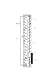
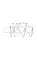
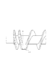
次に本特許の特徴であるAスクリューについて説明する。本実施例ではAスクリューは、図26に示すように螺旋状のスクリューと軸より構成されており、端部は図1で示すように、搬送スクリュー部(第1の搬送翼部)aと返しスクリュー部(第2の搬送翼部)bからなる。そして、搬送スクリュー部aと逆スクリュー部bを接合してもうけたことで、現像スリーブへの現像剤の供給不良を抑制することができた。 Next, the A screw characteristic of this patent will be described. In this embodiment, the A screw is composed of a spiral screw and a shaft as shown in FIG. 26, and the end is returned to a conveying screw portion (first conveying wing portion) a as shown in FIG. It consists of a screw part (second conveying blade part) b. Further, since the conveying screw portion a and the reverse screw portion b are joined, the supply failure of the developer to the developing sleeve can be suppressed.
次に本発明者は、更なる検討を進め、図に示すように、その2つのスクリュー部で囲まれた三角形状領域の一部に底上げ部を設けている(溝を有さない形状にした)。即ち、三角形状領域の一部をAスクリューの他の領域の軸部よりも底上げした形状とし、現像剤の供給不良を高レベルで抑制することができた。 Next, the present inventor has further studied, and as shown in the figure, a bottom raised portion is provided in a part of the triangular region surrounded by the two screw portions (the shape has no groove). ). That is, a part of the triangular region was shaped so as to be raised from the shaft portion of the other region of the A screw, and the supply failure of the developer could be suppressed at a high level.
なお、以下において、図28に示すスクリューを比較例として説明するが、この図28に示すスクリューの構成は上述したように本発明の適用範囲であり、更なる改良と捉えて説明する。比較例を用いた場合、図6に示すようにハーフトーン画像、べた画像をとると端部のAスクリューの搬送スクリューと逆スクリューの接合する部分で白抜け現象が少ない割合で生じることがあった。 In the following, the screw shown in FIG. 28 will be described as a comparative example. However, the configuration of the screw shown in FIG. 28 is within the scope of the present invention as described above, and will be described as further improvements. When a comparative example is used, as shown in FIG. 6, when a halftone image or a solid image is taken, a white spot phenomenon may occur at a small ratio at a portion where the conveying screw of the A screw at the end and the reverse screw are joined. .
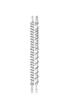
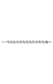
これは、(1)長手方向において現像領域内に搬送スクリューと逆スクリューの結合部があること、(2)この結合部の現像スリーブとは反対側の位置に仕切り壁が存在しにないこと、によりAスクリュー部からBスクリュー部へ現像剤が流れてしまい、現像剤の剤面が下がり不安定な状態になることから生じたと思われる(図2)。 This is because (1) there is a connecting portion of the conveying screw and the reverse screw in the developing region in the longitudinal direction, and (2) there is no partition wall at a position opposite to the developing sleeve of the connecting portion, This is considered to be caused by the fact that the developer flows from the A screw portion to the B screw portion and the developer surface of the developer is lowered and becomes unstable (FIG. 2).
本実施例ではAスクリューピッチを15mm、Bスクリューピッチを24mmとして、Aスクリュー側の剤面を適正にした。Aスクリュー、Bスクリュー各々の形状はφ18mmで図26と図27に示すとおりである。 In this example, the A screw pitch was 15 mm, the B screw pitch was 24 mm, and the surface of the A screw was made appropriate. The shape of each of the A screw and the B screw is φ18 mm, as shown in FIGS.
本Aスクリューの特徴は図21と図22を比べてわかるように、現像剤を搬送方向に移動させる搬送スクリューと現像剤搬送方向最下流部にスクリューと現像剤の進行方向が逆向きな逆スクリューを有し、搬送スクリュー部と逆スクリュー部は接合していると共に、2つのスクリューで囲まれた三角形状領域の空間が底上げされていることである。 As can be seen from the comparison between FIG. 21 and FIG. 22, the present A screw has a conveying screw that moves the developer in the conveying direction, and a reverse screw that has the screw and developer moving in opposite directions at the most downstream portion in the developer conveying direction. The conveying screw portion and the reverse screw portion are joined together, and the space in the triangular region surrounded by the two screws is raised.
表1に接合部の構成としてAからDまでの4つの構成をしめす。これらの構成をしたAスクリューでハーフトーン及びべた画像を出した際の端部の白抜けレベルはA 結合部がないもの(3−5mmgap)、B 結合したもの、C 結合角を振ったもの(30−50度)ではいずれも白抜けが発生してしまった。結合角をふる際には、スクリューのピッチを30mmまでしてみた。更に、スクリュー回転数を50−300r.p.m.で振ってみたが、いずれもNGであった。また、現像剤量に対しても、剤の汲み上げがし易いように、本構成で適正である、250gから更に50gアップさせてみたが、いずれもNGであった。その一例を表2に示す。スクリューのピッチに関しても、白すじはピッチに依存しないことがわかる。 Table 1 shows four configurations from A to D as the configuration of the joint. When the half-tone and solid images are produced with the A screw having the above structure, the whiteout level of the end portion is the one without the A coupling portion (3-5 mm gap), the one coupled with the B coupling, the one with the C coupling angle shaken ( In all cases (30-50 degrees), white spots have occurred. When squeezing the bonding angle, the screw pitch was set to 30 mm. Furthermore, the screw rotation speed is 50-300 r. p. m. I tried to shake it, but all were NG. Further, the developer amount was further increased from 250 g, which is appropriate in the present configuration, so that the agent could be easily pumped up, but both were NG. An example is shown in Table 2. As for the pitch of the screw, it can be seen that the white stripe does not depend on the pitch.
これに対して、Dのように、搬送スクリューと逆スクリューで囲まれた三角形状領域を埋めて、底上げした状態にした構成では、ハーフトーン、べた画像とも、白すじは発生しなかた。構成の詳細は図20に示すように、スクリュー先端部の幅は2mm、溝のない部分の幅は内側で6mm、外側で8mmである。底上げした部分の半径方向の幅は12mmである。 On the other hand, in the configuration in which the triangular area surrounded by the conveying screw and the reverse screw is filled and the bottom is raised as shown in D, no white lines are generated in the halftone and solid images. As shown in FIG. 20, the details of the configuration are as follows. The width of the screw tip is 2 mm, and the width of the portion without the groove is 6 mm on the inside and 8 mm on the outside. The width of the raised portion in the radial direction is 12 mm.
次に、白すじが端部ででる理由及び本実施ででない理由について述べる。 Next, the reason why white streaks appear at the end and the reason why they are not in this embodiment will be described.
1 搬送スクリューと逆スクリュー部と接合部では、ピッチ幅が、図21に示すように、大きくなり、φ15mmのピッチに対して幅21mmとなり、本来スクリューで埋めている空間が空くために、現像剤の剤面が下がり、スリーブに対する剤の供給能力が低下する。更には現像スリーブと反対側には仕切り壁がないため、現像剤はBスクリュー側に流れてしまう。そのため、この部分に局所的なコート不良が起こり、白抜け画像になる。 1 In the conveying screw, the reverse screw portion, and the joining portion, the pitch width is increased as shown in FIG. 21, and the width is 21 mm with respect to the pitch of φ15 mm, and the space originally filled with the screw is vacant. As a result, the surface of the material is lowered, and the ability to supply the agent to the sleeve is lowered. Furthermore, since there is no partition wall on the side opposite to the developing sleeve, the developer flows to the B screw side. For this reason, a local coating defect occurs in this portion, resulting in a whiteout image.
2 搬送Aスクリューは通常、スリーブ下方にあり、一度汲み上げられた現像剤は通常搬送スクリューと逆スクリューの間に挟まれた空間(溝)に落ちるが、本特許のように底上げした形にすることで、剤面が下がらない状態に保てる。 2 The conveying A screw is usually located under the sleeve, and the developer once pumped up usually falls into a space (groove) sandwiched between the conveying screw and the reverse screw, but it should be raised at the bottom as in this patent. And it can be kept in a state where the surface of the agent does not fall.
3 本特許のように底上げすることで図24に示すように、剤を現像スリーブに供給する面Sを作り、供給面を増すとともに、その後、底上げしていることで剤面が落ちるのを防いでいる。回転方向については、図24で示す現像剤供給面が上流になるように、矢印の向きに回転させる。 3. As shown in FIG. 24, by raising the bottom as in this patent, a surface S for supplying the agent to the developing sleeve is created, the supply surface is increased, and then the bottom is raised to prevent the agent surface from falling. It is out. As for the rotation direction, the developer supply surface shown in FIG. 24 is rotated in the direction of the arrow so that it is upstream.
このような、理由により本発明では、画像白すじをなくすことができた。溝無し部の体積については、表3に示すように、白すじレベルの比較より、20mm3以上が好ましい。これは先に述べた理由のため、効果を得るためには、ある程度の容積が必要であるためである。 For this reason, the present invention can eliminate image white streaks. About the volume of a groove-less part, as shown in Table 3, 20 mm3 or more is preferable from the comparison of a white stripe level. This is because a certain amount of volume is required to obtain the effect for the reason described above.
次に、Bスクリューについて述べる。 Next, the B screw will be described.
本実施ではBスクリューは径18mmで形状はBスクリューが図27に示すような補給部より剤の搬送方向下流にフィンを設けない領域を設け、その下流にフィンをスクリュー軸の周状に放射状に20個設けた構成にした。AスクリューとBスクリューの組み合わせとしては図10にしめすとうりである。スクリューを軸中心からみると4つのフィンがついた構成とした。Aスクリューはフィンがない形状にした。軸径はBスクリューと同じである。スクリュー軸径は8mmである。フィンの形状は図20に示すように、幅5mmのものにした。 In the present embodiment, the B screw has a diameter of 18 mm and the shape is such that the B screw is provided with a region where no fin is provided downstream of the replenishment portion as shown in FIG. 27, and the fin is radially arranged around the screw shaft. It was set as the structure which provided 20 pieces. The combination of the A screw and the B screw is shown in FIG. When the screw is viewed from the axial center, it has a configuration with four fins. The A screw was shaped without fins. The shaft diameter is the same as the B screw. The screw shaft diameter is 8 mm. The shape of the fin was 5 mm wide as shown in FIG.
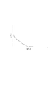
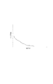
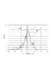
従来のBスクリューは軸と螺旋状のスクリューよりなるものや、図29に示すような、軸とスクリューに加え複数のフィンを設けたものが主流である。剤面に関しては一般にはスクリュー内の剤面はほぼ水平にした方が良いと従来考えられていた。そこで、AスクリューとBスクリューの1 ピッチを変える、2 回転数を変える等をして循環のバランスを変えて剤面の調整をしている。しかし、図2のように、小型現像器においては、補給口から現像スリーブへ至るまでの撹拌長が短いために、十分、キヤリアとトナーを攪拌できなかった。具体的には10k耐久においてべた画像をとると画像かぶりは許容値2%に対して5%であった。通常べた画像コピーでは大量なトナーが現像器へ入るため、撹拌が一番厳しい。図15に撹拌長と飛散トナーの関係、図17に撹拌長と画像かぶりの関係を定性的に示す。このように撹拌長が短ければ短いほど飛散、かぶりとも悪くなる。現像器の小型化によりこの撹拌長はますます短くなり、許容の飛散量、かぶりを越えてしまう。この理由として図18にトナーの帯電付与性について説明する。これはトナー帯電量分布を表す。横軸は帯電量で右側がプラス、左側がマイナスである。本件のトナーは負極性であるので0よりマイナス側が好ましい。破線は耐久後のトナーの帯電量分布で実線は初期の帯電量分布である。測定ポイントはBスクリューからAスクリューへ剤を受けわたす部分である。2つのピークがあり0近傍に大きなピークができていることがわかる。すなわち帯電が不十分トナーが多い。このように帯電付与が十分できていないために、上記、飛散、かぶりが生じるのである。 Conventional B screws are mainly composed of a shaft and a spiral screw, or those provided with a plurality of fins in addition to the shaft and screw as shown in FIG. Conventionally, it has been conventionally considered that the surface of the screw should be almost horizontal. Therefore, by changing one pitch of the A screw and the B screw, changing the number of rotations, etc., the balance of circulation is changed to adjust the surface of the material. However, as shown in FIG. 2, in the small developing device, since the stirring length from the replenishing port to the developing sleeve is short, the carrier and the toner cannot be sufficiently stirred. Specifically, when a solid image was taken at 10k durability, the image fog was 5% against the allowable value of 2%. In a solid image copy, a large amount of toner enters the developing device, so stirring is the most severe. FIG. 15 qualitatively shows the relationship between stirring length and scattered toner, and FIG. 17 shows the relationship between stirring length and image fog. Thus, the shorter the stirring length, the worse the scattering and fogging. Due to the downsizing of the developing device, the stirring length becomes shorter and exceeds the allowable scattering amount and fog. The reason for this is described with reference to FIG. This represents the toner charge amount distribution. The horizontal axis is the charge amount, the right side is positive and the left side is negative. Since the toner of the present case has a negative polarity, a negative side of 0 is preferable. The broken line is the charge amount distribution of the toner after the endurance, and the solid line is the initial charge amount distribution. The measurement point is the part that passes the agent from the B screw to the A screw. It can be seen that there are two peaks and a large peak is formed near zero. That is, there is much toner with insufficient charging. As described above, since charging is not sufficiently performed, the above-described scattering and fogging occur.
本件では図27のようなスクリューをBスクリューに用いることでトナー補給口部での剤の高さを低くし、供給トナーを撹拌スクリュー軸中心に取り込むとともに、搬送方向下流部で最大限撹拌させるためにスクリュー軸に撹拌用フィンを放射状につけ、撹拌性、帯電付与性を向上させた。補給口部での剤面を下げることはAスクリュー最下流部の剤面を下げることでも有り、このような状態においても、現像スリーブへの現像剤コート性を維持し、白すじ画像を出さないためにも、上記で述べたAスクリュー形状は重要である。Bスクリューの剤面については、トナー補給部近傍とその下流で剤面は段差が生じる。この段差の上流がトナー取り込み、下流が撹拌upという機能分離化型撹拌スクリューとなる。その結果、画像上かぶりは10k耐久後にべた画像10枚後でも1%と格段によくなる。実際の画像も長手方向でむらが生じることがなく、均一な画像を形成することができた。その理由として、実際にトナーの帯電量分布を測定すると図19に示すように実線(初期)も破線(10k耐久後)も未帯電トナーを減らすことができている。 In this case, the screw as shown in FIG. 27 is used as the B screw to lower the height of the agent at the toner replenishing port portion, to take in the supplied toner into the center of the stirring screw shaft and to stir at the maximum in the downstream portion in the transport direction. In addition, stirring fins were radially attached to the screw shaft to improve the stirring property and charge imparting property. Lowering the agent level at the replenishing port also means lowering the agent level at the most downstream part of the A screw. Even in such a state, the developer coatability to the developing sleeve is maintained and no white streak image is produced. For this reason, the A screw shape described above is important. Regarding the surface of the B screw, there is a difference in level between the surface of the toner supply portion and the downstream thereof. A function-separated type agitation screw in which toner is taken in upstream of the step and agitation up is downstream is used. As a result, the fog on the image is remarkably 1% even after 10 solid images after 10k durability. The actual image was not uneven in the longitudinal direction, and a uniform image could be formed. The reason is that when the toner charge amount distribution is actually measured, the uncharged toner can be reduced in both the solid line (initial stage) and the broken line (after 10 k endurance) as shown in FIG.
トナーの取り込みに関して本件では補給口直下に1個のフィンを設け、取り込みに関して安定させた。多数のフィンを設けると剤面があがるためこのましくなく、直下には2個以下にするのが好ましい。以上の構成にすることで50k耐久および低湿、高湿環境においても画像かぶりとしては最大1.2%以下に抑えることができた。 Regarding toner uptake, in this case, a single fin was provided immediately below the supply port to stabilize the uptake. If a large number of fins are provided, the surface of the material rises, so this is not preferable. With the above configuration, the image fogging can be suppressed to a maximum of 1.2% or less even in a 50k durability, low humidity, and high humidity environment.
以上のように、小型2成分現像装置において端部での現像剤の現像剤担持体への供給を確実に行い、現像剤のコート不良や画像白抜けを防止すると共に、トナーの撹拌不良を防ぎ、トナーの帯電性を維持することで飛散、かぶりを防止し、画像むらのない高画質画像を提供することができた。 As described above, in the small two-component developing device, the developer is surely supplied to the developer carrier at the end portion to prevent the developer from being poorly coated and the image from being white, and to preventing the toner from being agitated. By maintaining the chargeability of the toner, it was possible to prevent scattering and fogging and provide a high-quality image without image unevenness.
本発明にかかる現像装置は図12に示す。 A developing device according to the present invention is shown in FIG.
本実施例の特徴は高速リユース画像形成装置に本発明の現像装置を適用したことである。リユース系トナーは基本的には転写されずに残りクリーニングで回収された廃トナーであるために、劣化でNewトナーと比較して、廃トナーは凝集度が高く、帯電量も変化するために新トナーと旧トナーで剤面が変化しやすい。また、高速機は単位時間に対する現像スリーブの回転数が早いため、現像剤の現像スリーブへのコートも難しい。本実施例はこれらのことを鑑みて実施したものである。本実施例で用いたAスクリューは搬送スクリューと逆スクリューの結合部で形成される三角形状部を実施例1に対して、スクリューの半径方向に更に。0.5mm外側に突き出した構成にした。(図示せず)その他の部分のスクリューと現像器の底面との距離は1.5mmである。このようにすることで、更に結合部での局所的な剤面を上げるともに、図24で示された面Sの面積も増やすことで現像スリーブへの現像剤の供給能力をアップさせた。Bスクリューに関しては実施例1と同様な構成にした。 The feature of this embodiment is that the developing device of the present invention is applied to a high-speed reuse image forming apparatus. Since the reuse toner is basically waste toner that is not transferred and collected by cleaning, the waste toner has a higher degree of aggregation and changes the charge amount compared to the New toner due to deterioration. The surface of the toner is likely to change between the toner and the old toner. In addition, since the high speed machine has a high rotation speed of the developing sleeve per unit time, it is difficult to coat the developing sleeve with the developer. The present embodiment was implemented in view of these matters. The A screw used in the present example is a triangular part formed by the coupling part of the conveying screw and the reverse screw, and further in the radial direction of the screw with respect to the first example. The configuration protruded 0.5 mm outward. (Not shown) The distance between the screw in the other part and the bottom surface of the developing device is 1.5 mm. In this way, the local agent surface at the joint is further increased, and the area of the surface S shown in FIG. 24 is increased, thereby increasing the developer supply capability to the developing sleeve. The B screw had the same configuration as in Example 1.
本実施例では図12に示す画像形成システムで感光体としてOPCドラムを用いたデジタル複写機について説明する。プロセススピードは500mm/sの110枚/分である。この感光ドラム201の表面を、一次帯電器203により−700Vに一様帯電する。ついで、波長680μmの半導体レーザーで600dpiでPWMによる露光212を行って、感光ドラム201上に静電潜像を形成する。次に、現像器202により反転現像し、トナー像として可視化する。現像剤は2成分現像を行い、ネガトナーを用いた反転現像をする。トナー粒径は8.0μmである。現像バイアスは周波数2400Hz、交流で電圧1500Vpp、Duty50%の交流電圧に+200Vの直流電圧を重畳したバイアス電圧を印加する。S−Bgapは350μm、でS−Dgapは350μmとした。その後、ポスト帯電器で総電流−200μA流してトナー像を帯電させた後、矢印方向に進む転写材に転写帯電器204により転写し、定着器7に送ってトナー像を定着する。一方、感光ドラム1上の転写残りのトナーをクリーニング装置206により除去、回収して搬送パイプ208を通して廃トナー(リユーストナー)を現像ホッパー209Bに戻す。搬送パイプにはスクリュー状の搬送部材が内部にあり、回転することでリユーストナーを運ぶ。更に詳細を述べると図12に示すように運ばれたリユーストナーは現像ホッパー209Bに入れられ再利用される。また別にNewトナーはホッパー209Aに入れられ、ローラが回転することにより現像器内にトナーは運ばれる。本実施例ではリユーストナーとNewトナーを現像器内で混ぜる方法を採用したが、ホッパー内に混合するスペースを設け混ぜても構わない。現像器内で混ぜられたトナーは再び現像スリーブに送られ、感光体上に現像される。供給ローラの通常の回転速度は2回転/分でローラの回転速度を変化させる。補給量は画像データ(ビデオカウント)によりローラ回転を制御する。
In this embodiment, a digital copying machine using an OPC drum as a photoreceptor in the image forming system shown in FIG. 12 will be described. The process speed is 110 mm / min at 500 mm / s. The surface of the
廃トナーが混在した補給トナーは凝集度が通常10%程度に対して3倍程度となっているコート性、トナーの帯電付与性に不利な高速リユース複写機において、耐久試験をした。本構成にした際のハーフトーン画像、べた画像について、100枚の耐久を通して確認をしたところ、初期から耐久後に至るまで、白抜け画像のない均一な画像を維持することができた。また、画像かぶりに関しても、従来は50kの耐久後でべた画像を10枚とった後のかぶりは8%と悪く製品化が困難だったのに対して、本実施例では1.5%程度に抑えることができた。 The replenishment toner mixed with waste toner was subjected to an endurance test in a high-speed reuse copier, which is disadvantageous in terms of coatability and toner chargeability, in which the degree of aggregation is usually about 3 times that of about 10%. When the halftone image and the solid image in this configuration were checked through the durability of 100 sheets, a uniform image with no blank images could be maintained from the initial stage to the end of the durability period. Also, with regard to image fogging, the fogging after taking 10 images after 50k endurance was 8% and it was difficult to produce a product, whereas in this example, it was about 1.5%. I was able to suppress it.
以上の構成にすることで、トナーリユース小型現像装置においても小型2成分現像装置において端部での現像剤の現像剤担持体への供給を確実に行い、現像剤のコート不良や画像白抜けを防止すると共に、トナーの撹拌不良を防ぎ、トナーの帯電性を維持することで飛散、かぶりを防止し、画像むらのない高画質画像でかつ廃棄物を出さないという点で、環境に優しい現像装置を提供することができた。 With the above configuration, even in the toner-reusing small-sized developing device, the developer is reliably supplied to the developer carrying member at the end in the small two-component developing device, and the developer coating defect and the image blank are prevented. In addition to preventing toner agitation, maintaining toner chargeability to prevent scattering and fogging, high-quality images with no image unevenness, and no waste, environmentally friendly development device Could be provided.
本件は小型現像器においてトナー補給口下流に現像剤を現像器より外に出す構成をとる場合である。これは2成分現像の現像剤の剤寿命を長寿命化するため、補給するトナーにあらかじめキヤリアを少量混ぜるとともに、現像器内の劣化したキヤリアを現像器外へ排出し、結果として劣化したキヤリアを含む剤が新しい剤と入れ替わるので、現像剤そのものの寿命を延ばすことができるシステムである。本実施例ではそのような長寿命化を図った現像器において実施した。このようなシステムの場合、現像剤の量自体も変化するため、更に現像スリーブへの現像剤の供給も不安定になる。また、長寿命になる分、寿命に近い枚数まで、現像剤のコートを安定化させ、均一画像を維持することが難しくなる。 This case is a case where a small developer is configured to take the developer out of the developer downstream of the toner supply port. In order to prolong the life of the developer in the two-component development, a small amount of carrier is mixed in advance with the toner to be replenished, and the deteriorated carrier in the developing device is discharged out of the developing device. As a result, the deteriorated carrier is removed. Since the contained agent is replaced with a new agent, the system can extend the life of the developer itself. In the present embodiment, the development was performed in such a developing device with a long life. In such a system, since the amount of the developer itself changes, the supply of the developer to the developing sleeve becomes unstable. Further, as the life becomes longer, it becomes difficult to stabilize the developer coat and maintain a uniform image up to the number close to the life.
本実施例では画像形成装置、現像器の基本構成は実施例1と同様である。図8において現像剤の回収口を長手方向でP0領域に設ける。このような場合、現像剤排出口近傍の剤面は排出口の最上点より高くなければいけない。これは剤面が低いとキヤリアを含んだ補給現像剤が蓄積されても排出されないためである。なお、本実施例の排出方法は搬送スクリューが回転することで剤が動き排出動作がされことを利用する。開口部が15mm×5mmとして排出口を図8のP0領域でおけ底からの高さを19mmにし、現像剤量を振った際の排出特性を図14に示す。現像剤が増えてくると所定高さ以上の現像剤が排出されるしくみである。横軸は現像器内の現像剤量である。べた画像をとり続けた場合、補給現像剤中のキヤリアが急激に現像器内に入る。その際に現像機内が蓄積した現像剤でまんぱんにならないように所定時間で所定量排出する必要がある。本実施例では補給剤中のキヤリアの比率は重量比で20%とした。べた画像連続時に必要な排出量は200mgである。この量以下だとまんぱんになる。この点を鑑み図17をみると実施例では現像剤量280gで300mg排出している。従って、通常の現像剤の剤面の振れに対して更には30g程度、変動要因が加わることとなる。したがって、このような系では従来、画像白すじレベルは更に悪かったのであるが、本実施例のスクリューを用れば、端部の画像白抜け画像も300kの耐久を通してなく、本実施例では現像剤の寿命としては通常50k枚程度に対して、300kの寿命を達成させることができた。また、このような現像剤面の制約を受けても、補給トナーを十分に撹拌できるため、耐久によってもかぶりのない高画質を維持することができた。 In this embodiment, the basic configurations of the image forming apparatus and the developing device are the same as those in the first embodiment. In FIG. 8, a developer recovery port is provided in the P0 region in the longitudinal direction. In such a case, the surface of the developer near the developer discharge port must be higher than the highest point of the discharge port. This is because if the surface of the developer is low, even if the replenishment developer containing the carrier is accumulated, it is not discharged. Note that the discharging method of the present embodiment utilizes the fact that the agent moves and is discharged as the conveying screw rotates. FIG. 14 shows the discharge characteristics when the opening is 15 mm × 5 mm, the discharge port is in the P0 region of FIG. 8 and the height from the bottom is 19 mm, and the developer amount is varied. When the developer increases, the developer having a predetermined height or more is discharged. The horizontal axis represents the amount of developer in the developing device. When the solid image is continuously taken, the carrier in the replenishment developer suddenly enters the developing device. At that time, it is necessary to discharge a predetermined amount in a predetermined time so that the developer accumulated in the developing machine does not become full. In this example, the carrier ratio in the replenisher was 20% by weight. The discharge amount required for continuous solid images is 200 mg. If it is less than this amount, it will become a lot. In view of this point, FIG. 17 shows that 300 mg is discharged at a developer amount of 280 g in the embodiment. Therefore, a fluctuation factor of about 30 g is further added to the fluctuation of the surface of the normal developer. Therefore, in such a system, the image white streak level has been worse in the past, but if the screw of this embodiment is used, the image blank image at the end portion does not pass through the endurance of 300 k, and in this embodiment, the development is not possible. As for the life of the agent, it was possible to achieve a life of 300 k against about 50 k normally. Even when the developer surface is restricted, the replenished toner can be sufficiently agitated, so that high image quality without fogging can be maintained even with durability.
以上説明したように現像装置の小型化を図った際にも、端部での現像剤の現像剤担持体への供給を確実に行い、現像剤のコート不良や画像白抜けを防止することができ、更に、トナーの撹拌不良を防ぎ、トナーの帯電性を維持することで飛散、かぶりを防止し、画像むらのない高画質画像を提供することができた。 As described above, even when the developing device is downsized, it is possible to reliably supply the developer to the developer carrying member at the end portion to prevent the developer from being poorly coated and the image blanking. In addition, it was possible to prevent poor stirring of the toner and maintain toner chargeability to prevent scattering and fogging, and to provide a high-quality image without image unevenness.

1 現像器
2 現像器ロータリ
3 ドラム
4 1次帯電ローラ
6 クリーニング装置
8 中間転写ベルト
9 1次転写ローラ
10 2次転写ローラ
40 現像器
41 現像スリーブ
44 Aスクリュー
45 Bスクリュー
50 現像スリーブ
60 現像器
DESCRIPTION OF SYMBOLS 1
Claims (2)
前記現像容器内の現像剤を収納する現像室と、
前記現像室と循環経路を形成し、前記現像容器内の現像剤を攪拌する攪拌室と、
前記現像室と前記攪拌室を仕切る仕切り部と、
前記現像室内の現像剤を担持して像担持体と対向する現像領域へ現像剤を搬送する現像剤担持体と、
前記現像剤担持体と対向して設けられ、前記現像剤担持体へ現像剤を供給するとともに、前記現像室内の現像剤を前記攪拌室に向けて搬送する搬送部材と、を有する現像装置であって、
前記搬送部材は、回転可能な回転軸と、前記回転軸上に螺旋状に形成され、現像剤を循環方向へ搬送する第1の搬送翼部と、前記回転軸上に螺旋状に形成され、現像剤を循環方向とは逆方向へ搬送する第2の搬送翼部と、を有する現像装置において、
現像剤の循環方向に関して前記現像室から前記攪拌室へ連絡する連絡路は、前記現像領域と重なる領域を有し、前記第1の搬送翼部と前記第2の搬送翼部は、前記連絡路と対向する位置において、互いの螺旋状の搬送翼部同士が直接結合されており、前記第1の搬送翼部と前記第2の搬送翼部が結合することで形成された空間の少なくとも一部を底上げした領域が設けられていることを特徴とする現像装置。 A developer container containing a developer in which toner and carrier are mixed;
A developing chamber for storing the developer in the developing container;
A stirring chamber for forming a circulation path with the developing chamber and stirring the developer in the developing container;
A partition for partitioning the developing chamber and the stirring chamber;
A developer carrying member that carries the developer in the developing chamber and conveys the developer to a developing region facing the image carrying member;
A developing device that is provided opposite to the developer carrying member, supplies a developer to the developer carrying member, and conveys the developer in the developing chamber toward the stirring chamber. And
The conveyance member is formed in a spiral shape on the rotation shaft, a first conveyance blade portion that is spirally formed on the rotation shaft , and conveys the developer in the circulation direction, and a spiral shape on the rotation shaft, In a developing device having a second conveying blade for conveying the developer in a direction opposite to the circulation direction,
The communication path that communicates from the developing chamber to the stirring chamber with respect to the developer circulation direction has an area that overlaps the developing area, and the first conveying blade section and the second conveying blade section are connected to the communication path. And at least a part of a space formed by coupling the first and second conveying blades to each other at a position opposite to each other. A developing device characterized in that a region with a raised bottom is provided.
Priority Applications (1)
| Application Number | Priority Date | Filing Date | Title |
|---|---|---|---|
| JP2003330065A JP4416463B2 (en) | 2003-09-22 | 2003-09-22 | Development device |
Applications Claiming Priority (1)
| Application Number | Priority Date | Filing Date | Title |
|---|---|---|---|
| JP2003330065A JP4416463B2 (en) | 2003-09-22 | 2003-09-22 | Development device |
Publications (3)
| Publication Number | Publication Date |
|---|---|
| JP2005099144A JP2005099144A (en) | 2005-04-14 |
| JP2005099144A5 JP2005099144A5 (en) | 2006-11-09 |
| JP4416463B2 true JP4416463B2 (en) | 2010-02-17 |
Family
ID=34459145
Family Applications (1)
| Application Number | Title | Priority Date | Filing Date |
|---|---|---|---|
| JP2003330065A Expired - Fee Related JP4416463B2 (en) | 2003-09-22 | 2003-09-22 | Development device |
Country Status (1)
| Country | Link |
|---|---|
| JP (1) | JP4416463B2 (en) |
Cited By (1)
| Publication number | Priority date | Publication date | Assignee | Title |
|---|---|---|---|---|
| CN102736480A (en) * | 2011-03-30 | 2012-10-17 | 佳能株式会社 | Developing device |
Families Citing this family (7)
| Publication number | Priority date | Publication date | Assignee | Title |
|---|---|---|---|---|
| JP5059356B2 (en) * | 2006-08-03 | 2012-10-24 | 株式会社リコー | Developing device, process cartridge, and image forming apparatus |
| JP4980775B2 (en) * | 2007-04-04 | 2012-07-18 | 株式会社リコー | Developing device and image forming apparatus |
| JP2008268506A (en) | 2007-04-19 | 2008-11-06 | Fuji Xerox Co Ltd | Developing device, image holding unit and image forming apparatus |
| JP5248307B2 (en) * | 2008-06-16 | 2013-07-31 | シャープ株式会社 | Developing device and image forming apparatus having the same |
| JP5430214B2 (en) * | 2009-04-27 | 2014-02-26 | キヤノン株式会社 | Development device |
| JP7205763B2 (en) * | 2019-02-18 | 2023-01-17 | 株式会社リコー | Developer Conveying Member, Developing Device, Process Cartridge, and Image Forming Apparatus |
| JP7465434B2 (en) * | 2019-09-25 | 2024-04-11 | 株式会社リコー | Developing device and image forming apparatus |
-
2003
- 2003-09-22 JP JP2003330065A patent/JP4416463B2/en not_active Expired - Fee Related
Cited By (1)
| Publication number | Priority date | Publication date | Assignee | Title |
|---|---|---|---|---|
| CN102736480A (en) * | 2011-03-30 | 2012-10-17 | 佳能株式会社 | Developing device |
Also Published As
| Publication number | Publication date |
|---|---|
| JP2005099144A (en) | 2005-04-14 |
Similar Documents
| Publication | Publication Date | Title |
|---|---|---|
| JP3919683B2 (en) | Development device | |
| US9405229B1 (en) | Developing device | |
| JP4289959B2 (en) | Image forming apparatus | |
| JP2005283685A (en) | Image forming apparatus | |
| JP4416463B2 (en) | Development device | |
| JP2006047886A (en) | Developing device, cartridge, and image forming apparatus | |
| JP2005315909A (en) | Image forming apparatus | |
| JPH0713420A (en) | Developing device | |
| JPH11133752A (en) | Image forming device | |
| JP3437512B2 (en) | Developing device | |
| JP2004151358A (en) | Image forming apparatus | |
| JP4129593B2 (en) | Image forming apparatus | |
| JP2000194194A (en) | Developing device and image forming device provided therewith | |
| JP2009163107A (en) | Image forming apparatus | |
| JP2005165149A (en) | Toner density detector and image forming apparatus | |
| JP2005017935A (en) | Development device and image forming apparatus using it | |
| JP2004093672A (en) | Developing device and image forming apparatus | |
| JP2005258149A (en) | Developing apparatus and image forming apparatus using the same | |
| JP2006119306A (en) | Developing device and image forming apparatus having the same | |
| JP4461848B2 (en) | Developing device and image forming apparatus using the same | |
| JPH08146757A (en) | Developing device | |
| JPH0546028A (en) | Image forming device | |
| JP2005195705A (en) | Image forming apparatus | |
| JP2006106218A (en) | Image forming apparatus | |
| JP2005031385A (en) | Developing device and image forming apparatus using the same |
Legal Events
| Date | Code | Title | Description |
|---|---|---|---|
| A521 | Written amendment |
Free format text: JAPANESE INTERMEDIATE CODE: A523 Effective date: 20060921 |
|
| A621 | Written request for application examination |
Free format text: JAPANESE INTERMEDIATE CODE: A621 Effective date: 20060921 |
|
| A977 | Report on retrieval |
Free format text: JAPANESE INTERMEDIATE CODE: A971007 Effective date: 20090212 |
|
| A131 | Notification of reasons for refusal |
Free format text: JAPANESE INTERMEDIATE CODE: A131 Effective date: 20090324 |
|
| A521 | Written amendment |
Free format text: JAPANESE INTERMEDIATE CODE: A523 Effective date: 20090522 |
|
| TRDD | Decision of grant or rejection written | ||
| A01 | Written decision to grant a patent or to grant a registration (utility model) |
Free format text: JAPANESE INTERMEDIATE CODE: A01 Effective date: 20091117 |
|
| A01 | Written decision to grant a patent or to grant a registration (utility model) |
Free format text: JAPANESE INTERMEDIATE CODE: A01 |
|
| A61 | First payment of annual fees (during grant procedure) |
Free format text: JAPANESE INTERMEDIATE CODE: A61 Effective date: 20091124 |
|
| R150 | Certificate of patent or registration of utility model |
Free format text: JAPANESE INTERMEDIATE CODE: R150 |
|
| FPAY | Renewal fee payment (event date is renewal date of database) |
Free format text: PAYMENT UNTIL: 20121204 Year of fee payment: 3 |
|
| FPAY | Renewal fee payment (event date is renewal date of database) |
Free format text: PAYMENT UNTIL: 20131204 Year of fee payment: 4 |
|
| LAPS | Cancellation because of no payment of annual fees |