JP5430214B2 - Development device - Google Patents
Development device Download PDFInfo
- Publication number
- JP5430214B2 JP5430214B2 JP2009107916A JP2009107916A JP5430214B2 JP 5430214 B2 JP5430214 B2 JP 5430214B2 JP 2009107916 A JP2009107916 A JP 2009107916A JP 2009107916 A JP2009107916 A JP 2009107916A JP 5430214 B2 JP5430214 B2 JP 5430214B2
- Authority
- JP
- Japan
- Prior art keywords
- developer
- conveying
- chamber
- screw
- rotary shaft
- Prior art date
- Legal status (The legal status is an assumption and is not a legal conclusion. Google has not performed a legal analysis and makes no representation as to the accuracy of the status listed.)
- Active
Links
Images


Landscapes
- Dry Development In Electrophotography (AREA)
Description
本発明は複写機、レーザプリンタ、ファクシミリ等の画像形成装置に装備される現像装置に関するものである。 The present invention relates to a developing device provided in an image forming apparatus such as a copying machine, a laser printer, and a facsimile machine.
図10〜図12は、従来の現像装置30を示す概略図である。図において、現像容器32内には、現像室14に設けられる第1現像剤攪拌搬送スクリュー5と、攪拌室15に設けられる第2現像剤攪拌搬送スクリュー36が設置される。これらスクリュー5,36により現像剤が攪拌混合され、また現像容器32内を搬送、循環される。現像剤の搬送方向は、図10の矢印Bおよび矢印C方向に搬送され、循環されている。
10 to 12 are schematic views showing a conventional developing
第1現像剤攪拌搬送スクリュー5と、第2現像剤攪拌搬送スクリュー36との間には隔壁7が設けられている。そして、現像剤の循環がスクリュー5,36間でスムーズに行なわれるように、図10に示すように隔壁7の奥側と手前側に現像剤受け渡し用の開口部7a,7bが設けられている。
A
つぎに、従来例の現像装置30の現像剤の補給回収について詳しく説明する。現像装置30の第2現像剤攪拌搬送スクリュー36の現像剤搬送方向下流側には図11に示すように、現像剤排出口8が設けられている。この現像剤排出口8と現像容器32との間には現像剤排出用の現像剤排出スクリュー9及び現像剤を押し戻す返しスクリュー10が設けられている。
Next, the replenishment and recovery of the developer in the conventional developing
また、補給現像剤として、トナー中に一定の割合(重量比にして10%程度)でキャリアを含んだ現像剤を使用している。比率はこれに限定されるものではない。画像形成によって消費された分のトナーは、前述したようにキャリアを一定の割合で含んだ補給現像剤として、図示しない補給スクリューの回転にしたがい、現像容器32の第2現像剤攪拌搬送スクリュー36の現像剤搬送方向上流側から補給される。この現像装置30への補給現像剤の補給は、補給現像剤ホッパー(図示せず)から行なわれ、現像容器32上側の補給口(図示せず)から受け取るものである。
Further, as the replenishment developer, a developer containing a carrier in a certain ratio (about 10% by weight) in the toner is used. The ratio is not limited to this. As described above, the toner consumed by the image formation is supplied to the second developer agitating and conveying
トナーおよびキャリアの補給量は、図示しない補給スクリューの回転数によっておおよそ定められるが、この回転数は図示しないトナー補給量制御手段によって定められる。 The replenishment amount of toner and carrier is roughly determined by the rotation speed of a replenishment screw (not shown), and this rotation speed is determined by a toner replenishment amount control means (not shown).
現像容器32内部の現像剤のトナー濃度を一定に保つように補給を行うと、現像容器32内の現像剤の量は画像形成にともなって増加する。補給現像剤はトナー90%、キャリア10%であるため、画像形成によってトナーは消費されるが、キャリアは消費されずに現像容器32内部に残り、補給が繰り返され現像剤量が増加してしまう。現像剤の量が増加した場合に、返しスクリュー10を現像剤が乗り越えて現像剤排出スクリュー9により現像剤排出口8に搬送される。現像剤排出口8に搬送された現像剤は、該現像剤排出口8から排出され、現像剤回収手段(図示せず)により回収容器(図示せず)に搬送されて、回収貯蔵される。
When replenishment is performed so that the toner density of the developer inside the developing
図13(a)を用いて説明すると、矢印Rのように現像剤は搬送されてきて、返しスクリュー10を乗り越え現像剤は排出スクリュー9によって排出される。また、図13(b)のH1は線上が通常の現像剤高さ、H2は現像剤高さが高くなり現像剤自動排出機能が働く現像剤高さとする。H1以上H2以下の現像剤が排出されるが、返しスクリュー10が存在するため、返しスクリュー10部以外の図13(b)に示す網掛け部S1のみからの排出となる。ただし、返しスクリュー10にはスクリュー終端部10bがあり、スクリュー終端部10bの位置により排出量が異なる構成である。例えば図13(b)に示すスクリュー終端部10bの位置は、現像剤自動排出機能が働く現像剤高さH2よりも低い位置にあるため排出されやすい位置となっている。また、図13(c)のように返しスクリュー終端部10bが現像剤高さH2よりも高い位置にある場合は、上記に説明したように消費されたトナー分が補給現像剤により補給される。同時に供給されたキャリアが過剰になった現像剤を排出しながら現像容器32の現像剤を一定に保つように2成分現像剤の入れ替えが自動的に徐々に行われ、現像剤自動排出機能を実現する。
Referring to FIG. 13A, the developer is conveyed as indicated by an arrow R, passes over the
以上のような現像剤自動排出構成が特開2002−72686号公報(特許文献1)にて提案されている。 Japanese Patent Laid-Open No. 2002-72686 (Patent Document 1) proposes an automatic developer discharging configuration as described above.
しかし、現像容器32内の攪拌搬送速度が常に一定であれば、上記の様に2成分現像剤の入れ替えが問題なく行われる。しかしながら、攪拌搬送速度が1/2速度や1/3速度といった複数の異なる攪拌搬送速度を同一現像装置30で行おうとした場合、第2現像剤攪拌搬送スクリュー36と返しスクリュー10の搬送力のバランスが崩れる。そして、返しスクリュー10の羽根の切れ目からこぼれ出して過剰な現像剤が排出されてしまう。図13は返しスクリュー10の羽根の切れ目から過剰な現像剤がこぼれ出す様子を示す。これにより、全ての攪拌搬送速度にて適切な現像剤排出量を確保することができないという問題点があった。
However, if the stirring and conveying speed in the developing
上記問題を言い換えると、十分な排出速度を得られない場合は、現像容器32内の現像剤が過剰になり現像剤詰まりや現像剤あふれを発生してしまう。また、逆に排出速度が高過ぎると現像剤が減りすぎてしまい、現像不良を発生させて被転写材に画像が載らなかったり、濃度が薄くなるといった問題が発生する。
In other words, if a sufficient discharge speed cannot be obtained, the developer in the developing
したがって、本発明の目的は、異なる搬送速度にて搬送れる現像剤の排出量を適切に制御することができる現像装置を提供することである。 Accordingly, an object of the present invention is to provide a developing device that can appropriately control the discharge amount of developer conveyed at different conveying speeds.
本発明に係る現像装置は、現像剤を担持する現像剤担持体を回転可能に支持するとともに、前記現像剤担持体に供給するための現像剤を収容する現像容器であって、現像剤を収容する第一室と、前記第一室と隔壁によって区画された第二室と、を備え、前記第一室と前記第二室とを両端部で互いに連絡することで現像剤を循環する循環路が形成された現像容器と、前記第二室の現像剤の搬送方向下流側の前記循環路外に設けられ、前記現像容器から現像剤を排出するための排出口と、前記第二室で回転可能に設けられた回転軸と、前記回転軸に設けられ、前記第二室の現像剤を循環方向に搬送するための螺旋状の第1搬送部と、前記第1搬送部の下流側で前記回転軸に設けられ、前記第1搬送部とは逆方向に現像剤を搬送する螺旋状の第2搬送部と、前記第2搬送部の搬送方向上流側で前記回転軸に設けられ、前記第2搬送部とは逆方向に搬送する螺旋状の第3搬送部と、を備えた搬送部材と、前記第2搬送部と前記第3搬送部との間で前記回転軸に設けられ、前記回転軸の周方向に沿って前記回転軸の径方向に突出し、前記回転軸の周方向に関して無端状に形成された突起部と、を有することを特徴とする。 A developing device according to the present invention, rotatably supports the developer carrying member for carrying a developer, a developer container for accommodating a developer to be supplied to said developer carrying member, containing a developer first chamber and circulating passage for circulating the developer by the a second chamber partitioned by the first chamber and the partition wall, provided with, communicate with each other at both ends and said second chamber and said first chamber to a developing container but formed, pre SL provided in the circulation path outside the downstream side of the second chamber of the developer, said a discharge port for discharging the developer from the developer container, in the second chamber A rotation shaft provided rotatably, a spiral first conveyance portion provided on the rotation shaft for conveying the developer in the second chamber in a circulation direction, and a downstream side of the first conveyance portion. A spiral second transport that is provided on the rotating shaft and transports the developer in a direction opposite to the first transport unit. And parts provided on the rotation axis in the conveying direction upstream side of the second conveyance unit, a conveying member having a third conveying section spiral for conveying in a direction opposite to the second transport unit, Provided on the rotary shaft between the second transport unit and the third transport unit , projecting in the radial direction of the rotary shaft along the circumferential direction of the rotary shaft, and endless in the circumferential direction of the rotary shaft And a protruding portion formed.
本発明によれば、異なる搬送速度にて搬送れる現像剤の排出量を搬送部材の第2搬送部と第3搬送部との間で回転軸に設けられ、回転軸の周方向に沿って該回転軸の径方向に突出し、該回転軸の周方向に関して無端状に形成された突起部により適切に制御することができる。 According to the present invention, provided on the rotary shaft between the second transport unit and the third transport portion of the transport member to discharge amount of the developer is conveyed at a different conveying speed along the circumferential direction of the rotary shaft Protrusions that protrude in the radial direction of the rotating shaft and that are formed endlessly in the circumferential direction of the rotating shaft can be appropriately controlled.
以下、この発明の実施の形態について説明する。 Embodiments of the present invention will be described below.
<画像形成装置の全体構成>
先ず、図1を用いて本発明に係る現像装置を備えた画像形成装置の一例として電子写真方式のプリンタの全体構成について説明する。図1は画像形成装置の全体構成説明図である。本実施形態の画像形成装置24は電子写真プリンタ(以下、単に「プリンタ」という)であり、画像情報に基づいて電子写真方式によりシートS上に未定着画像を形成する画像形成手段を有する。
<Overall configuration of image forming apparatus>
First, an overall configuration of an electrophotographic printer will be described with reference to FIG. 1 as an example of an image forming apparatus including a developing device according to the present invention. FIG. 1 is an explanatory diagram of the overall configuration of the image forming apparatus. The
画像形成手段は、電子写真方式によるものであり、帯電ローラ35へのバイアス印加によって表面を一様に帯電した画像形成手段となる感光ドラム29に、画像データに基づいて書き込み部37からレーザ光を照射して静電潜像を形成する。この静電潜像を現像装置1によりトナー現像して可視像化する。
The image forming means is based on an electrophotographic method, and a laser beam is applied from a
上記トナー像の形成と同期するように、装置本体31下部に装着されたシートカセット39に装填されたシートSを給送ローラ38、搬送ローラ33によって感光ドラム29と転写ローラ34のニップ部へ搬送する。そして、転写ローラ34へのバイアス印加によって感光ドラム29上のトナー像をシートSに転写して画像形成する。
The sheet S loaded in the
上記トナー像からなる未定着画像が転写されたシートSは定着ローラ41と加圧ローラ42とのニップ部に送られ、加熱、加圧されることによってトナー像が定着された後、排出ローラ45によって排出部44へと排出される。尚、本発明に係る現像装置1は、単色の画像形成装置やタンデム方式等の様々な方式でフルカラー画像形成をする画像形成装置について適用出来る。
The sheet S on which the unfixed image composed of the toner image is transferred is sent to the nip portion between the fixing
図2〜図6は、本発明の現像装置の第1実施形態の構成を示す概略図である。図2及び図3により現像装置1について詳しく説明する。現像装置1は、非磁性トナーと磁性キャリアからなる2成分現像剤を現像容器2内に収容しており、そのトナーとキャリアの混合比は重量比で1:9程度である。この比は、トナーの帯電量、キャリアの粒径、画像形成装置24の構成などで適正に調整されるべきものであって、必ずしもこの数値にしたがわなければならないものではない。
2 to 6 are schematic views showing the configuration of the first embodiment of the developing device of the present invention. The developing
現像装置1は、現像容器2の感光ドラム29に対向した現像領域の部分が開口しており、この開口部に一部露出するようにして、内部にマグネット4が非回転に配置された現像剤担持体となる現像スリーブ3が回転可能に設置されている。
The developing
現像スリーブ3は非磁性材料で形成され、現像動作時には図3の矢印A方向に回転し、現像容器2内の2成分現像剤を層状に保持して現像領域に搬送し、現像領域で感光ドラム29に現像剤を供給して、感光ドラム29上に形成されている静電潜像を現像する。潜像を現像した後の現像剤は、現像スリーブ3の回転にしたがって現像容器2内に回収される。
The developing
現像容器2内には、現像剤を収納可能な第一室となる現像室14と、該現像室14と連絡することで現像剤を循環させる循環路を形成し、現像剤を収納可能な第二室となる攪拌室15が設けられる。そして、現像室14及び攪拌室15内(第二室内)の現像剤を搬送する搬送手段となる第1、第2現像剤攪拌搬送スクリュー5,6が設けられている。そして、攪拌室15にトナーとキャリアを有する現像剤を補給するための図示しない補給口が設けられている。そして、図4に示すように、攪拌室15に設けられた現像剤を排出するための現像剤排出口8が設けられている。現像剤排出口8は第二室となる攪拌室15において現像剤の搬送方向下流側の循環路外に設けられる。そして、該現像剤排出口8よりも現像剤排出方向上流側に現像剤を堰き止めて排出量を制限する現像剤排出方向と交差する方向に連続する面で形成される現像剤排出量制限手段となる鍔部材11が第2現像剤攪拌搬送スクリュー6の回転軸10aに設けられている。回転軸10aは循環路と現像剤排出口8との間の現像剤搬送路中に回転可能に設けられる。そして、これらスクリュー5,6により2成分現像剤が攪拌混合され、現像容器2内を搬送、循環される。現像剤の搬送方向は、図2の矢印Bおよび矢印C方向に搬送され、循環されている。
In the developing
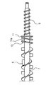
回転軸10aには現像剤排出口8に向かう現像剤を循環路に向けて搬送する螺旋状の搬送部となる排出スクリュー9が設けられている。そして、該排出スクリュー9の搬送方向上流部には該回転軸10aの周方向に連続して該回転軸10aの径方向に突出した環状の突起部となる鍔部材11が設けられている。鍔部材11は、その形状から攪拌室15に設けられた搬送手段となる第2現像剤攪拌搬送スクリュー6の回転数とは無関係に現像剤の排出量を制限する。
The
第1現像剤攪拌搬送スクリュー5と、第1現像剤攪拌搬送スクリュー6との間には隔壁7が設けられている。そして、現像剤の循環がスクリュー5,6間でスムーズに行なわれるように、図2に示すように隔壁7の奥側と手前側に現像剤受け渡し用の開口部7a,7bが設けられている。図3は、画像形成装置本体31の奥側から現像装置1を見た断面を示しており、図3の手前側が装置本体31の奥側に相当する。
A
つぎに、本実施形態の特徴的部分である現像剤の補給回収について詳しく説明する。図4に示すように、現像装置1の第2現像剤攪拌搬送スクリュー6の現像剤搬送方向下流側には現像剤排出口8が設けられている。この現像剤排出口8と現像容器2との間には図4〜図6に示すように、現像剤排出手段となる排出スクリュー9が設けられている。そして第2現像剤攪拌搬送スクリュー6と現像剤排出スクリュー9との間には逆搬送手段となる返しスクリュー10が設けられている。そして、返しスクリュー10の第2現像剤攪拌搬送スクリュー6による現像剤搬送方向下流側の終端部位置には現像剤排出量制限手段となる円形状の鍔部材11が設けられている。鍔部材11は、現像剤排出口8よりも現像剤排出方向上流側に現像剤を堰き止めて排出量を制限する現像剤排出方向と交差する方向に連続する面で形成される。
Next, the developer supply and recovery, which is a characteristic part of the present embodiment, will be described in detail. As shown in FIG. 4, a
第2現像剤攪拌搬送スクリュー6の2成分現像剤の搬送方向下流側に該第2現像剤攪拌搬送スクリュー6が設けられた2成分現像剤の搬送経路12に連続して2成分現像剤を排出する排出経路13が設けられている。排出経路13の底面13aの高さレベルは搬送経路12の底面12aの高さレベルよりも高いレベルに設定される。そして、該排出経路13に2成分現像剤の余剰分を現像剤排出口8に排出する現像剤排出スクリュー9が設けられている。
The two-component developer is continuously discharged to the two-component
第2現像剤攪拌搬送スクリュー6は、その2成分現像剤の搬送方向下流側にその2成分現像剤の搬送方向とは逆向きの搬送力を持った返しスクリュー10を有する。そして、返しスクリュー10の第2現像剤攪拌搬送スクリュー6による2成分現像剤の搬送方向下流側の終端部位置には2成分現像剤を堰き止めるために返しスクリュー10の軸10aの周囲に設けられた鍔部材11を有する。鍔部材11の第2現像剤攪拌搬送スクリュー6による2成分現像剤の搬送方向下流側には該第2現像剤攪拌搬送スクリュー6による2成分現像剤の搬送方向と同方向の搬送力を持った現像剤排出スクリュー9を有する。鍔部材11は、第2現像剤攪拌搬送スクリュー6の2成分現像剤の搬送方向から見て円形状で構成される。鍔部材11は、第2現像剤攪拌搬送スクリュー6の一部として構成される。
The second developer agitating and conveying
また、補給現像剤として、トナー中に一定の割合(重量比にして10%程度)でキャリアを含んだ現像剤を使用している。比率はこれに限定されるものではない。画像形成によって消費された分のトナーは、前述したようにキャリアを一定の割合で含んだ補給現像剤として、図示しない補給スクリューの回転にしたがい、現像容器2の第2攪拌搬送スクリュー6の現像剤搬送方向上流側から補給される。この現像装置1への補給現像剤の補給は、補給現像剤ホッパー(図示せず)から行なわれ、現像容器2上側の補給口(図示せず)から受け取るものである。
Further, as the replenishment developer, a developer containing a carrier in a certain ratio (about 10% by weight) in the toner is used. The ratio is not limited to this. As described above, the toner consumed by the image formation is used as a replenishment developer containing a carrier at a constant rate, and the developer of the second agitating and conveying
トナーおよびキャリアの補給量は、補給スクリューの回転数によっておおよそ定められるが、この回転数は図示しないトナー補給量制御手段によって定められる。 The amount of toner and carrier replenishment is roughly determined by the number of rotations of the replenishment screw, and this number of rotations is determined by a toner replenishment amount control means (not shown).
現像容器2内部の現像剤のトナー濃度を一定に保つように補給を行うと、現像容器2内の現像剤の量は画像形成にともなって増加する。補給現像剤はトナー90%、キャリア10%であるため、画像形成によってトナーは消費されるが、キャリアは消費されずに現像容器内部に残り、補給が繰り返されて現像剤量が増加してしまう。現像剤の量が増加した場合に、返しスクリュー10及び鍔部材11を現像剤が乗り越えて現像剤排出スクリュー9により現像剤排出口8に搬送される。現像剤排出口8に搬送された現像剤は、該現像剤排出口8から排出され現像剤回収手段(図示せず)により回収容器(図示せず)に搬送されて、回収貯蔵される。
When replenishment is performed so as to keep the toner density of the developer inside the developing
上記に説明したように消費されたトナー分が補給現像剤により補給され、同時に供給されたキャリアが過剰になった現像剤を排出しながら現像容器2の現像剤を一定に保つように2成分現像剤の入れ替えが自動的に徐々に行われ、現像剤自動排出機能を実現する。
As described above, two-component development is performed so that the consumed toner is replenished by the replenishment developer, and at the same time, the developer in the developing
次に本発明において特徴的である複数の攪拌搬送速度に対応する現像剤自動排出機能について説明する。現像剤攪拌搬送速度を例えば300rpm、150rpm、100rpmといった等速度、1/2速度、1/3速度と複数の搬送速度を持つ場合がある。この場合は、第2現像剤攪拌搬送スクリュー6により搬送され、返しスクリュー10の該第2現像剤攪拌搬送スクリュー6による現像剤搬送方向下流側の終端部(以下単に「終端部」という)10bにまで羽根の切れ目からこぼれて到達する現像剤量が変動する。
Next, an automatic developer discharging function corresponding to a plurality of stirring and conveying speeds that is characteristic in the present invention will be described. In some cases, the developer agitation conveyance speed has a plurality of conveyance speeds, for example, an equal speed such as 300 rpm, 150 rpm, and 100 rpm, a 1/2 speed, and a 1/3 speed. In this case, the developer is conveyed by the second developer agitating and conveying
現像剤搬送速度が等速度の場合は低速度の場合と比較して搬送速度が高速度となるため現像剤が持つ慣性力が大きくなり、等速度の方がより多くの現像剤が返しスクリュー10の羽根の切れ目からこぼれて終端部10bまで到達する。
When the developer transport speed is the same speed, the developer speed is higher than when the developer speed is low, so the inertial force of the developer increases. And spills from the cuts of the blades to reach the
しかし、返しスクリュー10の終端部10bに到達した現像剤は鍔部材11に衝突して減速されるため第2現像剤攪拌搬送スクリュー6により搬送されてきた現像剤の慣性力も低減して速度依存性も大きく減少する。また、鍔部材11は回転しているが、円盤形状であるため回転速度に依存されず常時、円盤形状の壁として遮蔽することができる。図14(a)を使って説明すると、矢印P方向に現像剤が進んでくるが、鍔部材11に衝突する。そして鍔部材11を矢印Qのように乗り越えた現像剤のみが排出スクリュー9に到達する。また、図14(b)のH1は線上が通常の現像剤高さ、H2は現像剤高さが高くなり現像剤自動排出機能が働く現像剤高さとする。現像剤はH1以上H2以下の高さにあるもののみが排出されるが、鍔部材11が存在するため現実には網掛け部S2の部分からのみの現像剤を排出することになり、第2現像剤攪拌搬送スクリュー6の回転による移相差の影響を受けない構成となる。したがって、現像剤搬送速度が等速度から1/3速度まで速度差に関係なく、鍔部材11を乗り越えて現像剤排出スクリュー9に到達する現像剤量が一定となり、現像剤排出口8からの現像剤排出量を一定とすることができる。
However, since the developer that has reached the
以上説明したように、本発明では現像容器2や第1現像剤攪拌搬送スクリュー5や第2現像剤攪拌搬送スクリュー6などの装置構成は同一構成とした。そして複数の攪拌搬送速度においても現像剤量を一定に保つことができる。
As described above, in the present invention, the apparatus configurations such as the
なお、排出スクリュー9の搬送方向上流部に設けられ、回転軸10aの周方向に連続して該回転軸10aの径方向に突出した環状の突起部としては、他の種々の形状が考えられる。例えば、現像剤排出方向上流側の一方が円錐面であっても良い。また、両側が円錐面(そろばんの玉の形状)であっても良い。また、球面形状であったり、回転軸方向に階段形状に徐々に径が大きくなる円柱、或いは円盤状であっても良い。また、円盤の一部に微細な孔が複数空いていても同様に適用可能である。
Note that provided in the transport direction upstream of the
次に図7〜図9を用いて本発明に係る現像装置の第2実施形態について説明する。図7は、本実施形態の現像装置を示す概略図である。図7〜図9により本実施形態の現像装置1について詳しく説明する。尚、前記第1実施形態と同様の構成については同一の符号を付して説明を省略する。
Next, a second embodiment of the developing device according to the present invention will be described with reference to FIGS. FIG. 7 is a schematic view showing the developing device of this embodiment. The developing
本実施形態では、排出スクリュー9の搬送方向上流部に設けられ、回転軸10aの周方向に連続して該回転軸10aの径方向に突出した環状の突起部として鍔部材21が設けられる。鍔部材21は2成分現像剤を堰き止めるために該返しスクリュー10の回転軸10a周囲で現像容器2の壁面に固定される。鍔部材21は現像剤排出口8の口径よりも小さい口径を有して構成される。本実施形態の鍔部材21には側面に脚部が設けられ該脚部が現像容器2の壁面に固定されたものである。現像容器2、現像剤自動排出機能については、前記第1実施形態と同様であるため、説明は省略する。
In the present embodiment, provided in the transfer direction upstream side of the
次に本実施形態の特徴的である複数の攪拌搬送速度に対応する現像剤自動排出機能について説明する。本実施形態の現像装置1のように、現像剤攪拌搬送速度を例えば300rpm、150rpm、100rpmといった等速度、1/2速度、1/3速度と複数の搬送速度を持つ場合がある。その場合は、第2現像剤攪拌搬送スクリュー6により搬送されて返しスクリュー10の終端部にまで到達する現像剤量が変動する。
Next, a developer automatic discharging function corresponding to a plurality of stirring and conveying speeds that is characteristic of the present embodiment will be described. As in the developing
現像剤搬送速度が等速度の場合は低速度の場合と比較して搬送速度が高速度となるため現像剤が持つ慣性力が大きくなり、等速度の方がより多くの現像剤が返しスクリュー10の終端部にまで到達する。 When the developer transport speed is the same speed, the developer speed is higher than when the developer speed is low, so the inertial force of the developer increases. To the end of.
しかし、返しスクリュー10の終端部に到達した現像剤は鍔部材21に衝突し、減速されるため搬送されてきた現像剤の慣性力も低減し速度依存性も大きく減少する。また、鍔部材21は円盤形状をしており、現像容器2に固定されている。このため回転速度に依存されず常時、壁として遮蔽することができる。したがって現像剤搬送速度が等速度から1/3速度まで速度差に関係なく鍔部材21を乗り越えて現像剤排出スクリュー9に到達する現像剤量が一定となり、現像剤排出口8からの現像剤排出量を一定とすることができる。尚、本実施形態の鍔部材21は現像剤量を一定にすることが可能であれば円盤形状に限るものではない。
However, the developer that has reached the end portion of the
以上説明したように、本実施形態では現像容器2や第1現像剤攪拌搬送スクリュー5や第2現像剤攪拌搬送スクリュー6などの装置構成は同一構成とすることが出来る。そして複数の異なる現像剤攪拌搬送速度においても排出される現像剤量を一定に保つことができる。
As described above, in the present embodiment, the apparatus configurations such as the
本発明の活用例として、複写機、レーザプリンタ、ファクシミリ等の画像形成装置に装備される現像装置に適用出来る。 As an application example of the present invention, the present invention can be applied to a developing device provided in an image forming apparatus such as a copying machine, a laser printer, and a facsimile.
5 …第1現像剤攪拌搬送スクリュー(搬送手段)
6 …第2現像剤攪拌搬送スクリュー(搬送手段)
8 …現像剤排出口(排出口)
9 …排出スクリュー(搬送部)
10a …回転軸
11 …鍔部材(突起部)
14 …現像室(第一室)
15 …攪拌室(第二室)
5 ... 1st developer stirring conveyance screw (conveyance means)
6 ... Second developer stirring and conveying screw (conveying means)
8: Developer outlet (exhaust)
9: Discharge screw (conveying part)
10a: Rotating shaft
11… 鍔 member (protrusion)
14 ... Development chamber (first chamber)
15: Stirring chamber (second chamber)
Claims (2)
前記第二室の現像剤の搬送方向下流側の前記循環路外に設けられ、前記現像容器から現像剤を排出するための排出口と、
前記第二室で回転可能に設けられた回転軸と、前記回転軸に設けられ、前記第二室の現像剤を循環方向に搬送するための螺旋状の第1搬送部と、前記第1搬送部の下流側で前記回転軸に設けられ、前記第1搬送部とは逆方向に現像剤を搬送する螺旋状の第2搬送部と、前記第2搬送部の搬送方向上流側で前記回転軸に設けられ、前記第2搬送部とは逆方向に搬送する螺旋状の第3搬送部と、を備えた搬送部材と、
前記第2搬送部と前記第3搬送部との間で前記回転軸に設けられ、前記回転軸の周方向に沿って前記回転軸の径方向に突出し、前記回転軸の周方向に関して無端状に形成された突起部と、を有することを特徴とする現像装置。 A developer container that rotatably supports a developer carrying member carrying a developer, and that contains a developer to be supplied to the developer carrying member, the first chamber containing the developer, the first chamber comprising a second chamber partitioned by room and the partition wall, and a developer container circulation path for circulating the developer to contact each other and said second chamber and said first chamber at both end portions are formed,
Before SL provided in the circulation path outside the downstream side of the second chamber of the developer discharge port for discharging the developer from said developer container,
A rotation shaft provided rotatably in the second chamber, a spiral first conveyance portion provided on the rotation shaft for conveying the developer in the second chamber in a circulation direction, and the first conveyance A spiral second transport unit that is provided on the rotary shaft at a downstream side of the unit and transports the developer in a direction opposite to the first transport unit, and the rotary shaft at an upstream side in the transport direction of the second transport unit. a conveying member that is provided, and a third conveying section spiral for conveying in a direction opposite to the second conveying portion,
Provided on the rotary shaft between the second transport unit and the third transport unit , projecting in the radial direction of the rotary shaft along the circumferential direction of the rotary shaft, and endless in the circumferential direction of the rotary shaft And a protruding portion formed.
Priority Applications (1)
| Application Number | Priority Date | Filing Date | Title |
|---|---|---|---|
| JP2009107916A JP5430214B2 (en) | 2009-04-27 | 2009-04-27 | Development device |
Applications Claiming Priority (1)
| Application Number | Priority Date | Filing Date | Title |
|---|---|---|---|
| JP2009107916A JP5430214B2 (en) | 2009-04-27 | 2009-04-27 | Development device |
Publications (3)
| Publication Number | Publication Date |
|---|---|
| JP2010256701A JP2010256701A (en) | 2010-11-11 |
| JP2010256701A5 JP2010256701A5 (en) | 2012-05-31 |
| JP5430214B2 true JP5430214B2 (en) | 2014-02-26 |
Family
ID=43317669
Family Applications (1)
| Application Number | Title | Priority Date | Filing Date |
|---|---|---|---|
| JP2009107916A Active JP5430214B2 (en) | 2009-04-27 | 2009-04-27 | Development device |
Country Status (1)
| Country | Link |
|---|---|
| JP (1) | JP5430214B2 (en) |
Cited By (1)
| Publication number | Priority date | Publication date | Assignee | Title |
|---|---|---|---|---|
| US9217957B2 (en) | 2013-07-23 | 2015-12-22 | Canon Kabushiki Kaisha | Development device, and image forming apparatus |
Families Citing this family (13)
| Publication number | Priority date | Publication date | Assignee | Title |
|---|---|---|---|---|
| JP6207258B2 (en) * | 2013-06-28 | 2017-10-04 | キヤノン株式会社 | Development device |
| JP6261294B2 (en) | 2013-11-15 | 2018-01-17 | キヤノン株式会社 | Development device |
| JP6195370B2 (en) * | 2013-11-21 | 2017-09-13 | キヤノン株式会社 | Development device |
| JP6308812B2 (en) | 2014-03-04 | 2018-04-11 | キヤノン株式会社 | Development device |
| JP5925240B2 (en) * | 2014-04-18 | 2016-05-25 | シャープ株式会社 | Conveying device, developing device, and image forming apparatus |
| JP5847883B2 (en) * | 2014-05-13 | 2016-01-27 | シャープ株式会社 | Conveying device, developing device, and image forming apparatus |
| JP2016053669A (en) * | 2014-09-04 | 2016-04-14 | コニカミノルタ株式会社 | Developing device and image forming apparatus |
| JP6444185B2 (en) * | 2015-01-21 | 2018-12-26 | キヤノン株式会社 | Development device |
| JP6403584B2 (en) * | 2015-01-22 | 2018-10-10 | キヤノン株式会社 | Development device |
| JP6618297B2 (en) | 2015-08-20 | 2019-12-11 | キヤノン株式会社 | Development device |
| JP6598596B2 (en) | 2015-08-31 | 2019-10-30 | キヤノン株式会社 | Development device |
| JP6447532B2 (en) * | 2016-02-01 | 2019-01-09 | 京セラドキュメントソリューションズ株式会社 | Developing device and image forming apparatus including the same |
| JP2020187260A (en) | 2019-05-14 | 2020-11-19 | キヤノン株式会社 | Developing device |
Family Cites Families (7)
| Publication number | Priority date | Publication date | Assignee | Title |
|---|---|---|---|---|
| JP3825964B2 (en) * | 2000-08-30 | 2006-09-27 | キヤノン株式会社 | Image forming apparatus |
| JP4416463B2 (en) * | 2003-09-22 | 2010-02-17 | キヤノン株式会社 | Development device |
| JP4325425B2 (en) * | 2004-02-06 | 2009-09-02 | 富士ゼロックス株式会社 | Developing device and image forming apparatus using the same |
| JP2006227598A (en) * | 2005-01-18 | 2006-08-31 | Canon Inc | Developer conveyance screw |
| JP4118889B2 (en) * | 2005-01-26 | 2008-07-16 | シャープ株式会社 | Developing device and image forming apparatus having the same |
| JP5388652B2 (en) * | 2009-03-30 | 2014-01-15 | キヤノン株式会社 | Development device |
| JP5414325B2 (en) * | 2009-03-30 | 2014-02-12 | キヤノン株式会社 | Development device |
-
2009
- 2009-04-27 JP JP2009107916A patent/JP5430214B2/en active Active
Cited By (1)
| Publication number | Priority date | Publication date | Assignee | Title |
|---|---|---|---|---|
| US9217957B2 (en) | 2013-07-23 | 2015-12-22 | Canon Kabushiki Kaisha | Development device, and image forming apparatus |
Also Published As
| Publication number | Publication date |
|---|---|
| JP2010256701A (en) | 2010-11-11 |
Similar Documents
| Publication | Publication Date | Title |
|---|---|---|
| JP5430214B2 (en) | Development device | |
| JP4402039B2 (en) | Developing device and image forming apparatus provided with developing device | |
| JP4376857B2 (en) | Developing device and image forming apparatus provided with developing device | |
| JP4795071B2 (en) | Development device | |
| JP4289735B2 (en) | Developing device, image forming apparatus, and process cartridge | |
| JP4999166B2 (en) | Developing device and image forming apparatus | |
| JP2006163292A (en) | Development device | |
| JP2001092253A5 (en) | Develop equipment, image forming equipment and process cartridge | |
| JP4728887B2 (en) | Development device | |
| JP4551861B2 (en) | Developing device and image forming apparatus | |
| JP2022178676A (en) | Development device, and image forming apparatus | |
| JP2011099932A (en) | Developing device | |
| JPH0850405A (en) | Developer stirring/carrying device | |
| JP4323651B2 (en) | Developing device, process cartridge, and image forming apparatus | |
| JP2005156639A (en) | Developing device and electrostatic recording device using the same | |
| JP2007041327A (en) | Toner replenishing apparatus and developing apparatus | |
| JP2001092251A (en) | Developing machine image-forming device, process cartridge and electrophotographic image forming device | |
| JP5625102B2 (en) | Developing device and image forming apparatus having the same | |
| JP2006058504A (en) | Developing unit and electrophotographic device | |
| JP5323012B2 (en) | Developing device and image forming apparatus including the same | |
| JP2008181069A (en) | Developing device and image-forming device | |
| JP2018116245A (en) | Development device | |
| JP5793970B2 (en) | Development device | |
| JP6508119B2 (en) | Developing device and image forming apparatus | |
| JP5422434B2 (en) | Toner supply device and image forming apparatus having the same |
Legal Events
| Date | Code | Title | Description |
|---|---|---|---|
| A521 | Written amendment |
Free format text: JAPANESE INTERMEDIATE CODE: A523 Effective date: 20120410 |
|
| A621 | Written request for application examination |
Free format text: JAPANESE INTERMEDIATE CODE: A621 Effective date: 20120410 |
|
| A131 | Notification of reasons for refusal |
Free format text: JAPANESE INTERMEDIATE CODE: A131 Effective date: 20130813 |
|
| A521 | Written amendment |
Free format text: JAPANESE INTERMEDIATE CODE: A523 Effective date: 20131007 |
|
| TRDD | Decision of grant or rejection written | ||
| A01 | Written decision to grant a patent or to grant a registration (utility model) |
Free format text: JAPANESE INTERMEDIATE CODE: A01 Effective date: 20131105 |
|
| A61 | First payment of annual fees (during grant procedure) |
Free format text: JAPANESE INTERMEDIATE CODE: A61 Effective date: 20131203 |
|
| R151 | Written notification of patent or utility model registration |
Ref document number: 5430214 Country of ref document: JP Free format text: JAPANESE INTERMEDIATE CODE: R151 |