JP4795071B2 - Development device - Google Patents
Development device Download PDFInfo
- Publication number
- JP4795071B2 JP4795071B2 JP2006096151A JP2006096151A JP4795071B2 JP 4795071 B2 JP4795071 B2 JP 4795071B2 JP 2006096151 A JP2006096151 A JP 2006096151A JP 2006096151 A JP2006096151 A JP 2006096151A JP 4795071 B2 JP4795071 B2 JP 4795071B2
- Authority
- JP
- Japan
- Prior art keywords
- developer
- conveying
- screw portion
- opening
- developing device
- Prior art date
- Legal status (The legal status is an assumption and is not a legal conclusion. Google has not performed a legal analysis and makes no representation as to the accuracy of the status listed.)
- Active
Links
Images


Classifications
-
- G—PHYSICS
- G03—PHOTOGRAPHY; CINEMATOGRAPHY; ANALOGOUS TECHNIQUES USING WAVES OTHER THAN OPTICAL WAVES; ELECTROGRAPHY; HOLOGRAPHY
- G03G—ELECTROGRAPHY; ELECTROPHOTOGRAPHY; MAGNETOGRAPHY
- G03G15/00—Apparatus for electrographic processes using a charge pattern
- G03G15/06—Apparatus for electrographic processes using a charge pattern for developing
- G03G15/08—Apparatus for electrographic processes using a charge pattern for developing using a solid developer, e.g. powder developer
- G03G15/0822—Arrangements for preparing, mixing, supplying or dispensing developer
-
- G—PHYSICS
- G03—PHOTOGRAPHY; CINEMATOGRAPHY; ANALOGOUS TECHNIQUES USING WAVES OTHER THAN OPTICAL WAVES; ELECTROGRAPHY; HOLOGRAPHY
- G03G—ELECTROGRAPHY; ELECTROPHOTOGRAPHY; MAGNETOGRAPHY
- G03G2215/00—Apparatus for electrophotographic processes
- G03G2215/08—Details of powder developing device not concerning the development directly
- G03G2215/0802—Arrangements for agitating or circulating developer material
- G03G2215/0816—Agitator type
- G03G2215/0827—Augers
- G03G2215/0833—Augers with varying pitch on one shaft
Description
本発明は、例えば、電子写真法或いは静電記録法を用いて画像を形成する画像形成装置に使用可能な現像装置に関し、特に、複写機、プリンタ、FAX、或いは、これら複数の機能を備えた複合機等の画像形成装置に好適に採用し得る。 The present invention relates to a developing device that can be used in, for example, an image forming apparatus that forms an image by using an electrophotographic method or an electrostatic recording method. It can be suitably employed in an image forming apparatus such as a multifunction machine.
従来、例えば、電子写真法として種々の方法が知られている。これらの方法は、いずれも、像担持体としての光導電層を備えた電子写真感光体に原稿に応じた光像を照射することにより静電像を形成する。次いで、この静電像上にこれとは反対の極性を有するトナーと呼ばれる着色微粉末を付着させて静電像を現像してトナー画像となす。その後、必要に応じて紙等の転写材にトナー画像を転写した後、熱、圧力、或いは、溶剤蒸気等により定着し、複写物やプリントアウトを得るものである。 Conventionally, for example, various methods are known as electrophotographic methods. In any of these methods, an electrostatic image is formed by irradiating an electrophotographic photosensitive member provided with a photoconductive layer as an image carrier with a light image corresponding to a document. Next, a colored fine powder called toner having a polarity opposite to that of this is adhered onto the electrostatic image, and the electrostatic image is developed to form a toner image. Thereafter, if necessary, the toner image is transferred to a transfer material such as paper and then fixed by heat, pressure, solvent vapor or the like to obtain a copy or a printout.
静電像を現像する工程は、帯電させたトナー粒子を静電像の静電相互作用を利用して像担持体の静電像上に画像形成を行うものである。 In the step of developing the electrostatic image, the charged toner particles are formed on the electrostatic image of the image carrier using the electrostatic interaction of the electrostatic image.
一般に、斯かる静電像をトナーを用いて現像する方法のうち、トナーをキャリアと呼ばれる媒体に分散させた2成分現像剤が特に高画質を要求されるフルカラー複写機、フルカラープリンターには好適に用いられている。 In general, among the methods for developing such electrostatic images using toner, a two-component developer in which toner is dispersed in a medium called a carrier is suitable for full-color copying machines and full-color printers that require particularly high image quality. It is used.
2成分現像剤を用いる現像装置において、常に良好な現像を得るためには十分に帯電された現像剤をムラなく現像剤担持体である現像スリーブに供給することが要求される。この要求を満たすためには、現像スリーブに十分に撹拌して帯電された現像剤の所定量を安定して供給する必要がある。 In a developing device using a two-component developer, in order to always obtain good development, it is required to supply a sufficiently charged developer to a developing sleeve as a developer carrying member without unevenness. In order to satisfy this requirement, it is necessary to stably supply a predetermined amount of developer charged by sufficiently stirring the developing sleeve.
これを実現できる現像装置の一例が特許文献1に記載されている。この現像装置は、像担持体に対向配置された現像剤担持体と、この現像剤担持体の軸線とほぼ平行でかつ現像剤担持体に対して近くに配置された前側撹拌軸と、遠くに配置された後側撹拌軸とを備えている。前側及び後側攪拌軸の2本の攪拌軸は、現像剤を撹拌しながら循環搬送する。 An example of a developing device capable of realizing this is described in Patent Document 1. The developing device includes a developer carrier disposed opposite to the image carrier, and a front stirring shaft disposed substantially parallel to the axis of the developer carrier and close to the developer carrier. And a rear agitation shaft arranged. The two stirring shafts of the front side and the rear side stirring shaft circulate and convey the developer while stirring.
現像剤が前側撹拌軸から現像剤担持体に供給される現像装置においては、撹拌軸の少なくとも1つはこの軸部に形成された螺旋状の羽根状部を一定間隔で複数条有する多条スクリューとされる。この構成によって、現像剤を現像剤担持体にムラなく供給しようとするものである。 In the developing device in which the developer is supplied from the front stirring shaft to the developer carrying member, at least one of the stirring shafts has a plurality of spiral blade-like portions formed on the shaft portion at a predetermined interval. It is said. With this configuration, the developer is supplied to the developer carrying member without unevenness.
また、特許文献2によれば、上述した、前側攪拌軸を有する前側搬送路と、後側攪拌軸を有する後側搬送路との間に仕切り板が配設される。仕切り板には、前側搬送路から後側搬送路へ2成分現像剤の受け渡しをする第1開口部と、後側搬送路から前側搬送路へ2成分現像剤の受け渡しをする第2開口部とが形成される。また、第1開口部及び第2開口部に対応する両側壁を円弧状にすることによって、第1開口部及び第2開口部における現像剤の滞留を防止することができ、現像スリーブからの現像剤の漏出を防止しようとするものである。 According to Patent Document 2, the partition plate is disposed between the above-described front conveyance path having the front stirring shaft and the rear conveyance path having the rear stirring shaft. The partition plate includes a first opening that transfers the two-component developer from the front conveyance path to the rear conveyance path, and a second opening that transfers the two-component developer from the rear conveyance path to the front conveyance path. Is formed. Further, by forming both side walls corresponding to the first opening and the second opening in an arc shape, it is possible to prevent the developer from staying in the first opening and the second opening, and developing from the developing sleeve. It is intended to prevent the leakage of the agent.
上記特許文献2は、特に、現像スリーブ端部の現像剤搬送方向下流側の方においては、現像剤が押し込まれるため現像剤搬送方向上流側より現像剤の吹き出しが激しくなる、という問題を解消しようとしている。 The above-mentioned patent document 2 solves the problem that the developer blows out more severely than the upstream side in the developer transport direction because the developer is pushed in particularly in the developer transport direction downstream side of the end of the developing sleeve. It is said.
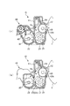
次に、図6〜図8を参照して、現像装置の一例についてより具体的に説明する。 Next, an example of the developing device will be described more specifically with reference to FIGS.
本例にて、現像装置10は、ハウジング、即ち、現像容器11を備えている。現像容器11は、像担持体としての感光体ドラム1と対向する開口部12に位置して現像剤担持体としての現像スリーブ13を回転自在に配置している。
In this example, the developing
現像容器11は、現像スリーブ13に対して近くに配置された現像室15と、遠くに配置された攪拌室16とを備えており、現像室15と攪拌室16とは仕切壁17にて仕切られている。
The developing
現像室15に形成された第1搬送路21には、現像スリーブ13の軸線とほぼ平行に前側撹拌軸、即ち、第1現像剤搬送部材31が配置されている。そして攪拌室16に形成された第2搬送路22には、現像スリーブ13の軸線とほぼ平行に後側撹拌軸、即ち、第2現像剤搬送部材32が配置されている。第1及び第2現像剤搬送部材31、32の2本の現像剤搬送部材31、32は、それぞれ、現像室15及び攪拌室16にて、つまり、第1及び第2搬送路21、22にて現像剤を撹拌しながら循環搬送する。
In the
図7にて、現像室15と攪拌室16とを仕切る、即ち、第1搬送路21と第2搬送路22との間には仕切壁17が形成されている。仕切り壁の両端17a、17aには、これら両端17a、17aにそれぞれ対向するハウジング10の両側壁18、19との間に、それぞれ第1開口部23と第2開口部24が形成されている。
In FIG. 7, the developing
第1開口部23は、第1搬送路21から第2搬送路22へ現像剤を受け渡す役目をし、第2開口部24は、第2搬送路22から第1搬送路21へ現像剤を受け渡す役目をしている。
The
従って、仕切壁17は、第1搬送路21及び第2搬送路22の両端17a、17a部分のみが第1開口部23と第2開口部24により互いに連通するように形成されている。そして、第1搬送路21及び第2搬送路22の他の部分は互いに遮断された現像剤の循環経路を形成している。現像剤は、図7にて矢印方向に撹拌されながら循環される。
Therefore, the
図7の現像装置において、第1現像剤搬送部材31は、多条の、本例では3条のスクリュー部を有しており、第2現像剤搬送部材32は、1条のスクリュー部を有している。また、第1現像剤搬送部材31及び第2現像剤搬送部材32は、上述のように、現像剤を互いに逆方向に搬送するように、第1搬送路21及び第2搬送路22にそれぞれ配置されている。
In the developing apparatus of FIG. 7, the first
しかしながら、従来の上記現像装置10において、仕切壁17が、多条スクリュー部を有する第1現像剤搬送部材31の現像剤搬送方向下流側に長く延在し、即ち、第1開口部23の空間が狭い場合には、以下の問題が生じる。すなわち、この開口部分で現像剤の循環バランスが崩れ、現像剤の滞留及び現像スリーブ13からの現像剤の溢れを引き起こす懸念があった。
However, in the conventional developing
また、開口部23に対応する側壁18を、特許文献2に記載するように、円弧状にすると平面の時よりは効果があるものの搬送方向のベクトルが一定ではない。そのために、第1現像剤搬送部材の31の軸端部に設けられた現像剤戻し回転羽根31cによる現像剤返しとのバランスがとれないこととなる。そのために、開口部23における現像剤の循環バランスがとれずに、画像濃度や現像剤の凝集度によっては現像剤の滞留が解消しきれないことがある。また、現像容器11が大きくなり、省スペース化が進む昨今においては現実的ではない。
Further, as described in Patent Document 2, if the
上記問題は、第2現像剤搬送部材32に、多条スクリュー部を設けた場合には第2開口部24について言えることである。
The above problem is true for the second opening 24 when the second
そこで本発明の目的は、現像剤搬送部材に多条スクリュー部を設けた場合であっても、現像剤の滞留を防止し、画像不良のない高品質な現像装置を提供することである。 It is an object of the present invention, even when providing the multi-start screw portion in the developer conveying member, to prevent stagnation of the developer is to provide an image failure without a high-quality development apparatus.
上記目的は本発明に係る現像装置にて達成される。要約すれば、本発明は、現像剤を担持搬送し、像担持体上に形成された静電像を現像する現像剤担持体と、
前記現像剤担持体に対向配置されて前記現像剤担持体に現像剤を供給する第1搬送路と、
前記第1搬送路内の現像剤を搬送する第1現像剤搬送部材と、
前記第1搬送路に沿って設けられた第2搬送路と、
前記第2搬送路内の現像剤を搬送する第2現像剤搬送部材と、
前記第1搬送路と前記第2搬送路との間に配設された隔壁と、
前記隔壁の両端部にそれぞれ形成され、前記第1搬送路から前記第2搬送路へと現像剤の受け渡しをする第1開口部と、
前記第2搬送路から前記第1搬送路へと現像剤の受け渡しをする第2開口部と、
を備えた現像装置において、
前記第1現像剤搬送部材及び前記第2現像剤搬送部材の少なくとも一方の現像剤搬送部材は、多条の螺旋状回転羽根が形成された多条スクリュー部を有し、
前記多条スクリュー部の条数をn、前記多条スクリュー部の軸線方向の各回転羽根のピッチをPとしたとき、前記第1開口部及び前記第2開口部のうち、前記多条スクリュー部が設けられた搬送路の少なくとも現像剤搬送方向下流部の開口部は、前記多条スクリュー部のうち、搬送路内の現像剤搬送方向に向かって搬送させる搬送部の搬送方向下流端部から上流側へと、前記多条スクリュー部の軸線方向にnP以上の長さにわたって開口されていることを特徴とする現像装置である。
The above object is achieved by the developing device according to the present invention. In summary, the present invention provides a developer carrying body for carrying and transporting a developer and developing an electrostatic image formed on the image carrying body,
A first conveying path that is disposed opposite to the developer carrier and supplies the developer to the developer carrier;
A first developer transport member that transports the developer in the first transport path;
A second transport path provided along the first transport path;
A second developer conveying member for conveying the developer in the second conveying path;
A partition wall disposed between the first transport path and the second transport path;
A first opening formed on each end of the partition wall for transferring developer from the first transport path to the second transport path;
A second opening for transferring developer from the second transport path to the first transport path;
In a developing device comprising:
At least one developer conveying member of the first developer conveying member and the second developer conveying member has a multi-threaded screw portion in which a multi-spiral rotating blade is formed,
The Article number n of the multi-start screw portion, wherein when a pitch of the rotating blades in the axial direction of the multi-start screw portions is P, one of the first opening and the second opening, the multi-start screw portion at least the developer opening of the conveying direction downstream of the conveying path provided is of the multi-start screw portion, upstream from the downstream end in the conveyance direction of the conveying section for conveying toward the developer conveying direction of the conveying path To the side, the developing device is characterized by being opened over a length of nP or more in the axial direction of the multi-thread screw portion .
本発明によれば、現像剤搬送部材に多条スクリュー部を設けた場合であっても、現像剤の滞留を防止し、画像不良のない高品質な現像装置を提供することができる。 According to the present invention, even when a multi-thread screw portion is provided on the developer conveying member , it is possible to provide a high-quality developing device that prevents the developer from staying and has no image defects.
以下、本発明に係る現像装置を図面に則して更に詳しく説明する。 Hereinafter, the developing device according to the present invention will be described in more detail with reference to the drawings.
実施例1
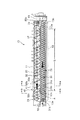
図1(a)、(b)に、本発明に係る現像装置の一実施例の概略構成を示す。
Example 1
1A and 1B show a schematic configuration of an embodiment of a developing device according to the present invention.
尚、現像装置の構成部品の寸法、材質、形状、及びその相対位置等は、特に特定的な記載がない限りは、この発明の範囲をそれらのみに限定する趣旨のものではない。 Note that the dimensions, materials, shapes, relative positions, and the like of the components of the developing device are not intended to limit the scope of the present invention only to those unless otherwise specified.
本実施例の現像装置は、その全体構成は、図6を参照して説明した従来の現像装置と同様の構成とされる。 The overall configuration of the developing device of this embodiment is the same as that of the conventional developing device described with reference to FIG.
つまり、図1(a)、(b)〜図3を参照すると、現像装置10は、ハウジング、即ち、現像容器11を備えている。現像容器11は、像担持体としてのドラム状の電子写真感光体、即ち、感光体ドラム1と対向する位置に開口部12が形成されている。この開口部12に、感光体ドラム1と対向して現像剤担持体としての現像スリーブ13が回転自在に担持されている。現像スリーブ13の内部には、磁界発生手段としてのマグネットローラ13aが配置されている。本実施例では、現像容器11内には、磁性キャリアとトナーを有する2成分現像剤が収納されている。
That is, with reference to FIGS. 1A and 1B to 3, the developing
また、現像容器11の、前記開口部12の上縁部に近接して、現像スリーブ13に担持搬送される現像剤の量を規制するための現像剤層厚規制部材、即ち、ドクターブレード14が配置されている。
Further, a developer layer thickness regulating member for regulating the amount of developer carried and conveyed by the developing
現像容器11内には、現像スリーブ13に対して近くに配置された現像室15と、現像室15に隣接し、現像スリーブ13からは遠くに配置された攪拌室16とを備えており、現像室15と攪拌室16とは仕切壁、即ち、隔壁17にて仕切られている。本実施例によると、現像装置10には、補給用現像剤を供給する現像剤補給装置の現像剤供給ローラ40が配置され、攪拌室16に連通して、補給口41が形成されている。
The developing
現像室15に形成された第1搬送路21には、現像スリーブ13の軸線とほぼ平行に第1の現像剤搬送部材31が配置されている。また、攪拌室16に形成された第2搬送路22には、現像スリーブ13の軸線とほぼ平行に第2の現像剤搬送部材32が配置されている。
A first
第1及び第2現像剤搬送部材31、32は、それぞれ、現像室15及び攪拌室16にて矢印方向(時計方向)に回転し、現像剤を撹拌しながら第1搬送路21及び第2搬送路22にて現像剤の循環搬送を行う。
The first and second
現像室15と攪拌室16とを仕切る隔壁17、即ち、第1搬送路21と第2搬送路22との間に形成された隔壁17の両端17a、17aに位置して、それぞれ第1開口部23及び第2開口部24が形成されている。つまり、第1開口部23及び第2開口部24は、隔壁17の両端17a、17aと、この隔壁の両端17a、17aにそれぞれ対向する現像容器11の両側壁18、19との間に設けられる。
A
第1開口部23は、第1搬送路21から第2搬送路22へ現像剤を受け渡す役目をし、第2開口部24は、第2搬送路22から第1搬送路21へ現像剤を受け渡す役目をしている。
The
従って、隔壁17は、第1搬送路21及び第2搬送路22の両端部分のみを第1開口部23及び第2開口部24により互いに連通するように形成されている。この構成により、第1搬送路21及び第2搬送路22は、現像容器11内における現像剤の循環経路を形成している。従って、現像剤は、図2に示すように、現像容器11内にて第1搬送路21及び第2搬送路22を撹拌されながら矢印方向に循環される。
Accordingly, the
つまり、図2に示すように、第1現像剤搬送部材31及び第2現像剤搬送部材32は、第1搬送路21及び第2搬送路22にて現像剤を互いに逆方向に搬送するように構成されている。
That is, as shown in FIG. 2, the first
次に、第1現像剤搬送部材31及び第2現像剤搬送部材32について説明する。
Next, the first
本実施例にて、第1現像剤搬送部材31及び第2現像剤搬送部材32は、それぞれ、回転軸31a、32aに、螺旋状に回転羽根31b、32bが一体に取り付けられたスクリュー部を有している。また、第1現像剤搬送部材31及び第2現像剤搬送部材32のうちの少なくとも一方は、多条の螺旋状回転羽根が形成された多条のスクリュー部を有している。本実施例では、第1搬送路21に配置された第1現像剤搬送部材31が多条の、本実施例では、3条のスクリュー部を有しており、第2搬送路22に配置された第2現像剤搬送部材32は1条のスクリュー部を有している。
In the present embodiment, the first
又、本実施例では、図2に示すように、第1現像剤搬送部材31の第1開口部23側の端部、即ち、現像剤搬送方向下流端には、螺旋状回転羽根31bのねじり方向とは逆とされた螺旋状の現像剤戻し回転羽根31cが形成されている。同様に、第2現像剤搬送部材32の第2開口部24側の端部、即ち、現像剤搬送方向下流端には、螺旋状回転羽根32bのねじり方向とは逆とされた螺旋状の現像剤戻し回転羽根32cが形成されている。これら現像剤戻し回転羽根31c、32cは、それぞれ、第1及び第2現像剤搬送部材31、32の回転羽根31b、32bにより搬送されてきた現像剤を、それぞれ、第1、第2搬送路21、22から円滑に第1及び第2開口部23、24へと流入させるためのものである。現像剤戻し回転羽根31c、32cは、場合によっては設けなくともよい。
Further, in this embodiment, as shown in FIG. 2, the twist of the spiral
又、本実施例では、第2現像剤搬送部材32には、現像剤が第2搬送路22を搬送される過程において、現像剤の攪拌を効率よく行うために、回転軸32aから半径方向に延在して回転軸の軸線に沿って攪拌片32dが設けられている。各攪拌片32dは、回転方向に異なる位相にて配置することができる。本実施例では、互いに90度づつ位相を異ならせて設けられている。
Further, in this embodiment, the second
次に、現像剤の搬送循環の流れについて説明する。 Next, the flow of developer conveyance and circulation will be described.
上述のように、第1搬送路21内の現像剤は、第1現像剤搬送部材31により矢印方向に撹拌しながら循環され、第1搬送路21の現像剤搬送方向下流側に設けられた第1開口部23から、隣接する第2搬送路22へと受け渡される。
As described above, the developer in the
本実施例にて、図3に拡大して示すように、第1現像剤搬送部材31が多条スクリュー部を有している。このとき、多条スクリュー部の条数をn、軸線方向の各回転羽根のピッチをPとする。
In the present embodiment, as shown in an enlarged view in FIG. 3, the first
本実施例では、多条スクリュー部が設けられた第1現像剤搬送部材31を有する第1搬送路21の現像剤搬送方向下流部の第1開口部23は、以下のように形成される。すなわち、第1開口部23は、多条スクリュー部の現像剤搬送方向下流側端部31dから、多条スクリュー部の現像剤搬送方向上流側へと、多条スクリュー部の軸線方向にnP以上の長さ(S)にわたって開口される。
In the present embodiment, the
本実施例では、第1現像剤搬送部材31の多条スクリュー部は、3条の多条スクリュー部とされるので、第1開口部23は、長さ3P以上に渡って形成されている。又、本実施例では、上述のように、第1現像剤搬送部材31は、端部に現像剤戻し回転羽根31cが形成されている。従って、第1開口部23は、図3にて、隔壁17の長手方向端部17aから、多条スクリュー部の終端(即ち、現像剤戻し回転羽根31cが始まる位置)31dまでの距離S以上に開口されている。
In this embodiment, multi-start screw portion of the first
このように、本実施例では、上記距離(S)が長さ(nP)以上とされるが、従来においては、図8にて理解されるように、上記距離(S)は、高々、1ピッチ(P)とされているに過ぎない。 As described above, in the present embodiment, the distance (S) is equal to or longer than the length (nP). Conventionally, as understood in FIG. 8, the distance (S) is at most 1 It is only a pitch (P).
上述のように、本実施例によると、第1現像剤搬送部材31から第2現像剤搬送部材32への現像剤の受け渡し部、即ち、第1開口部23は、多条スクリュー部の現像剤搬送方向下流側端部31dから、多条スクリュー部の現像剤搬送方向上流側へと、多条スクリュー部の軸線方向にnP以上の長さ(S)にわたって開口される。従って、現像剤の円滑な受け渡しを行うことができる。
As described above, according to this embodiment, the developer delivery portion from the first
しかしながら、本発明者らの研究実験の結果によれば、2nPを超える空間を設けた(即ち、S>2nP)場合には、現像剤の循環バランスが崩れ、側壁18の近傍に現像剤が滞留し、端部濃度薄などの画像不良の原因となってしまう、ことが分かった。
However, according to the results of the research experiments by the present inventors, when a space exceeding 2 nP is provided (that is, S> 2 nP), the developer circulation balance is lost and the developer stays in the vicinity of the
また、本実施例のように、第1開口部23の近傍に補給口41が設けられているような構成では、第1開口部23を、Sが2nPを超えるように開口した場合には、現像剤受け渡し部が補給口41にまで達することとなる。このような構成では、補給口41からの補給用現像剤は、第2搬送路22内を矢印方向へと撹拌循環されて第1搬送路21へと循環され、その後現像スリーブ13へと送給されることがない。補給口41からの補給用現像剤は、少なくとも一部が直ちに第1搬送路21へと移動し、現像スリーブ13に供給されてしまい、カブリや濃度ムラの原因となる。
Further, in the configuration in which the replenishing
従って、第1開口部23は、距離Sが(nP)以上、(2nP)以下(即ち、nP≦S≦2nP)となるように開口されることが好ましい。
Therefore, the
図2に図示されるように、本実施例によれば、現像スリーブ13における現像剤担持領域の長手軸線方向両端部13a、13bが、それぞれ、第1開口部23及び第2開口部24の位置に位置しているのが好ましい。また、このとき、感光体ドラム1上に形成された静電像を現像する現像スリーブ13による現像領域(L)の両端位置は、それぞれ、隔壁17の両端部よりも、長手方向における内側に位置しているのが好ましい。これは、現像に寄与する領域(L)において、隣接した部屋との現像剤の移動が生じると、現像剤担持ムラや、現像剤摩擦帯電ムラを生じ、画像不良を生じる可能性がある為である。なお、この場合の(L)は、装置が形成しうる最大サイズの静電像が形成された場合の、これに対向する現像スリーブの領域である。
As shown in FIG. 2, according to the present embodiment, the
以上の構成とされる本実施例の現像装置によれば、画像面上に濃度不足やムラが発生することを防止することができ、更には、現像スリーブ13からの現像剤の溢れやスクリューロックのない良質な画像を得ることができる。
According to the developing apparatus of the present embodiment having the above-described configuration, it is possible to prevent insufficient density and unevenness on the image surface, and further, overflow of developer from the developing
上記実施例では、第1現像剤搬送部材31が多条スクリュー部を有する場合の、第1開口部23について説明した。しかし、第2現像剤搬送材32が多条スクリュー部を有する場合には、第2開口部24についても、同様の構成とすることにより、同様の作用効果を達成し得る。
In the above embodiment, the
又、上記本発明の原理は、第1現像剤搬送部材31及び第2現像剤搬送部材32の双方共に多条スクリュー部を有する場合についても同様に適用し、同様の作用効果を達成し得る。
The principle of the present invention is also applied to the case where both the first
また、本実施例の現像装置で用いた現像剤及び現像装置の構成等はこれらに限ったものではなく、本発明が様々な現像剤及び現像装置の構成に適用可能であることは言うまでもない。更に具体的には、開口部の開口広さや、現像剤搬送部材のスクリュー部の条数等は本実施例に限定されるものではない。 Further, the developer and the configuration of the developing device used in the developing device of this embodiment are not limited to these, and it goes without saying that the present invention can be applied to various configurations of the developer and the developing device. More specifically, the opening width of the opening and the number of threads of the developer conveying member are not limited to the present embodiment.
実施例2
図4及び図5を参照して本発明の現像装置の第二の実施例を説明する。
Example 2
A second embodiment of the developing apparatus of the present invention will be described with reference to FIGS.
本実施例においても、現像装置の全体構成及び機能は、実施例1で説明したものと同様に構成することができる。従って、本実施例の現像装置において同じ構成及び機能を成す部材には同じ参照番号を付し、現像装置の全体構成及び機能についての説明は、実施例1を援用し、ここでの再度の説明は省略する。 Also in this embodiment, the overall configuration and function of the developing device can be configured in the same manner as that described in the first embodiment. Accordingly, the same reference numerals are given to members having the same configuration and function in the developing device of the present embodiment, and the description of the entire configuration and function of the developing device is based on the first embodiment and will be described again here. Is omitted.
本実施例の現像装置は、画像形成装置の出力スピードの増加により画像形成装置のプロセススピードが増速した場合に対応するための「現像剤搬送速度を増大した現像装置」とされる。 The developing device of this embodiment is a “developing device with an increased developer conveyance speed” to cope with an increase in the process speed of the image forming apparatus due to an increase in the output speed of the image forming apparatus.
実施例1と同様の現像装置において、画像形成装置のプロセススピードが増速した場合には、現像剤搬送能力を維持するために、プロセススピードをアップした分、現像剤搬送部材の回転数をアップさせなければならない。そのために、本実施例においては、プロセススピードをアップした結果、前記第1現像剤搬送部材31及び第2現像剤搬送部材32の回転数もスピードアップすることとなる。
In the same developing apparatus as in Example 1, when the process speed of the image forming apparatus is increased, the rotation speed of the developer conveying member is increased by an amount corresponding to the increased process speed in order to maintain the developer conveying ability. I have to let it. Therefore, in this embodiment, as a result of increasing the process speed, the rotational speeds of the first
このとき、上記実施例1の構成では、現像剤の受け渡し部である第1開口部23における現像剤の循環が、円滑に循環できないことがあった。
At this time, in the configuration of Example 1, the developer may not be smoothly circulated in the
そこで、本実施例においては、図4及び図5に示すように、隔壁17の第1搬送路21における現像剤搬送方向最下流側端部の、第1搬送路21側の領域S0をテーパ状にする。即ち、隔壁17の第1搬送路21の現像剤搬送方向最下流側端部領域S0が第1開口部23の方へと次第に拡大されることとなり、この構成により、第1搬送路21から第1開口部23へと至る現像剤の搬送をスムーズにすることができる。つまり、隔壁17は、その長手方向の断面が異なる形状とされる。
Therefore, in this embodiment, as shown in FIGS. 4 and 5, the region S <b> 0 on the
このように、第1現像剤搬送部材31の多条スクリュー部が設けられた第1搬送路21の水平方向の幅が、現像剤搬送方向下流側の端部において広がるように、隔壁17は中央部に比べて端部の厚さが薄い形状とされる。
Thus, the
具体的には、本実施例においては、第1搬送路21側のテーパ状領域S0は、少なくとも、第1現像剤搬送部材31の最小ピッチ(P)の長さ、隔壁17の断面を変更する。このとき、本実施例では、隔壁17の現像剤搬送方向最下流側端部17aの最小厚さt0は、隔壁17の厚さ(t)に対して(1/2)tとした。
Specifically, in the present embodiment, the tapered region S0 on the
しかし、これに限定されるものではなく、好ましくは、現像剤搬送方向最下流端17aからの隔壁17の断面の変更領域S0の長さを、最大、(nP)〜(3nP)、即ち、P≦S0≦(nP〜3nP)とする。そして、最小厚さt0を(1/5)tから(4/5)t、即ち、(1/5)t≦t0≦(4/5)tとすることができる。
However, the present invention is not limited to this, and preferably, the length of the change area S0 of the cross section of the
これにより、プロセススピードがアップし、第1現像剤搬送部材31と第2現像剤搬送部材32の回転数がアップしても画像面上に濃度不足やムラが発生することを防止することができる。更には、現像スリーブ13からの現像剤の溢れやスクリューロックのない良質な画像を得ることができる。
As a result, the process speed is increased, and even when the rotation speed of the first
また、本実施例の現像装置で用いた現像剤及び現像装置の構成等はこれらに限ったものではなく、本発明が様々な現像剤及び現像装置の構成に適用可能であることは言うまでもない。具体的には、隔壁17の断面の構成がテーパ形状ではなく、階段状であっても、円弧状であったとしても問題はない。また、現像剤搬送部材である螺旋状回転羽根の条数等は本実施例に限定されるものではない。
Further, the developer and the configuration of the developing device used in the developing device of this embodiment are not limited to these, and it goes without saying that the present invention can be applied to various configurations of the developer and the developing device. Specifically, there is no problem even if the configuration of the cross section of the
上記実施例では、第1現像剤搬送部材31が多条スクリュー部を有する場合の、第1開口部23側の隔壁17の端部について説明した。しかし、第2現像剤搬送材32が多条スクリュー部を有する場合には、第2開口部24側の隔壁17の端部についても、同様の構成とすることにより、同様の作用効果を達成し得る。
In the above embodiment, the end portion of the
又、上記本発明の原理は、第1現像剤搬送部材31及び第2現像剤搬送部材32の双方共に多条スクリュー部を有する場合についても同様に適用し、同様の作用効果を達成し得る。
The principle of the present invention is also applied to the case where both the first
また、本実施例の現像装置で用いた現像剤及び現像装置の構成等はこれらに限ったものではなく、本発明が様々な現像剤及び現像装置の構成に適用可能であることは言うまでもない。更に具体的には、開口部の開口広さや、現像剤搬送部材のスクリュー部の条数等は本実施例に限定されるものではない。 Further, the developer and the configuration of the developing device used in the developing device of this embodiment are not limited to these, and it goes without saying that the present invention can be applied to various configurations of the developer and the developing device. More specifically, the opening width of the opening and the number of threads of the developer conveying member are not limited to the present embodiment.
1 感光体ドラム(像担持体)
10 現像装置
11 現像容器
13 現像スリーブ(現像剤担持体)
15 現像室
16 攪拌室
17 仕切壁(隔壁)
21 第1搬送路
22 第2搬送路
23、24 開口部
31 第1現像剤搬送部材
32 第2現像剤搬送部材
41 補給口
1 Photosensitive drum (image carrier)
DESCRIPTION OF
15 Developing
21
Claims (6)
前記現像剤担持体に対向配置されて前記現像剤担持体に現像剤を供給する第1搬送路と、
前記第1搬送路内の現像剤を搬送する第1現像剤搬送部材と、
前記第1搬送路に沿って設けられた第2搬送路と、
前記第2搬送路内の現像剤を搬送する第2現像剤搬送部材と、
前記第1搬送路と前記第2搬送路との間に配設された隔壁と、
前記隔壁の両端部にそれぞれ形成され、前記第1搬送路から前記第2搬送路へと現像剤の受け渡しをする第1開口部と、
前記第2搬送路から前記第1搬送路へと現像剤の受け渡しをする第2開口部と、
を備えた現像装置において、
前記第1現像剤搬送部材及び前記第2現像剤搬送部材の少なくとも一方の現像剤搬送部材は、多条の螺旋状回転羽根が形成された多条スクリュー部を有し、
前記多条スクリュー部の条数をn、前記多条スクリュー部の軸線方向の各回転羽根のピッチをPとしたとき、前記第1開口部及び前記第2開口部のうち、前記多条スクリュー部が設けられた搬送路の少なくとも現像剤搬送方向下流部の開口部は、前記多条スクリュー部のうち、搬送路内の現像剤搬送方向に向かって搬送させる搬送部の搬送方向下流端部から上流側へと、前記多条スクリュー部の軸線方向にnP以上の長さにわたって開口されていることを特徴とする現像装置。 A developer carrying member that carries and conveys the developer and develops the electrostatic image formed on the image carrying member;
A first conveying path that is disposed opposite to the developer carrier and supplies the developer to the developer carrier;
A first developer transport member that transports the developer in the first transport path;
A second transport path provided along the first transport path;
A second developer conveying member for conveying the developer in the second conveying path;
A partition wall disposed between the first transport path and the second transport path;
A first opening formed on each end of the partition wall for transferring developer from the first transport path to the second transport path;
A second opening for transferring developer from the second transport path to the first transport path;
In a developing device comprising:
At least one developer conveying member of the first developer conveying member and the second developer conveying member has a multi-threaded screw portion in which a multi-spiral rotating blade is formed,
The Article number n of the multi-start screw portion, wherein when a pitch of the rotating blades in the axial direction of the multi-start screw portions is P, one of the first opening and the second opening, the multi-start screw portion at least the developer opening of the conveying direction downstream of the conveying path provided is of the multi-start screw portion, upstream from the downstream end in the conveyance direction of the conveying section for conveying toward the developer conveying direction of the conveying path The developing device is opened to the side over the length of nP or more in the axial direction of the multi-thread screw portion .
Priority Applications (3)
| Application Number | Priority Date | Filing Date | Title |
|---|---|---|---|
| JP2006096151A JP4795071B2 (en) | 2006-03-30 | 2006-03-30 | Development device |
| US11/691,113 US7881638B2 (en) | 2006-03-30 | 2007-03-26 | Developing apparatus |
| CNB2007100914807A CN100501594C (en) | 2006-03-30 | 2007-03-30 | Developing apparatus |
Applications Claiming Priority (1)
| Application Number | Priority Date | Filing Date | Title |
|---|---|---|---|
| JP2006096151A JP4795071B2 (en) | 2006-03-30 | 2006-03-30 | Development device |
Publications (3)
| Publication Number | Publication Date |
|---|---|
| JP2007271830A JP2007271830A (en) | 2007-10-18 |
| JP2007271830A5 JP2007271830A5 (en) | 2011-02-24 |
| JP4795071B2 true JP4795071B2 (en) | 2011-10-19 |
Family
ID=38559125
Family Applications (1)
| Application Number | Title | Priority Date | Filing Date |
|---|---|---|---|
| JP2006096151A Active JP4795071B2 (en) | 2006-03-30 | 2006-03-30 | Development device |
Country Status (3)
| Country | Link |
|---|---|
| US (1) | US7881638B2 (en) |
| JP (1) | JP4795071B2 (en) |
| CN (1) | CN100501594C (en) |
Families Citing this family (24)
| Publication number | Priority date | Publication date | Assignee | Title |
|---|---|---|---|---|
| JP4861152B2 (en) * | 2006-12-13 | 2012-01-25 | 株式会社リコー | Developing device, process cartridge, and image forming apparatus |
| JP2009162853A (en) * | 2007-12-28 | 2009-07-23 | Ricoh Co Ltd | Powder transport screw, development device, process unit and image forming apparatus |
| JP4600546B2 (en) | 2008-08-26 | 2010-12-15 | 富士ゼロックス株式会社 | Image forming apparatus |
| JP4569694B2 (en) * | 2008-09-18 | 2010-10-27 | コニカミノルタビジネステクノロジーズ株式会社 | Developer transport device, developing device, and image forming apparatus |
| JP4770951B2 (en) * | 2009-03-12 | 2011-09-14 | 富士ゼロックス株式会社 | Developing device and image forming apparatus |
| JP5463756B2 (en) * | 2009-06-24 | 2014-04-09 | コニカミノルタ株式会社 | Developing device and image forming apparatus |
| JP4878636B2 (en) * | 2009-08-26 | 2012-02-15 | キヤノン株式会社 | Image forming apparatus |
| JP4951694B2 (en) * | 2010-05-20 | 2012-06-13 | シャープ株式会社 | Developing device and image forming apparatus having the same |
| JP4998602B2 (en) * | 2010-06-21 | 2012-08-15 | コニカミノルタビジネステクノロジーズ株式会社 | Developing device and image forming apparatus |
| JP5825912B2 (en) | 2010-10-20 | 2015-12-02 | キヤノン株式会社 | Development device |
| JP2012155251A (en) | 2011-01-28 | 2012-08-16 | Canon Inc | Developing device and image forming apparatus |
| JP2013020062A (en) | 2011-07-11 | 2013-01-31 | Canon Inc | Development apparatus |
| JP5822066B2 (en) * | 2011-07-27 | 2015-11-24 | 株式会社リコー | Developer container, developing device, process unit, and image forming apparatus |
| CN102314131A (en) * | 2011-08-05 | 2012-01-11 | 珠海天威飞马打印耗材有限公司 | Powder chamber of carbon powder box |
| JP2013050526A (en) | 2011-08-30 | 2013-03-14 | Canon Inc | Development apparatus |
| JP2014026045A (en) * | 2012-07-25 | 2014-02-06 | Ricoh Co Ltd | Image forming apparatus and powder transporting member |
| JP2014170197A (en) | 2013-03-05 | 2014-09-18 | Canon Inc | Image forming apparatus |
| JP6308812B2 (en) * | 2014-03-04 | 2018-04-11 | キヤノン株式会社 | Development device |
| JP6551357B2 (en) * | 2016-10-06 | 2019-07-31 | 京セラドキュメントソリューションズ株式会社 | Developing device and image forming apparatus |
| JP6724856B2 (en) * | 2017-05-08 | 2020-07-15 | 京セラドキュメントソリューションズ株式会社 | Developing device and image forming apparatus including the same |
| JP6604992B2 (en) * | 2017-05-22 | 2019-11-13 | キヤノン株式会社 | Developing device and image forming apparatus |
| JP7146493B2 (en) | 2017-07-10 | 2022-10-04 | キヤノン株式会社 | image forming device |
| JP7146508B2 (en) * | 2018-07-31 | 2022-10-04 | キヤノン株式会社 | developing device |
| JP7465434B2 (en) * | 2019-09-25 | 2024-04-11 | 株式会社リコー | Developing device and image forming apparatus |
Family Cites Families (22)
| Publication number | Priority date | Publication date | Assignee | Title |
|---|---|---|---|---|
| US5819132A (en) * | 1995-06-29 | 1998-10-06 | Canon Kabushiki Kaisha | Image forming apparatus capable of toner replenishment based on density of reference toner image and toner replenishment based on ratio of toner to carrier |
| JPH09197782A (en) | 1996-01-12 | 1997-07-31 | Ricoh Co Ltd | Developing device |
| JP3379678B2 (en) | 1996-03-18 | 2003-02-24 | 株式会社リコー | Two-component developing device |
| US5963766A (en) * | 1997-06-09 | 1999-10-05 | Minolta Co., Ltd. | Developing device |
| US6442355B2 (en) * | 1999-02-24 | 2002-08-27 | Canon Kabushiki Kaisha | Developer density controlling apparatus including target density information detection and toner image density detection |
| JP2002139901A (en) * | 2000-10-31 | 2002-05-17 | Ricoh Co Ltd | Developing device and image forming device |
| JP3985472B2 (en) * | 2001-07-12 | 2007-10-03 | 富士ゼロックス株式会社 | Developer transport device |
| JP2003122124A (en) * | 2001-08-07 | 2003-04-25 | Ricoh Co Ltd | Developing device and image forming device |
| JP2003255694A (en) * | 2002-02-28 | 2003-09-10 | Canon Inc | Developing device and image forming apparatus |
| US6973281B2 (en) * | 2002-04-26 | 2005-12-06 | Canon Kabushiki Kaisha | Developing apparatus with two developing chamber-rotatable member pairs |
| US7054583B2 (en) * | 2002-10-07 | 2006-05-30 | Canon Kabushiki Kaisha | Developing device including two developer carrying members |
| US6993274B2 (en) * | 2002-11-14 | 2006-01-31 | Canon Kabushiki Kaisha | Developing apparatus with plural developer bearing members for each image bearing member |
| JP2005049541A (en) * | 2003-07-31 | 2005-02-24 | Ricoh Co Ltd | Toner carrier, developing device and image forming apparatus |
| JP4593950B2 (en) * | 2004-03-23 | 2010-12-08 | キヤノン株式会社 | Image forming apparatus |
| JP2005352225A (en) * | 2004-06-11 | 2005-12-22 | Matsushita Electric Ind Co Ltd | Developing device |
| JP4663289B2 (en) * | 2004-10-19 | 2011-04-06 | キヤノン株式会社 | Image forming apparatus |
| JP2006119304A (en) * | 2004-10-20 | 2006-05-11 | Canon Inc | Image forming apparatus |
| JP4669260B2 (en) * | 2004-10-20 | 2011-04-13 | キヤノン株式会社 | Developer and image forming apparatus |
| JP4630694B2 (en) * | 2005-03-07 | 2011-02-09 | キヤノン株式会社 | Image forming method |
| JP4642529B2 (en) * | 2005-03-31 | 2011-03-02 | キヤノン株式会社 | Development device |
| JP4789553B2 (en) * | 2005-09-08 | 2011-10-12 | キヤノン株式会社 | Developing device and image forming apparatus |
| JP4786284B2 (en) * | 2005-10-07 | 2011-10-05 | 株式会社リコー | Developing device, process unit, and image forming apparatus |
-
2006
- 2006-03-30 JP JP2006096151A patent/JP4795071B2/en active Active
-
2007
- 2007-03-26 US US11/691,113 patent/US7881638B2/en active Active
- 2007-03-30 CN CNB2007100914807A patent/CN100501594C/en not_active Expired - Fee Related
Also Published As
| Publication number | Publication date |
|---|---|
| JP2007271830A (en) | 2007-10-18 |
| US7881638B2 (en) | 2011-02-01 |
| US20070231014A1 (en) | 2007-10-04 |
| CN101046660A (en) | 2007-10-03 |
| CN100501594C (en) | 2009-06-17 |
Similar Documents
| Publication | Publication Date | Title |
|---|---|---|
| JP4795071B2 (en) | Development device | |
| JP6207258B2 (en) | Development device | |
| JP4861152B2 (en) | Developing device, process cartridge, and image forming apparatus | |
| JP5430214B2 (en) | Development device | |
| JP5388652B2 (en) | Development device | |
| JP5393765B2 (en) | Developing device and image forming apparatus including the same | |
| JP2001249545A (en) | Image forming device | |
| JP2009109741A (en) | Developing device and image forming device equipped with it | |
| JP2000347488A (en) | Developing device and process cartridge and image forming device provided with the developing device | |
| JP6344272B2 (en) | Developing device and image forming apparatus including the same | |
| JP6204286B2 (en) | Developing device and image forming apparatus including the same | |
| JP2011191505A (en) | Developing device and image forming apparatus including the same | |
| JP2000137383A (en) | Developing device | |
| JPH08220887A (en) | Developing device | |
| JP2004233597A (en) | Developing device | |
| JP2005215483A (en) | Developing device | |
| JP5793970B2 (en) | Development device | |
| JP2009109966A (en) | Developer transport device, developing device and image forming apparatus | |
| WO2022254915A1 (en) | Developing device and image forming apparatus provided therewith | |
| JP2018116245A (en) | Development device | |
| JP2018072530A (en) | Conveyance member and development apparatus having the same | |
| JP2017032846A (en) | Conveyance member, developing device, and image forming apparatus | |
| JPH09197782A (en) | Developing device | |
| JP4614691B2 (en) | Developing device in image forming apparatus | |
| JP5594906B2 (en) | Stirring member, developing device including the same, and image forming apparatus |
Legal Events
| Date | Code | Title | Description |
|---|---|---|---|
| A621 | Written request for application examination |
Free format text: JAPANESE INTERMEDIATE CODE: A621 Effective date: 20090311 |
|
| A521 | Written amendment |
Free format text: JAPANESE INTERMEDIATE CODE: A523 Effective date: 20110111 |
|
| A871 | Explanation of circumstances concerning accelerated examination |
Free format text: JAPANESE INTERMEDIATE CODE: A871 Effective date: 20110111 |
|
| A975 | Report on accelerated examination |
Free format text: JAPANESE INTERMEDIATE CODE: A971005 Effective date: 20110201 |
|
| A131 | Notification of reasons for refusal |
Free format text: JAPANESE INTERMEDIATE CODE: A131 Effective date: 20110222 |
|
| A521 | Written amendment |
Free format text: JAPANESE INTERMEDIATE CODE: A523 Effective date: 20110421 |
|
| TRDD | Decision of grant or rejection written | ||
| A01 | Written decision to grant a patent or to grant a registration (utility model) |
Free format text: JAPANESE INTERMEDIATE CODE: A01 Effective date: 20110719 |
|
| A01 | Written decision to grant a patent or to grant a registration (utility model) |
Free format text: JAPANESE INTERMEDIATE CODE: A01 |
|
| A61 | First payment of annual fees (during grant procedure) |
Free format text: JAPANESE INTERMEDIATE CODE: A61 Effective date: 20110727 |
|
| R151 | Written notification of patent or utility model registration |
Ref document number: 4795071 Country of ref document: JP Free format text: JAPANESE INTERMEDIATE CODE: R151 |
|
| FPAY | Renewal fee payment (event date is renewal date of database) |
Free format text: PAYMENT UNTIL: 20140805 Year of fee payment: 3 |