JP4129593B2 - Image forming apparatus - Google Patents
Image forming apparatus Download PDFInfo
- Publication number
- JP4129593B2 JP4129593B2 JP2002197680A JP2002197680A JP4129593B2 JP 4129593 B2 JP4129593 B2 JP 4129593B2 JP 2002197680 A JP2002197680 A JP 2002197680A JP 2002197680 A JP2002197680 A JP 2002197680A JP 4129593 B2 JP4129593 B2 JP 4129593B2
- Authority
- JP
- Japan
- Prior art keywords
- developer
- image
- image forming
- toner
- forming apparatus
- Prior art date
- Legal status (The legal status is an assumption and is not a legal conclusion. Google has not performed a legal analysis and makes no representation as to the accuracy of the status listed.)
- Expired - Fee Related
Links
Images

Description
【0001】
【発明の属する技術分野】
本発明は、画像形成装置に関する。
【0002】
【従来の技術】
画像形成装置としては、例えばトナーとキャリアとよりなる2成分現像剤(以下、単に「現像剤」ともいう。)を担持して搬送することによって潜像担持体に対して現像剤を供給する回転スリーブよりなる現像剤担持体と、現像剤を混合、撹拌しながら搬送しつつ当該現像剤担持体に対して供給する現像剤撹拌供給手段とを備えてなる現像部を有するものが広く用いられている。
【0003】
このような画像形成装置の或る種の現像部においては、現像剤撹拌供給手段が現像剤を搬送する現像剤搬送路が形成されており、この現像剤搬送路において現像剤を搬送するために、現像剤撹拌供給手段を構成する、例えばスクリューよりなる現像剤搬送部材を、現像剤担持体と共通の駆動手段によって常に駆動させている。そして、現像剤搬送部材によって現像剤搬送路上を搬送されている現像剤を、例えば現像剤撹拌供給手段を構成する現像剤撹拌供給部材を介して現像剤担持体の配置されている領域と連続し、当該現像剤担持体の回転軸の伸びる方向に沿って伸びる領域(以下、「現像剤供給領域」ともいう。)において、当該現像剤担持体に対して供給する構成を有している。
【0004】
しかしながら、特に印字率の大きい可視画像を形成する場合には、一の画像形成処理中において、現像剤搬送路の現像剤供給領域における上流部で多量のトナーが消費されてしまう結果、現像担持体に対して、当該上流部に対応する部分にのみ多量のトナーが供給され、その一方で、現像剤供給領域の下流部に対応する部分に供給することのできるトナー量が必然的に小さくなるため、最終的に転写材に形成される可視画像に、当該転写材の一端から他端に向かうに従って画像濃度が次第に小さくなる濃度むら(以下、「画像濃度むら」ともいう。)が発生し、高い画質を有する可視画像を得ることができない、という問題がある。
【0005】
このような問題について検討を重ねた結果、例えば現像剤搬送部材の回転数を大きくするなどして2成分現像剤の搬送速度を大きくし、一の画像形成処理中において現像剤搬送路上の現像剤搬送量を大きくすることによって画像濃度むらを抑制することができるが、搬送速度を大きくすることに伴って、現像剤が現像剤搬送部材の回転などによる搬送作用によって受けるストレスが大きくなり、その結果、現像剤が劣化することに起因して得られる可視画像においてかぶりなどが発生することとなり、結局、長期間にわたる可視画像形成動作中において、得られる可視画像の画質が次第に悪化する原因となる、ということが判明した。
【0006】
【発明が解決しようとする課題】
本発明は以上のような事情に基づいてなされたものであって、その目的は、長期間にわたって、高い画質の可視画像が得られる画像形成装置を提供することにある。
本発明の他の目的は、複数のトナー像形成装置を備えてなり、長期間にわたって、高い画質の可視画像が得られ、しかも小型の画像形成装置を提供することにある。
【0007】
【課題を解決するための手段】
本発明の画像形成装置は、潜像担持体の表面に静電荷像を露光処理によって形成する像露光部と、トナーとキャリアとよりなる2成分現像剤を担持して現像領域に搬送するよう回転する現像剤担持体、および2成分現像剤を混合撹拌しながら搬送しつつ前記現像剤担持体に対して供給する現像剤撹拌供給手段を有し、潜像担持体に形成された静電荷像を現像する現像部と、現像部により現像されたトナー像を転写部材に転写する転写部とを有する画像形成装置であって、前記現像剤撹拌供給手段は前記現像剤担持体と独立した駆動手段を有すると共に、下記(1)の構成を有することを特徴とする。
【0008】
(1)潜像担持体の表面における転写部材に転写されるべきトナー像が形成される画像形成用領域以外のパッチ画像形成用領域に形成されたパッチ画像の濃度を前記現像剤撹拌供給手段の現像剤搬送方向における2箇所において各々検出し、検出されたパッチ画像濃度の差異を検知するパッチ画像濃度差異検知手段が設けられており、
パッチ画像濃度差異検知手段によって検知されるパッチ画像濃度の差異に応じて、現像剤撹拌供給手段を構成する現像剤搬送部材による2成分現像剤の搬送速度を制御する現像剤搬送速度制御手段を有する構成
【0009】
本発明の画像形成装置においては、少なくとも現像剤攪拌供給手段および現像剤担持体を有するトナー像形成ユニットが構成され、当該トナー像形成ユニットを複数備えることが好ましい。
以上のような本発明の画像形成装置においては、現像部の現像剤撹拌供給手段を構成する現像剤搬送部材と、当該現像部に対してトナーを補給するトナー補給機構とが共通の駆動手段によって駆動される構成を有するものであってもよい。
【0010】
また、本発明の画像形成装置においては、前記複数のトナー像形成ユニットのうち少なくとも2つのトナー像形成ユニットに係る現像剤撹拌供給手段を構成する現像剤搬送部材が共通の駆動手段によって駆動されることが好ましい。
【0016】
本発明の画像形成装置においては、潜像担持体の表面に形成されたトナー像を第1の転写部材である転写ベルトに転写する一次転写部と、当該一次転写部において転写ベルトに転写されたトナー像を第2の転写部材である転写材に転写する二次転写部とを有し、
パッチ画像濃度差異検知手段が、転写ベルトの表面においてパッチ画像濃度を検出する構成を有することが好ましい。
【0017】
本発明の画像形成装置においては、現像剤撹拌供給手段を構成する現像剤搬送部材が回転部材であって、現像剤搬送速度制御手段による現像剤の搬送速度の制御が現像剤搬送部材の回転速度を加減することによって行われる。
【0018】
【作用】
本発明の画像形成装置によれば、可視画像を形成するために必要とされるトナー量を検知するための特定の検知手段と、当該特定の検知手段によって検知される特定の情報に応じて現像剤搬送路上における2成分現像剤の搬送速度を制御する特定の現像剤搬送速度制御手段が設けられており、可視画像を形成するために必要とされるトナー量が大きい場合に限って、2成分現像剤の搬送速度を大きくすることができるため、一の画像形成処理中に現像剤搬送路上から消費されるトナー量が大きくても、現像剤搬送路上の現像剤搬送量を大きくすることによって現像剤担持体に対してその回転軸の伸びる方向において比較的均一に2成分現像剤を供給することができることから、得られる可視画像における画像濃度むらの発生を抑制することができると共に、現像剤撹拌供給手段による2成分現像剤の搬送に起因する劣化を十分に抑制することができる。
従って、本発明の画像形成装置によれば、長期間にわたって、高い画質を有する可視画像を得ることができる。
【0019】
また、画像形成装置が複数のトナー像形成ユニットを備えてなる場合には、当該複数のトナー像形成ユニットの各々に、特定の検知手段および特定の現像剤搬送速度制御手段が設けられており、また、特定の現像剤搬送速度制御手段によって制御される制御対象の現像剤搬送部材と、現像剤担持体とを駆動する駆動手段各々が独立して設けられているが、当該制御対象の現像剤搬送部材が共通駆動手段によって駆動する構成を有するため、当該画像形成装置の構成部材数を低減することができ、これにより、特定の検知手段および特定の現像剤搬送速度制御手段を設けることに伴う画像形成装置自体の大型化を防止することができる。
従って、本発明の画像形成装置によれば、複数のトナー像形成装置を備えてなり、長期間にわたって、高い画質の可視画像が得られ、しかも装置自体の小型化を図ることができる。
【0020】
【発明の実施の形態】
以下、本発明について図面を用いて詳細に説明する。
【0021】
〔第1の実施の形態〕
<実施の形態(1A)>
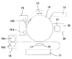
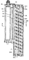
図1は、本発明の画像形成装置の構成の一例の概略を示す説明図であり、図2は、図1の画像形成装置の現像部の構成を示す説明用横断平面図であり、図3は、図2にかかる現像部のAA断面を示す説明用縦断平面図である。
この画像形成装置は、図1において時計方向(矢印方向)に回転する、例えば有機感光体よりなる潜像担持体10と、この潜像担持体10を、例えばグリッドとコロナ放電ワイヤによるコロナ放電によって一様に帯電するための帯電部12と、一様に帯電した潜像担持体10に対して画像読取部(図示せず)の原稿画像情報に基づいて、例えばレーザーダイオード(図示せず)から放射されたレーザー光によって露光処理を行うことにより、その表面に静電荷像を形成する像露光部13と、潜像担持体10の表面に形成された静電荷像を現像してトナー像を形成する現像部20と、潜像担持体10に形成されたトナー像を、例えば紙などの転写材よりなる転写部材に転写させる転写部16と、潜像担持体10に密着した転写材を分離させる分離部17と、転写材の表面に転写されたトナー像を定着させる一対の加熱ローラ18aおよび加圧ローラ18bを有する定着部18とを備えてなる。同図において、11は転写材供給部、19はクリーニング部である。クリーニング部19は、電気的にクリーニングを行うクリーニングローラ19aと、機械的にクリーニングを行うブレード19bとにより構成されている。
【0022】
現像部20は、図2および図3に示すように、潜像担持体10を臨む側面に開口28Cを有し、トナーおよびキャリアよりなる現像剤(2成分現像剤)が導入されたハウジング28内において、現像剤を担持して潜像担持体10に対して供給する回転スリーブ22よりなる現像剤担持体21と、当該現像剤担持体21を駆動する駆動手段(図示せず)と、現像剤担持体21の表面に形成される現像剤層の厚さを規制する現像剤規制部材23と共に、現像剤を混合、撹拌しながら搬送しつつ現像剤担持体21に対して供給するための現像剤撹拌供給手段24を備えている。
この例においては、ハウジング28の天面板28Aにおける現像剤撹拌供給手段24を構成する後述する第1の現像剤搬送部材26の羽根部材26A上の位置(図2において(イ)で示す位置)に、ハウジング28内にトナー補給機構(図示せず)からトナー(以下、「新トナー」ともいう。)を補給するためのトナー補給用開口(図示せず)が形成されている。
【0023】
現像剤撹拌供給手段24は、図3において反時計方向(矢印方向)に回転する、十字パドル形状であって現像剤担持体21の回転軸の伸びる方向に伸びる回転部材よりなり、現像剤を撹拌しつつ現像剤担持体21に対して供給する現像剤撹拌供給部材(以下、「撹拌供給パドル」ともいう。)25と、一端側(図2において下端側)に板状の羽根部材26Aを有する螺旋状の回転部材よりなり、撹拌供給パドル25に平行に配置され、当該撹拌供給パドル25が現像剤担持体21に供給すべき現像剤を当該現像剤担持体21の回転軸の伸びる方向(図2において下方)に搬送する第1の現像剤搬送部材(以下、「第1の搬送スクリュー」ともいう。)26と、他端側(図2において上端側)に板状の羽根部材27Aを有する螺旋状の回転部材よりなり、ハウジング28の底面板28Bから突出する隔壁29を隔てて当該第1の搬送スクリュー26に平行に配置され、トナー補給機構からトナー補給用開口を介して補給される新トナーをハウジング28内の現像剤と混合しつつ搬送する第2の現像剤搬送部材(以下、「第2の搬送スクリュー」ともいう。)27と、撹拌供給パドル25、第1の搬送スクリュー26および第2の搬送スクリュー27の各々を回転させる、現像剤担持体21の駆動手段とは独立した専用の駆動手段(図示せず)とにより構成されている。
【0024】
この例においては、トナー補給用開口から補給された新トナーは、先ず、隔壁29の第1の連絡開口29Cを介して、図3において時計方向(矢印方向)に回転する第2の搬送スクリュー27に係る現像剤搬送路(以下、「第2の搬送路」ともいう。)29Bを通り抜け、次いで当該隔壁29の第2の連絡開口29Dを介して、図3において反時計方向(矢印方向)に回転する第1の搬送スクリュー26に係る現像剤搬送路(以下、「第1の搬送路」ともいう。)29A上を搬送される過程において混合される。
そして、第1の搬送路29Aを搬送されている現像剤は、撹拌供給パドル25を介して現像剤担持体21が配置されている領域と連続する現像剤供給領域において、当該現像剤担持体21に対して供給される。また、第1の搬送路29Aおよび第2の搬送路29Bよりなる現像剤搬送路が循環型のものであることから、第1の搬送路29A上を搬送される過程において画像形成処理に用いられなかった現像剤は、第1の搬送スクリュー26によって第2の搬送路29Bに向かって搬送され、当該第2の搬送路29B上を搬送された後、再び第1の搬送路29A上を搬送されることとなる。
【0025】
そして、この画像形成装置には、例えば入力された画像情報に各種の画像処理を施して像露光部13において静電荷像を形成するための画像データを生成する画像データ生成手段によって生成された画像データを検知する画像データ検知手段(以下、「第1の画像データ検知手段」ともいう。)が設けられており、更に、第1の画像データ検知手段によって検知される画像データに応じて現像剤撹拌供給手段24を構成する第1の搬送スクリュー26および第2の搬送スクリュー27による現像剤の搬送速度を制御する現像剤搬送速度制御手段(以下、「第1の現像剤搬送速度制御手段」ともいう。)が設けられている。
【0026】
第1の画像データ検知手段としては、画像データ生成手段によって生成された画像データが2値画像である場合は、像露光部13において潜像担持体10の表面に静電荷像を形成する際の画素比率を検知するものが用いられる。
ここに、「画素比率」とは、生成された画像データに基づいて潜像担持体10の表面に対して画像毎に、像露光部13によって像露光をON/OFFして静電荷像を形成する際に、形成すべき静電荷像における像露光をONとする画素の比率である。
【0027】
第1の現像剤搬送速度制御手段は、第1の画像データ検知手段によって検知される画像データに応じて第1の搬送スクリュー26および第2の搬送スクリュー27の回転数を加減することによって現像剤搬送速度制御を行うものであり、具体的には、第1の画像データ検知手段によって検知される画素比率が大きくなるに従って第1の搬送スクリュー26および第2の搬送スクリュー27の回転数を大きくするよう制御を行う。
ここに、第1の現像剤搬送速度制御手段は、現像剤搬送路上における現像剤の搬送安定性を得るために第1の搬送スクリュー26および第2の搬送スクリュー27の両方による現像剤搬送速度を制御する構成を有するものであることが好ましい。
この例においては、第1の現像剤搬送速度制御手段により、第1の搬送スクリュー26および第2の搬送スクリュー27(以下、「制御対象搬送スクリュー」ともいう。)に対して共通の制御が行われる。
【0028】
具体的に、第1の現像剤搬送速度制御手段としては、例えば制御対象搬送スクリューを駆動する駆動モータ(駆動手段)の回転数を制御することにより現像剤の搬送速度を制御する装置を用いることができる。
この第1の現像剤搬送速度制御手段による現像剤の搬送速度制御の好ましい形態としては、例えば第1の画像データ検知手段によって検知される画素比率(画像データ)が50%未満である場合には、制御対象搬送スクリューの回転数(現像剤搬送速度)を100〜300rpmとし、画素比率が50%以上である場合には、制御対象搬送スクリューの回転数を350〜500rpmとする。
【0029】
以上のような画像形成装置の作動は次のとおりである。
画像読取部によって原稿の画像が読み込まれて原稿画像情報が得られ、画像データ生成手段によってこの原稿画像情報に各種の画像処理が施されて静電荷像形成のための画像データが生成され、この画像データに基づいて、像露光部13において露光処理を行うことにより、潜像担持体10の表面に静電荷像が形成される。一方、転写材供給部11から転写材が送り出され、潜像担持体10と同期した状態で転写部16に向けて搬送される。
【0030】
そして、現像部20においては、ハウジング28内にてトナーとキャリアとが第1の搬送スクリュー26および第2の搬送スクリュー27によって混合され、現像剤として第1の搬送路29A上を搬送される過程において、撹拌供給パドル25によって撹拌されつつ現像剤担持体21の表面に対して供給されて現像剤担持体21の表面に付着されて現像剤層を形成し、この現像剤層は、現像剤規制部材23によってその厚みが規制されて必要な現像剤量に制限された後、図3に示す現像領域Pまで搬送され、この現像領域Pにおいて、現像剤層が潜像担持体10の表面に磁気ブラシを形成して接触され、これにより、当該潜像担持体10の表面に形成された静電荷像に従ってトナーが付着して現像が行われ、トナー像が得られる。
また、一の画像形成処理が終了すると、当該画像形成処理において撹拌供給パドル25によって現像剤担持体21に供給されずに第1の搬送路29A上に残留している現像剤および撹拌供給パドル25によって供給されたものの、例えば現像剤規制部材23の作用などによって第1の搬送路29A上に戻された現像剤が、第1の搬送スクリュー26によって第2搬送路29Bに向かって搬送される。
【0031】
このようにして潜像担持体10の表面に形成されたトナー像は、転写部16において、搬送された転写材に転写される。そして、潜像担持体10に密着した状態にある転写材は、トナー像の転写直後に、分離部17において潜像担持体10から分離される。その後、潜像担持体10から分離された転写材は、定着部18に向かって搬送され、当該定着部18においてトナー像が熱定着され、転写材に原稿の画像に対応した可視画像が形成され、この可視画像が形成された転写材は、定着部18から排出された後、搬送されて外部に排出される。
また、転写材が分離された後の潜像担持体10は、クリーニング部19を通過することにより、表面に残留しているトナーが除去される。
【0032】
以上のような画像形成作動中の現像部20においては、常に、現像剤撹拌供給手段24を構成する撹拌供給パドル25、第1の搬送スクリュー26および第2の搬送スクリュー27の各々が対応する専用の駆動手段によって回転されているが、第1の画像データ検知手段により検知される画素比率が一定のレベル以上となると、第1の現像剤搬送速度制御手段によって第1の搬送スクリュー26および第2の搬送スクリュー27の回転数が大きくされる。
【0033】
このように、潜像担持体10に形成された静電荷像の画像比率が大きく、可視画像を形成するために必要とされるトナー量が大きい場合には、第1の搬送スクリュー26および第2の搬送スクリュー27の回転数が大きくなって現像剤搬送路上の現像剤搬送量が大きくなるため、一の画像形成処理中に第1の搬送路29A上において消費されるトナー量が大きくても、現像剤担持体21に対して、第1の搬送路29Aにおける現像剤供給領域の上流部に対応する部分にのみ多量のトナーが供給されることなく、その回転軸の伸びる方向において比較的均一に現像剤を供給することができるため、最終的に転写材に形成される可視画像において、転写材の一端から他端に向かうに従って画像濃度が次第に小さくなる画像濃度むらの発生を抑制することができる。
また、可視画像を形成するために必要とされるトナー量が大きい場合に限って第1の搬送スクリュー26および第2の搬送スクリュー27の回転数が大きくされることにより、第1の搬送スクリュー26および第2の搬送スクリュー27による現像剤の搬送に起因する劣化を十分に抑制することができ、しかも、可視画像を形成するために必要とされるトナー量が小さい場合には、第1の搬送路29A上において消費されるトナー量が小さいことから、第1の搬送スクリュー26および第2の搬送スクリュー27の回転数が大きくなくても、得られる可視画像に、実用上問題のある画像濃度むらが発生するという弊害を伴うことがない。 従って、実施の形態(1A)の画像形成装置によれば、長期間にわたって、高い画質の可視画像を得ることができる。
【0034】
このような実施の形態(1A)においては、種々の変更を加えることができる。
例えば画像データ生成手段によって生成された画像データが多値画像である場合は、第1の画像データ検知手段が、像露光部において潜像担持体の表面に形成される静電荷像を構成する画素に係る露光量の積算値(以下、「積算露光量」ともいう。)を検知するものであると共に、第1の現像剤搬送速度制御手段が検知される積算露光量に応じて第1の現像剤撹拌供給手段を構成する第1の搬送スクリューおよび第2の搬送スクリューによる現像剤の搬送速度を制御するものであってもよい。
【0035】
ここに、「露光量の積算値」とは、例えば形成すべき画像を構成する各画素が256階調で表現される場合には、画素毎に設定された0〜255の露光量を所定の面積当たりに積算した値である。
【0036】
積算露光量に応じて制御を行う第1の現像剤搬送速度制御手段としては、例えば制御対象搬送スクリューを駆動する駆動モータ(駆動手段)の回転数を制御することにより現像剤の搬送速度を制御する装置を用いることができ、この第1の現像剤搬送速度制御手段による現像剤搬送速度制御の好ましい形態としては、例えば第1の画像データ検知手段によって検知される積算露光量(画像データ)が最大値の50%未満である場合には、制御対象搬送スクリューの回転数(現像剤搬送速度)を100〜300rpmとし、積算露光量が最大値の50%以上である場合には、制御対象搬送スクリューの回転数を350〜500rpmとする。
【0037】
また、画像形成装置は、現像部に新トナーを供給するためのトナー補給機構と、現像剤撹拌供給手段を構成する第1の搬送スクリューとが、共通の駆動手段によって駆動される構成のものであってもよい。この場合には、トナー補給機構と、第1の搬送スクリューとの各々に、専用の駆動手段を個別に設ける必要がないことから、画像形成装置を構成する構成部材数を低減することができ、当該画像形成装置を小型化することが可能となる。
【0038】
また、画像形成装置は、クリーニング部により除去されたトナー(リサイクルトナー)を現像部に搬送するリサイクル手段が備えられており、このリサイクル手段によって当該クリーニング部により除去されたリサイクルトナーの一部あるいは全部が現像部に搬送されて再利用される構成のものであってもよい。
【0039】
<実施の形態(1B)>
実施の形態(1B)の画像形成装置は、第1の画像データ検知手段の代わりに、現像剤撹拌供給手段が現像剤を搬送する現像剤搬送路上の現像剤におけるトナー濃度変化割合を検知するトナー濃度変化割合検知手段(以下、「第1のトナー濃度変化割合検知手段」ともいう。)が設けられており、この第1のトナー濃度変化割合検知手段によって検知されるトナー濃度変化割合に応じて、現像剤撹拌供給手段を構成する現像剤搬送部材(第1の搬送スクリューおよび第2の搬送スクリュー)による現像剤の搬送速度を制御する現像剤搬送速度制御手段(以下、「第2の現像剤搬送速度制御手段」ともいう。)が設けられていること以外は、実施の形態(1A)と同様の構成を有する。
【0040】
第1のトナー濃度変化割合検知手段としては、例えば第1の搬送路29A内における第1の連結開口29Cの近傍であってハウジング28の底面板28B上の位置に設けられており、現像部20に係る現像剤搬送路上の現像剤における実測トナー濃度の、予め定めた基準トナー濃度からの変化割合(以下「対基準変化割合」ともいう。)をトナー濃度変化割合として検知するものが用いられる。
具体的に、第1のトナー濃度検知手段としては、例えば磁性体からなるキャリアとトナーとからなる現像剤の透磁率を検知する透磁率検知方式によりトナー濃度を検出するトナー濃度センサによって実測トナー濃度を測定し、この測定値に基づいて、予め記録されている基準トナー濃度からの変化割合を検知する構成を有する装置などを用いることができる。
【0041】
第2の現像剤搬送速度制御手段は、第1のトナー濃度変化割合検知手段によって検知されるトナー濃度変化割合に応じて第1の搬送スクリュー26および第2の搬送スクリュー27(制御対象搬送スクリュー)の回転数を加減することによって現像剤搬送速度制御を行うものであり、具体的には、第1のトナー濃度変化割合検知手段によって検知される対基準変化割合が大きくなるに従って第1の搬送スクリュー26および第2の搬送スクリュー27の回転数を大きくするよう制御を行う。
ここに、第2の現像剤搬送速度制御手段は、第1の搬送スクリュー26および第2の搬送スクリュー27の両方による現像剤の搬送速度を制御する構成のものであることが好ましい。
【0042】
第2の現像剤搬送速度制御手段としては、例えば制御対象搬送スクリューを駆動する駆動モータ(駆動手段)の回転数を制御することにより現像剤の搬送速度を制御する装置を用いることができ、この第2の現像剤搬送速度制御手段による現像剤の搬送速度制御の好ましい形態としては、例えば第1のトナー濃度変化割合検知手段によって検知される対基準変化割合(トナー濃度変化割合)が0.3質量%未満である場合には、制御対象搬送スクリューの回転数(現像剤搬送速度)を100〜300rpmとし、対基準変化割合が0.3質量%以上で0.6質量%未満である場合には、制御対象搬送スクリューの回転数を350〜400rpmとし、対基準変化割合が0.6質量%以上ある場合には、制御対象搬送スクリューの回転数を450〜500rpmとする。
【0043】
このような画像形成装置によれば、実施の形態(1A)の画像形成装置と同様にして、長期間にわたって、高い画質を有する可視画像を得ることができるという作用効果が得られるが、実施の形態(1B)の画像形成装置は、可視画像を形成するために実際に用いられたトナー消費量の大きさに基づいて現像剤の搬送速度を制御する構成を有する。
【0044】
このような実施の形態(1B)の画像形成装置においては、種々の変更を加えることができる。
例えば第1のトナー濃度変化割合が、現像部に係る現像剤搬送路上の現像剤における単位時間当たりの変化割合(以下、「単位変化割合」ともいう。)をトナー濃度変化割合として検知するものであると共に、第2の現像剤搬送速度制御手段が、検知される単位変化割合に応じて現像剤撹拌供給手段を構成する第1の搬送スクリューおよび第2の搬送スクリューによる現像剤の搬送速度を制御するものであってもよい。
このような構成の第1のトナー濃度変化割合検知手段としては、具体的に、例えば透磁率検知方式によりトナー濃度を検出するトナー濃度センサによって定期的にトナー濃度を測定し、得られた複数の測定値に基づいて、単位時間当たりの変化割合(単位変化割合)を検知する構成を有する装置などを用いることができる。
【0045】
単位変化割合に応じて制御を行う第2の現像剤搬送速度制御手段としては、例えば制御対象搬送スクリューを駆動する駆動モータ(駆動手段)の回転数を制御することにより現像剤の搬送速度を制御する装置を用いることができ、この第2の現像剤搬送速度制御手段による現像剤搬送速度制御の好ましい形態としては、例えば第1のトナー濃度変化割合検知手段によって検知される単位変化割合が0.3質量%未満である場合には、制御対象搬送スクリューの回転数を100〜300rpmとし、単位変化割合が0.3質量%以上で0.6質量%未満である場合には、制御対象搬送スクリューの回転数を350〜400rpmとし、単位変化割合が0.6質量%以上である場合には、制御対象搬送スクリューの回転数を450〜500rpmとする。
【0046】
また、実施の形態(1A)に係る画像形成装置と同様にして、実施の形態(1B)に係る画像形成装置は、トナー補給機構と第1の搬送スクリューとを駆動する共通駆動手段を有するもの、あるいはリサイクル手段を有するものであってもよい。
【0047】
<実施の形態(1C)>
実施の形態(1C)の画像形成装置は、第1の画像データ検知手段の代わりに、潜像担持体の表面における転写部材に転写されるべきトナー像が形成される画像形成用領域以外のパッチ画像形成用領域に形成されたパッチ画像の濃度を現像剤搬送方向における2箇所において各々検出し、検出されたパッチ画像濃度の差異を検知するパッチ画像濃度差異検知手段(以下、「第1のパッチ画像濃度差異検知手段」ともいう。)が設けられており、この第1のパッチ画像濃度差異検知手段によって検知されるパッチ画像濃度差異に応じて、現像剤撹拌供給手段を構成する現像剤搬送部材(第1の搬送スクリューおよび第2の搬送スクリュー)による現像剤の搬送速度を制御する現像剤搬送速度制御手段(以下、「第3の現像剤搬送速度制御手段」ともいう。)が設けられていること以外は、実施の形態(1A)と同様の構成を有する。
【0048】
第1のパッチ画像濃度差異検知手段としては、潜像担持体10の表面のパッチ画像形成用領域において、現像剤搬送方向に離間して形成された2個のパッチ画像の濃度の差異(以下、「2個パッチ濃度差異」ともいう。)をパッチ画像濃度差異として検知するものが用いられる。
具体的に、第1のパッチ画像濃度差異検知手段としては、例えば潜像担持体10の回転方向における現像部20とクリーニング部19との間の領域における当該潜像担持体の回転軸の伸びる方向の一端部および他端部であって、現像剤搬送方向に離間した2箇所(以下、「パッチ画像形成箇所」ともいう。)に各々設けられた、例えば光学的反射濃度センサなどのセンサにより、パッチ画像形成箇所の各々に形成されたパッチ画像のパッチ画像濃度を測定し、これらの測定値に基づいて、2個パッチ濃度差異を検知する構成を有する装置などを用いることができる。
なお、この画像形成装置においては、最高濃度制御(Dmax制御)機構および階調補正制御機構が設けられており、これらの制御機構が第1のパッチ画像濃度差異検知手段を構成するセンサによって測定されるパッチ画像濃度に基づいて最高濃度制御(Dmax制御)および階調補正制御を行う構成を有している。
【0049】
第3の現像剤搬送速度制御手段は、第1のパッチ画像濃度差異検知手段によって検知されるパッチ画像濃度差異に応じて第1の搬送スクリュー26および第2の搬送スクリュー27(制御対象搬送スクリュー)の回転数を加減することによって現像剤搬送速度制御を行うものであり、具体的には、第1のパッチ画像濃度差異検知手段によって検知される2個パッチ濃度差異が大きくなるに従って第1の搬送スクリュー26および第2の搬送スクリュー27の回転数を大きくするよう制御を行う。
ここに、第3の現像剤搬送速度制御手段は、第1の搬送スクリュー26および第2の搬送スクリュー27の両方による現像剤の搬送速度を制御する構成のものであることが好ましい。
【0050】
第3の現像剤搬送速度制御手段としては、例えば制御対象搬送スクリューを駆動する駆動モータ(駆動手段)の回転数を制御することにより現像剤の搬送速度を制御する装置を用いることができ、この第3の現像剤搬送速度制御手段による現像剤搬送速度制御の好ましい形態としては、例えば第1のパッチ画像濃度差異検知手段によって検知される2個パッチ濃度差異(パッチ画像濃度差異)が0.2未満である場合には、制御対象搬送スクリューの回転数(現像剤搬送速度)を100〜300rpmとし、2個パッチ濃度差異が0.2以上である場合には、制御対象搬送スクリューの回転数を350〜500rpmとする。
【0051】
このような画像形成装置によれば、実施の形態(1A)の画像形成装置と同様にして、長期間にわたって、高い画質を有する可視画像を得ることができるという作用効果が得られるが、実施の形態(1C)の画像形成装置は、現状の現像剤の搬送速度条件によって生じる画像濃度むらの程度を予め測定し、その測定値に基づいて現像剤の搬送速度を制御する構成を有する。
【0052】
このような実施の形態(1C)の画像形成装置においては、種々の変更を加えることができる。
例えば第1のパッチ画像濃度差異検知手段は、潜像担持体の表面のパッチ画像形成用領域に形成された、例えばその一端および他端が、各々、潜像担持体の回転軸の伸びる方向における一端部と他端部とに至る大きさを有する1個のパッチ画像の現像剤搬送方向に離間した2箇所の濃度の差異をパッチ画像濃度差異として検知するものであってもよい。
【0053】
第1のパッチ画像濃度差異検知手段を構成するパッチ画像濃度を測定するセンサは、ジャム検知用のセンサとして併用することができる。
また、画像形成装置は、潜像担持体の表面に形成されたトナー像を第1の転写部材である転写ベルトに転写する一次転写部と、当該一次転写部において転写ベルトに転写されたトナー像を第2の転写部材である転写材に転写する二次転写部とを有し、パッチ画像濃度差異検知手段が、潜像担持体の表面のパッチ画像形成用領域において、当該潜像担持体の回転軸の伸びる方向であって、現像剤搬送方向に離間して形成された2個のパッチ画像の各々のパッチ画像濃度を、一次転写部において転写された転写ベルトの表面においてパッチ画像濃度を検出する構成を有するものであってもよい。
【0054】
また、実施の形態(1A)に係る画像形成装置と同様にして、実施の形態(1C)に係る画像形成装置は、トナー補給機構と第1の搬送スクリューとを駆動する共通駆動手段を有するもの、あるいはリサイクル手段を有するものであってもよい。
【0055】
以上において、第1の実施の形態の画像形成装置を、潜像担持体、像露光部、現像部および転写部を各々1個有するモノクロ画像形成用の画像形成装置において説明したが、当該画像形成装置は、複数のトナー像形成ユニットを備えてなるカラー画像形成用の画像形成装置として好適に用いられる。
【0056】
〔第2の実施の形態〕
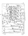
図4は、本発明の画像形成装置の構成の一例を示す説明図である。
この画像形成装置は、原稿を光学的に走査して原稿画像を読み込んで原稿画像情報を形成する画像読取部31と、当該画像読取部31よりの原稿画像情報に基づいて、各々表面にトナー像が形成される潜像担持体51Y、51M、51C、51Kを有する4個のトナー像形成ユニット41Y、41M、41C、41Kおよび各トナー像形成ユニット41Y、41M、41C、41Kで形成されたトナー像を一次転写して担持するための第1の転写部材であるエンドレスベルトよりなる中間転写ベルト42を有するトナー像形成装置40と、当該中間転写ベルト42の表面に形成された一次転写トナー像を、例えば紙などの転写材よりなる第2の転写部材の表面に転写する二次転写部32と、転写材の表面に転写された二次転写トナー像を定着させるための加熱ローラ33aおよび加圧ローラ33bを有する定着部33と、転写材を搬送する搬送機構と、画像形成が完了した転写材を排出する排出口35とを備えてなる。
同図において、37は中間転写ベルト用クリーニング部であり、38a、38b、38cは転写材カセットである。
【0057】
トナー像形成装置40においては、例えば複数のローラ42a、42b、42c、42dによって移動可能に支持され、図4において矢印方向に循環移動するエンドレスベルトよりなる中間転写ベルト42の下向部分が移動される略直線状の移動路に沿って、当該中間転写ベルト42の回転方向にトナー像形成ユニット41Y、41M、41C、41Kが並列配置されている。
ここで、トナー像形成ユニット41Yにおいては黄色のトナー像が形成され、トナー像形成ユニット41Mにおいてはマゼンタ色のトナー像が形成され、トナー像形成ユニット41Cにおいてはシアン色のトナー像が形成され、トナー像形成ユニット41Kにおいては黒色のトナー像が形成される。
【0058】
トナー像形成装置40は、4個のトナー像形成ユニット41Y、41M、41C、41Kのすべてが作動されることにより、いわゆるフルカラーのカラー画像を形成することができると共に、当該4個のトナー像形成ユニット41Y、41M、41C、41Kのうちの1つに係る潜像担持体51Kを選択的に用いることにより、例えば黒色のトナーのみによりモノクロ画像を形成することができる。
【0059】
以下、トナー像形成装置40を構成する4個のトナー像形成ユニット41Y、41M、41C、41Kのうちのトナー像形成ユニット41Yの構成について説明するが、他のトナー像形成ユニット41M、41C、41Kも、各々、下記のトナー像形成ユニット41Yと同様の構成を有するものとされている。
【0060】
トナー像形成ユニット41Yには、中間転写ベルト42と転写位置において順方向(図4において矢印方向)に移動するよう回転する潜像担持体51Yが備えられていると共に、この潜像担持体51Yの外周面領域には、その回転方向に沿って、当該潜像担持体51Yを、例えばグリッドとコロナ放電ワイヤによるコロナ放電によって一様に帯電するための帯電部52Yと、一様に帯電した潜像担持体51Yに対して画像読取部31の原稿画像情報に基づいて、例えばレーザーダイオード(図示せず)からレーザー光を放射して露光処理を行うことにより、その表面に静電荷像を形成する像露光部53Yと、潜像担持体51Yの表面に形成された静電荷像を現像する現像部54Yと、中間転写ベルト42を介して潜像担持体51Yを圧接する圧接用ローラ56Yを備え、潜像担持体51Yに形成されたトナー像を中間転写ベルト42に一次転写させる一次転写部55Yと、潜像担持体51Yの表面に付着しているトナーの除去を行う潜像担持体用クリーニング部57Yとが備えられている。
【0061】
現像部54Yは、実施の形態(1A)の画像形成装置における現像部20と同様にして、現像剤が導入されており、トナー補給機構からトナー補給用開口を介して新トナーが補給されるハウジング内に、現像剤担持体と、当該現像剤担持体を駆動する駆動手段と、現像剤規制部材と、撹拌供給パドル、第1の搬送スクリューおよび第2の搬送スクリューを備えてなる現像剤撹拌供給手段とにより構成されている(図2および図3参照)。
【0062】
そして、この画像形成装置においては、トナー像形成ユニットの各々に、下記(1)〜(3)のいずれかの構成を有する検知手段(以下、「特定検知手段」ともいう。)と、対応する特定検知手段によって検知される情報に応じて現像剤撹拌供給手段を構成する第1の搬送スクリューおよび第2の搬送スクリュー(制御対象搬送スクリュー)を制御する現像剤搬送速度制御手段(以下、「特定現像剤搬送速度制御手段」ともいう。)とが設けられている。
ここに、特定現像剤搬送速度制御手段は、第1の搬送スクリューおよび第2の搬送スクリューの両方による現像剤の搬送速度を制御する構成のものであることが好ましい。
【0063】
(1)特定検知手段として、トナー像形成装置40を構成する4個のトナー像形成ユニット41Y、41M、41C、41Kの各々の像露光部53Y、53M、53C、53Kにおいて形成される静電荷像の画像データを検知する合計4個の画像データ検知手段(以下、「第2の画像データ検知手段」ともいう。)が設けられており、これらの第2の画像データ検知手段が実施の形態(1A)の画像形成装置における第1の画像データ検知手段と同様の構成を有する。
4個のトナー像形成ユニット41Y、41M、41C、41Kの各々に設けられている合計4個の第2の画像データ検知手段の各々に対応する特定現像剤搬送速度検知手段としては、実施の形態(1A)における第1の現像剤搬送速度制御手段として用いることのできる装置が用いられ、また、第1の現像剤搬送速度制御手段による現像剤搬送速度制御と同様の制御が好ましい形態として挙げられる。
【0064】
(2)特定検知手段として、トナー像形成装置40を構成する4個のトナー像形成ユニット41Y、41M、41C、41Kの各々の現像部54Y、54M、54C、54Kの現像剤撹拌供給手段が現像剤搬送路上の現像剤におけるトナー濃度変化割合を検知する合計4個のトナー濃度変化割合検知手段(以下、「第2のトナー濃度変化割合検知手段」ともいう。)が設けられており、これらの第2のトナー濃度変化割合検知手段が実施の形態(1B)の画像形成装置における第1トナー濃度変化割合検知手段と同様の構成を有する。
4個のトナー像形成ユニット41Y、41M、41C、41Kの各々に設けられている合計4個の第2のトナー濃度変化割合検知手段の各々に対応する特定現像剤搬送速度検知手段としては、実施の形態(1B)における第2の現像剤搬送速度制御手段として用いることのできる装置が用いられ、また、第2の現像剤搬送速度制御手段による現像剤搬送速度制御と同様の制御が好ましい形態として挙げられる。
【0065】
(3)特定検知手段として、トナー像形成装置40を構成する4個のトナー像形成ユニット41Y、41M、41C、41Kの各々の潜像担持体51Y、51M、51C、51Kの表面における転写部材に転写されるべきトナー像が形成される画像形成用領域以外のパッチ画像形成用領域に形成されたパッチ画像の濃度を現像剤搬送方向における2箇所において各々検出し、検出されたパッチ画像濃度の差異を検知するパッチ画像濃度差異検知手段(以下、「第2のパッチ画像濃度差異検知手段」ともいう。)が設けられており、これらの第2のパッチ画像濃度差異検知手段が実施の形態(1C)の画像形成装置における第1のパッチ画像濃度差異検知手段と同様の構成を有する。
【0066】
ここに、第2のパッチ画像濃度差異検知手段は、4個のトナー像形成ユニット41Y、41M、41C、41Kの各々に設けられており、これらの第2のパッチ画像濃度差異検知手段の各々は、対応する潜像担持体51Y、51M、51C、51Kの表面に形成されたパッチ画像に基づいてパッチ画像濃度差異を検知するものである。
【0067】
4個の第2のパッチ画像濃度差異検知手段の各々に対応する特定現像剤搬送速度検知手段としては、実施の形態(1C)における第3の現像剤搬送速度制御手段として用いることのできる装置が用いられ、また、第3の現像剤搬送速度制御手段による現像剤搬送速度制御と同様の制御が好ましい形態として挙げられる。
【0068】
更に、4個のトナー像形成ユニット41Y、41M、41C、41Kの各々に係る現像部54Y、54M、54C、54Kの各々においては、現像剤担持体および撹拌供給パドルと、第1の搬送スクリューおよび第2の搬送スクリューとは、各々、独立した駆動手段によって個別に駆動されるが、第1の搬送スクリュー(第1の現像剤搬送部材)および第2の搬送スクリュー(第2の現像剤搬送部材)は、トナー補給機構と共通の駆動手段(以下、「第1の共通駆動手段」ともいう。)によって駆動される。
【0069】
具体的に、第1の共通駆動手段としては、例えば第1の搬送スクリューおよび第2の搬送スクリューを駆動する駆動系あるいは駆動モータと、トナー補給機構を駆動する駆動系とを電磁クラッチを介して連結してなる装置を用いることができる。
【0070】
以上のような画像形成装置の作動による画像形成プロセスは次のとおりである。
トナー像形成装置40において、すべての潜像担持体51Y、51M、51C、51Kに対して中間転写ベルト42が圧接状態にあってカラー画像を形成する場合には、画像読取部31によって原稿の画像が読み込まれて原稿画像情報が得られ、この原稿画像情報に基づいて、トナー像形成装置40における各々のトナー像形成ユニット41Y、41M、41C、41Kの像露光部53Y、53M、53C、53Kにおいて露光処理を行うことにより、それぞれの潜像担持体51Y、51M、51C、51Kの表面に静電荷像が形成され、この静電荷像の現像が現像部54Y、54M、54C、54Kで行われることにより異なる色のトナー像が得られる。そして、潜像担持体51Y、51M、51C、51Kの表面に形成された各々のトナー像を、一次転写部55Y、55M、55C、55Kにおいてこの順に循環移動する中間転写ベルト42の表面に転写することにより一次転写トナー像が重畳形成される。
ここで、一次転写後の潜像担持体51Y、51M、51C、51Kは、それぞれ潜像担持体用クリーニング部57Y、57M、57C、57Kを通過することにより、表面に残留しているトナーが除去される。
一方、例えば転写材カセット38aから転写材が送り出され、中間転写ベルト42と同期した状態で二次転写部32に向けて搬送される。
【0071】
このようにして中間転写ベルト42の表面に形成された一次転写トナー像は、二次転写部32において搬送された転写材に二次転写される。その後、二次転写トナー像が転写された転写材は、定着部33に向かって搬送され、当該定着部33においてトナー像が熱定着されて転写材に原稿の画像に対応した可視画像が形成される。そして、この可視画像が形成された転写材は、定着部33から排出された後、搬送されて排出口35から外部に排出され、これにより、カラー画像が形成される。
また、転写材が分離された後の中間転写ベルト42は、中間転写ベルト用クリーニング部37を通過することにより、表面に残留しているトナーが除去される。
【0072】
一方、トナー像形成装置40において、潜像担持体51Kのみに対して中間転写ベルト42が圧接状態にあってモノクロ画像を形成する場合には、画像読取部31によって原稿の画像が読み込まれた原稿画像情報に基づいて、トナー像形成装置40におけるトナー像形成ユニット41Kに係る潜像担持体51Kにのみトナー像が形成され、一次転写部55Kにおいて一次転写が行われること以外は上述のカラー画像を形成する場合と同様の画像形成プロセスが行われることにより、モノクロ画像が形成される。
【0073】
以上のような画像形成動作中の現像部54Y、54M、54C、54Kの各々においては、常に、第1の搬送スクリューおよび第2の搬送スクリュー(制御対象搬送スクリュー)が対応する駆動手段によって回転されているが、特定検知手段により検知される特定情報が一定のレベル以上となると、特定現像剤搬送速度制御手段によって第1の搬送スクリューおよび第2の搬送スクリューの回転数が大きくされる。
【0074】
そして、トナー像形成ユニット41Y、41M、41C、41Kの各々においては、特定現像剤搬送速度制御手段によって制御対象搬送スクリューの回転数が大きくされると、それと同期してトナー補給機構からのトナー補給速度が速くなり、現像部54Y、54M、54C、54Kに対して新トナーが多量に補給され、一方、この状態から特定現像剤搬送速度制御手段によって制御対象搬送スクリューの回転数が小さくされると、それと同期してトナー補給機構によるトナー補給速度は遅くなり、新トナーが少量ずつ補給される。このようにして、トナー像形成ユニット41Y、41M、41C、41Kの各々においては、トナー補給機構から現像部54Y、54M、54C、54Kに新トナーが補給される。
なお、トナー補給機構による新トナーの補給量は、例えば現像部54Y、54M、54C、54Kの各々を構成するハウジング内のトナー濃度などに応じて適宜に調節される。
【0075】
以上のような画像形成装置においては、トナー像形成装置40を構成する4個のトナー像形成ユニット41Y、41M、41C、41Kの各々において、可視画像を形成するために必要とされるトナー量が大きい場合には、第1の搬送スクリューおよび第2の搬送スクリューの回転数が大きくなって現像剤搬送路上の現像剤搬送量が大きくなるため、一の画像形成処理中に第1の搬送路上において消費されるトナー量が大きくても、現像剤担持体に対して、第1の搬送路の現像剤供給領域の上流部に対応する部分にのみ多量のトナーが供給されることなく、その回転軸の伸びる方向において比較的均一に現像剤を供給することができるため、最終的に転写材に形成される可視画像において、転写材の一端から他端に向かうに従って画像濃度が次第に小さくなる画像濃度むらの発生を抑制することができる。
また、可視画像を形成するために必要とされるトナー量が大きい場合に限って第1の搬送スクリューおよび第2の搬送スクリューの回転数が大きくされることにより、第1の搬送スクリューおよび第2の搬送スクリューによる現像剤の搬送に起因する劣化を十分に抑制することができ、しかも、可視画像を形成するために必要とされるトナー量が小さい場合には、第1の搬送路上において消費されるトナー量が小さいことから、第1の搬送スクリューおよび第2の搬送スクリューの回転数が大きくなくても、得られる可視画像に、実用上問題のある画像濃度むらが発生するという弊害を伴うことがない。
従って、第2の実施の形態の画像形成装置によれば、長期間にわたって、高い画質の可視画像を得ることができる。
【0076】
また、この画像形成装置においては、4個のトナー像形成ユニット41Y、41M、41C、41Kの各々に、特定検知手段および特定現像剤搬送速度制御手段が備えられているが、トナー補給機構と、第1の搬送スクリューおよび第2の搬送スクリューとが共通駆動手段によって駆動されることから、トナー補給機構と、第1の搬送スクリューおよび第2の搬送スクリューとの各々に、専用の駆動手段を個別に設ける必要がないため、画像形成装置を構成する構成部材数を低減することができ、当該画像形成装置を小型のものとすることができる。
【0077】
このような第2の実施の形態においては、種々の変更を加えることができる。例えば第2の画像形成装置は、当該画像形成装置自体を小型化するためには、4個のトナー像形成ユニットに係る現像部の各々を構成する第1の搬送スクリューおよび第2の搬送スクリューと、当該現像部に係るトナー補給機構とが、各々、共通の駆動手段によって駆動される構成を有するものであることが好ましいが、現像部のうちの少なくとも1つの現像部を構成する第1の搬送スクリューおよび第2の搬送スクリューと、当該現像部に対して新トナーを供給するトナー補給機構とが共通の駆動手段によって駆動されるものであってもよい。
【0078】
また、特定検知手段として、第2のパッチ画像濃度差異検知手段が設けられてなる場合には、当該第2のパッチ画像濃度差異検知手段が、4個のトナー像形成ユニットに共通のものであって、この第2のパッチ画像濃度差異検知手段が、潜像担持体の表面のパッチ画像形成用領域において、当該潜像担持体の回転軸の伸びる方向であって、現像剤搬送方向に離間して形成された2個のパッチ画像の各々のパッチ画像濃度を、一次転写部において転写された転写ベルトの表面においてパッチ画像濃度を検出する構成を有するものであってもよい。この場合には、トナー像形成装置を構成する複数のトナー像形成ユニットごとに第2のパッチ画像濃度差異検知手段を設ける必要がない。
【0079】
また、第2の実施の形態の画像形成装置は、中間転写ベルトに代えてトナー像が転写される転写材を担持するためのエンドレスベルトよりなる転写材搬送ベルトを有するトナー像形成装置を備えたものであってもよい。
【0080】
更に、実施の形態(1A)に係る画像形成装置と同様にして、第2の実施の形態に係る画像形成装置は、リサイクル手段を有するものであってもよい。
【0081】
〔第3の実施の形態〕
第3の実施の形態の画像形成装置は、第1の共通駆動手段の代わりに、トナー像形成装置を構成する4個のトナー像形成ユニットの各々における現像部に係る第1の搬送スクリューおよび第2の搬送スクリューを駆動するための共通の駆動手段(以下、「第2の共通駆動手段」ともいう。)と、当該現像部に係るトナー補給機構の各々を駆動するための駆動手段が設けられていること以外は、第2の実施の形態と同様の構成を有する。
この画像形成装置においては、4個のトナー像形成ユニットの各々に係る第1の搬送スクリューおよび第2の搬送スクリューのすべては第2の共通駆動手段によって駆動されるが、当該4個の現像部の各々に係る現像剤担持体および撹拌パドルは独立した駆動手段によって個別に駆動される。
【0082】
この例においては、例えばトナー像形成装置を構成する4個のトナー像形成ユニットの各々に係る現像部のハウジング内におけるトナー濃度センサにより測定されるハウジング内におけるトナー濃度が過小となると、例えば画像形成装置全体の動作状態を制御する制御部により補給指令信号が発せられ、トナー補給機構用の駆動手段がこの補給指令信号を受けてトナー補給機構から現像部に対して新トナーが補給され、一方、トナー補給機構からの新トナーの補給により、ハウジング内におけるトナー濃度が過大となると、制御部により補給停止信号が発せられ、トナー補給機構による新トナーの補給が停止される。このようにして、トナー補給機構から現像部に新トナーが補給される。
第2の共通駆動手段としては、例えば各トナー像形成ユニットに係る第1の搬送スクリューおよび第2の搬送スクリューを駆動する駆動系あるいは駆動モータを電磁クラッチを介して連結してなる装置を用いることができる。
【0083】
このような画像形成装置によれば、第2の実施の形態の画像形成装置と同様にして、長期間にわたって、高い画質を有する可視画像を得ることができ、しかも、装置自体を小型なものすることができるという作用効果が得られるが、第3の実施の形態の画像形成装置は、4個のトナー像形成ユニットの各々に係るすべての第1の搬送スクリューおよび第2の搬送スクリューが、共通の駆動手段によって駆動される構成を有する。
【0084】
このような第3の実施の形態の画像形成装置においては、種々の変更を加えることができる。
例えば第3の画像形成装置は、当該画像形成装置自体を小型化するためには、4個のトナー像形成ユニットに係る現像部の各々を構成する第1の搬送スクリューおよび第2の搬送スクリューのすべてが、共通の駆動手段によって駆動される構成を有するものであることが好ましいが、現像部のうちの少なくとも2つの現像部を構成する第1の搬送スクリューおよび第2の搬送スクリューが共通の駆動手段によって駆動されるものであってもよい。
【0085】
特定検知手段として、第2のトナー濃度変化割合検知手段が用いられてなる場合には、当該トナー濃度変化割合検知手段を構成するトナー濃度センサは、トナー補給機構に係るトナー濃度センサとして併用することができる。
【0086】
また、第2の実施の形態と同様にして、特定検知手段である第2のパッチ画像濃度差異検知手段が、4個のトナー像形成ユニットに共通のものであって、中間転写ベルトの表面に転写されたパッチ画像に基づいてパッチ画像濃度差異を検知する構成を有するものであってもよい。
更に、第2の実施の形態の画像形成装置と同様にして、第3の実施の形態の画像形成装置は、中間転写ベルトに代えてトナー像が転写される転写材を担持するためのエンドレスベルトよりなる転写材搬送ベルトを有するトナー像形成装置を備えたものであってもよく、また、リサイクル手段を有するものであってもよい。
【0087】
以上において、本発明の画像形成装置を、第1の実施の形態、第2の実施の形態および第3の実施の形態により説明したが、当該画像形成装置はそれらに限定されるものではなく、例えば第1の実施の形態、第2の実施の形態および第3の実施の形態の各々に係る現像剤搬送速度制御手段は、種々の制御因子によって制御されるものであってもよい。
【0088】
【実施例】
以下、本発明の実施例について説明するが、本発明はこれらにより限定されるものではない。
【0089】
<実施例1>
図4に示されている構成に従い、潜像担持体の表面に形成すべき可視画像に基づく静電荷像を露光処理によって形成する像露光部と、2成分現像剤を担持して搬送する現像剤担持体および2成分現像剤を混合撹拌しながら搬送しつつ当該現像剤担持体に対して供給する現像剤撹拌供給手段を有し、潜像担持体に形成された静電荷像を現像する現像部と、現像部により現像されたトナー像を中間転写ベルトに転写する一次転写部とを有するトナー像形成ユニットを4個備えており、下記(1)〜(3)の特定の構成要素を有する画像形成装置(以下、「画像形成装置(1)」ともいう。)を作製した。
なお、この画像形成装置(1)には、4個のトナー像形成ユニットの各々に、後述する画像データ検知手段(1)および現像剤搬送速度制御手段(1)が設けられている。
【0090】
(1)画像データ生成手段によって生成された画像データの画素比率を検知する画像データ検知手段(以下、「画像データ検知手段(1)」ともいう。)
(2)画像データ検知手段(1)によって検知される画素比率が50%未満である場合には、制御対象搬送スクリューの回転数を200rpmとし、画素比率が50%以上である場合には、制御対象搬送スクリューの回転数を400rpmとする現像剤搬送速度制御を行う現像剤搬送速度制御手段(以下、「現像剤搬送速度制御手段(1)」ともいう。)
(3)駆動モータと、電磁クラッチと、第1の搬送スクリューおよび第2の搬送スクリュー並びにトナー補給機構とを連結するギア列を備えた装置よりなる、第1の搬送スクリューおよび第2の搬送スクリューと、トナー補給機構とを駆動する共通駆動手段(以下、「駆動手段(1)」ともいう。)
【0091】
また、画像形成装置(1)においては、現像剤担持体の外径は30mm、現像剤担持体と潜像担持体との周速比は1.5であって、第1の搬送スクリューおよび第2の搬送スクリューとしては、外径が20mm、軸径が6mm、ピッチが20mmのものを用い、また、撹拌パドルとしては、外径が24mm、軸径が6mmの十字パドル(4枚の羽根を有するパドル)を用いた。
【0092】
以上の構成の画像形成装置(1)をプロセス速度220mm/secで可動させ、現像剤として、スチレン−アクリル共重合体樹脂からなる重合法で製造された、体積平均粒径が4.5μmであるトナーと、フェライトよりなる磁性粒子の表面にシリコーン系樹脂が厚さ0.5μmで被覆された、体積平均粒径が35μmであるキャリアとを、トナー濃度5質量%となる混合割合にて混合してなる2成分現像剤を用い、転写材であるA4の紙に連続して、印字率80%の可視画像を100回、次いで印字率5%の可視画像を100回形成する単位画像形成動作を25セット繰り返し、その画像形成動作中において得られた可視画像における画像濃度むらおよびかぶりの発生状態を目視して確認した。印字率80%の可視画像に係る画像濃度むらの発生状態および印字率5%の可視画像に係るかぶりの発生状態(以下、「評価結果」ともいう。)を表1に示す。
表1において、画像濃度むらの発生状態は、画像濃度むらのない良好な状態を「A」と評価し、わずかに画像濃度むらがあるが、実用上問題のない場合には「B」と評価し、画像濃度むらがあり、実用上支障をきたす場合には「C」と評価した。
また、かぶりの発生状態は、かぶりのない良好な状態を「A」と評価し、わずかにかぶりがあるが、実用上問題のない場合には「B」と評価し、かぶりが多く、実用上支障をきたす場合には「C」と評価した。
【0093】
<比較例1>
実施例1に係る画像形成装置(1)を用い、現像剤搬送速度制御手段(1)によって第1の搬送スクリューおよび第2の搬送スクリューの回転数を制御せず、画像形成動作中における現像剤撹拌供給部材の回転数を常に200rpmとしたこと以外は実施例1と同様の方法により、得られる可視画像の画像濃度むらおよびかぶりの発生状態を確認した。評価結果を表1に示す。
【0094】
<実施例2>
下記(1)〜(3)の特定の構成要素を有すること以外は実施例1に係る画像形成装置(1)と同様の構成を有する画像形成装置(以下、「画像形成装置(2)」ともいう。)を作製し、この画像形成装置(2)を用い、実施例1と同様の方法により、得られる可視画像の画像濃度むらおよびかぶりの発生状態を確認した。評価結果を表1に示す。
なお、この画像形成装置(2)には、4個のトナー像形成ユニットの各々に、後述するトナー濃度変化割合検知手段(1)および現像剤搬送速度制御手段(2)が設けられている。
【0095】
(1)透磁率検知方式のトナー濃度センサを備え、基準トナー濃度からの変化割合(対基準変化割合)をトナー濃度変化割合として検知するトナー濃度変化割合検知手段(以下、「トナー濃度変化割合検知手段(1)」ともいう。)
(2)トナー濃度変化割合検知手段(1)によって検知される対基準変化割合が0.5質量%未満である場合には、制御対象搬送スクリューの回転数を300rpmとし、対基準変化割合が0.5質量%以上である場合には、制御対象搬送スクリューの回転数を500rpmとする現像剤搬送速度制御を行う現像剤搬送速度制御手段(以下、「現像剤搬送速度制御手段(2)」ともいう。)
(3)各トナー像形成ユニットに係る第1の搬送スクリューおよび第2の搬送スクリューを駆動する駆動モータを電磁クラッチを介して連結してなる装置よりなる、4個のトナー像形成ユニットに係る合計4個の第1の搬送スクリューを駆動する共通駆動手段(以下、「共通駆動手段(2)」ともいう。)
【0096】
<比較例2>
実施例2に係る画像形成装置(2)を用い、現像剤搬送速度制御手段(2)によって第1の搬送スクリューおよび第2の搬送スクリューの回転数を制御せず、画像形成動作中における現像剤撹拌供給部材の回転数を常に500rpmとしたこと以外は実施例2と同様の方法により、得られる可視画像の画像濃度むらおよびかぶりの発生状態を確認した。評価結果を表1に示す。
【0097】
<実施例3>
下記(1)〜(2)の特定の構成要素を有すること以外は実施例1に係る画像形成装置(1)と同様の構成を有する画像形成装置(以下、「画像形成装置(3)」ともいう。)を作製し、この画像形成装置(3)を用い、実施例1と同様の方法により、得られる可視画像の画像濃度むらおよびかぶりの発生状態を確認した。評価結果を表1に示す。
なお、この画像形成装置(3)には、共通駆動手段(1)が設けられていると共に、4個のトナー像形成ユニットの各々に、後述するパッチ画像濃度差異検知手段(1)および現像剤搬送速度制御手段(3)が設けられている。
【0098】
(1)2個の光学的反射濃度センサを備え、潜像担持体の表面において、現像剤搬送方向に離間して形成された2個のパッチ画像の濃度の差異(2個パッチ濃度差異)をパッチ画像濃度差異として検知するパッチ画像濃度差異検知手段(以下、「パッチ画像濃度差異検知手段(1)」ともいう。)
(2)パッチ画像濃度差異検知手段(1)によって検知される2個パッチ濃度差異が0.2未満である場合には、制御対象搬送スクリューの回転数を200rpmとし、2個パッチ濃度差異が0.2以上である場合には、制御対象搬送スクリューの回転数を400rpmとする現像剤搬送速度制御を行う現像剤搬送速度制御手段(以下、「現像剤搬送速度制御手段(3)ともいう。)
【0099】
<比較例3>
実施例3に係る画像形成装置(3)を用い、現像剤搬送速度制御手段(3)によって第1の搬送スクリューおよび第2の搬送スクリューの回転数を制御せず、画像形成動作中における現像剤撹拌供給部材の回転数を常に300rpmとしたこと以外は実施例3と同様の方法により、得られる可視画像の画像濃度むらおよびかぶりの発生状態を確認した。評価結果を表1に示す。
【0100】
【表1】

以上の結果から、実施例1〜実施例3に係る画像形成装置によれば、長期間にわたって、高い画質の可視画像を得ることができることが確認された。
【0102】
また、共通駆動手段(1)あるいは共通駆動手段(2)の代わりに、これらの共通駆動手段に係る構成要素に専用の駆動手段を備えてなること以外は実施例1〜実施例3の各々と同様の構成を有する画像形成装置を作製し、これらの画像形成装置においても、長期間にわたって、高い画質の可視画像を得ることができることが確認された。しかしながら、これらの画像形成装置のいずれもが、実施例1〜実施例3に係る画像形成装置よりも大型のものとなった。この結果から、実施例1〜実施例3に係る画像形成装置によれば、画像形成装置自体を小型のものとすることができることが確認された。
【0103】
【発明の効果】
本発明の画像形成装置によれば、可視画像を形成するために必要とされるトナー量を検知するための特定の検知手段と、当該特定の検知手段によって検知される特定の情報に応じて現像剤搬送路上における2成分現像剤の搬送速度を制御する特定の現像剤搬送速度制御手段が設けられており、可視画像を形成するために必要とされるトナー量が大きい場合に限って、2成分現像剤の搬送速度を大きくすることができるため、一の画像形成処理中に現像剤搬送路上から消費されるトナー量が大きくても、現像剤搬送路上の現像剤搬送量を大きくすることによって現像剤担持体に対してその回転軸の伸びる方向において比較的均一に2成分現像剤を供給することができることから、得られる可視画像における画像濃度むらの発生を抑制することができると共に、現像剤撹拌供給手段による2成分現像剤を搬送するための撹拌に起因する劣化を十分に抑制することができる。
従って、本発明の画像形成装置によれば、長期間にわたって、高い画質を有する可視画像を得ることができる。
【0104】
また、画像形成装置が複数のトナー像形成ユニットを備えてなる場合には、当該複数のトナー像形成ユニットの各々に、特定の検知手段および特定の現像剤搬送速度制御手段が設けられており、また、特定の現像剤搬送速度制御手段によって制御される制御対象の現像剤搬送部材と、現像剤担持体とを駆動する駆動手段各々が独立して設けられているが、当該制御対象の現像剤搬送部材が共通駆動手段によって駆動する構成を有するため、当該画像形成装置の構成部材数を低減することができ、これにより、特定の検知手段および特定の現像剤搬送速度制御手段を設けることに伴う画像形成装置自体の大型化を防止することができる。
従って、本発明の画像形成装置によれば、複数のトナー像形成装置を備えてなり、長期間にわたって、高い画質の可視画像が得られ、しかも小型の画像形成装置を提供することができる。
【図面の簡単な説明】
【図1】本発明の画像形成装置の構成の一例の概略を示す説明図である。
【図2】図1の画像形成装置の現像部の構成を示す説明用横断平面図である。
【図3】図2にかかる現像部のAA断面を示す説明用縦断平面図である。
【図4】本発明の画像形成装置の構成の一例を示す説明図である。
【符号の説明】
10 潜像担持体
11 転写材供給部
12 帯電部
13 像露光部
16 転写部
17 分離部
18 定着部
18a 加熱ローラ
18b 加圧ローラ
19 クリーニング部
19a クリーニングローラ
19b ブレード
20 現像部
21 現像剤担持体
22 回転スリーブ
23 現像剤規制部材
24 現像剤撹拌供給手段
25 現像剤撹拌供給部材(撹拌供給パドル)
26 第1の現像剤搬送部材(第1の搬送スクリュー)
26A 羽根部材
27 第2の現像剤搬送部材(第2の搬送スクリュー)
27A 羽根部材
28 ハウジング
28A 天面板
28B 底面板
28C 開口
29 隔壁
29A 現像剤搬送路(第1の搬送路)
29B 現像剤搬送路(第2の搬送路)
29C 第1の連絡開口
29D 第2の連絡開口
P 現像領域
31 画像読取部
32 二次転写部
33 定着部
33a 加熱ローラ
33b 加圧ローラ
35 排出口
37 中間転写ベルト用クリーニング部
38a、38b、38c 転写材カセット
40 トナー像形成装置
41Y、41M、41C、41K トナー像形成ユニット
42 中間転写ベルト
42a、42b、42c、42d ローラ
51Y、51M、51C、51K 潜像担持体
52Y、52M、52C、52K 帯電部
53Y、53M、53C、53K 像露光部
54Y、54M、54C、54K 現像部
55Y、55M、55C、55K 一次転写部
56Y、56M、56C、56K 圧接用ローラ
57Y、57M、57C、57K 潜像担持体用クリーニング部[0001]
BACKGROUND OF THE INVENTION
The present invention relates to an image forming apparatus.
[0002]
[Prior art]
As an image forming apparatus, for example, a rotation for supplying a developer to a latent image carrier by carrying and transporting a two-component developer (hereinafter also simply referred to as “developer”) composed of toner and a carrier. Widely used are those having a developing section comprising a developer carrying member comprising a sleeve and a developer stirring and supplying means for feeding the developer carrying member while mixing and stirring the developer. Yes.
[0003]
In a certain developing section of such an image forming apparatus, a developer conveying path is formed in which the developer agitation supply means conveys the developer. In order to convey the developer in this developer conveying path. The developer conveying member comprising, for example, a screw constituting the developer agitation supply means is always driven by a driving means common to the developer carrier. Then, the developer conveyed on the developer conveyance path by the developer conveying member is continuously connected to the region where the developer carrier is disposed, for example, via the developer agitating / supplying member constituting the developer agitating / supplying means. In the region extending along the direction in which the rotation axis of the developer carrier extends (hereinafter also referred to as “developer supply region”), the developer carrier is supplied to the developer carrier.
[0004]
However, when a visible image with a high printing rate is formed, a large amount of toner is consumed in the upstream portion of the developer supply area of the developer transport path during one image forming process. On the other hand, a large amount of toner is supplied only to the portion corresponding to the upstream portion, while the amount of toner that can be supplied to the portion corresponding to the downstream portion of the developer supply region is inevitably small. In the visible image finally formed on the transfer material, density unevenness (hereinafter also referred to as “image density unevenness”) gradually decreases as the transfer material moves from one end to the other end. There is a problem that a visible image having image quality cannot be obtained.
[0005]
Consider these issuesTheAs a result of overlapping, for example, by increasing the rotation speed of the developer conveying member, the conveying speed of the two-component developer is increased, and the developer conveying amount on the developer conveying path is increased during one image forming process. Image density unevenness can be suppressed, but as the transport speed is increased, the stress that the developer is subjected to by the transport action caused by rotation of the developer transport member, etc. increases, resulting in deterioration of the developer. It has been found that fogging or the like occurs in the visible image obtained due to the above, and eventually the quality of the obtained visible image gradually deteriorates during the visible image forming operation over a long period of time.
[0006]
[Problems to be solved by the invention]
The present invention has been made based on the above circumstances, and an object thereof is to provide an image forming apparatus capable of obtaining a high-quality visible image over a long period of time.
Another object of the present invention is to provide a small-sized image forming apparatus that includes a plurality of toner image forming apparatuses and can obtain a high-quality visible image over a long period of time.
[0007]
[Means for Solving the Problems]
The image forming apparatus of the present invention rotates an image exposure unit that forms an electrostatic charge image on the surface of a latent image carrier by an exposure process and a two-component developer composed of a toner and a carrier and conveys it to a development region. And a developer agitation supply means for supplying the developer carrier to the developer carrier while transporting the two-component developer while mixing and agitating the electrostatic charge image formed on the latent image carrier. An image forming apparatus having a developing unit for developing and a transfer unit for transferring a toner image developed by the developing unit to a transfer member, wherein the developer agitation supply unit includes a driving unit independent of the developer carrier. And haveConfiguration of (1)It is characterized by having.
[0008]
(1)The density of the patch image formed in the patch image forming area other than the image forming area where the toner image to be transferred to the transfer member is formed on the surface of the latent image carrier.Of the developer stirring supply meansPatch image density difference detection means for detecting a difference in detected patch image density at two locations in the developer transport direction is provided,
Developer transport speed control means for controlling the transport speed of the two-component developer by the developer transport member constituting the developer agitation supply means according to the difference in patch image density detected by the patch image density difference detection means. Constitution
[0009]
In the image forming apparatus of the present invention, it is preferable that a toner image forming unit including at least a developer stirring supply unit and a developer carrying member is configured, and a plurality of the toner image forming units are provided.
In the image forming apparatus of the present invention as described above, the developer conveying member constituting the developer agitation supply unit of the developing unit and the toner replenishing mechanism for replenishing toner to the developing unit are provided by a common driving unit. It may have a driven structure.
[0010]
In the image forming apparatus of the present invention, the developer conveying member constituting the developer agitation supply unit related to at least two toner image forming units among the plurality of toner image forming units is driven by a common driving unit. It is preferable.
[0016]
In the image forming apparatus of the present invention, a primary transfer portion that transfers the toner image formed on the surface of the latent image carrier to a transfer belt that is a first transfer member, and the toner image transferred to the transfer belt in the primary transfer portion. A secondary transfer portion that transfers the toner image to a transfer material that is a second transfer member;
The patch image density difference detection means preferably has a configuration for detecting the patch image density on the surface of the transfer belt.
[0017]
In the image forming apparatus of the present invention, the developer conveying member constituting the developer agitation supply means is a rotating member, and the developer conveying speed controlled by the developer conveying speed control means is controlled by the rotating speed of the developer conveying member. It is done by adjusting.
[0018]
[Action]
According to the image forming apparatus of the present invention, the specific detection unit for detecting the toner amount required for forming the visible image, and the development according to the specific information detected by the specific detection unit A specific developer conveyance speed control means for controlling the conveyance speed of the two-component developer on the agent conveyance path is provided, and only when the amount of toner required to form a visible image is large Since the developer transport speed can be increased, even if the amount of toner consumed from the developer transport path during a single image forming process is large, development can be performed by increasing the developer transport amount on the developer transport path. Since the two-component developer can be supplied relatively uniformly in the direction in which the rotation axis extends to the agent carrier, the occurrence of uneven image density in the obtained visible image can be suppressed. With wear, it is possible to sufficiently suppress the deterioration due to the conveyance of the two-component developer by the developer agitating-and-supplying means.
Therefore, according to the image forming apparatus of the present invention, a visible image having high image quality can be obtained over a long period of time.
[0019]
When the image forming apparatus includes a plurality of toner image forming units, each of the plurality of toner image forming units is provided with a specific detection unit and a specific developer conveyance speed control unit. Further, the developer transport member to be controlled controlled by the specific developer transport speed control means and the drive means for driving the developer carrier are provided independently. Since the conveying member is configured to be driven by the common driving unit, the number of constituent members of the image forming apparatus can be reduced, thereby providing a specific detection unit and a specific developer conveyance speed control unit. An increase in the size of the image forming apparatus itself can be prevented.
Therefore, according to the image forming apparatus of the present invention, a plurality of toner image forming apparatuses are provided, a high-quality visible image can be obtained over a long period of time, and the apparatus itself can be miniaturized.
[0020]
DETAILED DESCRIPTION OF THE INVENTION
Hereinafter, the present invention will be described in detail with reference to the drawings.
[0021]
[First Embodiment]
<Embodiment (1A)>
FIG. 1 is an explanatory diagram showing an outline of an example of the configuration of the image forming apparatus of the present invention, and FIG. 2 is an explanatory transverse plan view showing the configuration of the developing unit of the image forming apparatus of FIG. These are the longitudinal cross-sectional top views for description which show the AA cross section of the image development part concerning FIG.
This image forming apparatus rotates in the clockwise direction (arrow direction) in FIG. 1, and the
[0022]
As shown in FIGS. 2 and 3, the developing
In this example, the top surface plate 28A of the
[0023]
The developer agitation supply means 24 is a cross paddle shape that rotates counterclockwise (arrow direction) in FIG. 3 and extends in the direction in which the rotation axis of the
[0024]
In this example, the new toner replenished from the toner replenishing opening is first supplied through the first communication opening 29C of the
The developer transported through the
[0025]
In this image forming apparatus, for example, an image generated by an image data generating unit that performs various types of image processing on input image information and generates image data for forming an electrostatic charge image in the
[0026]
As the first image data detection means, when the image data generated by the image data generation means is a binary image, the
Here, the “pixel ratio” refers to the surface of the
[0027]
The first developer conveying speed control means adjusts the number of rotations of the first conveying
Here, the first developer transport speed control means controls the developer transport speed by both the
In this example, the first developer conveyance speed control means controls the
[0028]
Specifically, as the first developer transport speed control means, for example, a device that controls the developer transport speed by controlling the number of rotations of a drive motor (drive means) that drives the controlled transport screw is used. Can do.
As a preferred form of developer transport speed control by the first developer transport speed control means, for example, when the pixel ratio (image data) detected by the first image data detection means is less than 50%. When the rotation speed (developer conveyance speed) of the control target transport screw is 100 to 300 rpm and the pixel ratio is 50% or more, the rotation speed of the control target transport screw is set to 350 to 500 rpm.
[0029]
The operation of the image forming apparatus as described above is as follows.
An image of the original is read by the image reading unit to obtain original image information, and various image processing is performed on the original image information by the image data generation unit to generate image data for forming an electrostatic charge image. An electrostatic charge image is formed on the surface of the
[0030]
In the developing
When one image forming process is completed, the developer remaining on the first conveying
[0031]
The toner image formed on the surface of the
In addition, the
[0032]
In the developing
[0033]
As described above, when the image ratio of the electrostatic charge image formed on the
Further, the first conveying
[0034]
In such embodiment (1A), various changes can be made.
For example, when the image data generated by the image data generating means is a multi-valued image, the first image data detecting means is a pixel constituting an electrostatic charge image formed on the surface of the latent image carrier in the image exposure unit. The integrated value of the exposure amount (hereinafter also referred to as “integrated exposure amount”) is detected, and the first development is performed according to the integrated exposure amount detected by the first developer transport speed control means. The developer conveying speed by the first conveying screw and the second conveying screw constituting the agent agitation supply means may be controlled.
[0035]
Here, the “integrated value of exposure amount” means, for example, when each pixel constituting an image to be formed is expressed in 256 gradations, an exposure amount set between 0 and 255 for each pixel is a predetermined value. It is a value integrated per area.
[0036]
As the first developer transport speed control means for controlling according to the integrated exposure amount, for example, the developer transport speed is controlled by controlling the number of rotations of a drive motor (drive means) that drives the controlled transport screw. As a preferred form of developer transport speed control by the first developer transport speed control means, for example, an integrated exposure amount (image data) detected by the first image data detection means is used. When it is less than 50% of the maximum value, the rotation speed (developer transport speed) of the control target transport screw is 100 to 300 rpm, and when the integrated exposure amount is 50% or more of the maximum value, the control target transport The rotation speed of the screw is 350 to 500 rpm.
[0037]
The image forming apparatus has a configuration in which a toner replenishing mechanism for supplying new toner to the developing unit and a first conveying screw constituting the developer agitation supply unit are driven by a common driving unit. There may be. In this case, it is not necessary to separately provide dedicated driving means for each of the toner replenishing mechanism and the first conveying screw, so that the number of constituent members constituting the image forming apparatus can be reduced. The image forming apparatus can be downsized.
[0038]
Further, the image forming apparatus includes a recycling unit that transports the toner (recycled toner) removed by the cleaning unit to the developing unit, and a part or all of the recycled toner removed by the cleaning unit by the recycling unit. May be transported to the developing unit and reused.
[0039]
<Embodiment (1B)>
In the image forming apparatus according to the embodiment (1B), instead of the first image data detection unit, the toner stirring supply unit detects the toner density change rate in the developer on the developer conveyance path that conveys the developer. A density change rate detecting means (hereinafter also referred to as “first toner density change rate detecting means”) is provided, and the density change rate detecting means is detected according to the toner density change rate detected by the first toner density change rate detecting means. , Developer transport speed control means (hereinafter referred to as “second developer”) for controlling the transport speed of the developer by the developer transport members (first transport screw and second transport screw) constituting the developer agitation supply means. It has the same configuration as that of the embodiment (1A) except that it is also referred to as “conveying speed control means”.
[0040]
The first toner density change rate detecting means is provided, for example, in the vicinity of the first connection opening 29C in the
Specifically, as the first toner concentration detection means, for example, the measured toner concentration is measured by a toner concentration sensor that detects the toner concentration by a magnetic permeability detection method that detects the magnetic permeability of a developer composed of a carrier made of a magnetic material and toner. It is possible to use a device having a configuration that measures the change rate from the reference toner density recorded in advance based on the measured value.
[0041]
The second developer conveyance speed control means includes a
Here, it is preferable that the second developer conveying speed control means is configured to control the developer conveying speed by both the first conveying
[0042]
As the second developer transport speed control means, for example, a device that controls the developer transport speed by controlling the number of rotations of a drive motor (drive means) that drives the controlled transport screw can be used. As a preferred form of developer transport speed control by the second developer transport speed control means, for example, the reference change ratio (toner density change ratio) detected by the first toner density change ratio detection means is 0.3. In the case of less than mass%, when the rotation speed (developer conveyance speed) of the controlled conveyance screw is 100 to 300 rpm and the reference change ratio is 0.3 mass% or more and less than 0.6 mass% If the rotational speed of the controlled conveying screw is 350 to 400 rpm and the reference change ratio is 0.6 mass% or more, the rotational speed of the controlled conveying screw is 45 And ~500rpm.
[0043]
According to such an image forming apparatus, it is possible to obtain a visible image having a high image quality over a long period of time as in the image forming apparatus of the embodiment (1A). The image forming apparatus of mode (1B) has a configuration that controls the developer conveyance speed based on the amount of toner consumption actually used to form a visible image.
[0044]
Various changes can be made in the image forming apparatus of the embodiment (1B).
For example, the first toner density change rate is a change rate per unit time (hereinafter also referred to as “unit change rate”) in the developer on the developer conveyance path of the developing unit, and is detected as the toner density change rate. In addition, the second developer conveyance speed control means controls the developer conveyance speed by the first conveyance screw and the second conveyance screw constituting the developer agitation supply means according to the detected unit change rate. You may do.
Specifically, as the first toner concentration change rate detecting means having such a configuration, for example, a toner concentration sensor that detects the toner concentration by a magnetic permeability detection method periodically measures the toner concentration, and obtains a plurality of obtained toner concentrations. A device having a configuration for detecting a change rate (unit change rate) per unit time based on the measured value can be used.
[0045]
As the second developer transport speed control means for controlling according to the unit change rate, for example, the developer transport speed is controlled by controlling the number of rotations of a drive motor (drive means) that drives the controlled transport screw. As a preferred mode of developer transport speed control by the second developer transport speed control means, for example, the unit change rate detected by the first toner density change rate detection means is 0. When it is less than 3% by mass, the rotation speed of the controlled conveyance screw is 100 to 300 rpm, and when the unit change rate is 0.3% by mass or more and less than 0.6% by mass, the controlled conveyance screw Is set to 350 to 400 rpm, and the unit change rate is 0.6% by mass or more, the rotation speed of the controlled conveying screw is set to 450 to 500 rpm. To.
[0046]
Similarly to the image forming apparatus according to the embodiment (1A), the image forming apparatus according to the embodiment (1B) has a common drive unit that drives the toner replenishing mechanism and the first conveying screw. Or you may have a recycling means.
[0047]
<Embodiment (1C)>
In the image forming apparatus according to the embodiment (1C), instead of the first image data detecting means, a patch other than the image forming area where the toner image to be transferred to the transfer member on the surface of the latent image carrier is formed. Patch image density difference detection means (hereinafter referred to as “first patch”) detects the density of the patch image formed in the image forming area at two locations in the developer transport direction, and detects the difference in the detected patch image density. Also referred to as an “image density difference detection means”), and a developer conveying member constituting the developer agitation supply means according to the patch image density difference detected by the first patch image density difference detection means Developer transport speed control means (hereinafter, “third developer transport speed control means”) for controlling the transport speed of the developer by the (first transport screw and the second transport screw). Also referred.) Except that is provided, having the same configuration as Embodiment (1A).
[0048]
As the first patch image density difference detection means, in the patch image forming area on the surface of the
Specifically, as the first patch image density difference detection means, for example, the direction in which the rotation axis of the latent image carrier extends in the region between the developing
In this image forming apparatus, a maximum density control (Dmax control) mechanism and a gradation correction control mechanism are provided, and these control mechanisms are measured by a sensor constituting the first patch image density difference detecting means. The maximum density control (Dmax control) and gradation correction control are performed based on the patch image density.
[0049]
The third developer conveyance speed control means includes a
Here, it is preferable that the third developer conveying speed control means is configured to control the developer conveying speed by both the first conveying
[0050]
As the third developer transport speed control means, for example, a device that controls the developer transport speed by controlling the rotation speed of a drive motor (drive means) that drives the controlled transport screw can be used. As a preferred form of developer transport speed control by the third developer transport speed control means, for example, two patch density differences (patch image density differences) detected by the first patch image density difference detection means are 0.2. If the difference is less than 0.2, the rotational speed of the control target transport screw (developer transport speed) is set to 100 to 300 rpm, and if the difference between the two patch densities is 0.2 or more, the rotational speed of the control target transport screw is set to 350 to 500 rpm.
[0051]
According to such an image forming apparatus, it is possible to obtain a visible image having a high image quality over a long period of time as in the image forming apparatus of the embodiment (1A). The image forming apparatus of the form (1C) has a configuration in which the degree of image density unevenness caused by the current developer transport speed condition is measured in advance, and the developer transport speed is controlled based on the measured value.
[0052]
Various changes can be added to the image forming apparatus of the embodiment (1C).
For example, the first patch image density difference detecting means is formed in the patch image forming region on the surface of the latent image carrier, for example, one end and the other end of each in the direction in which the rotation axis of the latent image carrier extends. A difference in density between two locations separated in the developer transport direction of one patch image having a size from one end to the other end may be detected as a patch image density difference.
[0053]
The sensor that measures the patch image density constituting the first patch image density difference detection means can be used in combination as a jam detection sensor.
The image forming apparatus also includes a primary transfer unit that transfers a toner image formed on the surface of the latent image carrier to a transfer belt that is a first transfer member, and a toner image that is transferred to the transfer belt in the primary transfer unit. And a secondary transfer portion that transfers the toner image to a transfer material that is a second transfer member, and the patch image density difference detecting means is arranged in the patch image forming area on the surface of the latent image carrier. The patch image density of each of the two patch images formed in the direction in which the rotation axis extends and spaced apart in the developer conveyance direction is detected on the surface of the transfer belt transferred at the primary transfer portion. You may have the structure to do.
[0054]
Similarly to the image forming apparatus according to the embodiment (1A), the image forming apparatus according to the embodiment (1C) has a common drive unit that drives the toner supply mechanism and the first conveying screw. Or you may have a recycling means.
[0055]
In the above, the image forming apparatus according to the first embodiment has been described with reference to an image forming apparatus for forming a monochrome image having one latent image carrier, an image exposure unit, a developing unit, and a transfer unit. The apparatus is preferably used as an image forming apparatus for forming a color image including a plurality of toner image forming units.
[0056]
[Second Embodiment]
FIG. 4 is an explanatory diagram showing an example of the configuration of the image forming apparatus of the present invention.
The image forming apparatus includes an
In the figure,
[0057]
In the toner
Here, a yellow toner image is formed in the toner
[0058]
The toner
[0059]
Hereinafter, the configuration of the toner
[0060]
The toner
[0061]
In the developing
[0062]
In this image forming apparatus, each toner image forming unit corresponds to a detection unit (hereinafter also referred to as “specific detection unit”) having any one of the following configurations (1) to (3). Developer transport speed control means (hereinafter referred to as “specification”) that controls the first transport screw and the second transport screw (control target transport screw) constituting the developer agitation supply means according to the information detected by the specific detection means. Also referred to as “developer transport speed control means”).
Here, it is preferable that the specific developer transport speed control means is configured to control the developer transport speed by both the first transport screw and the second transport screw.
[0063]
(1) An electrostatic charge image formed in each of the
The specific developer transport speed detecting means corresponding to each of the total of the second image data detecting means provided in each of the four toner
[0064]
(2) As the specific detection means, the developer agitation supply means of the developing
As the specific developer transport speed detecting means corresponding to each of the total of the second toner density change rate detecting means provided in each of the four toner
[0065]
(3) As specific detection means, on the transfer member on the surface of each of the
[0066]
Here, the second patch image density difference detecting means is provided in each of the four toner
[0067]
As the specific developer conveyance speed detection means corresponding to each of the four second patch image density difference detection means, an apparatus that can be used as the third developer conveyance speed control means in the embodiment (1C) is used. In addition, the same control as the developer transport speed control by the third developer transport speed control means is preferably used.
[0068]
Further, in each of the developing
[0069]
Specifically, as the first common drive means, for example, a drive system or drive motor for driving the first and second transport screws and a drive system for driving the toner replenishing mechanism are connected via an electromagnetic clutch. A connected device can be used.
[0070]
The image forming process by the operation of the image forming apparatus as described above is as follows.
In the toner
Here, the
On the other hand, for example, the transfer material is sent out from the
[0071]
The primary transfer toner image formed on the surface of the
Further, the toner remaining on the surface of the
[0072]
On the other hand, in the toner
[0073]
In each of the developing
[0074]
In each of the toner
Note that the replenishment amount of new toner by the toner replenishment mechanism is appropriately adjusted according to, for example, the toner concentration in the housing constituting each of the developing
[0075]
In the image forming apparatus as described above, in each of the four toner
Further, the first conveying screw and the second conveying screw are increased by increasing the rotation speeds of the first conveying screw and the second conveying screw only when the amount of toner required to form a visible image is large. When the amount of toner required for forming a visible image is small, deterioration due to developer conveyance by the conveyance screw can be sufficiently suppressed, and the toner is consumed on the first conveyance path. Since the amount of toner to be produced is small, even if the rotation speeds of the first conveying screw and the second conveying screw are not large, there is an adverse effect that uneven image density, which has a practical problem, occurs in the obtained visible image. There is no.
Therefore, according to the image forming apparatus of the second embodiment, a high-quality visible image can be obtained over a long period of time.
[0076]
In this image forming apparatus, each of the four toner
[0077]
In such a second embodiment, various changes can be made. For example, in order to reduce the size of the image forming apparatus itself, the second image forming apparatus includes a first conveying screw and a second conveying screw that constitute each of the developing units related to four toner image forming units. The toner replenishing mechanism relating to the developing unit preferably has a configuration driven by a common driving unit, but the first transport constituting at least one developing unit of the developing units. The screw, the second conveying screw, and the toner replenishing mechanism that supplies new toner to the developing unit may be driven by a common driving unit.
[0078]
Further, when the second patch image density difference detecting means is provided as the specific detecting means, the second patch image density difference detecting means is common to the four toner image forming units. Thus, the second patch image density difference detecting means is spaced apart in the developer conveying direction in the patch image forming area on the surface of the latent image carrier in the direction in which the rotation axis of the latent image carrier extends. The patch image density of each of the two patch images formed in this way may be detected on the surface of the transfer belt transferred at the primary transfer portion. In this case, it is not necessary to provide the second patch image density difference detecting means for each of the plurality of toner image forming units constituting the toner image forming apparatus.
[0079]
The image forming apparatus according to the second embodiment includes a toner image forming apparatus having a transfer material conveyance belt including an endless belt for carrying a transfer material onto which a toner image is transferred, instead of the intermediate transfer belt. It may be a thing.
[0080]
Further, similarly to the image forming apparatus according to the embodiment (1A), the image forming apparatus according to the second embodiment may include a recycling unit.
[0081]
[Third Embodiment]
In the image forming apparatus according to the third embodiment, instead of the first common drive unit, the first conveying screw and the first conveying screw related to the developing unit in each of the four toner image forming units constituting the toner image forming apparatus. Common driving means for driving the two conveying screws (hereinafter, also referred to as “second common driving means”) and driving means for driving each of the toner replenishing mechanisms related to the developing unit. Except for this, the configuration is the same as that of the second embodiment.
In this image forming apparatus, all of the first conveying screw and the second conveying screw associated with each of the four toner image forming units are driven by the second common drive unit. Each of the developer carrier and the stirring paddle is driven individually by independent driving means.
[0082]
In this example, for example, when the toner density in the housing measured by the toner density sensor in the housing of the developing unit in each of the four toner image forming units constituting the toner image forming apparatus becomes too low, for example, image formation is performed. A replenishment command signal is issued by a control unit that controls the operation state of the entire apparatus, and a driving unit for the toner replenishment mechanism receives this replenishment command signal and replenishes new toner from the toner replenishment mechanism to the developing unit, When the toner density in the housing becomes excessive due to the replenishment of new toner from the toner replenishment mechanism, a replenishment stop signal is issued by the control unit, and the replenishment of new toner by the toner replenishment mechanism is stopped. In this way, new toner is supplied from the toner supply mechanism to the developing unit.
As the second common drive means, for example, a drive system or a drive motor for driving the first transport screw and the second transport screw for each toner image forming unit is connected through an electromagnetic clutch. Can do.
[0083]
According to such an image forming apparatus, a visible image having high image quality can be obtained over a long period of time in the same manner as the image forming apparatus according to the second embodiment, and the apparatus itself is downsized. However, in the image forming apparatus according to the third embodiment, all the first conveying screws and the second conveying screws associated with each of the four toner image forming units are common. It is configured to be driven by the driving means.
[0084]
In the image forming apparatus according to the third embodiment, various modifications can be made.
For example, in the third image forming apparatus, in order to reduce the size of the image forming apparatus itself, the first conveying screw and the second conveying screw constituting each of the developing units related to the four toner image forming units. It is preferable that all have a configuration driven by a common driving means, but the first conveying screw and the second conveying screw constituting at least two of the developing units are commonly driven. It may be driven by means.
[0085]
When the second toner density change rate detecting means is used as the specific detecting means, the toner density sensor constituting the toner density change rate detecting means should be used in combination as the toner density sensor related to the toner replenishment mechanism. Can do.
[0086]
Similarly to the second embodiment, the second patch image density difference detection means, which is a specific detection means, is common to the four toner image forming units, and is provided on the surface of the intermediate transfer belt. You may have a structure which detects a patch image density difference based on the transferred patch image.
Further, similarly to the image forming apparatus of the second embodiment, the image forming apparatus of the third embodiment has an endless belt for carrying a transfer material onto which a toner image is transferred instead of the intermediate transfer belt. The image forming apparatus may be provided with a toner image forming apparatus having a transfer material conveyance belt made of the transfer material, or may have a recycling unit.
[0087]
In the above, the image forming apparatus of the present invention has been described with reference to the first embodiment, the second embodiment, and the third embodiment. However, the image forming apparatus is not limited to these, For example, the developer transport speed control means according to each of the first embodiment, the second embodiment, and the third embodiment may be controlled by various control factors.
[0088]
【Example】
Examples of the present invention will be described below, but the present invention is not limited thereto.
[0089]
<Example 1>
In accordance with the configuration shown in FIG. 4, an image exposure unit for forming an electrostatic image based on a visible image to be formed on the surface of the latent image carrier by an exposure process, and a developer carrying and carrying a two-component developer A developing unit for developing an electrostatic charge image formed on a latent image carrier having developer agitation supply means for feeding the carrier and the two-component developer to the developer carrier while being mixed and stirred And four toner image forming units each having a primary transfer portion for transferring the toner image developed by the developing portion to the intermediate transfer belt, and an image having specific components (1) to (3) below: A forming apparatus (hereinafter also referred to as “image forming apparatus (1)”) was manufactured.
In the image forming apparatus (1), each of the four toner image forming units is provided with an image data detection means (1) and a developer transport speed control means (1) described later.
[0090]
(1) Image data detection means for detecting the pixel ratio of the image data generated by the image data generation means (hereinafter also referred to as “image data detection means (1)”).
(2) When the pixel ratio detected by the image data detection means (1) is less than 50%, the rotation speed of the controlled conveying screw is 200 rpm, and when the pixel ratio is 50% or more, control is performed. Developer transport speed control means (hereinafter also referred to as “developer transport speed control means (1)”) that performs developer transport speed control with the target transport screw rotating at 400 rpm.
(3) The first conveyance screw and the second conveyance screw, each of which includes a drive train, an electromagnetic clutch, and a gear train that connects the first conveyance screw, the second conveyance screw, and the toner supply mechanism. And a common driving means for driving the toner replenishing mechanism (hereinafter also referred to as “driving means (1)”).
[0091]
Further, in the image forming apparatus (1), the outer diameter of the developer carrier is 30 mm, the peripheral speed ratio between the developer carrier and the latent image carrier is 1.5, and the first conveying screw and the first carrier As the conveying screw of No. 2, one having an outer diameter of 20 mm, an axial diameter of 6 mm, and a pitch of 20 mm is used, and as a stirring paddle, a cross paddle (with four blades having an outer diameter of 24 mm and an axial diameter of 6 mm) is used. With paddle).
[0092]
The image forming apparatus (1) having the above structure is moved at a process speed of 220 mm / sec, and produced by a polymerization method comprising a styrene-acrylic copolymer resin as a developer, and the volume average particle diameter is 4.5 μm. A toner and a carrier having a volume average particle diameter of 35 μm, in which a surface of magnetic particles made of ferrite is coated with a silicone resin with a thickness of 0.5 μm, are mixed at a mixing ratio of a toner concentration of 5 mass%. A unit image forming operation for continuously forming a visible image with a printing rate of 80% 100 times and then forming a visible image with a printing rate of 5% 100 times continuously on the A4 paper as a transfer material using the two-component developer. 25 sets were repeated, and the occurrence of uneven image density and fogging in the visible image obtained during the image forming operation was visually confirmed. Table 1 shows the state of occurrence of uneven image density relating to a visible image having a printing rate of 80% and the state of occurrence of fogging relating to a visible image having a printing rate of 5% (hereinafter also referred to as “evaluation result”).
In Table 1, the state of occurrence of uneven image density is evaluated as “A” in a good state without uneven image density, and evaluated as “B” when there is slight unevenness in image density but there is no practical problem. However, when the image density was uneven and practically hindered, it was evaluated as “C”.
In addition, the state of fog generation is evaluated as “A” in a good state without fog, and slightly fogged, but evaluated as “B” when there is no problem in practical use. In case of trouble, it was evaluated as “C”.
[0093]
<Comparative Example 1>
Using the image forming apparatus (1) according to the first embodiment, the developer conveying speed control means (1) does not control the rotation speeds of the first conveying screw and the second conveying screw, and the developer during the image forming operation. Except that the number of rotations of the stirring supply member was always 200 rpm, the occurrence of image density unevenness and fogging of the obtained visible image was confirmed by the same method as in Example 1. The evaluation results are shown in Table 1.
[0094]
<Example 2>
An image forming apparatus (hereinafter referred to as “image forming apparatus (2)”) having the same configuration as that of the image forming apparatus (1) according to the first embodiment except that the following specific components (1) to (3) are included. The image forming apparatus (2) was used to confirm the occurrence of image density unevenness and fogging of the obtained visible image by the same method as in Example 1. The evaluation results are shown in Table 1.
In this image forming apparatus (2), each of the four toner image forming units is provided with a toner density change rate detecting means (1) and a developer conveying speed control means (2) described later.
[0095]
(1) A toner density change rate detecting means (hereinafter referred to as “toner density change rate detection”) that includes a toner density sensor of a magnetic permeability detection type and detects a change rate from the reference toner density (vs. reference change rate) as a toner density change rate Also referred to as “means (1)”.)
(2) If the reference change rate detected by the toner density change rate detection means (1) is less than 0.5% by mass, the rotation speed of the controlled conveying screw is set to 300 rpm, and the reference change rate is 0. When the amount is 5 mass% or more, the developer conveying speed control means (hereinafter referred to as “developer conveying speed control means (2)”) that controls the developer conveying speed with the rotation speed of the controlled conveying screw being 500 rpm. Say.)
(3) A total of four toner image forming units comprising a device in which a drive motor for driving the first conveying screw and the second conveying screw related to each toner image forming unit is connected via an electromagnetic clutch. Common drive means for driving the four first conveying screws (hereinafter also referred to as “common drive means (2)”).
[0096]
<Comparative example 2>
Using the image forming apparatus (2) according to the second embodiment, the developer conveying speed control means (2) does not control the rotation speeds of the first conveying screw and the second conveying screw, and the developer during the image forming operation Except that the rotation speed of the stirring supply member was always set to 500 rpm, the occurrence of image density unevenness and fogging of the obtained visible image was confirmed by the same method as in Example 2. The evaluation results are shown in Table 1.
[0097]
<Example 3>
An image forming apparatus (hereinafter referred to as “image forming apparatus (3)”) having the same configuration as that of the image forming apparatus (1) according to the first embodiment except that the following specific components (1) to (2) are included. The image forming apparatus (3) was used and the occurrence of image density unevenness and fogging of the obtained visible image was confirmed by the same method as in Example 1. The evaluation results are shown in Table 1.
The image forming apparatus (3) is provided with a common drive means (1), and each of the four toner image forming units has a patch image density difference detecting means (1) and a developer described later. A conveyance speed control means (3) is provided.
[0098]
(1) Two optical reflection density sensors are provided, and a difference in density between two patch images (two patch density differences) formed on the surface of the latent image carrier so as to be separated from each other in the developer transport direction. Patch image density difference detection means for detecting a patch image density difference (hereinafter also referred to as “patch image density difference detection means (1)”).
(2) If the two patch density difference detected by the patch image density difference detecting means (1) is less than 0.2, the rotation speed of the controlled conveying screw is 200 rpm, and the two patch density difference is 0. .2 or higher, developer transport speed control means (hereinafter also referred to as “developer transport speed control means (3)”) that performs developer transport speed control in which the rotation speed of the controlled transport screw is 400 rpm.
[0099]
<Comparative Example 3>
Using the image forming apparatus (3) according to the third embodiment, the developer conveying speed control means (3) does not control the rotation speeds of the first conveying screw and the second conveying screw, and the developer during the image forming operation Except that the rotation speed of the stirring supply member was always set to 300 rpm, the occurrence state of image density unevenness and fogging of the obtained visible image was confirmed by the same method as in Example 3. The evaluation results are shown in Table 1.
[0100]
[Table 1]
From the above results, it was confirmed that the image forming apparatus according to Examples 1 to 3 can obtain a high-quality visible image over a long period of time.
[0102]
Further, instead of the common drive means (1) or the common drive means (2), each of the components related to the common drive means is provided with a dedicated drive means, and each of the first to third embodiments. Image forming apparatuses having the same configuration were manufactured, and it was confirmed that these image forming apparatuses can obtain a high-quality visible image over a long period of time. However, all of these image forming apparatuses are larger than the image forming apparatuses according to the first to third embodiments. From this result, it was confirmed that according to the image forming apparatuses according to the first to third embodiments, the image forming apparatus itself can be downsized.
[0103]
【The invention's effect】
According to the image forming apparatus of the present invention, the specific detection unit for detecting the toner amount required for forming the visible image, and the development according to the specific information detected by the specific detection unit A specific developer conveyance speed control means for controlling the conveyance speed of the two-component developer on the agent conveyance path is provided, and only when the amount of toner required to form a visible image is large Since the developer transport speed can be increased, even if the amount of toner consumed from the developer transport path during a single image forming process is large, development can be performed by increasing the developer transport amount on the developer transport path. Since the two-component developer can be supplied relatively uniformly in the direction in which the rotation axis extends to the agent carrier, the occurrence of uneven image density in the obtained visible image can be suppressed. With wear, it is possible to sufficiently suppress the deterioration due to agitation for transporting the two-component developer by the developer agitating-and-supplying means.
Therefore, according to the image forming apparatus of the present invention, a visible image having high image quality can be obtained over a long period of time.
[0104]
When the image forming apparatus includes a plurality of toner image forming units, each of the plurality of toner image forming units is provided with a specific detection unit and a specific developer conveyance speed control unit. Further, the developer transport member to be controlled controlled by the specific developer transport speed control means and the drive means for driving the developer carrier are provided independently. Since the conveying member is configured to be driven by the common driving unit, the number of constituent members of the image forming apparatus can be reduced, thereby providing a specific detection unit and a specific developer conveyance speed control unit. An increase in the size of the image forming apparatus itself can be prevented.
Therefore, according to the image forming apparatus of the present invention, a plurality of toner image forming apparatuses are provided, and a high-quality visible image can be obtained over a long period of time, and a small-sized image forming apparatus can be provided.
[Brief description of the drawings]
FIG. 1 is an explanatory diagram showing an outline of an example of the configuration of an image forming apparatus according to the present invention.
FIG. 2 is an explanatory transverse plan view showing a configuration of a developing unit of the image forming apparatus in FIG. 1;
3 is a longitudinal plan view for explanation showing an AA cross section of the developing section according to FIG. 2; FIG.
FIG. 4 is an explanatory diagram showing an example of a configuration of an image forming apparatus according to the present invention.
[Explanation of symbols]
10 Latent image carrier
11 Transfer material supply unit
12 Charging part
13 Image exposure unit
16 Transfer section
17 Separation part
18 Fixing part
18a Heating roller
18b Pressure roller
19 Cleaning section
19a Cleaning roller
19b blade
20 Development section
21 Developer carrier
22 Rotating sleeve
23 Developer regulating member
24 Developer stirring supply means
25 Developer stirring supply member (stirring supply paddle)
26 First developer conveying member (first conveying screw)
26A blade member
27 Second developer conveying member (second conveying screw)
27A Blade member
28 Housing
28A Top plate
28B Bottom plate
28C opening
29 Bulkhead
29A Developer transport path (first transport path)
29B Developer transport path (second transport path)
29C 1st contact opening
29D Second contact opening
P Development area
31 Image reading unit
32 Secondary transfer section
33 Fixing part
33a Heating roller
33b Pressure roller
35 outlet
37 Cleaning section for intermediate transfer belt
38a, 38b, 38c Transfer material cassette
40 Toner image forming apparatus
41Y, 41M, 41C, 41K toner image forming unit
42 Intermediate transfer belt
42a, 42b, 42c, 42d Roller
51Y, 51M, 51C, 51K Latent image carrier
52Y, 52M, 52C, 52K Charging unit
53Y, 53M, 53C, 53K Image exposure unit
54Y, 54M, 54C, 54K
55Y, 55M, 55C, 55K Primary transfer section
56Y, 56M, 56C, 56K Roller for pressure contact
57Y, 57M, 57C, 57K Cleaning unit for latent image carrier
Claims (6)
前記現像剤撹拌供給手段は前記現像剤担持体と独立した駆動手段を有すると共に、
前記潜像担持体の表面における転写部材に転写されるべきトナー像が形成される画像形成用領域以外のパッチ画像形成用領域に形成されたパッチ画像の濃度を前記現像剤撹拌供給手段の現像剤搬送方向における2箇所において各々検出し、検出されたパッチ画像濃度の差異を検知するパッチ画像濃度差異検知手段が設けられており、
前記パッチ画像濃度差異検知手段によって検知されるパッチ画像濃度の差異に応じて、現像剤撹拌供給手段を構成する現像剤搬送部材による2成分現像剤の搬送速度を制御する現像剤搬送速度制御手段を有することを特徴とする画像形成装置。An image exposure unit for forming an electrostatic charge image on the surface of the latent image carrier by an exposure process, a developer carrier that rotates to carry a two-component developer composed of toner and carrier, and transport the toner to the development area; A developing unit for developing the electrostatic charge image formed on the latent image carrier, and having a developer agitation supply means for feeding the developer to the developer carrier while mixing and stirring the developer; An image forming apparatus having a transfer portion that transfers the toner image developed by the transfer member to a transfer member,
The developer agitation supply means has a drive means independent of the developer carrier,
The density of the patch image formed in the patch image forming area other than the image forming area where the toner image to be transferred to the transfer member is formed on the surface of the latent image carrier is determined by the developer of the developer stirring and supplying means. Patch image density difference detection means is provided for detecting the difference in detected patch image density at each of two locations in the transport direction, and
Developer transport speed control means for controlling the transport speed of the two-component developer by the developer transport member constituting the developer agitation supply means according to the difference in patch image density detected by the patch image density difference detection means. An image forming apparatus comprising:
パッチ画像濃度差異検知手段が、転写ベルトの表面においてパッチ画像濃度を検出する構成を有することを特徴とする請求項1、請求項2または請求項4に記載の画像形成装置。 A primary transfer portion that transfers a toner image formed on the surface of the latent image carrier to a transfer belt, which is a first transfer member, and a toner image transferred to the transfer belt in the primary transfer portion by a second transfer member A secondary transfer portion that transfers to a transfer material,
5. The image forming apparatus according to claim 1, wherein the patch image density difference detecting means has a configuration for detecting the patch image density on the surface of the transfer belt .
Priority Applications (1)
| Application Number | Priority Date | Filing Date | Title |
|---|---|---|---|
| JP2002197680A JP4129593B2 (en) | 2002-07-05 | 2002-07-05 | Image forming apparatus |
Applications Claiming Priority (1)
| Application Number | Priority Date | Filing Date | Title |
|---|---|---|---|
| JP2002197680A JP4129593B2 (en) | 2002-07-05 | 2002-07-05 | Image forming apparatus |
Publications (3)
| Publication Number | Publication Date |
|---|---|
| JP2004038028A JP2004038028A (en) | 2004-02-05 |
| JP2004038028A5 JP2004038028A5 (en) | 2005-09-08 |
| JP4129593B2 true JP4129593B2 (en) | 2008-08-06 |
Family
ID=31705388
Family Applications (1)
| Application Number | Title | Priority Date | Filing Date |
|---|---|---|---|
| JP2002197680A Expired - Fee Related JP4129593B2 (en) | 2002-07-05 | 2002-07-05 | Image forming apparatus |
Country Status (1)
| Country | Link |
|---|---|
| JP (1) | JP4129593B2 (en) |
Families Citing this family (6)
| Publication number | Priority date | Publication date | Assignee | Title |
|---|---|---|---|---|
| JP4646654B2 (en) * | 2005-02-28 | 2011-03-09 | 株式会社リコー | Image forming apparatus |
| JP2007163932A (en) * | 2005-12-15 | 2007-06-28 | Samsung Electronics Co Ltd | Developing device and image forming apparatus |
| JP5049710B2 (en) * | 2007-09-13 | 2012-10-17 | 株式会社リコー | Image forming apparatus and developing device used therefor |
| JP5285976B2 (en) * | 2008-06-26 | 2013-09-11 | 京セラドキュメントソリューションズ株式会社 | Image forming apparatus |
| JP5352543B2 (en) * | 2010-07-23 | 2013-11-27 | 京セラドキュメントソリューションズ株式会社 | Developing device and image forming apparatus having the same |
| JP6432066B2 (en) * | 2015-02-23 | 2018-12-05 | コニカミノルタ株式会社 | Image forming apparatus |
-
2002
- 2002-07-05 JP JP2002197680A patent/JP4129593B2/en not_active Expired - Fee Related
Also Published As
| Publication number | Publication date |
|---|---|
| JP2004038028A (en) | 2004-02-05 |
Similar Documents
| Publication | Publication Date | Title |
|---|---|---|
| JP4827544B2 (en) | Image forming apparatus | |
| US7558516B2 (en) | Image forming apparatus wherein a carrier weight ratio in a first supply container and carrier weight ratio in a second supply container are substantially equal to each other | |
| JP5181490B2 (en) | Developing device and image forming apparatus | |
| JP2007286290A (en) | Developing device and image forming apparatus equipped with the same | |
| US7050729B2 (en) | Image forming apparatus | |
| JP2002251070A (en) | Developing device and image forming device | |
| JP2006276171A (en) | Image forming apparatus | |
| US20050047805A1 (en) | Image forming apparatus, and control system, cartridge and memory medium for the same apparatus | |
| JP2008268881A (en) | Developing unit, visualized image formation unit and image forming apparatus | |
| US20100239273A1 (en) | Developing apparatus and image forming apparatus | |
| JP2011128526A (en) | Image forming apparatus | |
| JP2006227325A (en) | Image forming apparatus | |
| JP4129593B2 (en) | Image forming apparatus | |
| JP4095544B2 (en) | Development device | |
| JP2006098540A (en) | Developing device | |
| US6377762B2 (en) | Image forming apparatus controlling image forming conditions based on detected toner concentration before and after stoppage | |
| JP2010113030A (en) | Image forming apparatus | |
| US10274867B2 (en) | Image forming apparatus including a developing device having first conveyance chamber and a second conveyance chamber disposed above the first conveyance chamber | |
| JP4363035B2 (en) | Image forming apparatus | |
| JP4641404B2 (en) | Image forming apparatus | |
| JP5481319B2 (en) | Developing device and image forming apparatus including the same | |
| JP2009116195A (en) | Image forming apparatus | |
| JP2008076859A (en) | Image forming apparatus | |
| JP2007079336A (en) | Image forming apparatus | |
| JP2007148176A (en) | Toner density controller |
Legal Events
| Date | Code | Title | Description |
|---|---|---|---|
| A521 | Request for written amendment filed |
Free format text: JAPANESE INTERMEDIATE CODE: A523 Effective date: 20050318 |
|
| A621 | Written request for application examination |
Free format text: JAPANESE INTERMEDIATE CODE: A621 Effective date: 20050318 |
|
| A977 | Report on retrieval |
Free format text: JAPANESE INTERMEDIATE CODE: A971007 Effective date: 20071206 |
|
| A131 | Notification of reasons for refusal |
Free format text: JAPANESE INTERMEDIATE CODE: A131 Effective date: 20080122 |
|
| A521 | Request for written amendment filed |
Free format text: JAPANESE INTERMEDIATE CODE: A523 Effective date: 20080319 |
|
| TRDD | Decision of grant or rejection written | ||
| A01 | Written decision to grant a patent or to grant a registration (utility model) |
Free format text: JAPANESE INTERMEDIATE CODE: A01 Effective date: 20080422 |
|
| A01 | Written decision to grant a patent or to grant a registration (utility model) |
Free format text: JAPANESE INTERMEDIATE CODE: A01 |
|
| A61 | First payment of annual fees (during grant procedure) |
Free format text: JAPANESE INTERMEDIATE CODE: A61 Effective date: 20080505 |
|
| R150 | Certificate of patent or registration of utility model |
Free format text: JAPANESE INTERMEDIATE CODE: R150 |
|
| FPAY | Renewal fee payment (event date is renewal date of database) |
Free format text: PAYMENT UNTIL: 20110530 Year of fee payment: 3 |
|
| FPAY | Renewal fee payment (event date is renewal date of database) |
Free format text: PAYMENT UNTIL: 20110530 Year of fee payment: 3 |
|
| FPAY | Renewal fee payment (event date is renewal date of database) |
Free format text: PAYMENT UNTIL: 20120530 Year of fee payment: 4 |
|
| FPAY | Renewal fee payment (event date is renewal date of database) |
Free format text: PAYMENT UNTIL: 20120530 Year of fee payment: 4 |
|
| FPAY | Renewal fee payment (event date is renewal date of database) |
Free format text: PAYMENT UNTIL: 20130530 Year of fee payment: 5 |
|
| FPAY | Renewal fee payment (event date is renewal date of database) |
Free format text: PAYMENT UNTIL: 20130530 Year of fee payment: 5 |
|
| S531 | Written request for registration of change of domicile |
Free format text: JAPANESE INTERMEDIATE CODE: R313531 |
|
| S533 | Written request for registration of change of name |
Free format text: JAPANESE INTERMEDIATE CODE: R313533 |
|
| R350 | Written notification of registration of transfer |
Free format text: JAPANESE INTERMEDIATE CODE: R350 |
|
| LAPS | Cancellation because of no payment of annual fees |