JP4411489B2 - 管のメカニカル継手用の付勢拘束ガスケット - Google Patents
管のメカニカル継手用の付勢拘束ガスケット Download PDFInfo
- Publication number
- JP4411489B2 JP4411489B2 JP2005510604A JP2005510604A JP4411489B2 JP 4411489 B2 JP4411489 B2 JP 4411489B2 JP 2005510604 A JP2005510604 A JP 2005510604A JP 2005510604 A JP2005510604 A JP 2005510604A JP 4411489 B2 JP4411489 B2 JP 4411489B2
- Authority
- JP
- Japan
- Prior art keywords
- gasket
- spigot
- bell
- retainer
- groove
- Prior art date
- Legal status (The legal status is an assumption and is not a legal conclusion. Google has not performed a legal analysis and makes no representation as to the accuracy of the status listed.)
- Expired - Fee Related
Links
- 230000006835 compression Effects 0.000 claims description 24
- 238000007906 compression Methods 0.000 claims description 24
- 239000000463 material Substances 0.000 claims description 14
- 230000000452 restraining effect Effects 0.000 claims description 8
- 238000000034 method Methods 0.000 claims description 7
- 238000007789 sealing Methods 0.000 claims description 5
- 230000008901 benefit Effects 0.000 description 14
- 230000000694 effects Effects 0.000 description 9
- 230000007246 mechanism Effects 0.000 description 6
- 239000013598 vector Substances 0.000 description 6
- 230000008859 change Effects 0.000 description 5
- 238000003780 insertion Methods 0.000 description 5
- 230000037431 insertion Effects 0.000 description 5
- 230000000670 limiting effect Effects 0.000 description 5
- 238000004519 manufacturing process Methods 0.000 description 5
- 230000004048 modification Effects 0.000 description 4
- 238000012986 modification Methods 0.000 description 4
- 230000001052 transient effect Effects 0.000 description 4
- 238000010276 construction Methods 0.000 description 3
- 230000008878 coupling Effects 0.000 description 3
- 238000010168 coupling process Methods 0.000 description 3
- 238000005859 coupling reaction Methods 0.000 description 3
- 239000013536 elastomeric material Substances 0.000 description 3
- 239000012530 fluid Substances 0.000 description 3
- 238000009434 installation Methods 0.000 description 3
- 230000003068 static effect Effects 0.000 description 3
- XEEYBQQBJWHFJM-UHFFFAOYSA-N Iron Chemical compound [Fe] XEEYBQQBJWHFJM-UHFFFAOYSA-N 0.000 description 2
- 238000007792 addition Methods 0.000 description 2
- 238000006243 chemical reaction Methods 0.000 description 2
- 238000011161 development Methods 0.000 description 2
- 238000005516 engineering process Methods 0.000 description 2
- 238000000926 separation method Methods 0.000 description 2
- 239000002689 soil Substances 0.000 description 2
- 239000000126 substance Substances 0.000 description 2
- 230000007704 transition Effects 0.000 description 2
- 230000009471 action Effects 0.000 description 1
- 230000003466 anti-cipated effect Effects 0.000 description 1
- 238000013459 approach Methods 0.000 description 1
- 230000007423 decrease Effects 0.000 description 1
- 230000003111 delayed effect Effects 0.000 description 1
- 238000010586 diagram Methods 0.000 description 1
- 230000005489 elastic deformation Effects 0.000 description 1
- 239000013013 elastic material Substances 0.000 description 1
- 230000003628 erosive effect Effects 0.000 description 1
- 210000004907 gland Anatomy 0.000 description 1
- 229910052742 iron Inorganic materials 0.000 description 1
- 230000035515 penetration Effects 0.000 description 1
- 239000004033 plastic Substances 0.000 description 1
- 230000002028 premature Effects 0.000 description 1
- 230000008569 process Effects 0.000 description 1
- 230000001737 promoting effect Effects 0.000 description 1
- 230000002829 reductive effect Effects 0.000 description 1
- 230000008439 repair process Effects 0.000 description 1
- 238000012546 transfer Methods 0.000 description 1
Images


Classifications
-
- F—MECHANICAL ENGINEERING; LIGHTING; HEATING; WEAPONS; BLASTING
- F16—ENGINEERING ELEMENTS AND UNITS; GENERAL MEASURES FOR PRODUCING AND MAINTAINING EFFECTIVE FUNCTIONING OF MACHINES OR INSTALLATIONS; THERMAL INSULATION IN GENERAL
- F16L—PIPES; JOINTS OR FITTINGS FOR PIPES; SUPPORTS FOR PIPES, CABLES OR PROTECTIVE TUBING; MEANS FOR THERMAL INSULATION IN GENERAL
- F16L21/00—Joints with sleeve or socket
- F16L21/08—Joints with sleeve or socket with additional locking means
Landscapes
- Engineering & Computer Science (AREA)
- General Engineering & Computer Science (AREA)
- Mechanical Engineering (AREA)
- Gasket Seals (AREA)
- Joints With Sleeves (AREA)
- Joints Allowing Movement (AREA)
Description
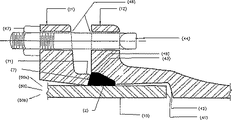
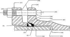
ガスケット2に当接して、締結装置44によってベル12に締結され、この締結装置44は、開口46に挿通されてナット47に係合するボルトとしてここに記載されている。明らかなように、ナット47の引き付けすなわち締付けによって、ガスケット押え11がガスケット2に押付けられて、これを圧縮する。オーバーセンタクランプ、カムロック、傾斜した楔、傾斜した環状リング及びリベット等の他の締付け手段が当業者には明らかであり、ガスケット押え11とベル12との間の軸方向の間隔を減少させるために使用できるあらゆる機構がここに含まれる。凹部シート43とガスケット押え11との強制によって、ガスケット2の変形が主に径方向内側へ向けられて、スピゴット10とのシール係合に向けられる。ここに開示された発明は、この相互関係を構築し、スピゴット、ベル又はガスケット押えの変更を必要とせず、そのような修正が別途望まれたならば、そのような変更を本発明の範囲に含ませることができる。
AWWA C111/A21.11−95の全ての要求に合致する。特に、あらゆる所与のスピゴット10に対して、ガスケット2は、スピゴット10の外径よりも僅かに小さい内径を有する。したがって、スピゴット10の外側のガスケット2の配置は、一般的に、ガスケット2を拡張してスピゴット10の周りに密着させる力を生じることを要求する。
Claims (15)
- ガスケット押えを使用して雄管部分を雌管部分に接続するとき、スタッフィングボックスアセンブリ内で使用するための拘束ガスケットであって、
a)スピゴット−対向表面と、組立状態において前記雌管部分の内側表面に対向する径方向外側表面と、ガスケット押え−対向表面と、前記径方向外側表面に径方向内向きに配置された溝とを有する圧縮可能な本体と、
b)歯部及び該歯部の径方向外側に配置された上部突起を有し、前記ガスケット押えによって当該拘束ガスケットが圧縮されたとき、前記圧縮可能な本体に対して回転して、前記歯部の少なくとも一部が前記雄管部分に係合し、前記上部突起の少なくとも一部が前記雌管部分に係合するように配置されたロック部材とを備えていることを特徴とする拘束ガスケット。 - 前記溝は、当該ガスケットの前部と前記ロック部材の径方向最も外側の領域との間に配置されていることを特徴とする請求項1に記載の拘束ガスケット。
- 前記溝は、前記径方向外側表面の外形の一部を形成することを特徴とする請求項1に記載の拘束ガスケット。
- 前記径方向外側表面は、圧縮シート表面及び歪制御表面を含み、前記歪制御表面は、前記溝内へ通じ、当該ガスケットの中心軸に対して5度から20度の間の角度で配置されていることを特徴とする請求項3に記載の拘束ガスケット。
- 前記溝は、前記径方向外側表面の下方の空隙であることを特徴とする請求項1に記載の拘束ガスケット。
- 更に、変形特性の異なる複数の領域を備え、該領域の変形特性によって前記ロック部材を移動させることを特徴する請求項1に記載の拘束ガスケット。
- a)ガスケットの一部をベルとスピゴットとの間にシール関係で押込み、
b)ステップ(a)の後に、前記ガスケットを圧縮して、該ガスケットの溝の少なくとも一部を潰し、
c)ステップ(b)の開始の後に、ロック部分を回動させて前記ベルと前記スピゴットとの間に抵抗をもって接触させるステップを備えることを特徴とする拘束メカニカル継手の組付方法。 - 前記溝は、前記ガスケットの径方向外側表面の下方の空隙であることを特徴とする請求項7に記載の組付方法。
- 前記溝は、前記ガスケットの径方向外側表面の環状の凹みであることを特徴とする請求項7に記載のアセンブリ方法。
- 圧縮に応答して変形したとき、その圧力中心が変化することにより、内部に埋め込まれたロックセグメントを回転させることを特徴とするスタッフィングボックスアセンブリ内で使用するための拘束ガスケット。
- 圧力中心は、圧縮可能な空隙又は溝によって変化することを特徴とする請求項10に記載の拘束ガスケット。
- 径方向内側に少なくとも1つの歯が配置されたロックセグメントを備えていることを特徴とする請求項10に記載の拘束ガスケット。
- 前記ロックセグメントは、径方向内側に配置された複数の歯を備え、該歯の少なくとも2つの間の領域は、ガスケット材料が欠けていることを特徴とする請求項12に記載の拘束ガスケット。
- 雄管部分を雌管部分に接続するとき、スタッフィングボックスアセンブリ内で使用する拘束ガスケットとガスケット押えとの組合わせであって、
前記ガスケット押えは、前記雌管部分に堅固に結合され、前記拘束ガスケットは、
a)スピゴット−対向表面と、径方向外側表面と、前記ガスケット押えに接続するガスケット押え−対向表面と、径方向外側表面において、前記拘束ガスケットを間に入れて前記ガスケット押えを前記雌管部分に連結したとき、前記雌管部分に当接する表面と、ロック部材の径方向最も外側の領域との間に配置された径方向内向きの溝とを有する変形可能な本体と、
b)少なくとも一部が前記溝と前記ガスケット押え−対向表面との間に配置され、歯部及び前記本体に埋め込まれた本体部分を有し、前記ガスケット押えによって前記拘束ガスケットが圧縮されたとき、回転して前記歯部の少なくとも一部が前記雄管部に係合するように配置された前記ロック部材とを備えていることを特徴とする拘束ガスケットとガスケット押えとの組合わせ。 - スタッフィングボックスアセンブリ内で使用する拘束ガスケットとガスケット押えとの組合わせであって、
前記拘束ガスケットは、ロックセグメントを含み、前記ガスケット押えのベルへの締付けに応答する変形によって、その圧力中心が変化して、変形の段階中にロックセグメントが軸方向に移動し、変形の次の段階で、続いて前記ロックセグメントが回転し、
ロックセグメントは、径方向内側に面した少なくとも1つの歯部を有し、また、前記拘束ガスケットの溝がつぶれることによって、前記ロックセグメントの径方向外側端部が径方向内側端部よりも大きく移動するように前記拘束ガスケット内に配置されていることを特徴とする拘束ガスケットとガスケット押えとの組合わせ。
Applications Claiming Priority (1)
| Application Number | Priority Date | Filing Date | Title |
|---|---|---|---|
| PCT/US2003/032648 WO2005047745A2 (en) | 2003-10-15 | 2003-10-15 | Energized restraining gasket for mechanical joints of pipes |
Publications (2)
| Publication Number | Publication Date |
|---|---|
| JP2007521443A JP2007521443A (ja) | 2007-08-02 |
| JP4411489B2 true JP4411489B2 (ja) | 2010-02-10 |
Family
ID=34589271
Family Applications (1)
| Application Number | Title | Priority Date | Filing Date |
|---|---|---|---|
| JP2005510604A Expired - Fee Related JP4411489B2 (ja) | 2003-10-15 | 2003-10-15 | 管のメカニカル継手用の付勢拘束ガスケット |
Country Status (8)
| Country | Link |
|---|---|
| EP (1) | EP1673568A4 (ja) |
| JP (1) | JP4411489B2 (ja) |
| CN (1) | CN100504133C (ja) |
| AU (1) | AU2003282837B2 (ja) |
| CA (2) | CA2536500C (ja) |
| MX (1) | MXPA06003795A (ja) |
| RU (1) | RU2336454C2 (ja) |
| WO (1) | WO2005047745A2 (ja) |
Families Citing this family (16)
| Publication number | Priority date | Publication date | Assignee | Title |
|---|---|---|---|---|
| US7104573B2 (en) | 2000-06-08 | 2006-09-12 | United States Pipe And Foundy Company, Llc | Energized restraining gasket for mechanical joints of pipes |
| US7108289B1 (en) | 2000-06-08 | 2006-09-19 | United States Pipe And Foundry Company, Llc | Restraining gasket for mechanical joints of pipes |
| WO2005031174A2 (en) | 2003-09-25 | 2005-04-07 | United States Pipe And Foundry Company, Llc | Centroidally twistable compression ring for pipe joints |
| FR2907877B1 (fr) * | 2006-10-31 | 2012-06-22 | Saint Gobain Pont A Mousson | Jonction tubulaire |
| CN103148293B (zh) * | 2009-01-27 | 2015-07-29 | 株式会社久保田 | 管接头 |
| UA92680C2 (uk) * | 2009-05-05 | 2010-11-25 | Открытое Акционерное Общество "Укргидропроект" | Конструкція напірних сталезалізобетонних (залізобетонних) водоводів в м'яких ґрунтах |
| US20110291409A1 (en) * | 2010-06-01 | 2011-12-01 | Kennedy Jr Harold | Pipe Gripping Elements with Buttress Pockets and Pipe Joint Restraints Incorporating Same |
| CN102683571A (zh) * | 2012-05-31 | 2012-09-19 | 华南理工大学 | 一种大功率led散热结构 |
| CN104913132B (zh) | 2014-03-10 | 2019-05-10 | 科斯摩工机股份有限公司 | 流体管的脱离防止装置和管接头 |
| WO2017169531A1 (ja) * | 2016-03-28 | 2017-10-05 | 株式会社クボタ | 管継手、離脱防止部材および管の接合方法 |
| US11774012B2 (en) | 2018-09-18 | 2023-10-03 | Asml Netherlands B.V. | Apparatus for high pressure connection |
| CN109084105B (zh) * | 2018-10-26 | 2023-08-29 | 江苏格睿特管网工程有限公司 | 钢筋混凝土推进管环槽型接头连接结构 |
| CA3057911A1 (en) | 2019-10-08 | 2021-04-08 | Ipex Technologies Inc. | Push-fit pipe fitting |
| US11204114B2 (en) | 2019-11-22 | 2021-12-21 | Trinity Bay Equipment Holdings, LLC | Reusable pipe fitting systems and methods |
| CN113738983B (zh) * | 2020-12-11 | 2023-03-24 | 上海威逊机械连接件有限公司 | 快装式管件组件及其应用 |
| CN114662345B (zh) * | 2022-05-23 | 2022-08-05 | 中国二十二冶集团有限公司 | 大直径虾壳弯管制作方法 |
Family Cites Families (11)
| Publication number | Priority date | Publication date | Assignee | Title |
|---|---|---|---|---|
| NL107650C (ja) * | 1956-05-28 | |||
| BE668603A (ja) * | 1964-08-20 | |||
| US3726549A (en) * | 1971-09-15 | 1973-04-10 | E Bradley | Pipe joint retainer gland |
| DE3336855A1 (de) * | 1983-10-11 | 1985-04-25 | Thyssen Industrie Ag, 4300 Essen | Schubgesicherte steckverbindung fuer rohre, insbesondere muffenrohre |
| US5219189A (en) * | 1989-12-11 | 1993-06-15 | Pont-A-Mousson S.A. | Composite gasket for the locked assembly of spigot and socket pipes |
| US5067751A (en) * | 1990-07-27 | 1991-11-26 | American Cast Iron Pipe Company | Gasket for field adaptable push-on restrained joint and joint thus produced |
| FR2683609B1 (fr) * | 1991-11-07 | 1995-01-20 | Pont A Mousson | Joint verrouille pour canalisations. |
| US5464228A (en) * | 1992-11-04 | 1995-11-07 | United States Pipe And Foundry Company | Restraining element for pressure pipe joints |
| FR2708077B1 (fr) * | 1993-07-23 | 1995-09-22 | Pont A Mousson | Insert de verrouillage électriquement isolant pour garniture d'étanchéité, garniture d'étanchéité correspondante, et procédé de fabrication de tels inserts. |
| FR2766552B1 (fr) * | 1997-07-25 | 1999-09-03 | Pont A Mousson | Dispositif pour l'assemblage de deux elements de canalisation, et assemblages d'elements de canalisation en comportant application |
| US20020017789A1 (en) * | 1999-06-16 | 2002-02-14 | Holmes William W. | Gland pipe fitting |
-
2003
- 2003-10-15 WO PCT/US2003/032648 patent/WO2005047745A2/en not_active Ceased
- 2003-10-15 JP JP2005510604A patent/JP4411489B2/ja not_active Expired - Fee Related
- 2003-10-15 CA CA2536500A patent/CA2536500C/en not_active Expired - Lifetime
- 2003-10-15 RU RU2006110374/06A patent/RU2336454C2/ru active
- 2003-10-15 CN CNB2003801105049A patent/CN100504133C/zh not_active Expired - Lifetime
- 2003-10-15 AU AU2003282837A patent/AU2003282837B2/en not_active Expired
- 2003-10-15 MX MXPA06003795A patent/MXPA06003795A/es active IP Right Grant
- 2003-10-15 EP EP03774835A patent/EP1673568A4/en not_active Withdrawn
- 2003-10-15 CA CA2709737A patent/CA2709737C/en not_active Expired - Lifetime
Also Published As
| Publication number | Publication date |
|---|---|
| AU2003282837A1 (en) | 2004-06-06 |
| WO2005047745A2 (en) | 2005-05-26 |
| CN100504133C (zh) | 2009-06-24 |
| AU2003282837B2 (en) | 2010-03-04 |
| CA2536500A1 (en) | 2005-05-26 |
| CA2709737C (en) | 2012-09-25 |
| CA2709737A1 (en) | 2005-05-26 |
| JP2007521443A (ja) | 2007-08-02 |
| EP1673568A2 (en) | 2006-06-28 |
| CA2536500C (en) | 2010-11-02 |
| AU2003282837A8 (en) | 2005-06-06 |
| MXPA06003795A (es) | 2006-06-14 |
| WO2005047745A3 (en) | 2005-08-18 |
| RU2336454C2 (ru) | 2008-10-20 |
| RU2006110374A (ru) | 2007-11-20 |
| CN1860321A (zh) | 2006-11-08 |
| EP1673568A4 (en) | 2010-07-07 |
Similar Documents
| Publication | Publication Date | Title |
|---|---|---|
| US7104573B2 (en) | Energized restraining gasket for mechanical joints of pipes | |
| JP4411489B2 (ja) | 管のメカニカル継手用の付勢拘束ガスケット | |
| US7108289B1 (en) | Restraining gasket for mechanical joints of pipes | |
| JP5681229B2 (ja) | 管継手 | |
| EP1180630B1 (en) | Pipe coupler and method of coupling | |
| US4097074A (en) | Pipe joint construction | |
| US4040651A (en) | Self-locking pipe coupling | |
| GB2218768A (en) | Pipe coupling with compressible sleeve | |
| JP2001330185A (ja) | 耐震継手ならびに耐震管路 | |
| GB2303677A (en) | Pipe coupling | |
| EP1164325A2 (en) | Pipe coupling | |
| JPS60245891A (ja) | スラスト力から保護した密閉プラスチツク管ソケツト結合装置 | |
| JP3479354B2 (ja) | 管接続構造 | |
| JP2537578B2 (ja) | 管継手 | |
| EP0044719A1 (en) | Improvements in apparatus for sealing pipes | |
| KR20060038484A (ko) | 파이프의 기계적 조인트를 위한 구속 개스킷 | |
| CN211735676U (zh) | 一种柔性密封锁环连接套及连接结构 | |
| JP3861203B2 (ja) | 伸縮可撓管継手の仮締用スペーサ及び仮締構造 | |
| JP3650904B2 (ja) | 耐震異形管継手 | |
| EP0312317A2 (en) | Pipe couplings | |
| JPH08247359A (ja) | 管継手用管離脱防止装置 | |
| JP3197655B2 (ja) | 管継ぎ手構造 | |
| JPH11270764A (ja) | 管継手構造 | |
| JP2025060432A (ja) | 管継手の止水構造及びこれに用いるゴム輪 | |
| PL206982B1 (pl) | Uszczelka blokująca |
Legal Events
| Date | Code | Title | Description |
|---|---|---|---|
| A131 | Notification of reasons for refusal |
Free format text: JAPANESE INTERMEDIATE CODE: A131 Effective date: 20081126 |
|
| A601 | Written request for extension of time |
Free format text: JAPANESE INTERMEDIATE CODE: A601 Effective date: 20090226 |
|
| A602 | Written permission of extension of time |
Free format text: JAPANESE INTERMEDIATE CODE: A602 Effective date: 20090305 |
|
| A601 | Written request for extension of time |
Free format text: JAPANESE INTERMEDIATE CODE: A601 Effective date: 20090325 |
|
| A602 | Written permission of extension of time |
Free format text: JAPANESE INTERMEDIATE CODE: A602 Effective date: 20090401 |
|
| A601 | Written request for extension of time |
Free format text: JAPANESE INTERMEDIATE CODE: A601 Effective date: 20090427 |
|
| A602 | Written permission of extension of time |
Free format text: JAPANESE INTERMEDIATE CODE: A602 Effective date: 20090508 |
|
| A521 | Request for written amendment filed |
Free format text: JAPANESE INTERMEDIATE CODE: A523 Effective date: 20090522 |
|
| TRDD | Decision of grant or rejection written | ||
| A01 | Written decision to grant a patent or to grant a registration (utility model) |
Free format text: JAPANESE INTERMEDIATE CODE: A01 Effective date: 20091007 |
|
| A01 | Written decision to grant a patent or to grant a registration (utility model) |
Free format text: JAPANESE INTERMEDIATE CODE: A01 |
|
| A61 | First payment of annual fees (during grant procedure) |
Free format text: JAPANESE INTERMEDIATE CODE: A61 Effective date: 20091102 |
|
| FPAY | Renewal fee payment (event date is renewal date of database) |
Free format text: PAYMENT UNTIL: 20121127 Year of fee payment: 3 |
|
| R150 | Certificate of patent or registration of utility model |
Free format text: JAPANESE INTERMEDIATE CODE: R150 |
|
| LAPS | Cancellation because of no payment of annual fees |