JP4408539B2 - Thermostat case structure - Google Patents
Thermostat case structure Download PDFInfo
- Publication number
- JP4408539B2 JP4408539B2 JP2000223311A JP2000223311A JP4408539B2 JP 4408539 B2 JP4408539 B2 JP 4408539B2 JP 2000223311 A JP2000223311 A JP 2000223311A JP 2000223311 A JP2000223311 A JP 2000223311A JP 4408539 B2 JP4408539 B2 JP 4408539B2
- Authority
- JP
- Japan
- Prior art keywords
- case
- thermostat
- flow path
- hole
- coolant
- Prior art date
- Legal status (The legal status is an assumption and is not a legal conclusion. Google has not performed a legal analysis and makes no representation as to the accuracy of the status listed.)
- Expired - Fee Related
Links
Images


Classifications
-
- F—MECHANICAL ENGINEERING; LIGHTING; HEATING; WEAPONS; BLASTING
- F01—MACHINES OR ENGINES IN GENERAL; ENGINE PLANTS IN GENERAL; STEAM ENGINES
- F01P—COOLING OF MACHINES OR ENGINES IN GENERAL; COOLING OF INTERNAL-COMBUSTION ENGINES
- F01P7/00—Controlling of coolant flow
- F01P7/14—Controlling of coolant flow the coolant being liquid
- F01P7/16—Controlling of coolant flow the coolant being liquid by thermostatic control
-
- F—MECHANICAL ENGINEERING; LIGHTING; HEATING; WEAPONS; BLASTING
- F01—MACHINES OR ENGINES IN GENERAL; ENGINE PLANTS IN GENERAL; STEAM ENGINES
- F01P—COOLING OF MACHINES OR ENGINES IN GENERAL; COOLING OF INTERNAL-COMBUSTION ENGINES
- F01P2070/00—Details
Description
【0001】
【発明の属する技術分野】
本発明は、内燃機関内に配置され、冷却液流路間を遮断、連通することにより、冷却液の流れを制御するサーモスタットのケース構造に関し、特にサーモスタットを構成するケースを有効利用したサーモスタットのケース構造に関する。
【0002】
【従来の技術】
現在市販されている車両の内燃機関の冷却システムは、冷却液を媒体とする水冷方式によりエンジンを冷却するものが大半を占め、この水冷方式の冷却システムは、四輪車用のエンジンの他、広く二輪車用のエンジンにも供されている。
前記水冷方式による車両の内燃機関の冷却システムは、エンジン本体の外部にラジエ−タを配置し、このラジエ−タとエンジン本体とをラバ−ホ−ス等により連結して冷却液を循環させるものであり、熱交換器の役割を担うラジエ−タと、このラジエ−タにエンジンから冷却液を強制的に圧送するウォ−タ−ポンプと、ラジエ−タから流れてくる、若しくはラジエ−タへ流れていく冷却液の流れを制御して適温に保つサ−モスタットと、冷却液の循環流路を形成するラバ−ホ−ス等とから構成されている。
そして、エンジンの発熱によるオ−バ−ヒ−トを防止するとともに、一方では寒い時期のオ−バ−ク−ルを防止して、エンジンを常に適温に保つように機能する。
【0003】
このような水冷方式に用いられる、一般的なサ−モスタット及びサ−モスタット取り付け構造について、図10及び図11に基づいて説明する。図10は、内燃機関の冷却液流路に従来のサ−モスタットを取り付けた状態を示す模式図であり、図11は図10におけるサ−モスタットの取り付け部の拡大図である。
【0004】
図10に示すように、サ−モスタット100はエンジンE本体とラジエ−タRとの間に形成される冷却液流路110の所定位置に配置されている。また図11に示すように、このサ−モスタット100には、エレメント101の作用によって進退動するピストン102が設けられ、前記サ−モスタット100は、そのピストン102の進退方向が冷却液の流路方向と平行となるように冷却液流路110に配置される。
そして、前記サ−モスタット100では、前記ピストン102の進退動によって弁体103と弁座104との当接、離間が行われ、冷却液流路の遮断、連通が行われる。
なお、図11中の符号105は、ピストン102の進退動を案内するガイド部であり、符号106は、ワックスを収納したワックスケ−スであり、符号107は、バイパス通路110Aを遮断、連通する第2の弁体である。また、図10の符号Pは、ウォ−タ−ポンプであり、符号Rは、ラジエータである。
【0005】
ここで、前記サ−モスタット100の動作について説明すると、図10(a)に示すように、エンジン始動時からエンジンE内が適温になるまでの間、サ−モスタット100は、冷却液流路110を閉ざしている。
即ち、エンジンEからの冷却液は、ラジエ−タRへは向かわず、バイパス通路110Aを通ってエンジンEへ循環するため(同図(a)矢印参照)、早期に適温に達する。
一方、エンジンE内が適温になった後は、図10(b)に示すように、サ−モスタット100の弁体103が開き、ラジエ−タR側の冷却液流路110を開く。その結果、冷却液がラジエ−タRを通ってエンジンEへの循環し(同図(b)矢印参照)、エンジンE内は冷却され、適温に保たれる。
【0006】
【発明が解決しようとする課題】
しかしながら、前記した従来のサ−モスタットは冷却液流路内部に置かれるため、冷却液流路の流量を所定量に保つには、サ−モスタットを配置する冷却液流路の管径を太くしなければならなかった。その結果、冷却液流路の管径を太くしなければならず、効率的なレイアウトを行うことができなかった。また、サ−モスタットを配置する場所にも多くの制限があり、更にサ−モスタットの取付け作業も困難であった。
かかる問題を解決するために、エンジンヘッドに形成された冷却液流路を横切って形成される嵌合孔に埋設配置される埋設式サ−モスタットを提案した(特許願平11−17923号)。
【0007】
ところで、従来の車両の内燃機関の冷却システムには、液温センサーを設け、冷却液が所定の温度を越えた場合にはラジエータに設けられた電動冷却ファンを駆動させるものがある。この液温センサーはサ−モスタットとは別に設けられている。
そのため、前記液温センサーを設けるための設置場所を確保する必要があり、またその取付け作業が必要であった。
また、ラジエータ、ウォータジャケットに冷却液を注入する際、いわゆるエアー抜きを行う必要がある。車両の内燃機関の冷却システムにおいて、エアー抜きを行うため、従来からいわゆるジグルバルブが設けられているが、このジグルバルブについても液温センサーと同様、設置場所を確保する必要があり、またその取付け作業が必要であった。
【0008】
本発明は、前記課題を解決するためになされたものであり、サ−モスタットをエンジンヘッド等の被取付け部材に埋め込むことによって冷却液流路の効率的なレイアウトを可能とし、またサ−モスタットの取付け作業も容易に行うことができ、更にはサ−モスタットのケースを有効に利用し、液温センサー、ジグルバルブ等を容易に取り付けることができるサ−モスタットのケース構造を提供することを目的とする。
【0009】
【課題を解決するための手段】
前記課題を解決するためになされた本発明にかかるサーモスタットのケース構造は、周面に入口開口部と出口開口部が形成された筒形状のケースと、前記入口開口部と前記出口開口部とを前記ケース内で連通する流路領域と、前記流路領域を流れる冷却液の温度変化に応じて前記流路領域を横断すべく進退動し、この進退動によって前記流路領域の遮断、連通を行う弁体とを備え、冷却液流路が形成された被取付け部材の嵌合孔に埋設されるサーモスタットのケース構造において、前記ケースは、ケース上端面から突出して形成された円筒状のキャップ部と、前記ケースの上端面とキャップ部とを連結する連結部とを備え、筒形状のケースの側壁、キャップ部、連結部のいずれかに貫通孔が形成され、前記ケースの貫通孔に、サーモスタットに取り付けられた電子部品の接続コードが挿通していることを特徴としている。
また、前記課題を解決するためになされた本発明にかかるサーモスタットのケース構造は、周面に入口開口部と出口開口部が形成された筒形状のケースと、前記入口開口部と前記出口開口部とを前記ケース内で連通する流路領域と、前記流路領域を流れる冷却液の温度変化に応じて前記流路領域を横断すべく進退動し、この進退動によって前記流路領域の遮断、連通を行う弁体とを備え、冷却液流路が形成された被取付け部材の嵌合孔に埋設されるサーモスタットのケース構造において、前記ケースは、ケース上端面から突出して形成された円筒状のキャップ部と、前記ケースの上端面とキャップ部とを連結する連結部とを備え、筒形状のケースの側壁、キャップ部、連結部のいずれかに貫通孔が形成され、ジグルボールと前記ジグルボールを収容するジグルボール収容部を備えたシグルバルブが、前記ケースの貫通孔に設けられていることを特徴としている。
更に、周面に入口開口部と出口開口部が形成された筒形状のケースと、前記入口開口部と前記出口開口部とを前記ケース内で連通する流路領域と、前記流路領域を流れる冷却液の温度変化に応じて前記流路領域を横断すべく進退動し、この進退動によって前記流路領域の遮断、連通を行う弁体とを備え、冷却液流路が形成された被取付け部材の嵌合孔に埋設されるサーモスタットのケース構造において、前記ケースは、ケース上端面から突出して形成された円筒状のキャップ部と、前記ケースの上端面とキャップ部とを連結する連結部とを備え、筒形状のケースの側壁、キャップ部、連結部のいずれかに貫通孔が形成され、弁体と前記弁体が両端に形成されたジグルピンとを備えたシグルバルブが、前記ジグルピンが前記ケースの貫通孔を挿通することによって装着されることを特徴としている。
【0010】
このように、サーモスタットのケースに貫通孔が形成されているため、サーモスタットに液温センサー、ジグルバルブ等を取り付けることができ、冷却システムにサーモスタットを取り付けると同時に、液温センサー、ジグルバルブ等を取り付けることができる。なお、サーモスタットが、冷却液流路が形成された被取付け部材の嵌合孔に埋設されるため、サーモスタットを容易に取り付けることができ、しかも効率的なレイアウトを行うことができる。
【0012】
また、サーモスタットに取り付けられた電子部品、例えば、冷却液の液温を検知する液温センサー、あるいはまたワックスケースを強制的に加熱するPTC、ニクロムヒータのような熱電素子等の電子部品の接続コードが貫通孔を挿通している場合には、サーモスタットを被取付け部材に取り付けることによって、同時に電子部品の取り付け、配線を行うことができる。
【0014】
【発明の実施の形態】
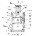
本発明にかかる第1の実施形態について、図1乃至図6に基づいて説明する。なお、図1は、第1の実施形態にかかる埋設式のサ−モスタットの平面図であり、図2は、図1に示された埋設式サ−モスタットの正面図であり、図3は、図1に示された埋設式サ−モスタットの側面図であり、図4は図1に示された埋設式サ−モスタットの縦断面図である。また図5、図6は埋設式サ−モスタットを内燃機関内に設置した状態を示す縦断面図であり、図5は、流路領域を遮断している状態を示し、図6は、流路領域を連通している状態を示す。
【0015】
この埋設式サ−モスタットAは、ケース1と、前記ケース1内に収装されたサ−モバルブ2と、前記サ−モバルブ2を加熱することによって強制的に動作させる熱電素子10と、被取付け部材であるエンジンヘッドBと螺合しケース1の底面を閉塞する蓋体3と、サ−モバルブ2と蓋体3との間に介装され、サ−モバルブ2を上方に押圧するコイルスプリング4とから構成されている。
前記ケース1は中空筒形状を有し、図5、図6に示すようにエンジンヘッドBに形成された冷却液流路Cに対応して、入口開口部1aと出口開口部1bが形成されている。また、前記ケース1の周面(側壁)1cの入口開口部1bの下方位置に、熱電素子10に接続された接続コード10aをケース1の周面(側壁)1cの外側に導出させるための貫通孔1dが形成されている。
【0016】
また、前記ケース1の周面(側壁)1cの出口開口部1bの下方位置にはバイパス通路用の出口開口部1fが形成され、一方、ケース1の底面にバイパス通路用の入口開口部1eが形成されている。前記バイパス通路用の入口開口部1eと出口開口部1fは、図5に示すように後述するエレメント(弁体)2aが入口開口部1a、出口開口部1bを閉塞しているとき、連通するように構成されている。また、ケース1の下端部内壁の凹部1gには、コイルスプリング4を支持する金属製のリング5が嵌合されている。
【0017】
前記ケース1の上部1hには、周面(側壁)1cと同心円であって、かつ周面(側壁)1cより小径のキャップ部1iが、ケース1と一体に形成されている。また、ケース1の上部1hには、ケース1の上面とキャップ部1iとを連結する連結部1jが設けられている。この連結部1jは、図2に示すように、入口開口部1aと出口開口部1bの中間位置に設けられている。即ち、入口開口部側1aと出口開口部側1bを仕切るように構成されている。
【0018】
また、前記ケース1の周面(側壁)1c、連結部1jの稜線部1j1 、キャップ部1iの上端面1i1 に、繋がった直線状の溝1kが形成され、前記溝1kには、リング状形状のゴム部材6が嵌合している。なお、ケース1の底部にも溝1kが形成され、リング状形状のゴム部材6が必要以上に突出しないようになされている。
更に、前記ケース1の冷却液流路Cの入口開口部1aの下方向位置(下端部)には、位置決用の突起部1lが設けられている。またこの突起部1lに対応して、エンジンヘッドBに設けられた嵌合穴7の側壁には凹部7aが設けられ、前記突起部1lが凹部7aに係止される。また、前記ケース1の底面は、シール部材8を介してバイパス通路3aが形成された蓋体3によって、閉塞されている。
【0019】
また、前記サ−モバルブ2について詳述すると、サ−モバルブ2は、膨張体であるワックス2bを内装するワックスケ−ス2cと、ワックス2bの膨張収縮を上層の半流動体2dに伝達するダイヤフラム2eと、ダイヤフラム2eの応動を上層のラバ−ピストン2fに伝達する半流動体2dと、半流動体2dの応動を上層のピストン2gに伝達するバックアッププレ−ト2hと、キャップ部を押圧するピストン2gと、これらの構成部位を積層状に内装するエレメント(弁体)2aから構成されている。そして、前記エレメント(弁体)2aは、ケース1の内壁面1mに沿って、摺動自在に構成され、入口開口部1aと出口開口部1bを開閉するように構成されている。
【0020】
前記サ−モバルブ2(ワックスケ−ス2c)の底面には、ワックスケ−ス2cを加熱することによって前記ワックス2bを強制的に膨張させる熱電素子10が設けられている。この熱電素子10には電源と接続するための接続コード10aが接続され、この接続コード10aは前記したように貫通孔1dを介して、ケース1の外部に導出されている。ここで、熱電素子とは、例えば、PTC、ニクロムヒータのような加熱素子をいう。
【0021】
なお、ワックスケ−ス2cの底部側と対峙する上部側には、ピストン2gの案内部であるガイド部2c1 が形成されている。このガイド部2c1 の外周部は、キャップ部の内壁面1nの形状に対応して形成されており、この内壁面1nに対して摺動可能に構成されている。
【0022】
また、前記コイルスプリング4は、リング5とサ−モバルブ2の空隙に介装されており、サ−モバルブ2本体を常時、上方方向に付勢するという作用をする(図4、図5参照)。なお、コイルスプリング4の弾性やコイルスプリング4の全高を変化させることにより、埋設式サ−モエレメント1の作動設定温度、流量等の条件を変化させる場合にも、適宜対応させることができる。
また、前記蓋体3には、図示しないが、ねじ部が形成されており、エンジンヘッドBに螺合することにより、シール部材8を介して蓋体3が固定される。
【0023】
続いて、サ−モスタットAの取り付け方法について、説明する。
まず、サ−モスタットAを組立て、熱電素子10の接続コード10aをケース1の貫通孔1aを介して外部に導出させる。また、予め、エンジンヘッドBには、予め上部嵌合穴9、下部嵌合穴7を形成する。
そして、前記上部嵌合穴9、下部嵌合穴7にサ−モスタットAのケース1を嵌め込む。この嵌め込みに際し、入口開口部1aと出口開口部1bが冷却液流路Cと連通するように、向きを合わせて位置合わせする必要がある(図5、図6参照)。そして、嵌合穴7、9にケース1を嵌合させた状態で、シール部材8を介して蓋体3をエンジンヘッドBに螺合させることにより、ケース1の底面を閉塞する。
【0024】
このとき、前記熱電素子10の接続コード10aは、ケース1の貫通孔1dを介してケース1の外部に導出され、前記嵌合穴7とケース1との間の隙間Sを通って、嵌合穴7から導出される。そしてシール部材8に形成された貫通孔、蓋体3の貫通孔を介して外部に導出され、電源に接続する。このように、サーモスタットを取り付けることにより、熱電素子10も同時に取り付けられる。また熱電素子10を取り付けるためのスペースを確保する必要もなく、設置の制約も受けない。
なお、このケース1が、エンジンヘッドBに組み込まれた状態にあっては、前記ゴム部材6が、上部嵌合穴9、嵌合穴7と密着するために、ケース1の周面1cと上部嵌合穴9、嵌合穴7の隙間を伝わって、冷却液が洩れ流れることはない。
【0025】
次に、本実施の形態に係るサ−モスタットAの作用について説明する。(図2、3参照)。まず、サ−モスタットAの閉状態から開状態への作用について説明する。暖機運転前の冷却液流路C内の冷却液は、低温であり、この温度はエレメント(弁体)2aの外周面とワックスケ−ス2cを介してワックスケ−ス2c内のワックス2bに伝播する(図5を参照)。
【0026】
そして、時間の経過と共に冷却液流路C内の冷却液の温度が上昇すると、ワックスケ−ス2c内のワックス2bは膨張して体積が増加し、この体積増加に伴ってダイヤフラム2eが上方へ膨れ上がる。その結果、上層の半流動体2dを介して、ラバ−ピストン2fを上方方向に押し上げようとする力が働く。この力が、バックアッププレ−ト2hを介してピストン2gに伝わり、ピストン2gがガイド部2c1 から突出しようとする。しかし、ピストン2gの先端部は、固着されたキャップ部に常時接触しているため、実際には、エレメント(弁体)2a自体が、コイルスプリング4の反発力に抗しながら、ピストン2gに対する相対移動によって押し下げられる。
【0027】
そして、サ−モバルブ2が下降摺動すると、エレメント(弁体)2aの外周面によって閉状態とされていたケース1の入口開口部1aと出口開口部1bは開放されて、流路領域FAが連通する。その結果、冷却液が、図6の帯矢印の如くラジエ−タ側からエンジン側に流れる。
【0028】
また、冷却液の液温と関係なく、強制的に閉状態から開状態になすためには、接続コード10aから電力を供給し、熱電素子10によってワックスケース2cを加熱し、ワックス2bを強制的に膨張させる。その結果、前記した動作と同様にして、ケース1の入口開口部1aと出口開口部1bは開放されて、流路領域FAが連通する。
【0029】
次に、サ−モスタットAの開状態から閉状態への作用について説明する。エンジンの運転を停止するとウォ−タ−ポンプの作動が停止し、冷却液流路C内の冷却液の循環が停止する。時間の経過と共に冷却液の温度が低下し、この温度変化はエレメント(弁体)2aとワックスケ−ス2cを介してワックス2bにも伝播される。そして、温度低下とともに膨張していたワックス2bは収縮し、サ−モバルブ2を常に上方に付勢するコイルスプリング4の付勢力によって、サ−モバルブ2は上方に摺動する。
その結果、エレメント(弁体)2aの外周面が、最終的にケース1の入口開口部1aと出口開口部1bを閉状態とし、流路領域FAを遮断する。(図5を参照)。
【0030】
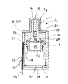
次に、本発明にかかる第2の実施形態について、図7に基づいて説明する。
なお、図7は埋設式サ−モスタットを内燃機関内に設置した状態を示す縦断面図であり、流路領域を遮断している状態を示している。
この実施形態は入口開口部1aに液温センサー11を配置し、前記液温センサー11の接続コード11aをケース1の側壁1cに形成された貫通孔1pを通して、外部に導出した点に特徴があり、他の構成は第1の実施形態と同一の構成を備えるため、その説明は省略する。
前記貫通孔1pは入口開口部1aからケース1の底面まで形成されており、前記底面に貫通孔1pの開口部が形成されている。したがって、貫通孔1pから導出された接続コード10aは、図示しないが、シール材8、蓋体3から外部に導出される。
【0031】
このように、液温センサー11が設けられたサ−モスタットAを内燃機関内に設置することによって、液温センサー11とサ−モスタットAとを同時に取り付けるつけることができる。また、液温センサー11を取りつけるためのスペースを確保する必要もなく、設置の制約も受けない。
【0032】
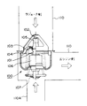
次に、本発明にかかる第3の実施形態について、図8に基づいて説明する。
図8(a)は、本発明にかかる第3の実施形態に示されたサ−モスタットの側面図であり、図8(b)は、本発明にかかる第3の実施形態に示されたサ−モスタットの正面図である。
この実施形態にあっては、ケース1の連結部1jに貫通孔1qが形成され、前記貫通孔1qにシグルバルブ12が設けられている点に特徴がある。前記シグルバルブ12は、弁体12a、12bと、前記弁体12a、12bが両端に形成されたジグルピン12cとを備えている。そして、前記ジグルピン12cが前記貫通孔1qに挿通することによって、ジグルバルブ12がケース1に装着される。なお、他の構成は第1の実施形態と同一の構成を備えるため、その説明は省略する。
【0033】
したがって、ケース1がエンジンヘッドBに嵌合した状態において、ケース周面1c、連結部1j、キャップ部1iの上面(ケース周面、連結部、キャップ部上面にかけられたゴム部材6)によって区切られた冷却液の入口開口部1a側と出口開口部1b側は、前記貫通孔1qによって連通し、前記弁体12a、12b(ジグルバルブ12)によって開放、閉塞がなされる。
この弁体12a、12b(ジグルバルブ12)は、冷却液を注入する際、エアーの逃げ道を形成するものであり、従来のジグルバルブと同様な作用をなすため、ここではその詳細な説明を省略する。
【0034】
このように、いわゆるジグルバルブ12が設けられたサ−モスタットAを内燃機関内に設置することによって、いわゆるジグルバルブ12とサ−モスタットAとを同時に取り付けるつけることができる。また、ジグルバルブ12を取りつけるためのスペースを確保する必要もなく、設置の制約も受けない。
【0035】
次に、本発明にかかる第4の実施形態について、図9に基づいて説明する。
なお、図9はサ−モスタットを内燃機関内に設置した状態を示す縦断面図であり、流路領域を遮断している状態を示している。
この実施形態にあっては、ケース1の側壁(周面)1cに貫通孔1rを形成し、前記貫通孔1rに、ジグルバルブ13を形成した点に特徴があり、他の構成は第1の実施形態と同一の構成を備えるため、その説明は省略する。
【0036】
前記ジグルバルブ13は、ジグルボール13aと、ジグルバルブ本体13bとから構成されている。前記ジグルバルブ本体13bは、前記ジグルボール13aを収容し、前記ジグルボール13aによって閉塞される外側開口部13c及び内側開口部13dが形成された収容部13eを備えている。そして、前記ジグルバルブ本体13bが、ケース1の側壁(周面)1cに貫通孔1rに嵌合され、ケース1に固定されている。
【0037】
したがって、前記ジグルボール13aが外側開口部13c、内側開口部13dを閉塞していない状態にあっては、前記収容部13eとケース1の内部と連通する。このジグルボール13aも前記した第3の実施形態における弁体12a、12b(ジグルバルブ12)と同様な機能を有し、冷却液を注入する際、エアーの逃げ道を形成するものであり、ここではその説明を省略する。
【0038】
このように、いわゆるジグルバルブ13が設けられたサ−モスタットAを内燃機関内に設置することによって、いわゆるジグルバルブ13とサ−モスタットAとを同時に取り付けるつけることができる。また、ジグルバルブを取りつけるためのスペースを確保する必要もなく、設置の制約も受けない。
【0039】
なお、上記実施形態において説明したサ−モスタットは、冷却液流路に適用される埋設式のサ−モスタットであるが、その配置位置はエンジンヘッドに限定されるものではなく、冷却液流路内であれば例えばエンジンブロック、ラジエ−タの内部、バイパス通路の分岐部位等の箇所であってもよい。
【0040】
【発明の効果】
本発明にかかるサ−モスタットのケース構造によれば、被取付け部材に埋め込むことによって、冷却液流路の効率的なレイアウトを行うことができ、またサ−モスタットの取付け作業も容易に行うことができる。
また、サ−モスタットのケースを有効に利用し、液温センサー、ジグルバルブ等を容易に、しかもサーモスタットの取り付けと同時に取り付けることができる。
【図面の簡単な説明】
【図1】図1は、第1の実施形態にかかる埋設式サ−モスタットの平面図である。
【図2】図2は、図1に示された埋設式サ−モスタットの正面図である。
【図3】図3は、図1に示された埋設式サ−モスタットの側面図である。
【図4】図4は、図1に示された埋設式サ−モスタットの縦断面図である。
【図5】図5は、埋設式サ−モスタットを内燃機関内に設置した状態を示す縦断面図であり、流路領域を遮断している状態を示す図である。
【図6】図6は、埋設式サ−モスタットを内燃機関内に設置した状態を示す縦断面図であり、流路領域を連通している状態を示す図である。
【図7】図7は、第2の実施の形態に係るサーモスタットの縦断面図である。
【図8】図8は、第3の実施の形態に係るサーモスタットを示す図である。
【図9】図9は、第4の実施の形態に係るサーモスタットをを示す図である。
【図10】一般的な内燃機関の冷却液流路に従来のサーモスタットを取り付けた状態を示す模式図である。
【図11】図10におけるサーモスタットの取り付け部の拡大図である。
【符号の説明】
A サーモスタット
B エンジンヘッド
1 ケース
1a 入口開口部
1b 出口開口部
1d 貫通孔
1j 連結部
1p 貫通孔
1q 貫通孔
1r 貫通孔
2 サーモバルブ
2a エレメント(弁体)
3 蓋体
4 コイルスプリング
5 リング
8 シール部材
10 熱電素子
10a 接続コード
12 ジグルバルブ
12a、12b 弁体
12c ジグルピン
13 ジグルバルブ
13a ジグルボール
13b ジグルバルブ本体
13c 外側開口部
13d 内側開口部
13e 収容部[0001]
BACKGROUND OF THE INVENTION
The present invention relates to a case structure of a thermostat that is disposed in an internal combustion engine and controls the flow of a coolant by blocking and communicating between coolant flow paths, and in particular, a case of a thermostat that effectively uses a case constituting a thermostat. Concerning structure.
[0002]
[Prior art]
Most of the cooling systems for internal combustion engines of vehicles currently on the market cool the engine by a water cooling method using a coolant as a medium, and this water cooling type cooling system is an engine for four-wheeled vehicles, Widely used for motorcycle engines.
In the cooling system for an internal combustion engine of a vehicle by the water cooling method, a radiator is disposed outside the engine body, and the radiator and the engine body are connected by a rubber hose to circulate the coolant. A radiator that plays the role of a heat exchanger, a water pump that forcibly pumps the coolant from the engine to the radiator, and a flow from or to the radiator It is composed of a thermostat that controls the flow of the flowing coolant and keeps it at an appropriate temperature, and a rubber hose that forms a circulation channel for the coolant.
In addition, overheat due to heat generation of the engine is prevented, and on the other hand, overcooling in a cold period is prevented to function to keep the engine at an appropriate temperature.
[0003]
A general thermostat and thermostat mounting structure used in such a water cooling system will be described with reference to FIGS. FIG. 10 is a schematic view showing a state where a conventional thermostat is attached to the coolant flow path of the internal combustion engine, and FIG. 11 is an enlarged view of a thermostat attachment portion in FIG.
[0004]
As shown in FIG. 10, the
In the
In FIG. 11,
[0005]
Here, the operation of the
That is, the coolant from the engine E does not go to the radiator R, but circulates to the engine E through the
On the other hand, after the inside of the engine E reaches an appropriate temperature, as shown in FIG. 10B, the valve body 103 of the
[0006]
[Problems to be solved by the invention]
However, since the above-described conventional thermostat is placed inside the cooling liquid flow path, in order to keep the flow rate of the cooling liquid flow path at a predetermined amount, the pipe diameter of the cooling liquid flow path in which the thermostat is arranged is increased. I had to. As a result, the pipe diameter of the coolant channel must be increased, and an efficient layout could not be performed. In addition, there are many restrictions on the location where the thermostat is placed, and it is difficult to install the thermostat.
In order to solve such a problem, an embedded thermostat has been proposed (Patent Application No. 11-17923) embedded in a fitting hole formed across a coolant flow path formed in the engine head.
[0007]
By the way, a conventional cooling system for an internal combustion engine of a vehicle includes a liquid temperature sensor that drives an electric cooling fan provided in a radiator when the coolant exceeds a predetermined temperature. This liquid temperature sensor is provided separately from the thermostat.
Therefore, it is necessary to secure an installation place for providing the liquid temperature sensor, and it is necessary to perform the installation work.
In addition, when the coolant is injected into the radiator and the water jacket, it is necessary to perform so-called air venting. A so-called jiggle valve is conventionally provided in order to vent the air in a cooling system for an internal combustion engine of a vehicle. However, as with a liquid temperature sensor, it is necessary to secure an installation place for this jiggle valve, and the installation work thereof is also difficult. It was necessary.
[0008]
The present invention has been made in order to solve the above-described problems. By embedding a thermostat in a member to be attached such as an engine head, an efficient layout of the coolant flow path is enabled. An object of the present invention is to provide a thermostat case structure that can be easily attached and that can effectively use a thermostat case and can easily attach a liquid temperature sensor, a jiggle valve, and the like. .
[0009]
[Means for Solving the Problems]
The thermostat case structure according to the present invention made to solve the above problems includes a cylindrical case in which an inlet opening and an outlet opening are formed on a peripheral surface, and the inlet opening and the outlet opening. The flow path area communicating in the case and the forward and backward movement to cross the flow path area according to the temperature change of the coolant flowing through the flow path area, and the forward and backward movements block and communicate the flow path area. A thermostat case structure embedded in a fitting hole of a mounted member in which a coolant flow path is formed, and the case is formed by a cylindrical cap portion protruding from the upper end surface of the case And a connecting portion that connects the upper end surface of the case and the cap portion, and a through hole is formed in any of the side wall, the cap portion, and the connecting portion of the cylindrical case, and a thermostat is formed in the through hole of the case. Connection code of the attached electronic component is characterized in that it inserted.
In addition, the thermostat case structure according to the present invention made to solve the above problems includes a cylindrical case having an inlet opening and an outlet opening formed on a peripheral surface, the inlet opening and the outlet opening. And a flow path region communicating in the case, and advancing and retreating to cross the flow path region according to a temperature change of the coolant flowing in the flow path region, A thermostat case structure embedded in a fitting hole of a mounted member in which a coolant flow path is formed, and the case is formed in a cylindrical shape protruding from the upper end surface of the case. A cap portion and a connecting portion that connects the upper end surface of the case and the cap portion, and a through-hole is formed in any of the side wall, the cap portion, and the connecting portion of the cylindrical case, and the jiggle ball and the jiggle ball Shigurubarubu having a Jiguruboru accommodating portion for accommodating the is characterized in that provided in the through hole of the case.
Furthermore, a cylindrical case having an inlet opening and an outlet opening formed on the peripheral surface, a flow path region that connects the inlet opening and the outlet opening in the case, and a flow through the flow path region Attached with a valve body that moves forward and backward to cross the flow path region in accordance with a temperature change of the cooling liquid, and shuts off and communicates with the flow path area by this advancement and retraction. In the case structure of the thermostat embedded in the fitting hole of the member, the case includes a cylindrical cap portion that protrudes from the upper end surface of the case, and a connecting portion that connects the upper end surface of the case and the cap portion. A cylindrical valve having a through hole in any one of a side wall, a cap portion, and a connecting portion of the cylindrical case, and a valve body and a jiggle pin formed at both ends of the valve body. Insert the through hole of It is characterized by being mounted by.
[0010]
In this way, since the thermostat case has a through hole, a liquid temperature sensor, jiggle valve, etc. can be attached to the thermostat, and at the same time as the thermostat is attached to the cooling system, a liquid temperature sensor, jiggle valve, etc. can be attached. it can. Since the thermostat is embedded in the fitting hole of the mounted member in which the coolant flow path is formed, the thermostat can be easily attached and an efficient layout can be performed.
[0012]
Also, connection cords for electronic parts attached to thermostats, for example, liquid temperature sensors that detect the temperature of the coolant, or thermoelectric elements such as PTC or nichrome heaters that forcibly heat the wax case When the through hole is inserted, the electronic component can be attached and wired at the same time by attaching the thermostat to the member to be attached.
[0014]
DETAILED DESCRIPTION OF THE INVENTION
A first embodiment according to the present invention will be described with reference to FIGS. 1 is a plan view of the embedded thermostat according to the first embodiment, FIG. 2 is a front view of the embedded thermostat shown in FIG. 1, and FIG. FIG. 4 is a side view of the buried type thermostat shown in FIG. 1, and FIG. 4 is a longitudinal sectional view of the buried type thermostat shown in FIG. 5 and 6 are longitudinal sectional views showing a state in which the embedded thermostat is installed in the internal combustion engine. FIG. 5 shows a state in which the flow path region is blocked. FIG. Shows the state of communicating areas.
[0015]
This buried type thermostat A includes a case 1, a
The case 1 has a hollow cylindrical shape, and an inlet opening 1a and an outlet opening 1b are formed corresponding to the coolant flow path C formed in the engine head B as shown in FIGS. Yes. Further, a
[0016]
Further, an outlet opening 1f for the bypass passage is formed at a position below the outlet opening 1b of the peripheral surface (side wall) 1c of the case 1, while an inlet opening 1e for the bypass passage is formed on the bottom surface of the case 1. Is formed. The inlet opening 1e and the outlet opening 1f for the bypass passage communicate with each other when an element (valve element) 2a described later closes the inlet opening 1a and the outlet opening 1b as shown in FIG. It is configured. In addition, a
[0017]
A cap portion 1 i that is concentric with the peripheral surface (side wall) 1 c and has a smaller diameter than the peripheral surface (side wall) 1 c is formed integrally with the case 1 at the upper portion 1 h of the case 1. The upper portion 1h of the case 1 is provided with a connecting portion 1j that connects the upper surface of the case 1 and the cap portion 1i. As shown in FIG. 2, the connecting portion 1j is provided at an intermediate position between the inlet opening 1a and the outlet opening 1b. That is, it is configured to partition the inlet opening side 1a and the outlet opening side 1b.
[0018]
Further, a continuous linear groove 1k is formed on the peripheral surface (side wall) 1c of the case 1, the ridge line portion 1j1 of the connecting portion 1j, and the upper end surface 1i1 of the cap portion 1i, and the groove 1k has a ring shape. The
Furthermore, a
[0019]
The
[0020]
A
[0021]
A guide portion 2c1 which is a guide portion of the
[0022]
The
Although not shown, the
[0023]
Next, a method for attaching the thermostat A will be described.
First, the thermostat A is assembled, and the
Then, the thermostat A case 1 is fitted into the upper
[0024]
At this time, the
When the case 1 is assembled in the engine head B, the
[0025]
Next, the operation of the thermostat A according to the present embodiment will be described. (See FIGS. 2 and 3). First, the operation of the thermostat A from the closed state to the open state will be described. The coolant in the coolant channel C before the warm-up operation is a low temperature, and this temperature propagates to the
[0026]
When the temperature of the coolant in the coolant channel C rises with time, the
[0027]
When the thermo-
[0028]
Further, in order to forcibly switch from the closed state to the open state regardless of the coolant temperature, power is supplied from the
[0029]
Next, the operation of the thermostat A from the open state to the closed state will be described. When the operation of the engine is stopped, the operation of the water pump is stopped, and the circulation of the coolant in the coolant channel C is stopped. The temperature of the coolant decreases with time, and this temperature change is propagated to the
As a result, the outer peripheral surface of the element (valve element) 2a finally closes the inlet opening 1a and the outlet opening 1b of the case 1 and blocks the flow path region FA. (See FIG. 5).
[0030]
Next, a second embodiment according to the present invention will be described with reference to FIG.
FIG. 7 is a longitudinal sectional view showing a state in which the embedded thermostat is installed in the internal combustion engine, and shows a state where the flow path region is blocked.
This embodiment is characterized in that a
The through hole 1p is formed from the inlet opening 1a to the bottom surface of the case 1, and the opening of the through hole 1p is formed on the bottom surface. Therefore, the
[0031]
Thus, by installing the thermostat A provided with the
[0032]
Next, a third embodiment according to the present invention will be described with reference to FIG.
FIG. 8A is a side view of the thermostat shown in the third embodiment according to the present invention, and FIG. 8B is a side view of the thermostat shown in the third embodiment according to the present invention. -It is a front view of a mostat.
This embodiment is characterized in that a through hole 1q is formed in the connecting portion 1j of the case 1, and a
[0033]
Accordingly, when the case 1 is fitted to the engine head B, the case 1 is separated by the case peripheral surface 1c, the connecting portion 1j, and the upper surface of the cap portion 1i (the
The
[0034]
Thus, by installing the thermostat A provided with the so-called
[0035]
Next, a fourth embodiment according to the present invention will be described with reference to FIG.
FIG. 9 is a longitudinal sectional view showing a state where the thermostat is installed in the internal combustion engine, and shows a state where the flow path region is blocked.
This embodiment is characterized in that a through-hole 1r is formed in the side wall (circumferential surface) 1c of the case 1, and a jiggle valve 13 is formed in the through-hole 1r. The other configuration is the first embodiment. Since the configuration is the same as that of the embodiment, the description thereof is omitted.
[0036]
The jiggle valve 13 includes a
[0037]
Therefore, when the
[0038]
Thus, by installing the thermostat A provided with the so-called jiggle valve 13 in the internal combustion engine, the so-called jiggle valve 13 and the thermostat A can be attached at the same time. In addition, there is no need to secure a space for mounting the jiggle valve, and there are no restrictions on installation.
[0039]
The thermostat described in the above embodiment is an embedded thermostat that is applied to the coolant flow path, but the position of the thermostat is not limited to the engine head. If so, for example, it may be a part such as an engine block, the inside of a radiator, or a branch part of a bypass passage.
[0040]
【The invention's effect】
According to the case structure of the thermostat according to the present invention, it is possible to efficiently lay out the coolant flow path by embedding it in a member to be attached, and to easily perform the operation of attaching the thermostat. it can.
In addition, the thermostat case can be used effectively, and the liquid temperature sensor, jiggle valve and the like can be easily attached at the same time as the thermostat is attached.
[Brief description of the drawings]
FIG. 1 is a plan view of an embedded thermostat according to a first embodiment.
FIG. 2 is a front view of the embedded thermostat shown in FIG. 1;
FIG. 3 is a side view of the buried thermostat shown in FIG. 1;
FIG. 4 is a longitudinal sectional view of the embedded thermostat shown in FIG. 1;
FIG. 5 is a longitudinal sectional view showing a state where an embedded thermostat is installed in an internal combustion engine, and is a view showing a state where a flow path region is blocked.
FIG. 6 is a longitudinal sectional view showing a state in which an embedded thermostat is installed in an internal combustion engine, and is a view showing a state in which a flow path region is communicated.
FIG. 7 is a longitudinal sectional view of a thermostat according to a second embodiment.
FIG. 8 is a diagram illustrating a thermostat according to a third embodiment.
FIG. 9 is a diagram illustrating a thermostat according to a fourth embodiment.
FIG. 10 is a schematic view showing a state where a conventional thermostat is attached to a coolant flow path of a general internal combustion engine.
11 is an enlarged view of a thermostat mounting portion in FIG. 10;
[Explanation of symbols]
A Thermostat B Engine head 1 Case 1a Inlet opening 1b Outlet opening 1d Through hole 1j Connecting part 1p Through hole 1q Through hole 1r Through
3
Claims (3)
前記ケースは、ケース上端面から突出して形成された円筒状のキャップ部と、前記ケースの上端面とキャップ部とを連結する連結部とを備え、筒形状のケースの側壁、キャップ部、連結部のいずれかに貫通孔が形成され、
前記ケースの貫通孔に、サーモスタットに取り付けられた電子部品の接続コードが挿通していることを特徴とするサーモスタットのケース構造。 A cylindrical case in which an inlet opening and an outlet opening are formed on the peripheral surface, a flow path region that communicates the inlet opening and the outlet opening in the case, and a coolant that flows through the flow path region And a valve body that shuts off and communicates with the flow path region by this advance and retreat in accordance with the temperature change of the flow path region, and a mounted member in which the coolant flow path is formed. In the thermostat case structure embedded in the fitting hole,
The case includes a cylindrical cap portion that protrudes from the upper end surface of the case, and a connecting portion that connects the upper end surface of the case and the cap portion, and includes a side wall, a cap portion, and a connecting portion of the cylindrical case. A through hole is formed in either of
A thermostat case structure, wherein a connection cord of an electronic component attached to the thermostat is inserted through the through hole of the case.
前記ケースは、ケース上端面から突出して形成された円筒状のキャップ部と、前記ケースの上端面とキャップ部とを連結する連結部とを備え、筒形状のケースの側壁、キャップ部、連結部のいずれかに貫通孔が形成され、
ジグルボールと前記ジグルボールを収容するジグルボール収容部を備えたシグルバルブが、前記ケースの貫通孔に設けられていることを特徴とするサーモスタットのケース構造。 A cylindrical case in which an inlet opening and an outlet opening are formed on the peripheral surface, a flow path region that communicates the inlet opening and the outlet opening in the case, and a coolant that flows through the flow path region And a valve body that shuts off and communicates with the flow path region by this advance and retreat in accordance with the temperature change of the flow path region, and a mounted member in which the coolant flow path is formed. In the thermostat case structure embedded in the fitting hole,
The case includes a cylindrical cap portion that protrudes from the upper end surface of the case, and a connecting portion that connects the upper end surface of the case and the cap portion, and includes a side wall, a cap portion, and a connecting portion of the cylindrical case. A through hole is formed in either of
A thermostat case structure, wherein a jiggle valve having a jiggle ball and a jiggle ball accommodating portion for accommodating the jiggle ball is provided in a through hole of the case.
前記ケースは、ケース上端面から突出して形成された円筒状のキャップ部と、前記ケースの上端面とキャップ部とを連結する連結部とを備え、筒形状のケースの側壁、キャップ部、連結部のいずれかに貫通孔が形成され、
弁体と前記弁体が両端に形成されたジグルピンとを備えたシグルバルブが、前記ジグルピンが前記ケースの貫通孔を挿通することによって装着されることを特徴とするサーモスタットのケース構造。 A cylindrical case in which an inlet opening and an outlet opening are formed on the peripheral surface, a flow path region that communicates the inlet opening and the outlet opening in the case, and a coolant that flows through the flow path region And a valve body that shuts off and communicates with the flow path region by this advance and retreat in accordance with the temperature change of the flow path region, and a mounted member in which the coolant flow path is formed. In the thermostat case structure embedded in the fitting hole,
The case includes a cylindrical cap portion that protrudes from the upper end surface of the case, and a connecting portion that connects the upper end surface of the case and the cap portion, and includes a side wall, a cap portion, and a connecting portion of the cylindrical case. A through hole is formed in either of
A thermostat case structure, wherein a sigle valve having a valve body and a jiggle pin formed at both ends of the valve body is mounted by inserting the jiggle pin through a through-hole of the case.
Priority Applications (5)
| Application Number | Priority Date | Filing Date | Title |
|---|---|---|---|
| JP2000223311A JP4408539B2 (en) | 2000-07-25 | 2000-07-25 | Thermostat case structure |
| EP01947925A EP1219879B1 (en) | 2000-07-25 | 2001-07-09 | Case structure of thermostat |
| CN 01802162 CN1199018C (en) | 2000-07-25 | 2001-07-09 | Case structure of thermostat |
| PCT/JP2001/005938 WO2002008648A1 (en) | 2000-07-25 | 2001-07-09 | Case structure of thermostat |
| TW90118070A TW482858B (en) | 2000-07-25 | 2001-07-24 | Case structure for a thermostat |
Applications Claiming Priority (1)
| Application Number | Priority Date | Filing Date | Title |
|---|---|---|---|
| JP2000223311A JP4408539B2 (en) | 2000-07-25 | 2000-07-25 | Thermostat case structure |
Publications (3)
| Publication Number | Publication Date |
|---|---|
| JP2002038950A JP2002038950A (en) | 2002-02-06 |
| JP2002038950A5 JP2002038950A5 (en) | 2007-02-22 |
| JP4408539B2 true JP4408539B2 (en) | 2010-02-03 |
Family
ID=18717424
Family Applications (1)
| Application Number | Title | Priority Date | Filing Date |
|---|---|---|---|
| JP2000223311A Expired - Fee Related JP4408539B2 (en) | 2000-07-25 | 2000-07-25 | Thermostat case structure |
Country Status (3)
| Country | Link |
|---|---|
| JP (1) | JP4408539B2 (en) |
| CN (1) | CN1199018C (en) |
| TW (1) | TW482858B (en) |
Families Citing this family (5)
| Publication number | Priority date | Publication date | Assignee | Title |
|---|---|---|---|---|
| JP4212388B2 (en) * | 2003-03-11 | 2009-01-21 | 本田技研工業株式会社 | Thermostat mounting structure |
| ES2636975T3 (en) * | 2004-11-18 | 2017-10-10 | Nippon Thermostat Co., Ltd. | Thermostatic device |
| US7721973B2 (en) * | 2007-04-03 | 2010-05-25 | Dana Canada Corporation | Valve |
| KR101316879B1 (en) * | 2012-04-09 | 2013-10-08 | 현대자동차주식회사 | Electronic thermostat |
| JP6770942B2 (en) * | 2017-11-09 | 2020-10-21 | 株式会社神戸製鋼所 | Valve system and compressor |
-
2000
- 2000-07-25 JP JP2000223311A patent/JP4408539B2/en not_active Expired - Fee Related
-
2001
- 2001-07-09 CN CN 01802162 patent/CN1199018C/en not_active Expired - Fee Related
- 2001-07-24 TW TW90118070A patent/TW482858B/en not_active IP Right Cessation
Also Published As
| Publication number | Publication date |
|---|---|
| CN1386178A (en) | 2002-12-18 |
| CN1199018C (en) | 2005-04-27 |
| TW482858B (en) | 2002-04-11 |
| JP2002038950A (en) | 2002-02-06 |
Similar Documents
| Publication | Publication Date | Title |
|---|---|---|
| KR100609826B1 (en) | Method and device for controlling flow of cooling medium | |
| US6457652B1 (en) | Thermostat | |
| JP4400909B2 (en) | Thermostat device | |
| KR101519961B1 (en) | Transmission oil bypass assembly | |
| JP4400885B2 (en) | Thermostat unit | |
| JP4187131B2 (en) | Thermostat device | |
| JP2003328753A (en) | Electronically controlled thermostat | |
| KR101018538B1 (en) | Vehicle cooling system | |
| EP1382813B1 (en) | Thermostat device | |
| JP4408539B2 (en) | Thermostat case structure | |
| JP4368043B2 (en) | Thermostat mounting structure using seal member | |
| JP3582055B2 (en) | Mounting structure of thermostat | |
| JP4558901B2 (en) | Thermostat and mounting structure of thermostat | |
| EP1219879B1 (en) | Case structure of thermostat | |
| JP6257037B2 (en) | Thermostat device | |
| JP7126475B2 (en) | thermo actuator | |
| JP2003042334A (en) | Thermal type opening/closing valve | |
| JP2004278589A (en) | Valve system |
Legal Events
| Date | Code | Title | Description |
|---|---|---|---|
| A521 | Written amendment |
Free format text: JAPANESE INTERMEDIATE CODE: A523 Effective date: 20061228 |
|
| A621 | Written request for application examination |
Free format text: JAPANESE INTERMEDIATE CODE: A621 Effective date: 20061228 |
|
| A131 | Notification of reasons for refusal |
Free format text: JAPANESE INTERMEDIATE CODE: A131 Effective date: 20090824 |
|
| A521 | Written amendment |
Free format text: JAPANESE INTERMEDIATE CODE: A523 Effective date: 20091015 |
|
| TRDD | Decision of grant or rejection written | ||
| A01 | Written decision to grant a patent or to grant a registration (utility model) |
Free format text: JAPANESE INTERMEDIATE CODE: A01 Effective date: 20091110 |
|
| A01 | Written decision to grant a patent or to grant a registration (utility model) |
Free format text: JAPANESE INTERMEDIATE CODE: A01 |
|
| A61 | First payment of annual fees (during grant procedure) |
Free format text: JAPANESE INTERMEDIATE CODE: A61 Effective date: 20091110 |
|
| R150 | Certificate of patent or registration of utility model |
Free format text: JAPANESE INTERMEDIATE CODE: R150 |
|
| FPAY | Renewal fee payment (event date is renewal date of database) |
Free format text: PAYMENT UNTIL: 20121120 Year of fee payment: 3 |
|
| FPAY | Renewal fee payment (event date is renewal date of database) |
Free format text: PAYMENT UNTIL: 20121120 Year of fee payment: 3 |
|
| FPAY | Renewal fee payment (event date is renewal date of database) |
Free format text: PAYMENT UNTIL: 20131120 Year of fee payment: 4 |
|
| LAPS | Cancellation because of no payment of annual fees |