JP3582055B2 - Mounting structure of thermostat - Google Patents
Mounting structure of thermostat Download PDFInfo
- Publication number
- JP3582055B2 JP3582055B2 JP01792399A JP1792399A JP3582055B2 JP 3582055 B2 JP3582055 B2 JP 3582055B2 JP 01792399 A JP01792399 A JP 01792399A JP 1792399 A JP1792399 A JP 1792399A JP 3582055 B2 JP3582055 B2 JP 3582055B2
- Authority
- JP
- Japan
- Prior art keywords
- valve body
- thermostat
- coolant
- fitting hole
- flow path
- Prior art date
- Legal status (The legal status is an assumption and is not a legal conclusion. Google has not performed a legal analysis and makes no representation as to the accuracy of the status listed.)
- Expired - Fee Related
Links
Images


Classifications
-
- G—PHYSICS
- G05—CONTROLLING; REGULATING
- G05D—SYSTEMS FOR CONTROLLING OR REGULATING NON-ELECTRIC VARIABLES
- G05D23/00—Control of temperature
- G05D23/01—Control of temperature without auxiliary power
- G05D23/13—Control of temperature without auxiliary power by varying the mixing ratio of two fluids having different temperatures
- G05D23/1306—Control of temperature without auxiliary power by varying the mixing ratio of two fluids having different temperatures for liquids
- G05D23/132—Control of temperature without auxiliary power by varying the mixing ratio of two fluids having different temperatures for liquids with temperature sensing element
- G05D23/1333—Control of temperature without auxiliary power by varying the mixing ratio of two fluids having different temperatures for liquids with temperature sensing element measuring the temperature of incoming fluid
-
- F—MECHANICAL ENGINEERING; LIGHTING; HEATING; WEAPONS; BLASTING
- F01—MACHINES OR ENGINES IN GENERAL; ENGINE PLANTS IN GENERAL; STEAM ENGINES
- F01P—COOLING OF MACHINES OR ENGINES IN GENERAL; COOLING OF INTERNAL-COMBUSTION ENGINES
- F01P7/00—Controlling of coolant flow
- F01P7/14—Controlling of coolant flow the coolant being liquid
- F01P7/16—Controlling of coolant flow the coolant being liquid by thermostatic control
-
- Y—GENERAL TAGGING OF NEW TECHNOLOGICAL DEVELOPMENTS; GENERAL TAGGING OF CROSS-SECTIONAL TECHNOLOGIES SPANNING OVER SEVERAL SECTIONS OF THE IPC; TECHNICAL SUBJECTS COVERED BY FORMER USPC CROSS-REFERENCE ART COLLECTIONS [XRACs] AND DIGESTS
- Y10—TECHNICAL SUBJECTS COVERED BY FORMER USPC
- Y10T—TECHNICAL SUBJECTS COVERED BY FORMER US CLASSIFICATION
- Y10T137/00—Fluid handling
- Y10T137/598—With repair, tapping, assembly, or disassembly means
- Y10T137/6011—Assembling, disassembling, or removing cartridge type valve [e.g., insertable and removable as a unit, etc.]
-
- Y—GENERAL TAGGING OF NEW TECHNOLOGICAL DEVELOPMENTS; GENERAL TAGGING OF CROSS-SECTIONAL TECHNOLOGIES SPANNING OVER SEVERAL SECTIONS OF THE IPC; TECHNICAL SUBJECTS COVERED BY FORMER USPC CROSS-REFERENCE ART COLLECTIONS [XRACs] AND DIGESTS
- Y10—TECHNICAL SUBJECTS COVERED BY FORMER USPC
- Y10T—TECHNICAL SUBJECTS COVERED BY FORMER US CLASSIFICATION
- Y10T137/00—Fluid handling
- Y10T137/7504—Removable valve head and seat unit
- Y10T137/7668—Retained by bonnet or closure
Landscapes
- Engineering & Computer Science (AREA)
- Physics & Mathematics (AREA)
- General Physics & Mathematics (AREA)
- Automation & Control Theory (AREA)
- Chemical & Material Sciences (AREA)
- Combustion & Propulsion (AREA)
- Mechanical Engineering (AREA)
- General Engineering & Computer Science (AREA)
- Temperature-Responsive Valves (AREA)
Description
【0001】
【発明の属する技術分野】
本発明は、内燃機関内に配置され、冷却液流路間を遮断、連通することにより、冷却液の流れを制御するサーモスタットの取り付け構造に関する。
【0002】
【従来の技術】
現在市販されている車両の内燃機関の冷却システムは、冷却液を媒体とする水冷方式によりエンジンを冷却するものが大半を占め、エンジンの発熱によるオーバーヒートを防止するとともに、一方では寒い時期のオーバークールを防止して、エンジンを常に適温に保つ。
【0003】
この水冷方式は、エンジン本体の外部にラジエータを配置し、このラジエータとエンジン本体とをラバーホース等により連結して冷却液を循環させるものである。この水冷方式の主要な構成は、熱交換器の役割を担うラジエータと、このラジエータにエンジンから冷却液を強制的に圧送するウォーターポンプと、ラジエータから流れてくる、若しくはラジエータへ流れていく冷却液の温度によって、冷却液の流れを制御して適温に保つサーモスタットと、冷却液の循環流路を形成するラバーホース等とからなる。このようなエンジンの冷却に供される水冷方式は四輪車用のエンジンの他、二輪車用のエンジンにも供されている。
【0004】
このような水冷方式の内燃機関内に配置されるサーモスタットの取り付け構造について、図7及び図8を参照して説明する。図7は一般的な内燃機関の冷却液流路に従来のサーモスタットを取り付けた状態を示す模式図であり、図8は図7におけるサーモスタットの取り付け部の拡大図である。
【0005】
サーモスタット1′はケース等に収納された状態で、図7の如く、エンジンE本体とラジエータRとの間に形成される冷却液流路3′の適宜位置に配置されている。このサーモスタット1′には、図8の如く、エレメント10′の作用によって進退動するピストン16′の進退方向が、冷却液の流路方向(図8の矢印参照)と平行となるように備え付けられており、このピストン16′の進退動によって弁体12′と弁座17′との当接、離間が行われ、冷却液流路の遮断、連通が行われる。なお、図8中の符号11′は、ピストン16′の進退動を案内するガイド部であり、符号15′は、ワックスを収納したワックスケースであり、符号20′は、バイパス通路3A′を遮断、連通する第2の弁体である。また、図7の符号Pは、ウォーターポンプである。
【0006】
図7(a)の如く、エンジン始動時からエンジンE内が適温になるまでの間、サーモスタット1′は、冷却液流路3′を閉ざしている。つまり、エンジンEからの冷却液は、ラジエータRへは向かわず、バイパス通路3A′を通ってエンジンEへ循環するため(同図(a)矢印参照)、早期に適温に達する。一方、エンジンE内が適温になった後は、図7(b)の如く、サーモスタット1′の弁体12′が開き、ラジエータR側の冷却液流路3′を開く。すると、冷却液がラジエータRを通ってエンジンEへの循環となるため(同図(b)矢印参照)、エンジンE内は冷却され、適温に保たれる。
【0007】
【発明が解決しようとする課題】
ところで、内燃機関内に配置される従来のサーモスタット1′では、冷却液流路3′の流量を所定量に保つため、サーモスタット1′を配置する冷却液流路3′の管径を太くしなければならなかった。しかし、冷却液流路3′の管径を太くするということは、効率的なレイアウトを可能にするという要望に反する。
また、この管径の設計には制約も多く、製作が困難であるため、サーモスタットを配置する場所にも多くの制限があった。
さらに、適切な管径を設計し、かつ、製作した場合であっても、この管内の適切な位置にサーモスタット1′を配置するには、困難も多く、作業性が悪かった。
本発明は、前記の課題を解決することを目的としており、サーモスタットを配置する場合に課せられる制限を緩和し、かつ、配置する際の作業性を向上させるサーモスタットの取り付け構造に関する。
【0008】
【課題を解決するための手段】
前記の課題を解決する手段として、本発明は、周面に入口開口部と出口開口部が形成され、この入口開口部と出口開口部が内燃機関内の冷却液流路に連通する位置にて固設される筒形状のバルブ本体と、前記入口開口部と前記出口開口部とを前記バルブ本体内で連通する流路領域と、ピストン部及び付勢部の作用により、冷却液の温度変化に応じて前記流路領域を横断すべく進退動し、この進退動によって前記流路領域の遮断、連通を行う弁体とを備えるサーモスタットの取り付け構造であって、前記冷却液流路を横切って形成され、前記バルブ本体が嵌め込まれる嵌合穴と、この嵌合穴の開口部側から前記バルブ本体の嵌め込み方向に沿って前記嵌合穴の内壁に形成された位置決め溝と、前記バルブ本体の周面に下端から上端まで連なった状態で設けられ、前記位置決め溝と係合し、かつ、この位置決め溝に沿って摺動可能な突起部と、開口部から前記嵌合穴に螺合し、先端で前記バルブ本体を押圧支持する蓋体を有することを特徴とするサーモスタットの取り付け構造とした。
この手段により、例えば、冷却液流路の管径を太くする等の必要がなくなり、サーモスタットを配置する場所の制限が緩和される。また、位置決め溝及び突起部との嵌合によって、位置合わせ等が容易になり、サーモスタットの取り付けにおける作業性が向上する。さらに、位置決め溝と、バルブ本体に形成する突起部との間の隙間が、蓋体の螺合および蓋体の先端による押圧支持により塞がれる。
【0009】
【発明の実施の形態】
本発明を、実施の形態に基づいて、図面を参照しながら具体的に説明する。なお、第1の実施の形態として説明する以下のサーモスタットは、エンジンヘッドの冷却液流路に適用される埋設式サーモスタットである。しかし、その配置位置はエンジンヘッドに限定されるものではなく、冷却液流路内であれば例えばエンジンブロック、ラジエータの内部、バイパス通路の分岐部位等の箇所であってもよい。
【0010】
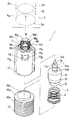
図1と図2は、本実施の形態に係る埋設式サーモスタット1を内燃機関内に設置した状態を示す縦断面図であり、図1は、流路領域を遮断している状態を示し、図2は、流路領域を連通している状態を示す。また、図3と図4は、本実施の形態に係る埋設式サーモスタット1を分解した状態を示しており、図3は斜視図、図4は縦断面図である。なお、この図3及び図4は、前記図1、図2のラジエータ側から埋設式サーモスタット1を見ており、さらにこの分解して示す埋設式サーモスタット1の上方には、埋設式サーモスタット1が嵌め込まれる下部嵌合穴5a等が示されている。
【0011】
埋設式サーモスタット1は、エンジンヘッド2の冷却液流路3を横切って形成される嵌合穴に埋設配置されており、この嵌合穴のうち、冷却液流路3の上側面4の上方に位置する部分が上部嵌合穴4aであり、下側面5の下方に位置する部分が下部嵌合穴5aである。このように配置された埋設式サーモスタット1が、冷却液流路3を流れる冷却液の温度変化に応じて冷却液流路3内の冷却液の流れを制御する。
【0012】
この埋設式サーモスタット1は、中空筒形状のバルブ本体17と、このバルブ本体17内に収装されたサーモバルブ7を備える。バルブ本体17の周面17eには、入口開口部17aと出口開口部17bが対向位置に穿設形成されており、この入口開口部17aと出口開口部17bとを連通する領域が、冷却液の流路となる流路領域FAである。つまり、この入口開口部17aと出口開口部17bの面積を冷却液流路3の断面積に対応させることにより、冷却液の流量を確保する。
【0013】
一方、サーモバルブ7は、ピストン部及び付勢部の作用によってバルブ本体17内を摺動する。サーモバルブ7が、図1の如く進行している状態(本実施の形態では、バルブ本体17内の上部に位置している状態)では、エレメント10の外周面12が、入口開口部17aと出口開口部17bを塞ぎ、流路領域FAを遮断する。また、図2の如く後退している状態(本実施の形態では、バルブ本体17内の下部に位置している状態)では、エレメント10の外周面12による干渉が解かれ、流路領域FAが連通する。つまり、本実施の形態では、サーモバルブ7が、流路領域FAを横断すべく進退動し、この流路領域FAの遮断、連通を行う。以下、埋設式サーモスタット1を形成する各部位について詳述する。
【0014】
[バルブ本体17]
バルブ本体17は、エンジンヘッド2に形成される上部嵌合穴4aと下部嵌合穴5aに挿入可能な外径からなる中空筒形状の部材である。また、このバルブ本体17の上下両端は開放しているが、上端は絞られて端部外周面17fが形成されており、この端部外周面17fにキャップ部材18が固着される(図1から図3参照)。バルブ本体17の周面17eには冷却液の入口開口部17aと出口開口部17bが穿設形成されている。そして、バルブ本体17内に収装されたエレメント10が下降摺動してこれら入口開口部17aと出口開口部17bを開放して流路領域FAを連通すると、冷却液流路3内の冷却液が、ラジエータ側よりエンジン側に流れる。
【0015】
上側面4側の上部嵌合穴4aに挿入されるバルブ本体17の端部外周面17fは、上部嵌合穴4aの段付壁面4bの形状に係合すべく形成され、後述するキャップ部材18が、焼付け等の処理によって固着されている。
なお、バルブ本体17の素材については、設置される環境、即ちエンジンヘッド2からの熱伝導特性及び機械加工特性等を考慮することによって、これらの条件に適合する素材であれば如何なる素材でもよい。
【0016】
バルブ本体17は、図3の如くエンジンヘッド2に形成された下部嵌合穴5aに嵌め込まれる。この下部嵌合穴5aには、開口部2aからバルブ本体17の嵌め込み方向に沿って、かつ、対向する二箇所に位置決め溝2b,2bが形成されている。一方、バルブ本体17の周面17eには、バルブ本体17の軸方向に沿って突起部17g,17gが形成されている。この突起部17g,17gは、位置決め溝2b,2bに摺動可能に係合すべく、位置決め溝2b,2bに対応した形状にて形成されている。
【0017】
[サーモバルブ7]
サーモバルブ7は、バルブ本体17に内装され、主に以下の部材によって形成される。つまり、図1から図3の如く熱膨張体であるワックス15aを内装するワックスケース15と、ワックス15aの膨張収縮を上層の半流動体15cに伝達するダイヤフラム15bと、ダイヤフラム15bの応動を上層のラバーピストン15dに伝達する半流動体15cと、半流動体15cの応動を上層のピストン16に伝達するバックアッププレート15eと、キャップ部材18の金具18aを押圧するピストン16と、これらの構成部位を積層状に内装するエレメント10である。
【0018】
エレメント10には、バルブ本体17の内壁面17cに摺動自在である外周面12が形成されている。この外周面12は、バルブ本体17の内壁面17cに沿って摺動し、その結果、入口開口部17aと出口開口部17bを開閉する。したがって、この外周面12が、流路領域FAを連通、遮断する弁体に相当する。
【0019】
エレメント10の底部側にはワックス15aを内装するワックスケース15がカシメ等の処理により固着されている。一方、この底部側と対峙する上部側には、ピストン16の案内部であるガイド部11が形成されている。このガイド部11の外周面11aは、キャップ部材18の内壁面18hの形状に対応して形成されており、この内壁面18hに対して摺動する。つまり、本実施の形態では、このエレメント10のガイド部11、ピストン16、ワックスケース15、ワックス15a等がピストン部として作用する。
【0020】
ガイド部11の外周面11aには、周面に沿って複数の環状溝部14a,14bが刻設形成されており、キャップ部材18の内壁面18hに複数突設されるリップ部位18e,18fと係合する。その結果、ガイド部11とキャップ部材18の保持がより確実なものとなり、併せて、ガイド部11とピストン16間に生ずる隙間から入ってくる冷却液の侵入を防止する。また、ガイド部11はキャップ部材18によってその外周面11aを保持されているため、ピストン16の伸長に伴って移動するガイド部11の傾きが防止される。
【0021】
[キャップ部材18]
キャップ部材18は、帽子形状に形成されており、頭部部位の外側が、上部嵌合穴4aの中央部に穿設した頭部嵌合穴4cに挿入嵌合する(図1又は図2参照)。そして、このキャップ部材18は、ゴムが焼付け等の処理によって金具18aを包囲し、かつバルブ本体17の端部外周面17fに固着されている(図1から図3参照)。なお、この焼き付け処理等によって一体固着されているバルブ本体17とキャップ部材18の接触面には、互いに係合する溝部17jとリップ部位18iが設けられており、冷却液や塵等の侵入を防止する。
また、キャップ部材18のつば部と外周面にはそれぞれ環状に隆起したリップ部位18b、18c、18dが突設されており、このリップ部18b,18c,18dが上部嵌合穴4aや頭部嵌合穴4cに摺接して冷却液等の侵入を防止する。
【0022】
一方、キャップ部材18の内壁面18hには、リップ部位18e,18fが環状に隆起して突設されており、ガイド部11に形成される環状溝部14a,14bと係合する。したがって、この環状溝部14a,14b、リップ部位18e,18fとの係合により、ガイド部11とピストン16間に生ずる隙間への冷却液の浸入が防止され、併せて、エレメント10が摺動作動する際の傾斜が防止されて安定した作動を可能にする。
【0023】
冷却液流路3の冷却液の温度はエレメント10の外周面12からワックスケース15を介してワックスケース15内のワックス15aに伝達される。この伝達によりワックス15aは膨張若しくは収縮し、ピストン16を進行若しくは後退させようとする。しかし実際には、ピストン16の先端である当接部16aは常に、キャップ部材18の金具18aの当接面18gに接した状態にあり、また、この金具18aは、上部嵌合穴4a内に固定されているため、相対的にエレメント10が押し下げられる。
【0024】
[コイルスプリング6]
サーモバルブ7を付勢するコイルスプリング6が、本実施の形態における付勢部である。このコイルスプリング6は、蓋体19とサーモバルブ7の空隙に介装されており、サーモバルブ7本体を常時、上方方向に付勢するという作用をする(図1から図3参照)。
なお、コイルスプリング6の弾性やコイルスプリング6の全高を変化させることにより、埋設式サーモエレメント1の作動設定温度、流量等の条件を変化させる場合にも、適宜対応させることができる。
【0025】
[蓋体19]
蓋体19の外周面には、雄ねじ部19eが形成されており、一方、エンジンヘッド2に穿設された下部嵌合穴5aの開口部2a側には、この雄ねじ部19eに対応した雌ねじ部2cが形成されている。したがって、この雄ねじ部19eと雌ねじ部2cとの螺合により、蓋体19が固定される。また、下部嵌合穴5aの内部に進入する蓋体19の先端面19aは、バルブ本体17に当接する。したがって、蓋体19をねじ込んでいくと、先端面19aがバルブ本体17の底面17iを押圧し、上部嵌合穴4aや段付壁面4bとの間でバルブ本体17を押圧支持する。
【0026】
さらに、この先端面19aの中央部位には、突出面19bが形成されている。この突出面19bの径は、バルブ本体17の内径に対応して嵌入可能に形成されており、コイルスプリング6を支持する作用をする(図1から図4を参照)。
なお、蓋体19の径d3は、図4の如く下部嵌合穴5aの径d1及び位置決め溝2b,2bの溝深さ寸法(2×d2)を合わせた寸法(d1+2×d2)より大きくなるように形成されており、バルブ本体17と下部嵌合穴5aとの間に生じる隙間から冷却液が漏れ出すのを防止している。
【0027】
続いて、埋設式サーモスタット1の取り付け構造及び具体的な取り付け方法について、説明する。
エンジンヘッド2には、前記した如く、上部嵌合穴4a、下部嵌合穴5a、位置決め溝2a等が形成されている。まず、バルブ本体17を、下部嵌合穴5aに嵌め込む。なお、この嵌め込みに際し、入口開口部17aと出口開口部17bが冷却液流路3と連通するように、向きを合わせて位置合わせする必要がある(図1、図2参照)。この位置合わせにおいて、バルブ本体17の周面17eに形成する突起部17g,17gを、下部嵌合穴5aに形成する位置決め溝2b,2bに嵌め込むと必然的に向き合わせができる。したがって、その後にバルブ本体17を内部に押し込んでも向き合わせにずれが生じず、正確な位置合わせが可能になって取り付けの際の作業性が向上する。また、突起部17g,17gと位置決め溝2a,2aとは嵌合によって係止された状態となるため、バルブ本体17の回転も規制される。
【0028】
このバルブ本体17内には、サーモバルブ7と、コイルスプリング6が内装されており、このバルブ本体17に向けて蓋体19をねじ込む。すると蓋体19の先端面19aが、バルブ本体17の底面17iに当接し、バルブ本体17を押し込む。すると、バルブ本体17は、下部嵌合穴5aの位置決め穴2b,2bに案内されながら移動し、入口開口部17aと出口開口部17bが、冷却液流路3に連通される位置まで達する。
【0029】
本実施の形態に係る埋設式サーモスタット1の作用について説明する(図1、図2参照)。
[埋設式サーモスタット1の閉状態から開状態への作用]
暖機運転前の冷却液流路3内の冷却液は、低温であり、この温度はエレメント10の外周面12とワックスケース15を介してワックスケース15内のワックス15aに伝播する(図1を参照)。
【0030】
時間の経過と共に冷却液流路3内の冷却液の温度は上昇し、ワックスケース15内のワックス15aは膨張して体積が増加し、この体積増加に伴ってダイヤフラム15bが上方へ膨れ上がる。すると、上層の半流動体15cを介して、ラバーピストン15dを上方方向に押し上げようとする力が働く。この力が、バックアッププレート15eを介してピストン16に伝わり、ピストン16がガイド部11から突出しようとする。しかし、ピストン16の先端である当接部16aは、固定されたキャップ部材18における金具18aの当接面18gに常時接触しているため、実際には、エレメント10自体が、ピストン16に対する相対移動によって押し下げられる(図2を参照)。
【0031】
この時、キャップ部材18のリップ部位18eと係合するガイド部11の環状溝部14aは、キャップ部材18の内壁面18hに沿って下降し、最終的にはキャップ部材18のリップ部位18fと係合する。
このリップ部位18fが突出形成される位置は、概ねエレメント10の最下降位置に形成するものであるが、リップ部位18eとリップ部位18fの途中位置に他のリップ部を形成することもできる。この他のリップ部の形成により、ガイド部11とピストン16との隙間部位への冷却液の浸入防止作用を強化することができる。
【0032】
なお、サーモバルブ7と蓋体19との隙間には、サーモバルブ7を常に上方に付勢するためのコイルスプリング6が配置されていて、サーモバルブ7はこのコイルスプリング6の付勢力に抗して下降摺動する。
サーモバルブ7が下降摺動すると、エレメント10の外周面12によって閉状態とされていたバルブ本体17の入口開口部17aと出口開口部17bは開放されて、流路領域FAが連通する。その結果、冷却液が、図2の帯矢印の如くラジエータ側からエンジン側に流れる。
【0033】
[埋設式サーモエレメント1の開状態から閉状態への作用]
エンジンの運転を停止するとウォーターポンプの作動も停止して、冷却液流路3内の冷却液の循環も停止する。時間の経過と共に冷却液の温度は低下するが、この温度変化はエレメント10とワックスケース15を介してワックス15aにも伝播され、温度低下とともに膨張していたワックス15aは収縮する。すると、サーモバルブ7を常に上方に付勢するコイルスプリング6の付勢力によって、サーモバルブ7は上方に摺動する。その結果、エレメント10の外周面12が、最終的にバルブ本体17の入口開口部17aと出口開口部17bを閉状態とし、流路領域FAを遮断する(図1を参照)。
以上が、埋設式サーモスタット1による冷却液流路3の制御作用である。
【0034】
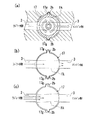
なお、本実施の形態に係る埋設式サーモスタット1では、突起部17g,17gが、バルブ本体17の下端から上端まで連なった状態で形成されている。また、入口開口部17aと出口開口部17bとが形成されたバルブ本体17の周面17eを前後の周面17eと考えた場合、左右に位置する周面17e、つまり、流路領域FAを挟んだ左右の周面17eに突起部17g,17gがそれぞれ形成されている。この形態からなる突起部17g,17gを備えていれば、前記作用に付随して別の作用を奏する。この作用について図5を参照しながら説明する。
【0035】
図5(a)は、図2のX−X断面図であり、同図(b),(c)は、前記作用を説明するための模式図であり、同図(a)を基礎にしている。ちなみに、同図(a)の状態では、流路領域FAは連通状態にあり、帯矢印に示す如く冷却液が流れている。
【0036】
まず、バルブ本体17を下部嵌合穴5aに嵌め込むと、下部嵌合穴5aに形成する位置決め溝2b,2bと、バルブ本体17に形成する突起部17g,17gとの間に若干の隙間が生ずる。すると、同図(b)の点線矢印で示す如く、冷却液が隙間を通って流れる。しかし、実際の取り付けにおいては、蓋体19がバルブ本体17を螺合によって締結するため(図1,図2参照)、バルブ本体17の底面17iには、螺旋方向(回転方向)にモーメントを生じる。その結果、バルブ本体17は回転し、同図(c)の如く、突起部17g,17gが位置決め溝2b,2bに面接触した状態で固定される。すると、前記隙間は塞がれ、この隙間からの冷却液の流出が防止される。
【0037】
このような構造とすることにより、サーモバルブ7が流路領域FAを遮断している場合に、ラジエータ側の冷却液が、エンジン側に漏れてしまう不都合を軽減でき、エンジンの暖機を迅速に行うことが可能になる。
【0038】
次に、本発明に係る埋設式サーモスタットの他の実施の形態(第2の実施の形態)について、図6に沿って説明する。なお、図6は、第2の実施の形態に係る埋設式サーモスタットを取り付けた状態を示す縦断面図である。
図6に示す埋設式サーモスタット1Aも、その基本的な構造については前記の埋設式サーモスタット1と同様であり、前記の埋設式サーモスタット1と同一の部材、同一の作用を奏する部位等については、図面上同じ符号を付し、詳細説明を省略する。
【0039】
図6に示す埋設式サーモスタット1Aは、蓋体19Aに貫通穴19cが形成されており、この貫通穴19cがバイパス通路3Aとバルブ本体17A内とを連通する。バルブ本体17Aは、中空筒形状であるため、この内部を冷却液が流れる。また、バルブ本体17Aの周面17eには、入口開口部17aや出口開口部17b等の他にバイパス開口部17hが穿設形成されている。このバイパス開口部17hは、出口開口部17b側の冷却液流路3に連通しており、サーモバルブ7が流路領域FAを遮断している間は開いている。一方、サーモバルブ7が押し下げられ、流路領域FAを連通すると、エレメント10の外周面12がバイパス開口部17hを閉じる。本実施の形態に係る埋設式サーモスタット1Aを取り付けることで、エンジンルーム内における効率的なレイアウトの達成を一層可能にする。
【0040】
【発明の効果】
本発明によれば、例えば、冷却液流路の管径を太くする等の必要がなくなり、サーモスタットを配置する場所の制限が緩和される。また、位置決め溝及び突起部との嵌合によって、位置合わせ等が容易になり、サーモスタットの取り付けにおける作業性が向上する。さらに、位置決め溝と、バルブ本体に形成する突起部との間の隙間が、蓋体の螺合および蓋体の先端による押圧支持により塞がれる。
【図面の簡単な説明】
【図1】第1の実施の形態に係るサーモスタットを内燃機関内に設置した状態を示す縦断面図であり、流路領域を遮断している状態を示している。
【図2】第1の実施の形態に係るサーモスタットを内燃機関内に設置した状態を示す縦断面図であり、流路領域を連通している状態を示している。
【図3】第1の実施の形態に係るサーモスタットの分解斜視図である。
【図4】第1の実施の形態に係るサーモスタットの分解縦断面図である。
【図5】(a)は図2のX−X断面図であり、(b),(c)は、(a)を基礎にした模式図である。
【図6】第2の実施の形態に係るサーモスタットを内燃機関内に設置した状態を示す縦断面図であり、流路領域を遮断している状態を示している。
【図7】一般的な内燃機関の冷却液流路に従来のサーモスタットを取り付けた状態を示す模式図である。
【図8】図7におけるサーモスタットの取り付け部の拡大図である。
【符号の説明】
1,1A:埋設式サーモスタット(サーモスタット)
2:エンジンヘッド
2a:開口部
2b:位置決め溝
3:冷却液流路
4a,5a:嵌合穴
6:コイルスプリング(付勢部)
7:サーモバルブ
10:エレメント
11:ガイド部(ピストン部の一部)
12:外周面(弁体)
15:ワックスケース(ピストン部の一部)
15a:ワックス(ピストン部の一部)
16:ピストン(ピストン部の一部)
17,17A:バルブ本体
17a:入口開口部
17b:出口開口部
17e:周面
17g:突起部
19,19A:蓋体
FA:流路領域[0001]
TECHNICAL FIELD OF THE INVENTION
The present invention relates to a thermostat mounting structure that is disposed in an internal combustion engine and controls the flow of a coolant by shutting off and communicating between coolant channels.
[0002]
[Prior art]
Most of the cooling systems for internal combustion engines in vehicles currently on the market use a water-cooling system that uses a coolant as a medium to prevent the engine from overheating due to the heat generated by the engine. And keep the engine always at the right temperature.
[0003]
In this water cooling system, a radiator is disposed outside an engine body, and the radiator and the engine body are connected by a rubber hose or the like to circulate a coolant. The main components of this water cooling system are a radiator that plays the role of a heat exchanger, a water pump that forcibly pumps coolant from the engine to the radiator, and a coolant that flows from the radiator or flows to the radiator. The thermostat comprises a thermostat that controls the flow of the cooling liquid at an appropriate temperature by controlling the temperature thereof, and a rubber hose that forms a circulation path for the cooling liquid. The water cooling system used for cooling such an engine is used not only for an engine for a four-wheeled vehicle but also for an engine for a two-wheeled vehicle.
[0004]
A mounting structure of a thermostat arranged in such a water-cooled internal combustion engine will be described with reference to FIGS. FIG. 7 is a schematic diagram showing a state in which a conventional thermostat is attached to a coolant flow passage of a general internal combustion engine, and FIG. 8 is an enlarged view of a mounting portion of the thermostat in FIG.
[0005]
The thermostat 1 'is housed in a case or the like, and is arranged at an appropriate position in a coolant flow path 3' formed between the engine E main body and the radiator R as shown in FIG. As shown in FIG. 8, the thermostat 1 'is provided so that the reciprocating direction of the piston 16' which reciprocates by the action of the element 10 'is parallel to the direction of the flow path of the coolant (see the arrow in FIG. 8). As the piston 16 'moves forward and backward, the valve body 12' and the valve seat 17 'come into contact with or separate from each other, and the coolant flow path is cut off and communicated. In FIG. 8, reference numeral 11 'denotes a guide for guiding the piston 16' forward and backward, reference numeral 15 'denotes a wax case containing wax, and reference numeral 20' denotes a
[0006]
As shown in FIG. 7 (a), the thermostat 1 'closes the coolant passage 3' from the start of the engine until the inside of the engine E reaches an appropriate temperature. In other words, the coolant from the engine E does not go to the radiator R, but circulates to the engine E through the
[0007]
[Problems to be solved by the invention]
By the way, in the conventional thermostat 1 'arranged in the internal combustion engine, in order to keep the flow rate of the coolant passage 3' at a predetermined amount, the diameter of the coolant passage 3 'in which the thermostat 1' is arranged must be large. I had to. However, increasing the diameter of the coolant flow path 3 'is contrary to the demand for enabling an efficient layout.
In addition, the design of the pipe diameter has many restrictions and is difficult to manufacture, so that there are many restrictions on the place where the thermostat is arranged.
Furthermore, even if an appropriate tube diameter is designed and manufactured, it is difficult to arrange the thermostat 1 'at an appropriate position in the tube, and the workability is poor.
An object of the present invention is to solve the above-mentioned problem, and relates to a thermostat mounting structure that alleviates restrictions imposed when a thermostat is arranged and improves workability when the thermostat is arranged.
[0008]
[Means for Solving the Problems]
As means for solving the above-mentioned problems, the present invention provides an inlet opening and an outlet opening formed on a peripheral surface, and the inlet opening and the outlet opening communicate with a coolant flow passage in an internal combustion engine. By the action of a cylindrical valve body that is fixed, a flow path region that connects the inlet opening and the outlet opening in the valve body, and a piston portion and an urging portion, the temperature of the coolant changes. A thermostat mounting structure including a valve body that moves forward and backward to traverse the flow path area in response to the advance and retreat, and shuts off and communicates with the flow path area, and is formed across the coolant flow path. A fitting hole into which the valve body is fitted; a positioning groove formed on an inner wall of the fitting hole along a fitting direction of the valve body from an opening side of the fitting hole; On the surfaceIn a state where it is connected from the lower end to the upper endIs provided, engages with the positioning groove, and is slidable along the positioning groove.Protrusions andAnd a lid that is screwed into the fitting hole from the opening and presses and supports the valve body at the tip.
By this means, for example, it is not necessary to increase the diameter of the coolant flow path, and the restriction on the place where the thermostat is arranged is eased. In addition, the fitting of the positioning groove and the projection facilitates positioning and the like, and improves workability in attaching the thermostat.Further, the gap between the positioning groove and the projection formed on the valve body is closed by screwing of the lid and pressing support by the tip of the lid.
[0009]
BEST MODE FOR CARRYING OUT THE INVENTION
The present invention will be specifically described based on embodiments with reference to the drawings. The following thermostat described as the first embodiment is an embedded thermostat applied to a coolant flow path of an engine head. However, the arrangement position is not limited to the engine head, and may be, for example, an engine block, a radiator, a branch portion of a bypass passage, or the like within the coolant flow path.
[0010]
1 and 2 are longitudinal sectional views showing a state in which the embedded
[0011]
The buried
[0012]
The embedded
[0013]
On the other hand, the
[0014]
[Valve body 17]
The
[0015]
An end outer
The material of the
[0016]
The
[0017]
[Thermo valve 7]
The
[0018]
The
[0019]
A
[0020]
A plurality of
[0021]
[Cap member 18]
The
Also,
[0022]
On the other hand, on the
[0023]
The temperature of the coolant in the
[0024]
[Coil spring 6]
The
In addition, by changing the elasticity of the
[0025]
[Lid 19]
A
[0026]
Further, a protruding
The diameter d3 of the
[0027]
Subsequently, a mounting structure of the embedded
As described above, the
[0028]
The
[0029]
The operation of the embedded
[Action of the embedded
The coolant in the
[0030]
As the time elapses, the temperature of the coolant in the
[0031]
At this time, the
The position at which the
[0032]
A
When the
[0033]
[Operation of the embedded
When the operation of the engine is stopped, the operation of the water pump also stops, and the circulation of the coolant in the
The control operation of the
[0034]
In the embedded
[0035]
FIG. 5A is a cross-sectional view taken along line XX of FIG. 2, and FIGS. 5B and 5C are schematic views for explaining the above-described operation, based on FIG. I have. Incidentally, in the state shown in FIG. 3A, the flow path area FA is in a communicating state, and the coolant flows as shown by the band arrow.
[0036]
First, when the
[0037]
With such a structure, when the thermo-
[0038]
Next, another embodiment (a second embodiment) of the embedded thermostat according to the present invention will be described with reference to FIG. FIG. 6 is a longitudinal sectional view showing a state where the embedded thermostat according to the second embodiment is attached.
The buried thermostat 1A shown in FIG. 6 also has the same basic structure as that of the buried
[0039]
In the embedded thermostat 1A shown in FIG. 6, a through
[0040]
【The invention's effect】
According to the present invention, for example, it is not necessary to increase the pipe diameter of the coolant flow path, and the restriction on the place where the thermostat is arranged is eased. In addition, the fitting of the positioning groove and the projection facilitates positioning and the like, and improves workability in attaching the thermostat.Further, the gap between the positioning groove and the projection formed on the valve body is closed by screwing of the lid and pressing support by the tip of the lid.
[Brief description of the drawings]
FIG. 1 is a longitudinal sectional view showing a state in which a thermostat according to a first embodiment is installed in an internal combustion engine, and shows a state in which a flow path region is blocked.
FIG. 2 is a vertical cross-sectional view showing a state in which the thermostat according to the first embodiment is installed in an internal combustion engine, and shows a state in which a flow path region is communicated.
FIG. 3 is an exploded perspective view of the thermostat according to the first embodiment.
FIG. 4 is an exploded vertical sectional view of the thermostat according to the first embodiment.
5A is a cross-sectional view taken along line XX of FIG. 2, and FIGS. 5B and 5C are schematic diagrams based on FIG.
FIG. 6 is a longitudinal sectional view showing a state where the thermostat according to the second embodiment is installed in an internal combustion engine, and shows a state in which a flow path region is blocked.
FIG. 7 is a schematic diagram showing a state where a conventional thermostat is attached to a coolant flow passage of a general internal combustion engine.
FIG. 8 is an enlarged view of a mounting portion of the thermostat in FIG. 7;
[Explanation of symbols]
1, 1A: Buried thermostat (thermostat)
2: Engine head
2a: Opening
2b: positioning groove
3: Coolant flow path
4a, 5a: fitting holes
6: Coil spring (biasing part)
7: Thermo valve
10: Element
11: Guide part (part of piston part)
12: Outer surface (valve)
15: Wax case (part of piston part)
15a: Wax (part of piston part)
16: Piston (part of piston part)
17, 17A: Valve body
17a: entrance opening
17b: outlet opening
17e: peripheral surface
17g: protrusion
19, 19A: Lid
FA: Channel area
Claims (1)
前記冷却液流路を横切って形成され、前記バルブ本体が嵌め込まれる嵌合穴と、この嵌合穴の開口部側から前記バルブ本体の嵌め込み方向に沿って前記嵌合穴の内壁に形成された位置決め溝と、前記バルブ本体の周面に下端から上端まで連なった状態で設けられ、前記位置決め溝と係合し、かつ、この位置決め溝に沿って摺動可能な突起部と、開口部から前記嵌合穴に螺合し、先端で前記バルブ本体を押圧支持する蓋体を有することを特徴とするサーモスタットの取り付け構造。A cylindrical valve body having an inlet opening and an outlet opening formed in a peripheral surface thereof, the inlet opening and the outlet opening being fixed at a position communicating with a coolant flow path in the internal combustion engine; Due to the action of the piston portion and the urging portion, the passage portion that connects the opening portion and the outlet opening portion within the valve body moves forward and backward so as to cross the flow passage region in response to a change in the temperature of the coolant. A thermostat mounting structure comprising a valve element that shuts off and communicates with the flow path region by the reciprocation.
A fitting hole formed across the coolant flow passage and into which the valve body is fitted, and formed on the inner wall of the fitting hole along the fitting direction of the valve body from the opening side of the fitting hole. a positioning groove, the provided in a state of continuous from the lower end on the peripheral surface of the valve body to the upper end engaged with the positioning groove, and the slidable projections along the positioning groove, from said opening A mounting structure for a thermostat, comprising a lid screwed into a fitting hole and pressingly supporting the valve body at a tip.
Priority Applications (6)
| Application Number | Priority Date | Filing Date | Title |
|---|---|---|---|
| JP01792399A JP3582055B2 (en) | 1999-01-27 | 1999-01-27 | Mounting structure of thermostat |
| CN00101603A CN1109808C (en) | 1999-01-27 | 2000-01-19 | Thermostat mounting structure |
| DE60024340T DE60024340T2 (en) | 1999-01-27 | 2000-01-20 | Component for mounting a thermostat |
| EP00101092A EP1024256B1 (en) | 1999-01-27 | 2000-01-20 | Fitting construction of the thermostat |
| TW089101153A TW429284B (en) | 1999-01-27 | 2000-01-25 | Fitting construction of the thermostat |
| US09/492,447 US6357666B1 (en) | 1999-01-27 | 2000-01-27 | Fitting construction of the thermostat |
Applications Claiming Priority (1)
| Application Number | Priority Date | Filing Date | Title |
|---|---|---|---|
| JP01792399A JP3582055B2 (en) | 1999-01-27 | 1999-01-27 | Mounting structure of thermostat |
Publications (2)
| Publication Number | Publication Date |
|---|---|
| JP2000213353A JP2000213353A (en) | 2000-08-02 |
| JP3582055B2 true JP3582055B2 (en) | 2004-10-27 |
Family
ID=11957301
Family Applications (1)
| Application Number | Title | Priority Date | Filing Date |
|---|---|---|---|
| JP01792399A Expired - Fee Related JP3582055B2 (en) | 1999-01-27 | 1999-01-27 | Mounting structure of thermostat |
Country Status (6)
| Country | Link |
|---|---|
| US (1) | US6357666B1 (en) |
| EP (1) | EP1024256B1 (en) |
| JP (1) | JP3582055B2 (en) |
| CN (1) | CN1109808C (en) |
| DE (1) | DE60024340T2 (en) |
| TW (1) | TW429284B (en) |
Families Citing this family (10)
| Publication number | Priority date | Publication date | Assignee | Title |
|---|---|---|---|---|
| JP3819681B2 (en) * | 2000-07-03 | 2006-09-13 | 本田技研工業株式会社 | Water cooling engine cooling system |
| JP4368043B2 (en) * | 2000-07-25 | 2009-11-18 | 日本サーモスタット株式会社 | Thermostat mounting structure using seal member |
| JP4212388B2 (en) * | 2003-03-11 | 2009-01-21 | 本田技研工業株式会社 | Thermostat mounting structure |
| GB0310122D0 (en) * | 2003-05-02 | 2003-06-04 | Ford Global Tech Llc | Temperature responsive flow control valves for engine cooling systems |
| GB0310120D0 (en) | 2003-05-02 | 2003-06-04 | Ford Global Tech Llc | Engine cooling systems |
| CN100458251C (en) * | 2004-11-18 | 2009-02-04 | 日本恒温装置株式会社 | Thermostatic device |
| US8857480B2 (en) * | 2011-01-13 | 2014-10-14 | GM Global Technology Operations LLC | System and method for filling a plurality of isolated vehicle fluid circuits through a common fluid fill port |
| US9772632B1 (en) * | 2013-11-25 | 2017-09-26 | Richard Michael Ihns | Bypass valve |
| US20190195375A1 (en) * | 2017-12-21 | 2019-06-27 | Caltherm Corporation | Cartridge assembly for a thermally responsive by-pass valve |
| KR102662355B1 (en) * | 2021-05-25 | 2024-05-02 | 박근식 | Samrt hybrid cool or heating water distribution device |
Family Cites Families (9)
| Publication number | Priority date | Publication date | Assignee | Title |
|---|---|---|---|---|
| US3168900A (en) * | 1962-03-23 | 1965-02-09 | Crane Co | Ball valve with flexible bonnet |
| US4605036A (en) * | 1977-06-22 | 1986-08-12 | Xomox Corporation | Valve housing with removable self-contained valving unit |
| US4288033A (en) * | 1978-07-17 | 1981-09-08 | Century Brass Products, Inc. | Control valve assembly |
| US4245781A (en) * | 1979-03-28 | 1981-01-20 | Robertshaw Controls Company | Engine cooling system thermostat and method of making the same |
| DD265662A1 (en) * | 1987-11-02 | 1989-03-08 | Ifa Motorenwerke | DEVICE FOR REGULATING THE LUBRICATION OF THE LUBRICANTS IN HEAT EXCHANGE |
| US4890790A (en) * | 1988-10-03 | 1990-01-02 | Robertshaw Controls Company | Engine cooling system, structure therefor and methods of making the same |
| US5123591A (en) * | 1991-02-15 | 1992-06-23 | Reynolds William J | Radiator hose with internally mounted thermostat |
| US5681028A (en) * | 1995-10-23 | 1997-10-28 | Emhart Inc. | Valve assembly |
| US5881757A (en) * | 1997-05-02 | 1999-03-16 | Senninger Irrigation, Inc. | Pressure regulator apparatus and method |
-
1999
- 1999-01-27 JP JP01792399A patent/JP3582055B2/en not_active Expired - Fee Related
-
2000
- 2000-01-19 CN CN00101603A patent/CN1109808C/en not_active Expired - Fee Related
- 2000-01-20 EP EP00101092A patent/EP1024256B1/en not_active Expired - Lifetime
- 2000-01-20 DE DE60024340T patent/DE60024340T2/en not_active Expired - Fee Related
- 2000-01-25 TW TW089101153A patent/TW429284B/en not_active IP Right Cessation
- 2000-01-27 US US09/492,447 patent/US6357666B1/en not_active Expired - Fee Related
Also Published As
| Publication number | Publication date |
|---|---|
| US6357666B1 (en) | 2002-03-19 |
| DE60024340T2 (en) | 2006-08-24 |
| CN1262383A (en) | 2000-08-09 |
| DE60024340D1 (en) | 2006-01-05 |
| EP1024256A3 (en) | 2002-05-15 |
| TW429284B (en) | 2001-04-11 |
| EP1024256A2 (en) | 2000-08-02 |
| EP1024256B1 (en) | 2005-11-30 |
| JP2000213353A (en) | 2000-08-02 |
| CN1109808C (en) | 2003-05-28 |
Similar Documents
| Publication | Publication Date | Title |
|---|---|---|
| JP4262346B2 (en) | thermostat | |
| KR100685213B1 (en) | Method for controlling flow of cooling medium | |
| JP3582055B2 (en) | Mounting structure of thermostat | |
| US7082903B2 (en) | Temperature responsive flow control valves for engine cooling systems | |
| AU2007228293A1 (en) | Thermostat apparatus | |
| JP2006342767A (en) | Thermostat unit | |
| US20050001044A1 (en) | Thermostat for two-system cooling device | |
| JP2007291928A (en) | Engine cooling system | |
| JP4368043B2 (en) | Thermostat mounting structure using seal member | |
| JP4558901B2 (en) | Thermostat and mounting structure of thermostat | |
| CN110630729B (en) | Temperature regulating valve | |
| JP2932348B2 (en) | thermostat | |
| JP4408539B2 (en) | Thermostat case structure | |
| KR100435946B1 (en) | Cooling system for engine | |
| JP2007291927A (en) | Engine cooling system | |
| EP1219879B1 (en) | Case structure of thermostat | |
| WO2019066758A1 (en) | A thermostat assembly with an improved bypass control | |
| JP7393370B2 (en) | thermostat device | |
| JP2005127361A (en) | Thermostat device | |
| KR20040049080A (en) | Oil cooler for a diesel engine |
Legal Events
| Date | Code | Title | Description |
|---|---|---|---|
| A977 | Report on retrieval |
Free format text: JAPANESE INTERMEDIATE CODE: A971007 Effective date: 20040319 |
|
| A131 | Notification of reasons for refusal |
Free format text: JAPANESE INTERMEDIATE CODE: A131 Effective date: 20040414 |
|
| A521 | Request for written amendment filed |
Free format text: JAPANESE INTERMEDIATE CODE: A523 Effective date: 20040610 |
|
| TRDD | Decision of grant or rejection written | ||
| A01 | Written decision to grant a patent or to grant a registration (utility model) |
Free format text: JAPANESE INTERMEDIATE CODE: A01 Effective date: 20040707 |
|
| A61 | First payment of annual fees (during grant procedure) |
Free format text: JAPANESE INTERMEDIATE CODE: A61 Effective date: 20040716 |
|
| R150 | Certificate of patent or registration of utility model |
Free format text: JAPANESE INTERMEDIATE CODE: R150 |
|
| FPAY | Renewal fee payment (event date is renewal date of database) |
Free format text: PAYMENT UNTIL: 20080806 Year of fee payment: 4 |
|
| FPAY | Renewal fee payment (event date is renewal date of database) |
Free format text: PAYMENT UNTIL: 20090806 Year of fee payment: 5 |
|
| FPAY | Renewal fee payment (event date is renewal date of database) |
Free format text: PAYMENT UNTIL: 20090806 Year of fee payment: 5 |
|
| FPAY | Renewal fee payment (event date is renewal date of database) |
Free format text: PAYMENT UNTIL: 20100806 Year of fee payment: 6 |
|
| FPAY | Renewal fee payment (event date is renewal date of database) |
Free format text: PAYMENT UNTIL: 20110806 Year of fee payment: 7 |
|
| FPAY | Renewal fee payment (event date is renewal date of database) |
Free format text: PAYMENT UNTIL: 20110806 Year of fee payment: 7 |
|
| FPAY | Renewal fee payment (event date is renewal date of database) |
Free format text: PAYMENT UNTIL: 20120806 Year of fee payment: 8 |
|
| FPAY | Renewal fee payment (event date is renewal date of database) |
Free format text: PAYMENT UNTIL: 20120806 Year of fee payment: 8 |
|
| FPAY | Renewal fee payment (event date is renewal date of database) |
Free format text: PAYMENT UNTIL: 20120806 Year of fee payment: 8 |
|
| FPAY | Renewal fee payment (event date is renewal date of database) |
Free format text: PAYMENT UNTIL: 20130806 Year of fee payment: 9 |
|
| LAPS | Cancellation because of no payment of annual fees |