CN1199018C - Case structure of thermostat - Google Patents
Case structure of thermostat Download PDFInfo
- Publication number
- CN1199018C CN1199018C CN 01802162 CN01802162A CN1199018C CN 1199018 C CN1199018 C CN 1199018C CN 01802162 CN01802162 CN 01802162 CN 01802162 A CN01802162 A CN 01802162A CN 1199018 C CN1199018 C CN 1199018C
- Authority
- CN
- China
- Prior art keywords
- mentioned
- thermostat
- shell
- opening portion
- stream
- Prior art date
- Legal status (The legal status is an assumption and is not a legal conclusion. Google has not performed a legal analysis and makes no representation as to the accuracy of the status listed.)
- Expired - Fee Related
Links
Images


Classifications
-
- F—MECHANICAL ENGINEERING; LIGHTING; HEATING; WEAPONS; BLASTING
- F01—MACHINES OR ENGINES IN GENERAL; ENGINE PLANTS IN GENERAL; STEAM ENGINES
- F01P—COOLING OF MACHINES OR ENGINES IN GENERAL; COOLING OF INTERNAL-COMBUSTION ENGINES
- F01P7/00—Controlling of coolant flow
- F01P7/14—Controlling of coolant flow the coolant being liquid
- F01P7/16—Controlling of coolant flow the coolant being liquid by thermostatic control
-
- F—MECHANICAL ENGINEERING; LIGHTING; HEATING; WEAPONS; BLASTING
- F01—MACHINES OR ENGINES IN GENERAL; ENGINE PLANTS IN GENERAL; STEAM ENGINES
- F01P—COOLING OF MACHINES OR ENGINES IN GENERAL; COOLING OF INTERNAL-COMBUSTION ENGINES
- F01P2070/00—Details
Landscapes
- Engineering & Computer Science (AREA)
- Chemical & Material Sciences (AREA)
- Combustion & Propulsion (AREA)
- Mechanical Engineering (AREA)
- General Engineering & Computer Science (AREA)
- Temperature-Responsive Valves (AREA)
- Cooling, Air Intake And Gas Exhaust, And Fuel Tank Arrangements In Propulsion Units (AREA)
- Measuring Temperature Or Quantity Of Heat (AREA)
Abstract
To provide a case structure for a thermostat allowing efficient layout of a coolant flow passage by burying the thermostat into a member to be mounted such as an engine head, an easy mounting work of the thermostat, an effective use of a case of the thermostat and easy mounting of a liquid temperature sensor and a jiggle valve. In the case structure comprising a cylindrical case 1 with an inlet opening part and an outlet opening part formed on a peripheral surface, a flow passage area for communicating the inlet opening part 1a and the outlet opening part 1b within the case 1 and a valve element 2 advancing/retreating so as to cross the flow passage area according to a temperature change in coolant flowing in the flow passage area and interrupting and communicating the flow passage area by the advancing/retreating and being buried into a fitting hole of the member to be mounted with a formed coolant flow passage, a through hole 1d is formed in the case 1.
Description
Technical field
The present invention relates to the shell mechanism of thermostat, this thermostat be configured in the internal-combustion engine, by cutting off, being communicated with the cooling liquid stream, the mobile of cooling liquid controlled.The present invention is especially with the sort of to effectively utilize the thermostat shell mechanism that constitutes the thermostat shell relevant.
Background technique
Now commercially available vehicle is to adopt the water-cooling pattern of cooling liquid as medium cooled off motor with internal-combustion engine cooling system mostly, the cooling system of this water-cooling pattern also is widely used for two-wheel vehicle used motor except that the motor that the supply four-wheel wagon is used.
The vehicle internal-combustion engine cooling system of above-mentioned employing water-cooling pattern be with heat sink arrangements on the outside of engine body, with rubber hose etc. this radiator is connected with engine body and makes the system of liquid circulation; It is by constituting with the bottom: the radiator that plays the heat exchanger effect; Force good general's cooling liquid to be sent to the water pump of above-mentioned radiator from motor; That control comes from radiator stream or to the flowing of the cooling liquid of radiator diffluence, to keep the thermostat of proper temperature; Form the rubber hose of liquid circulation stream etc.
The function of above-mentioned cooling system is prevent to be caused by motor heating overheated, prevents the cold excessively of cold period on the other hand, thus motor is remained at proper temperature.
Below, with reference to Figure 10 and Figure 11 general thermostat and the mounting structure of thermostat that is used for this water-cooling pattern is described.Figure 10 is illustrated in the view that former thermostat is installed on the cooling liquid of IC engine stream, and Figure 11 is a schematic representation of representing the thermostat assembly department among Figure 10 enlargedly.
As shown in figure 10, thermostat 100 is configured on the assigned position of the cooling liquid stream 110 that forms between motor E body and the radiator R.As shown in figure 11, the mobile piston 102 of advancing and retreat by the effect of parts 101 is being set on this thermostat 100, above-mentioned thermostat 100 is configured to make its advance and retreat direction of piston 102 parallel with the path direction of cooling liquid on cooling liquid stream 110.
And, in above-mentioned thermostat 100, move by the advance and retreat of above-mentioned piston 102 and valve body 103 to be engaged with valve seat 104 or separate, carry out the cut-out or the connection of cooling liquid stream thus.
Below, the action of above-mentioned thermostat 100 is described.Shown in Figure 10 (a), begin during from engine start in motor E, to reach till the proper temperature during this period of time, thermostat 100 cuts out cooling liquid stream 110.
Promptly, because the cooling liquid that flows out from motor E does not flow to radiator R, towards motor E circulation (seeing the arrow among Figure 10 (a)), thereby make it reach suitable temperature in advance by bypass path 110A.
On the other hand, in motor E, reach proper temperature after, shown in Figure 10 (b), the valve body of thermostat 100 103 is opened, and the cooling liquid stream 110 of radiator R one side is opened.The result makes cooling liquid pass through to circulate (with reference to the arrow among Figure 10 (b)) towards motor E behind the radiator R, with cooling off in the motor E, holds it in proper temperature thus.
But, because the thermostat before above-mentioned is arranged on cooling liquid stream inside, thereby, just the caliber that disposes the cooling liquid stream of thermostat must be strengthened for the flow with the cooling liquid stream is held in established amount, its result just makes the caliber of cooling liquid stream increase, and can not carry out high efficiency layout.And also there is more restriction at the position of configuration thermostat, and the installation exercise of thermostat is also very difficult.
In order to address these problems, report the scheme that once proposed to have proposed to bury underground the formula thermostat in flat 11-17923 number in Japanese Patent Application Publication, this thermostat is arranged on the cooling liquid stream of crosscut engine head and in the embedding hole that forms (special be willing to flat 11-17923 number) with burying underground.
Also having a kind of scheme is in the former cooling system of vehicle with internal-combustion engine liquid temperature sensor to be set, and when the temperature of cooling liquid surpasses the temperature of regulation, the electronic cooling fan that is arranged in the radiator is driven.This liquid temperature sensor and thermostat are provided with respectively.
For this reason, the position that is provided with of liquid temperature sensor must be guaranteed to be used to be provided with, and its installation exercise must be carried out.
And, when cooling liquid being injected in radiator, the cooling jacket, must carry out so-called exhaust.With in the cooling system of internal-combustion engine, in order to carry out exhaust, all is that so-called inching valve (jiggle valve) is set so far at vehicle, and still, this inching valve is also the same with liquid temperature sensor, must guarantee to be provided with the position, also must carry out its installation exercise.
Disclosure of an invention
The present invention makes for the problem that solves above-mentioned prior art existence, its objective is the shell mechanism that a kind of thermostat is provided, be mounted in the parts by thermostat being embedded to engine head etc., can carry out the layout of cooling liquid stream expeditiously, and the installation exercise of thermostat is also easy, can also effectively utilize the shell of thermostat, parts such as liquid temperature sensor, inching valve are installed easily.
The shell mechanism of the thermostat of the present invention of making in order to address the above problem is for to have: the shell cylindraceous that forms inlet opening portion and exit opening portion on side face; The stream zone that in above-mentioned shell, above-mentioned inlet opening portion and exit opening portion is communicated with; Carry out the advance and retreat action in cross-section above-mentioned stream zone, move the valve body in cut-out, the above-mentioned stream of connection zone by this advance and retreat according to the temperature of the cooling liquid that flows through above-mentioned stream zone, and be embedded in the embedding hole that is mounted parts that is formed with the cooling liquid stream, it is characterized in that
On the sidewall of above-mentioned shell, be formed with through hole, in above-mentioned through hole, insert the connecting line that is installed in the electronic component on the thermostat.
Owing on the shell of thermostat, be formed with through hole, thereby parts such as liquid temperature sensor, inching valve can be installed on the thermostat, liquid temperature sensor, inching valve etc. can be installed when being installed in thermostat on the cooling system.Because thermostat is embedded in the embedding hole that is mounted parts that forms the cooling liquid stream, thereby thermostat can easily be installed, and can carry out layout expeditiously.
Best, above-mentioned shell has: the cap cylindraceous portion that forms highlightedly from above-mentioned shell upper-end surface, the joint that connects above-mentioned shell upper-end surface and cap portion; Above-mentioned through hole is formed in side wall of outer shell cylindraceous, cap portion, the joint on any one.
Like this, owing to will be installed in the electronic component on the thermostat, the connecting line that for example detects the liquid temperature sensor of coolant temperature or heat the such electronic components such as electronic component of PTC, the kuromore heater of wax case is forcibly inserted and is led in through hole, thereby, by being installed in, thermostat is mounted the installation and the distribution that just can carry out electronic component on the parts simultaneously.
Best, inching valve with inching valve spheroid folding and unfolding portion of the above-mentioned inching valve spheroid of inching valve spheroid and folding and unfolding is arranged in the through hole of above-mentioned shell, and above-mentioned inching valve has the fine motion pin that valve body and above-mentioned valve body form on its two ends inching valve is to install by the fine motion pin is inserted in the through hole that feeds above-mentioned shell.
Like this, owing in the through hole of shell, be provided with so-called inching valve, thereby just inching valve can be installed simultaneously by thermostat is installed.
The simple declaration of accompanying drawing
Fig. 1 is the plan view of the formula of burying underground the thermostat of the 1st mode of execution.
Fig. 2 is the front view of the formula of burying underground thermostat shown in Figure 1.
Fig. 3 is the side view of the formula of burying underground thermostat shown in Figure 1.
Fig. 4 is the profile diagram of the formula of burying underground thermostat shown in Figure 1.
Fig. 5 is the expression profile diagram that will bury the formula thermostat underground and be arranged on the state in the internal-combustion engine, is the schematic representation that the state in stream zone is cut off in expression.
Fig. 6 is the expression profile diagram that will bury the formula thermostat underground and be arranged on the state in the internal-combustion engine, is the schematic representation that expression is communicated with the state in stream zone.
Fig. 7 is the profile diagram of the thermostat of the 2nd mode of execution.
Fig. 8 is the schematic representation of the thermostat of expression the 3rd mode of execution.
Fig. 9 is the schematic representation of the thermostat of expression the 4th mode of execution.
Figure 10 is the view that former thermostat is installed on the general cooling liquid of IC engine stream of expression.
Figure 11 is the enlarged view of the thermostat assembly department among Figure 10.
The optimal way that carries out an invention
Below, with reference to Fig. 1~Fig. 6 the 1st mode of execution of the present invention is described.
This formula thermostat A that buries underground is made of following parts, promptly, shell 1; Be installed in the thermoinduction valve (thermo valve) 2 in the shell 1; By the thermoelectric element 10 that above-mentioned thermoinduction valve 2 heating is made forcibly its action; With as the motor B threaded joint that is mounted parts and with the lid 3 of the bottom surface obturation of shell 1; Be installed between thermoinduction valve 2 and the lid 3, with the helical spring 4 that pushes away on the thermoinduction valve 2.
Above-mentioned shell 1 has hollow tube-shape, as Fig. 5, shown in Figure 6, goes up the cooling liquid stream 3 that forms with engine head B and forms inlet opening portion 1a and the 1b of exit opening portion accordingly.And, form through hole 1d in the lower portion of the inlet opening portion 1a of side face (sidewall) 1c of above-mentioned shell 1, be used to make the connecting line 10a that is connected with thermoelectric element 10 to be drawn out to the outside of side face (sidewall) 1c of shell 1.
Lower portion at the 1b of exit opening portion of side face (sidewall) 1c of above-mentioned shell 1 forms the 1f of exit opening portion that bypass path is used, and on the other hand, forms the inlet opening portion 1e that bypass path is used in the bottom surface of shell 1.As shown in Figure 5, the inlet opening portion 1e that uses of above-mentioned bypass path and the 1f of exit opening portion make at will enter the mouth opening portion 1a, the 1b of exit opening portion of parts (valve body) 2a can be interconnected when inaccessible.Also chimeric metal annulus 5 on the recess 1g of the underpart of shell 1 inwall is in order to support helical spring 4.
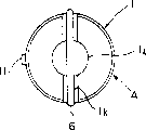
On the 1h of the top of above-mentioned shell 1, be integrally formed into the 1i of cap portion with shell 1, it be with side face (sidewall) the 1c concentric circles of shell 1 and diameter less than side face (sidewall) 1c.On the 1h of the top of shell 1, also be provided with and connect above the shell 1 and the joint 1j of the 1i of cap portion.As shown in Figure 2, joint 1j is arranged on the neutral position of inlet opening portion 1a and the 1b of exit opening portion.Promptly, make the structure that the side 1b of exit opening portion and inlet opening portion side 1a are separated.
And, go up the groove 1k that forms the straight line shape that above-mentioned three is linked to each other at the upper-end surface 1i1 of ridge edge portion 1j1, the 1i of cap portion of side face (sidewall) 1c, the joint 1j of above-mentioned shell 1, chimeric circular rubber components 6 in above-mentioned groove 1k.On the bottom of shell 1, also form groove 1k, make and do not make circular rubber components 6 outstanding egregiously.
Also be provided with the jut 11 of location usefulness at the lower direction position (underpart) of the inlet opening portion 1a of the cooling liquid stream 3 of above-mentioned shell 1.With this jut 11 accordingly, on the sidewall in chimeric cave 7 set on the engine head B, be provided with recess 7a, above-mentioned jut 11 cards end in recess 7a.And, by sealed member 8, by the bottom surface obturation of the lid 3 that forms bypass 3a with above-mentioned shell 1.
Below, explain thermoinduction valve 2, this thermoinduction valve 2 is made of following parts, promptly, inside is equipped with wax case 2c as the wax 2b of expander, the barrier film 2e of semifluid 2d that expansion or the contraction of wax 2b is communicated to the upper strata, with barrier film 2e corresponding move the rubber piston 2f that passes to the upper strata semifluid 2d, semifluid 2d corresponding moved the support plate 2h of the piston 2g that passes to the upper strata, piston 2g that cap is pushed, inner laminated parts (valve body) 2a that these formation positions are installed is being set.And above-mentioned parts (valve body) 2a makes and can freely slide along the internal face 1m of shell 1, the structure that can open and close inlet opening portion 1a and the 1b of exit opening portion thus.
On the bottom surface of above-mentioned thermoinduction valve 2 (wax case 2c), be provided with thermoelectric element 10, by to the heating of wax 2c, forcibly above-mentioned wax 2b is expanded.Connecting the connecting line 10a that is used to connect power supply on this thermoelectric element 10, this connecting line 10a is directed into the outside of shell 1 as described above via through hole 1d.The thermoelectric element here is meant for example PTC, the such heating element of kuromore heater.
The upper side with bottom side stands facing each other mutually of wax case 2c forms guide portion 2c1, and it is the guide portion of piston 2g.The peripheral part of this guide portion 2c1 is made corresponding with the shape of the internal face 1n of cap portion, can slide with respect to this internal face 1n.
Above-mentioned helical spring 4 is contained in the space between annulus 5 and the thermoinduction valve 2, makes thermoinduction valve 2 bodies depend on (with reference to Fig. 4, Fig. 5) all the time upward.Under the occasion that conditions such as even the height overall at elasticity that makes helical spring 4 and helical spring 4 changes, make the action setting temperature that buries formula thermostat A thus, flow change, also can be suitably corresponding with it.
On above-mentioned lid 3, form the screw section that does not have expression among the figure, by with the threaded joint of engine head 8, via sealed member 8 that lid 3 is fixing.
Below, the installation method of thermostat A is described.
First assembling thermostat A is directed to the outside by the through hole 1a of shell 1 with the connecting line 10a of thermoelectric element 10.And, on engine head B, form chimeric cave 9, top and chimeric cave 7, bottom in advance.
Then thermostat A shell 1 is embedded in chimeric cave 9, above-mentioned top, the chimeric cave 7, bottom.Carrying out when chimeric, must carry out towards the location that coincide inlet opening portion 1a and the 1b of exit opening portion, make they be connected with cooling liquid stream 3 (referring to Fig. 5 and Fig. 6).Then, under the state in shell 1 being fitted to chimeric cave 7,9, via sealed member 8 with lid 3 and engine head B threaded joint, thus with the bottom surface obturation of shell 1.
At this moment, the connecting line 10a of above-mentioned thermoelectric element 10 is drawn out to the outside of shell 1 via the through hole 1d of shell 1, by the gap between above-mentioned chimeric cave 7 and the shell 1, draw from chimeric cave 7.And, be drawn out to the outside via the through hole of through hole that on sealed member 8, forms and lid 3, be connected with power supply.Like this, when thermostat is installed, thermoelectric element 10 has been installed also.And need not guarantee to be used to install the space of thermoelectric element 10, the restriction that is not provided with.
Under shell 1 is assembled into state on the engine head B, because above-mentioned rubber components 6 and chimeric cave 9, top, chimeric cave, bottom 7 fluid-tight engagement, thereby the gap that cooling liquid can be along the chimeric cave 9 of side face 1c and top of shell 1, between the chimeric cave 7, bottom and sewing.
Below, the effect of the thermostat A of present embodiment is described with reference to Fig. 2, Fig. 3.
The effect of explanation earlier from the closed condition of thermostat A towards opening state.Before warm-operation, the cooling liquid in the cooling liquid stream 3 is in low temperature, and this temperature is passed to the interior wax 2b (with reference to Fig. 5) of wax case 2c via outer circumferential face and the wax case 2c of parts (valve body) 2a.
Then, when As time goes on, when the coolant temperatures in the cooling liquid stream 3 rose, the wax 2b in the wax case 2c expanded, and volume increases; Along with the increase of this volume, barrier film 2e heaves upward.Consequently produce the power of rubber piston 2f being pushed to the top via the semifluid 2d on upper strata.This power is passed to piston 2g via support plate 2h, makes piston 2g outstanding from guide portion 2c1.But, because the front end of piston 2g contacts with fastening cap portion all the time, thus be actually parts (valve body) 2a from when overcoming the reaction force of helical spring 4 by being pushed down with respect to relatively moving of piston 2g.
Then, when thermoinduction valve 2 descends slip, open, make the FA circulation of stream zone because the outer circumferential face of parts (valve body) 2a will be in the inlet opening portion 1a and the 1b of exit opening portion of the shell 1 of closed condition.Its result makes cooling liquid shown in the arrow among Fig. 6, from radiator one effluent to motor one side.
For with the liquid temperature of cooling liquid irrespectively, be transformed into opening state from closed condition forcibly, from connecting line 10a supply capability, by thermoelectric element 10 heating wax case 2c, wax 2b is expanded.Its result and above-mentioned action are similarly opened the inlet opening portion 1a and the 1b of exit opening portion of shell 1, and stream zone FA is communicated with.
Below, illustrate that thermostat A's is transformed into the effect of closed condition from opening state.When shutting engine down turned round, the action of water pump stopped, thereby the liquid circulation in the cooling liquid stream 3 stops.As time goes on, the temperature of cooling liquid reduces, and this variation of temperature is passed to wax 2b via parts (valve body) 2a and wax case 2c.So,,, thermoinduction valve 2 is slided upward by the elastic force of the helical spring 4 that thermoinduction valve 2 is depended on all the time upward along with temperature reduces and the wax 2b contraction of expansion.
The result forms by the outer circumferential face of parts (valve body) 2a inlet opening portion 1a and the 1b of the exit opening portion closing state with shell 1, and FA cuts off (with reference to Fig. 5) with the stream zone.
Below, with reference to Fig. 7 the 2nd mode of execution of the present invention is described.
Fig. 7 is thermostat that expression will be buried formula underground the profile diagram when being arranged in the internal-combustion engine, is the state that the stream zone is cut off in expression.
The feature of this mode of execution is to dispose liquid temperature sensor 20 on the inlet opening portion 1a, the connecting line 11a of above-mentioned liquid temperature sensor 20 is drawn out to the outside by the last through hole 1p that forms of the sidewall 1c of shell 1, other structures are identical with the 1st mode of execution, thereby omit the explanation to them.
Above-mentioned through hole 1p is the bottom surface that is formed into shell 1 from inlet opening portion 1a, forms the opening portion of through hole 1p on above-mentioned bottom surface.Therefore.The connecting line 11a that draws from through hole 1p is the sealed member 8 that do not have expression from figure, lid 3 and be drawn out to the outside.
Like this, because the thermostat A that is provided with liquid temperature sensor 20 is arranged in the internal-combustion engine, just liquid temperature sensor 20 and thermostat A can be installed simultaneously.And, the space that also needn't guarantee to be used to install liquid temperature sensor 20, the restriction that is not provided with.
Below, with reference to Fig. 8 the 3rd mode of execution of the present invention is described.
Fig. 8 (a) is the side view of the thermostat of expression the present invention the 3rd mode of execution, and Fig. 8 (b) is the front view of the thermostat of expression the present invention the 3rd mode of execution.
The feature of this mode of execution is that formation through hole 1q is being provided with inching valve 12 on this through hole 1g on the joint 1j of shell 1.Above-mentioned inching valve 12 has the fine motion pin 12c that valve body 12a, 12b, above-mentioned valve body 12a, 12b form on its two ends.And, by above-mentioned fine motion pin 12c being inserted lead in the above-mentioned through hole 1q inching valve 12 is contained on the shell 1.
Because other structures are identical with the 1st mode of execution, thereby omit explanation to them.
Like this, under the state that shell 1 is fitted on the engine head B, inlet opening portion 1a one side and the 1b of exit opening portion one side of the cooling liquid of being separated by outer circumferential face 1c, joint 1j, the 1i of cap portion top (being erected at shell side face, joint, rubber components 6 above the cap portion) are communicated with by above-mentioned through hole 1q, opened, are closed by above-mentioned valve body 12a, 12b (inching valve 12).
When injecting cooling liquid, valve body 12a, 12b (inching valve 12) form the air escape route, because that it and former inching valve play a part is same, thereby omit its detailed description here.
Like this, be arranged in the internal-combustion engine owing to will be provided with the thermostat A of so-called inching valve 12, thereby so-called inching valve 12 and thermostat A can be installed simultaneously.Also needn't guarantee to be used to install the space of inching valve 12, the restriction that is not provided with.
Below, with reference to Fig. 9 the 4th mode of execution of the present invention is described.
Fig. 9 is that expression is arranged on view in the internal-combustion engine with thermostat, and the state in stream zone is cut off in expression.
The feature of this mode of execution is that through hole 1r is formed on sidewall (side face) 1c of shell 1, is provided with inching valve 13 in above-mentioned through hole 1r.Because other structures are identical with the 1st mode of execution, thereby omit explanation to them.
Above-mentioned inching valve 13 is made of inching valve spheroid 13a and inching valve body 13b.The above-mentioned inching valve spheroid of above-mentioned inching valve body 13b folding and unfolding 13a has and has formed the 13c of outer openings portion that closed by above-mentioned inching valve spheroid 13a and the 13e of folding and unfolding portion of inboard opening portion 13d.And above-mentioned inching valve body 13b is entrenched in the through hole 1r on shell 1 sidewall (side face) 1c, is fixed on the shell 1.
Therefore, be at above-mentioned inching valve spheroid 13a and the 13c of outer openings portion, inboard opening portion 13d do not had under the closing state internal communication of above-mentioned folding and unfolding 13e of portion and shell 1.This inching valve spheroid 13a also have with above-mentioned the 3rd mode of execution in the same function of valve body 12a, 12b (inching valve 12), when injecting cooling liquid, form the passage that air is escaped, omit explanation here to this respect.
Like this, be arranged in the internal-combustion engine, just so-called inching valve 13 and thermostat A can be installed simultaneously by the thermostat A that will be provided with so-called inching valve 13.And, the space that needn't guarantee to be used to install inching valve, the restriction that also is not provided with.
Though the illustrated thermostat of above-mentioned mode of execution is the formula of burying underground the thermostat that is applicable to the cooling liquid stream, but, its allocation position but is not limited to engine head, so long as the position in the cooling liquid stream can, for example, can be arranged on the inside of cluster engine, radiator, the branch part of bypass path etc. locates.
As mentioned above, if adopt the shell mechanism of thermostat of the present invention, then be mounted the layout that just can carry out high efficiency cooling liquid stream in the parts, and can easily carry out the installation exercise of thermostat by being embedded to.
In addition, can effectively utilize the shell of thermostat, liquid temperature sensor, inching valve etc. easily are installed, and can side by side be carried out the installation of these parts with the installation of thermostat.
Claims (3)
1. the shell mechanism of a thermostat, this thermostat has: the shell cylindraceous that forms inlet opening portion and exit opening portion on side face; The stream zone that in above-mentioned shell, above-mentioned inlet opening portion and exit opening portion is communicated with; Carry out the advance and retreat action in cross-section above-mentioned stream zone, move the valve body in cut-out, the above-mentioned stream of connection zone by this advance and retreat according to the temperature of the cooling liquid that flows through above-mentioned stream zone, and be embedded in the embedding hole that is mounted parts that is formed with the cooling liquid stream, it is characterized in that
On the sidewall of above-mentioned shell, be formed with through hole, in above-mentioned through hole, insert the connecting line that is installed in the electronic component on the thermostat.
2. the shell mechanism of a thermostat, this thermostat has: the shell cylindraceous that forms inlet opening portion and exit opening portion on side face; The stream zone that in above-mentioned shell, above-mentioned inlet opening portion and exit opening portion is communicated with; Carry out the advance and retreat action in cross-section above-mentioned stream zone, move the valve body in cut-out, the above-mentioned stream of connection zone by this advance and retreat according to the temperature of the cooling liquid that flows through above-mentioned stream zone, and be embedded in the embedding hole that is mounted parts that is formed with the cooling liquid stream, it is characterized in that
Be formed with through hole on the sidewall of above-mentioned shell, the inching valve with inching valve spheroid folding and unfolding portion of the above-mentioned inching valve spheroid of inching valve spheroid and folding and unfolding is arranged in the through hole of above-mentioned shell.
3. the shell mechanism of a thermostat, this thermostat has: the shell cylindraceous that forms inlet opening portion and exit opening portion on side face; The stream zone that in above-mentioned shell, above-mentioned inlet opening portion and exit opening portion is communicated with; Carry out the advance and retreat action in cross-section above-mentioned stream zone, move the valve body in cut-out, the above-mentioned stream of connection zone by this advance and retreat according to the temperature of the cooling liquid that flows through above-mentioned stream zone, and be embedded in the embedding hole that is mounted parts that is formed with the cooling liquid stream, it is characterized in that
Above-mentioned shell has: the cylindric cap portion that forms highlightedly from above-mentioned shell upper-end surface, the joint that connects above-mentioned shell upper-end surface and cap portion,
Form through hole on above-mentioned joint, having the inching valve that valve body and above-mentioned valve body be formed on the fine motion pin on its two ends is by installing in the through hole that above-mentioned fine motion pin is inserted above-mentioned shell.
Applications Claiming Priority (3)
| Application Number | Priority Date | Filing Date | Title |
|---|---|---|---|
| JP2000223311A JP4408539B2 (en) | 2000-07-25 | 2000-07-25 | Thermostat case structure |
| JP22331/00 | 2000-07-25 | ||
| JP223311/2000 | 2000-07-25 |
Publications (2)
| Publication Number | Publication Date |
|---|---|
| CN1386178A CN1386178A (en) | 2002-12-18 |
| CN1199018C true CN1199018C (en) | 2005-04-27 |
Family
ID=18717424
Family Applications (1)
| Application Number | Title | Priority Date | Filing Date |
|---|---|---|---|
| CN 01802162 Expired - Fee Related CN1199018C (en) | 2000-07-25 | 2001-07-09 | Case structure of thermostat |
Country Status (3)
| Country | Link |
|---|---|
| JP (1) | JP4408539B2 (en) |
| CN (1) | CN1199018C (en) |
| TW (1) | TW482858B (en) |
Families Citing this family (5)
| Publication number | Priority date | Publication date | Assignee | Title |
|---|---|---|---|---|
| JP4212388B2 (en) * | 2003-03-11 | 2009-01-21 | 本田技研工業株式会社 | Thermostat mounting structure |
| WO2006054347A1 (en) * | 2004-11-18 | 2006-05-26 | Nippon Thermostat Co., Ltd. | Thermostat device |
| US7721973B2 (en) * | 2007-04-03 | 2010-05-25 | Dana Canada Corporation | Valve |
| KR101316879B1 (en) * | 2012-04-09 | 2013-10-08 | 현대자동차주식회사 | Electronic thermostat |
| JP6770942B2 (en) * | 2017-11-09 | 2020-10-21 | 株式会社神戸製鋼所 | Valve system and compressor |
-
2000
- 2000-07-25 JP JP2000223311A patent/JP4408539B2/en not_active Expired - Fee Related
-
2001
- 2001-07-09 CN CN 01802162 patent/CN1199018C/en not_active Expired - Fee Related
- 2001-07-24 TW TW90118070A patent/TW482858B/en not_active IP Right Cessation
Also Published As
| Publication number | Publication date |
|---|---|
| TW482858B (en) | 2002-04-11 |
| JP4408539B2 (en) | 2010-02-03 |
| CN1386178A (en) | 2002-12-18 |
| JP2002038950A (en) | 2002-02-06 |
Similar Documents
| Publication | Publication Date | Title |
|---|---|---|
| CN1109809C (en) | Thermostat | |
| CN1697946A (en) | Thermostat | |
| CN100334792C (en) | Drive device | |
| CN104238698B (en) | Water-cooling head for water cooling type CPU radiator | |
| CN101209669B (en) | Cooling system of heat exchanger row row with strategical arrangement | |
| JPS60204923A (en) | Water cooling type cooling apparatus of overcharge type internal combustion engine | |
| CN1732336A (en) | Thermal control of flowrate in engine coolant system | |
| CN101095027A (en) | Systems for low cost liquid cooling | |
| CN106662236A (en) | Transmission oil bypass assembly | |
| CN1199018C (en) | Case structure of thermostat | |
| CN105298614A (en) | Integrated water pump as well as engine cooling system and method with integrated water pump | |
| CN101107157A (en) | Power steering gear cooling | |
| CN1259502C (en) | Engine cooling system and its method | |
| CN1227450C (en) | Seal member, and installation structure for attaching thermostats using this seal member | |
| CN107956571A (en) | A kind of engine-cooling system | |
| CN1109808C (en) | Thermostat mounting structure | |
| CN104421356A (en) | Variable channel type fan clutch | |
| CN101120165A (en) | Cylinder head gasket with one-way coolant flow valve | |
| CN1193179C (en) | Thermostat and mounting structure of the thermostat | |
| CN203035325U (en) | Internal combustion engine cooling device | |
| CN1756898A (en) | Mounting structure of thermostat | |
| CN201462120U (en) | Water repelling and ventilating valve | |
| KR100435946B1 (en) | Cooling system for engine | |
| KR102346009B1 (en) | Coolant water pump | |
| EP1219879B1 (en) | Case structure of thermostat |
Legal Events
| Date | Code | Title | Description |
|---|---|---|---|
| C06 | Publication | ||
| PB01 | Publication | ||
| C10 | Entry into substantive examination | ||
| SE01 | Entry into force of request for substantive examination | ||
| C14 | Grant of patent or utility model | ||
| GR01 | Patent grant | ||
| C17 | Cessation of patent right | ||
| CF01 | Termination of patent right due to non-payment of annual fee |
Granted publication date: 20050427 Termination date: 20120709 |