JP4408317B2 - Easily disposable plastic cup - Google Patents
Easily disposable plastic cup Download PDFInfo
- Publication number
- JP4408317B2 JP4408317B2 JP36894799A JP36894799A JP4408317B2 JP 4408317 B2 JP4408317 B2 JP 4408317B2 JP 36894799 A JP36894799 A JP 36894799A JP 36894799 A JP36894799 A JP 36894799A JP 4408317 B2 JP4408317 B2 JP 4408317B2
- Authority
- JP
- Japan
- Prior art keywords
- plastic cup
- side wall
- bottom plate
- easily disposable
- disposable plastic
- Prior art date
- Legal status (The legal status is an assumption and is not a legal conclusion. Google has not performed a legal analysis and makes no representation as to the accuracy of the status listed.)
- Expired - Fee Related
Links
Images
Classifications
-
- Y—GENERAL TAGGING OF NEW TECHNOLOGICAL DEVELOPMENTS; GENERAL TAGGING OF CROSS-SECTIONAL TECHNOLOGIES SPANNING OVER SEVERAL SECTIONS OF THE IPC; TECHNICAL SUBJECTS COVERED BY FORMER USPC CROSS-REFERENCE ART COLLECTIONS [XRACs] AND DIGESTS
- Y02—TECHNOLOGIES OR APPLICATIONS FOR MITIGATION OR ADAPTATION AGAINST CLIMATE CHANGE
- Y02W—CLIMATE CHANGE MITIGATION TECHNOLOGIES RELATED TO WASTEWATER TREATMENT OR WASTE MANAGEMENT
- Y02W30/00—Technologies for solid waste management
- Y02W30/50—Reuse, recycling or recovery technologies
- Y02W30/62—Plastics recycling; Rubber recycling
Landscapes
- Containers Having Bodies Formed In One Piece (AREA)
- Moulds For Moulding Plastics Or The Like (AREA)
- Injection Moulding Of Plastics Or The Like (AREA)
- Separation, Recovery Or Treatment Of Waste Materials Containing Plastics (AREA)
Description
【0001】
【発明の属する技術分野】
本発明は,使用後、折り畳み、押しつぶし等によって減容化が可能な易廃棄性プラスチックカップに関する。
【0002】
【従来の技術】
射出成形によるプラスチックカップは、一般に、開口部、胴部、底部が一体的に成形されており、そのまま単独で使用するか、プラスチックカップ内に内容物を充填後、開口部のフランジに蓋材が連結されて容器として使用されていて、使用後は、殆どそのままの状態で廃棄されている。
【0003】
【発明が解決しようとする課題】
射出成形によるプラスチックカップは、使用の前後を通じて剛性を保持しているので、使用後はそのままの状態で廃棄せざるをえず、押し潰し、あるいは折り畳みが自由な紙カップ等に較べて廃棄性が極めて悪いという問題がある。
本発明は、この問題点に鑑みてなされたもので、押し潰しによって減容化を実現したプラスチックカップの提供を目的とする。
【0004】
【課題を解決するための手段】
本発明による易廃棄性プラスチックカップは、逆円錐台形状の側壁と、周辺に糸尻を有する底板と、開口部のフランジとからなる射出成形によるプラスチックカップであって、前記底板が外側に湾曲し、前記プラスチックカップの中心軸を通る単数もしくは複数の垂直断面と交わる前記側壁と前記底板の内側に凹陥溝による薄肉ラインが、また、前記垂直断面と交わる前記糸尻に外側に向かって開く切り欠きが、それぞれ設けられていることを特徴とするものである。また、前記側壁外面と前記底板外面のうち、少なくとも前記側壁外面にラベルを射出成形金型内で一体的に貼着させた構成としてもよい。
【0005】
【発明の実施の形態】
本発明を図面を用いて、更に詳しく説明する。
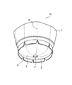
図1は、本発明による易廃棄性プラスチックカップの底部を示す斜視図である。
本発明による易廃棄性プラスチックカップ10は、真横、あるいは斜め上から見た外見は、通常の逆円錐台形状の側壁1と、周辺に糸尻3を有する底板2と、開口部のフランジ4(図2参照)とからなる射出成形されたプラスチックカップと略同様であるが、糸尻3には複数個の切り欠き8を備えている。
しかるに、下側から見える本発明による易廃棄性プラスチックカップ10の底板2は、図1に示すように外方向に湾曲している。
また、本発明による易廃棄性プラスチックカップ10の側壁1と底板2の内面には、中心軸9を通る単数もしくは複数の垂直断面と交わる部分に凹陥溝による連続した薄肉ライン5が、また薄肉ライン5に当接する糸尻3部分には、外側に向かって開く切り欠き8が、それぞれ設けられている。これら薄肉ライン5は、外側からは一切目視することができない。
この凹陥溝の横断面は、V字状であっても、U字状であっても、あるいは段階的に中央が深くなる形状であってもよい。
側壁1と底板2の内面における複数本の薄肉ライン5は、図1に示すように、側壁1において縦縞状に等間隔に設けられ、その総本数は、全円周で6〜10本程度が好ましい。本数が、余り多すぎると胴部が柔軟構造になり過ぎ、また少なすぎると、胴部を押し潰す場合の方向性が限定されるばかりか全体としての反復力が大きくなり過ぎる。
一般に射出成形のゲート7は、底部の中心に設けられているので、薄肉ライン5はゲート7を通過するように設けられ、別の表現によれば、薄肉ライン5は、ゲート7から所定の角度差をもって放射されるように設けられている。そして、その薄肉ライン5が当接する糸尻3部分に設けられている切り欠き8は、一般に厚みのある糸尻3を折り曲げる場合の折り曲げ抵抗を無くするためのものである。
【0006】
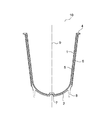
図2は、本発明による易廃棄性プラスチックカップの薄肉ラインを通過する断面図である。
図2に示すように、側壁1と底板2は連接しており、それらの内側には所定の深さの凹陥溝による薄肉ライン5が連続して形成されている。
この薄肉ライン5の最も薄くなっている部分の厚みは逆円錐台形のプラスチックカップを手で、余り抵抗なく略偏平状に、且つ大きく復元しない程度に折り畳むことができる厚さにあることが望ましく、本発明による易廃棄性プラスチックカップ10のプラスチック素材がポリプロピレン樹脂の場合で最低厚みが、0.05〜0.3mmの範囲にあることが好ましい。
側壁1の表面は、平らな逆円錐状のプラスチック曲面であってその上に直接印刷層を設けるか、粘着ラベル等を貼着するか、若しくは、図2に示すように予め射出成形金型内にインサートされた単層若しくは積層構成のラベル6を一体的に貼着させるようにしてもよい。
【0007】
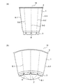
図3は、本発明による易廃棄性プラスチックカップの減容化の説明図である。
図3(a)は、本発明による易廃棄性プラスチックカップ10の側面図であり、図3(b)は押し潰された状態図である。
本発明による易廃棄性プラスチックカップ10は、使用後、胴部と底部を指で挟んで押さえると対向する2本の薄肉ライン5(図では5−1)によって折れ曲がり胴部、底部共に略偏平に押し潰される。
図3(b)は、薄肉ライン5−1によって完全に押し潰された状態図であるが、実際には、薄肉ライン5−1部分のみならず、その他の部分の復元力によって若干元の状態に戻り結果的に僅かに膨らんだ状態となる。しかし、この状態でも減容化には大きく貢献する。
この押し潰しにあたって、側壁1の外側に板紙による単層片あるいは紙、アルミ箔等を含む積層片が貼着されている場合には、そのような素材のプラスチックよりも強い塑性変形性によって、より偏平に近い状態に押し潰すことができる。
なお、底板2は皺を伴って潰れ、糸尻3の外側に現れる。
【0008】
本発明による易廃棄性プラスチックカップ10に使用されるプラスチック素材は、中密度ポリエチレン、高密度ポリエチレン、ポリプロピレン、ポリエチレンテレフタレート、ポリカーボネート、アクリルニトリルコポリマー、ハイインパクトポリスチレン等の射出成形グレードであって、GPポリスチレンのように折り曲げによって割れが生じるものは危険性を伴うので使用を避けた方がよい。
また、炭酸カルシウム、酸化マグネシウム等の無機質フィラーを耐内容物性に支障のない程度に混入したプラスチック素材は、塑性変形性が良好になるので、押し潰し易くなり好ましい。
一方で、ゴム系の素材をブレンドしたり、あるいはケミカルブレンドによって素材自体が柔軟で、復元力を有するものは使用上好ましくない。
また、射出成形金型のキャビティ内に印刷ラベル6を予めインサートしておいてから射出成形を行うインモールドラベリング方式を採用する場合には、ラベル5の素材として、紙、板紙、アルミ箔等、射出成形に使用するプラスチックよりも塑性変形性の強いものを使用することが好ましい。
【0009】
本発明による易廃棄性プラスチックカップ10の表面の印刷には、シルクスクリーン印刷、ドライオフセット印刷等の直接曲面印刷法、あるいは曲面転写印刷法等公知のいかなる印刷方式を用いてもよく、また、射出成形金型のキャビティ内に印刷ラベル6を予めインサートしておいてから成形するインモールドラベリング方式を用いてもよい。
【0010】
【発明の効果】
本発明によれば、剛性のあるプラスチックカップの底板2を外側に湾曲させ、側壁1と底板2の内面に、底板2の中心から所定の角度差で放射する複数本の凹陥溝からなる薄肉ライン5を設け、且つ、この薄肉ライン5が接近する糸尻3部分に外側に開く切り欠き8を設けることによって、使用後、対向するいずれかの2本の薄肉ライン5によって、略偏平に押し潰すことができ、減容化による廃棄性に優れたプラスチックカップを提供することができる。
【図面の簡単な説明】
【図1】本発明による易廃棄性プラスチックカップの底部を示す斜視図
【図2】本発明による易廃棄性プラスチックカップの断面図
【図3】本発明による易廃棄性プラスチックカップの減容化の説明図
【符号の説明】
1 側壁
2 底板
3 糸尻
4 フランジ
5 薄肉ライン
6 ラベル
7 ゲート
8 切り欠き
9 中心軸
10 本発明による易廃棄性プラスチックカップ[0001]
BACKGROUND OF THE INVENTION
The present invention relates to an easily disposable plastic cup that can be reduced in volume by use, such as folding and crushing.
[0002]
[Prior art]
In general, an injection molded plastic cup has an opening, a body, and a bottom that are integrally molded. Either use it as it is, or after filling the contents in the plastic cup, cover the flange of the opening. It is connected and used as a container, and after use it is almost discarded as it is.
[0003]
[Problems to be solved by the invention]
Plastic cups by injection molding retain rigidity before and after use, so they must be discarded as they are after use, and they are extremely disposable compared to paper cups that can be crushed or folded freely. There is a problem of being bad.
The present invention has been made in view of this problem, and an object thereof is to provide a plastic cup that achieves volume reduction by crushing.
[0004]
[Means for Solving the Problems]
An easy-to-dispose plastic cup according to the present invention is an injection-molded plastic cup comprising an inverted frustoconical side wall, a bottom plate having a thread tail around the periphery, and a flange of an opening, and the bottom plate is curved outward. A thin line formed by a recessed groove on the inside of the side wall and the bottom plate that intersects with one or a plurality of vertical sections passing through the central axis of the plastic cup, and a notch that opens outward at the yarn bottom that intersects the vertical section Are respectively provided. Moreover, it is good also as a structure which affixed the label integrally on the side wall outer surface at least among the said side wall outer surface and the said baseplate outer surface within an injection mold.
[0005]
DETAILED DESCRIPTION OF THE INVENTION
The present invention will be described in more detail with reference to the drawings.
FIG. 1 is a perspective view showing the bottom of an easily disposable plastic cup according to the present invention.
The easy-to-dispose
However, the
Further, on the inner surface of the
The cross section of the recessed groove may be V-shaped, U-shaped, or may have a shape where the center deepens stepwise.
As shown in FIG. 1, the plurality of
In general, since the injection-molded
[0006]
FIG. 2 is a cross-sectional view through a thin line of a readily disposable plastic cup according to the present invention.
As shown in FIG. 2, the
The thickness of the thinnest part of the thin-
The surface of the
[0007]
FIG. 3 is an explanatory view of volume reduction of an easily disposable plastic cup according to the present invention.
FIG. 3A is a side view of the easily disposable
The easy-to-dispose
FIG. 3B is a state diagram that is completely crushed by the thin line 5-1, but in actuality, not only the thin line 5-1 part, but also the original state slightly due to the restoring force of other parts. As a result, a slightly swollen state is obtained. However, this state also contributes greatly to volume reduction.
In this crushing, when a single-layer piece made of paperboard or a laminated piece containing paper, aluminum foil or the like is attached to the outside of the
The
[0008]
The plastic material used for the easily disposable
In addition, a plastic material in which an inorganic filler such as calcium carbonate or magnesium oxide is mixed to such an extent that the content resistance is not hindered is preferable because it is easy to be crushed because of good plastic deformation.
On the other hand, it is not preferable in use that a rubber-based material is blended or a material itself is soft and has a restoring force by chemical blending.
In addition, when adopting an in-mold labeling method in which the injection labeling is performed after inserting the
[0009]
For printing on the surface of the easily disposable
[0010]
【The invention's effect】
According to the present invention, the
[Brief description of the drawings]
FIG. 1 is a perspective view showing a bottom part of an easily disposable plastic cup according to the present invention. FIG. 2 is a cross-sectional view of an easily disposable plastic cup according to the present invention. Illustration [Explanation of symbols]
DESCRIPTION OF
Claims (2)
Priority Applications (1)
| Application Number | Priority Date | Filing Date | Title |
|---|---|---|---|
| JP36894799A JP4408317B2 (en) | 1999-12-27 | 1999-12-27 | Easily disposable plastic cup |
Applications Claiming Priority (1)
| Application Number | Priority Date | Filing Date | Title |
|---|---|---|---|
| JP36894799A JP4408317B2 (en) | 1999-12-27 | 1999-12-27 | Easily disposable plastic cup |
Publications (2)
| Publication Number | Publication Date |
|---|---|
| JP2001180640A JP2001180640A (en) | 2001-07-03 |
| JP4408317B2 true JP4408317B2 (en) | 2010-02-03 |
Family
ID=18493171
Family Applications (1)
| Application Number | Title | Priority Date | Filing Date |
|---|---|---|---|
| JP36894799A Expired - Fee Related JP4408317B2 (en) | 1999-12-27 | 1999-12-27 | Easily disposable plastic cup |
Country Status (1)
| Country | Link |
|---|---|
| JP (1) | JP4408317B2 (en) |
Families Citing this family (4)
| Publication number | Priority date | Publication date | Assignee | Title |
|---|---|---|---|---|
| JP4863039B2 (en) * | 2004-04-30 | 2012-01-25 | 株式会社吉野工業所 | Pressure-compatible container |
| JP3178468U (en) * | 2012-03-28 | 2012-09-20 | 孝 新庄 | Container for paste-like materials such as miso |
| FR3063882B1 (en) * | 2017-03-17 | 2021-12-24 | Newcy | REUSABLE AND STACKABLE CUP |
| JP7223943B1 (en) | 2022-01-21 | 2023-02-17 | 吉村化成株式会社 | container |
-
1999
- 1999-12-27 JP JP36894799A patent/JP4408317B2/en not_active Expired - Fee Related
Also Published As
| Publication number | Publication date |
|---|---|
| JP2001180640A (en) | 2001-07-03 |
Similar Documents
| Publication | Publication Date | Title |
|---|---|---|
| JP7838974B2 (en) | contents container | |
| JP4408317B2 (en) | Easily disposable plastic cup | |
| WO2005054066A1 (en) | In-mold container and apparatus for producing the same | |
| JP4422265B2 (en) | Easily disposable in-mold plastic cup | |
| JP3817600B2 (en) | Synthetic resin housing | |
| JP3027032B2 (en) | Manufacturing method of squeezed container with label | |
| JP2004067140A (en) | Food container | |
| JP4217030B2 (en) | In-mold container and manufacturing apparatus thereof | |
| JP4029600B2 (en) | Highly sealed container | |
| JP2021017265A (en) | Cup container, cup container with label, and cup packaging body | |
| JP7843698B2 (en) | contents container | |
| JP4441061B2 (en) | container | |
| JPH08207924A (en) | Composite container, its manufacturing method and its manufacturing apparatus | |
| JP2017149452A (en) | Hinge cap | |
| JP2594379Y2 (en) | Storage container | |
| JP3845924B2 (en) | Plastic Steion Tag Type Easy Open Mouth Plug | |
| JP2001180643A (en) | Easy disposable plastic cup | |
| JP3593724B2 (en) | Composite container | |
| JP4595203B2 (en) | Manufacturing method of barrier plastic cup container | |
| JPH10147357A (en) | Insert injection molded lid | |
| JP4202695B2 (en) | In-mold label container and manufacturing method thereof | |
| JP6651416B2 (en) | Double container | |
| JP7810678B2 (en) | container | |
| JP3954952B2 (en) | Dispensing container | |
| JP7522544B2 (en) | Container cap and nozzle replacement set for container cap |
Legal Events
| Date | Code | Title | Description |
|---|---|---|---|
| A621 | Written request for application examination |
Free format text: JAPANESE INTERMEDIATE CODE: A621 Effective date: 20061027 |
|
| A977 | Report on retrieval |
Free format text: JAPANESE INTERMEDIATE CODE: A971007 Effective date: 20090724 |
|
| A131 | Notification of reasons for refusal |
Free format text: JAPANESE INTERMEDIATE CODE: A131 Effective date: 20090807 |
|
| A521 | Written amendment |
Free format text: JAPANESE INTERMEDIATE CODE: A523 Effective date: 20091006 |
|
| TRDD | Decision of grant or rejection written | ||
| A01 | Written decision to grant a patent or to grant a registration (utility model) |
Free format text: JAPANESE INTERMEDIATE CODE: A01 Effective date: 20091104 |
|
| A01 | Written decision to grant a patent or to grant a registration (utility model) |
Free format text: JAPANESE INTERMEDIATE CODE: A01 |
|
| A61 | First payment of annual fees (during grant procedure) |
Free format text: JAPANESE INTERMEDIATE CODE: A61 Effective date: 20091109 |
|
| R150 | Certificate of patent or registration of utility model |
Free format text: JAPANESE INTERMEDIATE CODE: R150 |
|
| FPAY | Renewal fee payment (event date is renewal date of database) |
Free format text: PAYMENT UNTIL: 20121120 Year of fee payment: 3 |
|
| FPAY | Renewal fee payment (event date is renewal date of database) |
Free format text: PAYMENT UNTIL: 20131120 Year of fee payment: 4 |
|
| LAPS | Cancellation because of no payment of annual fees |