JP4406475B2 - Portable data transmission / reception terminal device and portable communication system using the same - Google Patents
Portable data transmission / reception terminal device and portable communication system using the same Download PDFInfo
- Publication number
- JP4406475B2 JP4406475B2 JP37576498A JP37576498A JP4406475B2 JP 4406475 B2 JP4406475 B2 JP 4406475B2 JP 37576498 A JP37576498 A JP 37576498A JP 37576498 A JP37576498 A JP 37576498A JP 4406475 B2 JP4406475 B2 JP 4406475B2
- Authority
- JP
- Japan
- Prior art keywords
- data
- terminal device
- transmission
- reception
- transmitted
- Prior art date
- Legal status (The legal status is an assumption and is not a legal conclusion. Google has not performed a legal analysis and makes no representation as to the accuracy of the status listed.)
- Expired - Lifetime
Links
Images


Landscapes
- Information Transfer Between Computers (AREA)
- Computer And Data Communications (AREA)
- Data Exchanges In Wide-Area Networks (AREA)
- Mobile Radio Communication Systems (AREA)
- Telephonic Communication Services (AREA)
Description
【0001】
【産業上の利用分野】
この発明は携帯型データ送受信端末装置およびそれを用いた携帯型通信システムに関し、特に電子メールやキャラクタ(記号等)等のデータを微弱電波で送受信する機能を有する携帯型データ送受信端末装置およびそれを用いた携帯型通信システムに関する。
【0002】
【従来技術】
従来、ポケットベルのような電子メールの送受信機能を持った携帯情報端末装置が知られている。従来の電子メール送受信システムでは、携帯端末(ペケットベル)が受信専用であり、送信側は電話機から公衆回線を通じてメールサーバーに接続してメッセージを蓄積させ、電子交換機,公衆回線及び携帯端末の存在するエリア近くのアンテナを通じて携帯端末へ送信される。この場合、携帯端末所有者に固有のID(メールアドレス)が割り当てられ、それを宛先情報として送信先を指定している。
【0003】
【発明が解決しようとする課題】
上述のような電子メール通信システムでは、電話回線を使用しなければならないので、通信設備が大型化し、携帯端末単体のコストに加えて通信設備の一部の費用も加入時に負担しなければならず、使用に際しては別途に回線使用料が必要となるため、携帯端末の所有及び使用に際して相応の負担が必要となる。特に、使用頻度の高いユーザーは、高額の使用料(通信費)を支払わなければならなくなる。また、電子メールサービス業者との契約が必要であり、そのサービス料も必要である。さらに、電子メールの着信は、メールサーバーに接続しなければ確認ができないので、着信メールを受信できる場所や使用できる場所の制約を受ける。また、メールを送信する場合は、必ず送信先を特定する(送信アドレス又は送信先番号)必要があり、不特定人向けにメッセージを伝達するような、メール通信をゲーム感覚で送信することができず、しかも多数の特定人にメールを送信するためには送信先数に比例した高額の通信費用が必要であった。
【0004】
それゆえに、この発明の主たる目的は、電話回線を使用せず、手軽に無料で電子メール等のデータを送受信することの可能な携帯型データ送受信端末装置およびそれを用いた携帯型通信システムを提供することである。
この発明の他の目的は、不特定人向けに電子メール等のデータを送信したい場合に、送信先の宛先情報を知らなくても、データを送信することが可能な携帯型データ送受信端末装置およびそれを用いた携帯型通信システムを提供することである。この発明のさらに他の目的は、不特定の端末装置を経由して、希望の相手に電子メール等のデータを送信することの可能な携帯型データ送受信端端末装置およびそれを用いた通信システムを提供することである。
【0005】
【課題を解決するための手段】
この発明は、電子メール等のデータを送受信するための携帯型データ送受信端末装置である。第1の発明の携帯型データ送受信端末装置は、記憶手段と表示手段を備え、さらに、他の端末装置と無線通信する通信手段と、送信制御手段と、記憶制御手段と、表示制御手段とを備える。送信制御手段は、通信手段の通信可能エリア内にある他の端末装置に対して、記憶手段に記憶されたデータを自動的に送信する。記憶制御手段は、通信可能エリア内の他の端末装置から送信されたデータを自動的に受信して記憶手段に記憶させる。表示制御手段は、記憶手段に記憶されている受信データを表示手段に表示させる。
【0006】
第2の発明の携帯型データ送受信端末装置は、携帯型データ端末装置と、携帯型データ端末装置に対して着脱自在なカートリッジとを備える。携帯型データ端末装置は、少なくとも受信データを表示する表示手段と第1の処理手段とを備える。カートリッジは、他の端末装置と無線通信する通信手段と、少なくとも受信データを記憶するための記憶手段と、第2の処理手段とを備える。第1の処理手段は、記憶手段に記憶されている受信データを表示手段に表示させる。第2の処理手段は、 通信手段と通信可能エリア内に存在する他の端末装置に対して、記憶手段に記憶されたデータを自動的に送信し、通信可能エリア内に存在する所定の関係にある他の端末装置から送信されたデータを自動的に受信して記憶手段に記憶させる。
【0007】
【作用】
第1の発明の携帯型データ送受信端末装置では、或る携帯型データ送受信端末装置(送信側)の通信手段が送信すべき送信データを無線通信によって送信する。その無線通信を受信可能なエリア内に存在する他の携帯型データ送受信端末装置(受信側)の通信手段がその送信データを受信し、受信側の記憶制御手段がその受信データを受信側の記憶手段に記憶する。また、表示制御手段は、記憶手段に記憶されている受信データを受信側の表示手段に表示させる。好ましくは、送信データを受信可能な携帯型データ送受信端末装置を特定するために、送信データの送信に際して宛先情報が付加される。
【0008】
第2の発明の携帯型データ送受信端末装置では、或る携帯型データ送受信端末装置(送信側)に対応するカートリッジに含まれる通信手段が送信データを他の携帯型データ送受信端末装置(受信側)へ自動的に無線通信によって送信する。そのとき、通信可能なエリア内に存在する他の携帯型データ送受信端末装置(受信側)に対応するカートリッジに含まれる通信手段がその送信データを自動的に受信し、第1の処理手段がその受信データを記憶手段に書込むことにより、記憶させる。そして、カートリッジが他の携帯型データ送受信端末装置(受信側)に装着されると、第2の処理手段が記憶手段に記憶されている受信データを表示手段に表示させる。
【0009】
これによって、携帯型データ送受信端末装置の所有者は、不特定人又は特定人からの送信データを自動的に受信し、その受信データを見たり読んだりすることができ、特定人からのメール(又はメッセージ)や不特定人からのメールや宣伝広告情報(お買い得情報)等の様々な情報を通信費用をかけることなく入手でき又は収集でき、携帯型データ送受信端末装置又はカートリッジを持って出掛けることによって様々な楽しみを得たり、情報交換することができる。
【0010】
【発明の効果】
この発明によれば、電話回線を使用せず、どこからでも手軽に、しかも無料で電子メール等のデータを送受信することができる。また、不特定人向けに電子メール等のデータを送信したい場合は、送信先の宛先情報を知らなくても、データを送信することができる。さらに、特定の相手に電子メール等のデータを送信したい場合は、不特定の端末装置を経由してデータを送信することもできる。
【0011】
【発明の実施の形態】
図1はこの発明の一実施例の携帯型データ送受信端末装置を用いて文字データ等の送信データを無線通信によって通信し又は伝達していく原理を図解的に示した図である。例えば、携帯型データ送受信端末装置(図示及び以下の説明では、「端末」又は「送受信端末」と略称する)Aが送信データを無線電波によって送信すると、その無線電波を受信可能なエリア内に存在する他の端末B,C,Dが送信データを受信する。このとき、端末Aが送信する無線電波は、電波取扱法に基づく免許を必要としない微弱電波であることが好ましい。他の端末B,C,Dは、その受信データが自己の宛先のものでなければ、後述の間接メールに該当する場合であれば、受信データを転送する。また、不特定多数に転送することを目的とするメール、例えば後述の広告等の情報であれは、直接メールでも間接メールでもない場合であっても、エリア内に存在する他の端末E,F,Gに転送される。
【0012】
以下、図面を参照してこの発明の実施例を説明するが、説明を簡単にするために、送受信データは電子メール又は不特定人向けのメールを想定して説明する。不特定人向けのメールは、例えばニュースや広告やお買い得情報等のたわいのないメッセージ又は不特定多数の人が読んでも差支えのないメッセージ等である。具体的には、送受信データとしては、次の3種類が考えられる。
(1) 直接メールを出す場合
端末Aが宛先を指定して特定の端末(例えばD)に直接送信する場合である。電子メールの宛先情報と送受信端末のユーザー識別情報が所定の関係にある(例えば一致した)端末Dにのみ、送信データが継続的に記憶され、当該ユーザーのみがそのメールを見ることができる。但し、通信可能エリア内に宛先となる特定の端末(例えばG)が存在しない場合は、電子メールが届かない場合もあるが、送信側(A)と受信側(G)の両者が通信可能なエリア内に近づいたときに電子メールが転送されることになる。
(2) 間接メールを出す場合
端末Aが宛先を指定して特定の端末(G)に送信する場合であり、送信者と受信者の間に存在する1以上の他の端末がユーザーの意思とは無関係に中継通信(またはメールの転送)を行う。後述の実施例では、中継を行う端末(D)が、宛先となる端末(G)のユーザー識別情報をアドレス帳に設定記憶している場合、端末Dが受信したデータを一時記憶しておき、移動して端末Gに近づき通信可能なエリア内に来たとき、端末Gに対して端末Aからのメールを転送する。なお、複数の不特定の端末B,C及びE,Fが次々と中継を行うことにより、特定の端末Gに転送してもよい。この場合、中継する端末B,C,Dはメッセージの内容を見ることができないように、自己を宛先情報とするメールだけを読めるようにプログラム的に設定される。中継となる端末B〜Fの存在によって、通信可能エリア内に宛先端末装置が存在しない場合でも、次々と転送されることにより電子メールがより遠くの特定の端末Gに届けられる。
(3) ニュースや広告等のようにユーザーが積極的に受信選択していないメールを転送する場合
宛先を指定せず不特定多数の端末装置に送信する場合は、通信可能エリア内の全ての端末に向けて送信され、全ての端末が受信できるとともに、その受信データの内容を読むことができる。
なお、送受信データは、文字データ(又は文字コード)に限らず、図形又は記号や、写真撮影した画像データでもよい。以下の説明では、送受信するデータを総称してメール等と呼ぶ。
【0013】
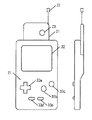
図2はこの発明の一実施例の携帯型データ送受信端末装置および/またはデータ表示・作成装置の外観図である。携帯型データ送受信端末装置(以下、「端末」又は「送受信端末」と略称する)10は、送受信機能を備えたカートリッジ20とデータ表示・作成装置30とを組み合わせて構成される。カートリッジ20は、データ表示・作成装置30に対して着脱自在かつ装着されたときに電気的に接続可能に構成される。
カートリッジ20は、データの送受信機能及び受信データの記憶機能を有し、単独で持ち歩くことにより他のカートリッジ(単独で使用する場合は、このカートリッジが端末としての機能を果たすこともある)とのメール等の送受信(又はメール通信)を行うものである。カートリッジ20は、ハウジング21にアンテナ22を形成し、ハウジングの21の外部から見える位置に受信状態を知らせるための発光ダイオード(LED)等の表示部23が形成され、その下方にデータ表示・作成装置30と接続するためのコネクタ24が形成される。
一方、データ表示・作成装置30は、送信すべきメール等を作成したり、受信したメール等を表示するものであって、ハウジング31の一方主面(表面)に液晶等の表示器32を設けるとともに、その下方に複数の操作スイッチ33a〜33eを設け、ハウジング31の他方主面(裏面)にカートリッジ20を挿入するための挿入部34を形成している。
【0014】
上述のカートリッジ20をデータ表示・作成装置30に装着して、組み合わせて使用する状態(すなわち、受信データを読む場合の携帯型データ送受信端末装置10として使用する状態)が図3に示される。なお、端末10の所有者(ユーザー)が外出する場合は、外出中に受信した受信データを読むためにはカートリッジ20とデータ表示・作成装置30の両方を洋服のポケットやかばん等に入れて所持し、外出中はデータの送受信のみ行いかつ帰宅後に受信データを読みたいときはカートリッジ20だけを所持して外出することになる。
【0015】
なお、図2及び図3の実施例では、端末10がカートリッジ20とデータ表示・作成装置30に分離可能な場合を説明したが、図4に示すように一体型の端末100で構成してもよい。その場合は、カートリッジ10に含まれる部品(後述の図5参照)が端末100のハウジング131内に収納され、端末100からはアンテナ122が露出されることになる。なお、その他の部分については、図2実施例の対応する部分に2桁の対応する数字の頭に百番の数字を追加して示し、詳細な説明を省略する。
【0016】
図5はカートリッジ20のブロック図である。図5において、カートリッジ20は、アンテナ22とLED23を基板25に実装するとともに、各種の電子部品を実装することにより回路部260を構成する。回路部260は、通信ユニット261と、CPU262と、ワークRAM264と、リセットIC265と、ROM266と、SRAM267と、電源切替回路268と、SRAM用電池269と、マルチバンクコントローラ(MBC)271と、コネクタ273と、電池274を含んで構成される。通信ユニットは、電波取締法による免許の不要な微弱電波を送受信する送信機と受信機を含み、文字データやキャラクタ,記号等のデータ等のコード又はドットデータを変調して送受信するものである。CPU262は、内蔵するROM263のプログラムデータに基づいて、通信ユニット261の送受信動作,ワークRAM264及びS−RAM267の書込・読出制御を行うとともに、データ表示・作成装置30のCPU35との間でデータの授受を行う。このCPU262及びROM226は、メモリバンクコントローラ(以下「MBC」と略称する)271及びコネクタ237を介してデータ表示・作成装置30のコネクタ36と電気的に接続される。また、CPU262にはリセットIC265が接続される。MBC271は、CPU35からアクセス可能なアドレスバスの特定アドレスデータに基づいて、CPU35からから見てROM266,S−RAM276,CPU262の何れをCPU35のアドレスバスに接続するかを切り換えるものである。MBC271は、必要に応じて日時及び時刻を計時するタイマが内蔵され、通信時の時刻データを送信データに付加して送信する必要がある場合の時刻データ発生源として利用される。
【0017】
ROM263には、カートリッジ20が送受信端末として単独で使用されるときの通信プログラム(後述の図10〜図13に示すフローチャートの機能を実現するためのプログラム)が予め記憶され、CPU262によって実行される。ROM266には、カートリッジ20がデータ表示・作成装置30に装着されたとき、CPU35によって実行される受信データの表示及び/又は送信データの作成のためのプログラム(後述の図14及び図15に示すフローチャートの機能を実現するためのプログラム)が予め記憶されている。
【0018】
図6はデータ表示・作成装置30のブロック図である。図6において、データ表示・作成装置30は、CPU35を含む、CPUがコネクタ36を介してカートリッジ20のコネクタ273に接続される。また、CPU35には、液晶表示器32及び操作スイッチ33が接続される。
【0019】
図7はS−RAM267の記憶領域を図解的に示した図である。図において、S−RAM267には、受信データ記憶領域267a,送信データ記憶領域267b,アドレス帳記憶領域267c及びユーザー識別情報(ID情報)記憶領域267dを含む。受信データ記憶領域267aは、他の端末から受信したメール等のデータを記憶する領域である。送信データ記憶領域267bは、データ表示・作成装置30に装着して使用されることにより、ユーザーが操作スイッチ33の操作によって入力された送信データを記憶する領域である。受信データ記憶領域267a及び送信データ記憶領域267bには、送信すべきメールデータ(送信データ本体)だけでなく、メールデータに付加される各種データ(例えば、図9に示すれていは信号種別,自己ID.端末ID,送信データ,チェックサム,タイミング情報,受信済フラグ等)も記憶される。受信済フラグは、直接メール転送方法により同じメールを受信済であることを示すフラグである。
ユーザーID情報は、送受信端末装置を特定するための情報であり、例えば氏名,住所,生年月日,電話番号等であるが、他の端末と識別可能な文字又は数字列としてもよい。アドレス帳データ記憶領域267cには、使用者が通信を希望する複数の相手となる他の端末のユーザーID情報である。これは、間接メール転送方法によりメールを転送する場合に、中継するか否かの判断ためのID情報として使用される。例えば、アドレス帳データ記憶領域267cには、友人の端末固有のユーザーID情報が1以上予め設定登録されており、友人宛ての宛先情報の付されたメールを受信したときは、当該カートリッジ10がそのメールの転送を中継する中継器として働くことになる。
【0020】
再び、図5を参照して、電源切換回路268は、カートリッジ10がデータ表示・作成装置30に装着され、かつデータ表示・作成装置30から電源が供給されているときは電池269の電力供給を休止し、データ表示・作成装置30から電源が供給されていないときは電池269の電力をS−RAM267に供給してS−RAM267の記憶データが揮発するのを防止している。
図6は、データ表示・作成装置30のブロック図である。図6において、データ表示・作成装置30は、表示装置31と、入力装置32と、CPU35と、送受信端末装置20と接続するためのコネクタ36を含んで構成される。
【0021】
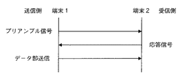
図8は、データの送受信の手順の概略を示した図である。図9は、通信データのフォーマットを示した図である。
次に、図8および図9を参照して、データの送受信の手順を説明する。まず、送信側の送受信端末装置1は、データの送信に先立ってプリアンブル信号を送信する。プリアンブル信号は、図9に示すように、信号種別と、自己IDと、送信データ情報と、チェックサム部とで構成される。信号種別はプリアンブル信号,応答信号,データ本体信号を区別するためのデータである。自己IDは送信側の送受信端末装置1のユーザーID情報である。送信データ情報は、送信する電子メール等の作成日時,作成者のユーザーID情報,宛先のユーザーID情報,電子メールかニュースかを識別するためのデータ種別,電子メールの場合に直接メールか間接メールかを識別するためのモード種別および有効期限データ等を含む。有効期限データは、例えば送受信データがスーパーマーケットの安売り情報やイベント情報というニュースデータである場合に、安売り期間やイベント期間を過ぎたらそのデータをSRAM267から削除するための情報である。 チェックサム部は正しいデータを受信したかどうかをチェックするために使用される。
【0022】
受信側の送受信端末装置2は、プリアンブル信号を受信して、プリアンブル信号に含まれる送信データ情報に基づいて自分が受け取るべき電子メール等であるか否かを判断し、受け取るべき電子メールである場合には応答信号を送信する。応答信号は、プリアンブル信号と同様に、信号種別,自己ID,送信データ情報およびチェックサム部を含む。これらに加えて、送信側の送受信端末装置1のユーザーID情報(プリアンブル信号に含まれていたユーザーID情報)とタイミング情報を含む。タイミング情報は送信側の送受信端末装置1の送信タイミングと受信側の送受信端末装置2の受信のタイミングをあわせるためのものであり、具体的には応答信号送信後何秒後という情報である。
【0023】
送信側の送受信端末装置1は、プリアンブル信号を送信後、受信側の送受信端末装置2から応答信号が送信されるのを待つが、応答信号を受信すると応答信号に含まれるタイミング情報にあわせて、データ本体信号を送信し、受信側の送受信端末装置2がこれを受信する。
【0024】
図10は、通信プログラムのメインルーチンのフローチャートである。図11および図12はメインルーチンフローチャートにおける送信サブルーチンおよび受信サブルーチンのフローチャートである。図13は、受信サブルーチンにおいて受信すべきか否かの判断処理(ステップ124)の詳細を示したフローチャートである。
【0025】
次に、図10ないし図13を参照して、この実施例の通信時の動作について説明する。 送受信端末装置20に電池274を装着するとCPU262はROM263に記憶された通信プログラムを実行する。まず、ステップ10において、ユーザーID情報が入力されているか否かが判定され、入力されていない場合は、ステップ10を繰り返してユーザーID情報の入力を待つ。つまり、ユーザーID情報が入力されない限り送受信端末装置20は通信を行わない。ここで、使用者は、送受信端末装置20をデータ表示・作成装置30に装着し、ユーザーID情報を表示装置31と入力キー32を使用して入力する。ユーザーID情報が入力されると、ステップ11に進み、以後ステップ11〜ステップ15を繰り返す。具体的には、 ステップ11において、後述の図11に示す送信サブルーチンが実行される。続いてステップ12において、後述の図12に示す受信サブルーチンが実行される。ステップ14において、SRAM267内に記憶されている電子メール等のうち、有効期限の切れたものが削除される。ステップ15において、時間待ち処理が行われる。これは、送受信の間隔を取って、消費電流を抑えて電池274の持続時間を長くするためのものである。
【0026】
送受信端末装置20は、電池274の寿命が尽きるまでステップ11〜ステップ15を繰り返す。ただし、表示・作成装置装着時は、CPU262は非動作状態となり、CPU35によって後述する図14に示すデータ表示・作成プログラムが実行される。再び表示・作成装置がはずされると、CPU262が動作して、ステップ10の後、ステップ11〜ステップ15の動作を繰り返す。
【0027】
図11を参照して、送信サブルーチンの詳細を説明する。送信サブルーチンでは、他の送受信端末装置から受信してSRAM267内の受信データ領域201に記憶されたデータや、後述する図15に示す表示・作成プログラムの新規作成サブルーチンで作成されSRAM267内の自己送信データ領域202に記憶されたデータが送信される。まず、ステップ111において、送信すべきデータがあるか否か、すなわち、SRAM267内の受信データ領域201(自分宛ての電子メールを除く)および自己送信データ領域202(受信済みの直接メールを除く)に電子メール等があるか否かが判断される。送信すべきデータがない場合は、送信サブルーチンを終了してメインルーチンに戻る。送信すべきデータがある場合は、ステップ112に進み、プリアンブル信号を送出する。ステップ113において応答信号の受信を待ち、受信後ステップ114に進む。ステップ114において、受信した信号に含まれる信号種別に基づいて受信した信号が応答信号であるか否かが判断されるとともに、サムチェックをおこなって受信信号が正しいか否かが判断される。受信信号が応答信号でないか正しい信号でない場合はステップ119に進む。応答信号であり正しい信号である場合は、ステップ115に進み、応答信号に含まれる送受信端末装置1IDおよび送信データ情報に基づいて、自己のプリアンブル信号に対する応答か否かを判断する。自己のプリアンブル信号に対する応答でない場合には、ステップ119に進む。自己のプリアンブル信号に対する応答である場合には、ステップ116において、応答信号に含まれるタイミング情報に基づく送信タイミングでデータが送信される。ステップ117において、送信したデータが直接メールか否かが判断される。直接メールである場合は、ステップ118において、SRAM267内の自己送信データ領域202の受信済みフラグが立てられる。直接メールでない場合は、ステップ119に進む。ステップ119において、他に送信すべきデータがあるか否かが判断され、他にある場合は、ステップ112に戻る。ない場合は、送信サブルーチンを終了してメインに戻る。
【0028】
図12ないし図13を参照して、受信サブルーチンの詳細を説明する。受信サブルーチンでは、ステップ121において、SRAM267内の受信データ領域201に書き込みエリアが残っているか否かが判断される。残っていない場合は、受信サブルーチンを終了してメインルーチンに戻る。残っている場合は、ステップ122において、受信をおこなう。受信がない場合は、受信サブルーチンを終了してメインルーチンに戻る。受信があった場合は、ステップ123において、受信した信号がプリアンブル信号であるか否かが判断されるとともに、サムチェックをおこなって受信した信号が正しいか否かが判断される。受信した信号がプリアンブル信号でないか正しい信号でない場合は、受信サブルーチンを終了してメインルーチンに戻る。プリアンブル信号であり正しい信号である場合は、ステップ124において、後述する図13において詳細に示されるようなデータを受信すべきか否かの判断がされる。受信すべきデータでない場合は、受信サブルーチンを終了してメインルーチンに戻る。受信すべきデータである場合は、ステップ125において、応答信号を送信し、続くステップ126において、応答信号に含まれるタイミング情報に基づいたタイミングで受信する。ステップ127において、受信した信号がデータ本体信号であるか否かが判断されるとともに、サムチェックをおこなって受信した信号が正しいか否かが判断される。受信した信号がデータ本体信号でないか正しい信号でない場合は、受信サブルーチンを終了してメインルーチンに戻る。データ本体信号であり正しい信号である場合は、ステップ128に進み、データをSRAM267内の受信データ領域201に保存して、受信サブルーチンを終了してメインルーチンに戻る。
【0029】
図13を参照して、受信サブルーチンのステップ124における受信すべきか否かの判断を詳細に説明する。まず、ステップ1241において、プリアンブル信号に含まれる送信データ情報に基づいて送信されるデータがニュースか否かが判断される。ニュースである場合はステップ1247に進む。ニュースでない場合はステップ1242に進み、直接メールか否かが判断される。直接メールである場合は、ステップ1243において宛先が自分か否かが判断され、自分である場合は、ステップ1247に進む。自分でない場合は受信すべきデータでないと判断される。ステップ1242において、直接メールでないと判断された場合は、ステップ1244において、間接メールか否かが判断され、間接メールでない場合は受信すべきデータでないと判断される。間接メールである場合は、ステップ1245において宛先が自分か否かが判断され、自分である場合はステップ1247に進む。自分でない場合はステップ1246に進み、宛先がアドレス帳データに載っているか否かが判断される。アドレス帳データに載っている場合は、ステップ1247に進む。アドレス帳データに載っていない場合は、受信すべきデータでないと判断する。
ステップ1247においては、SRAM267内の受信データ領域201または自己送信データ領域202に同じデータがないか否かが判断される。具体的には、プリアンブル信号に含まれる送信データ情報とSRAM267内に記憶されているデータの送信データ情報を比較することによって判断される。ステップ1247において、同じデータを持っていないと判断された場合は、受信すべきデータであると判断される。同じデータを持っていると判断された場合は、受信すべきデータでないと判断される。
【0030】
図14は表示・作成プログラムのメインルーチンのフローチャートである。図15はメインルーチンのフローチャートにおける新規送信サブルーチンのフローチャートである。図16ないし図18は、このプログラムの実行画面の一例である。
次に図14ないし図18を参照して、この実施例のデータ表示・作成時の動作について説明する。
【0031】
送受信端末装置20にデータ表示・作成装置30を装着すると、CPU262が非動作状態となり、CPU35がROM266に記憶された後述する図14および図15に示す表示・作成プログラムを実行する。図16は、データ表示・作成装置装着時に最初に表示される画面の一例である。ここでは、受信データの一覧が表示される。図16において、選択カーソル44は入力キー32aの上下方向の入力によって移動する。データが一画面内に入りきらない場合、カーソル44が上下端まで行くと一覧表示40はスクロールする。内容表示ボタン41,新規送信ボタン42,自己送信メール表示ボタン43は、いずれかが選択されており(白黒反転表示)、入力キー32aの左右方向の入力によって選択を変更できる。これらのボタンを選択して入力キー32bを押すことによって、それぞれ図17に示すような内容表示画面,図18に示すような新規送信画面、自己送信メール表示画面が表示される。なお、自己送信メール表示画面は図16と略同様である。
【0032】
表示・作成プログラムでは、まず、ステップ131において、ユーザーID情報が入力済みか否かが判断される。入力済みでない場合は、ステップ132においてユーザーID情報の入力が要求される。入力済みの場合は、ステップ133に進む。ステップ133において、図16に示すような受信データ一覧表示画面が表示される。この画面で、ステップ134において内容表示ボタン41が押されたことが判断されると、ステップ135において、図17に示すような内容表示画面が表示される。ステップ136において新規送信ボタン42が押されたことが判断されると、ステップ137において、後述する図15に示す新規送信サブルーチンが実行される。ステップ138において自己送信メール表示ボタン43が押されたことが判断されると、ステップ139において、図16と略同様の自己送信メール表示画面が表示される。
【0033】
図17を参照して、内容表示画面を説明する。内容表示画面では、一覧表示画面の選択カーソル44で指定されたデータの内容を表示する。内容表示領域50にデータの内容が表示される。データが一画面内に入りきらない場合、内容表示領域50は入力キー32aの上下方向の入力によってスクロールする。「このメールに返信」ボタン,「このメールを転送」ボタン,「受信メール一覧に戻る」ボタンは、いずれかが選択されており、入力キー32aの左右方向の入力によって選択を変更できる。これらのボタンを選択して、入力キー32bを押すことによって、それぞれの処理が行われる。
【0034】
図15および図18を参照して、新規送信サブルーチンを説明する。新規送信サブルーチンでは、新規に送信する電子メール等を作成する。図18は表示画面の一例である。図18において、新規送信画面は上下2分割されており、上半分は作成中の電子メール等が表示される作成領域60である。下半分は、所謂ソフトウェアキーボード61が表示される。ソフトウェアキーボード61中のそれぞれのキーは、入力キー32aによって選択される。選択中のキーは白黒反転で表示される。入力キー32bを押すことによって選択中のキーに対応した文字が作成領域60のカーソル位置に表示される。この動作を繰り返すことによって電子メール等が作成される。電子メール等の作成が終了すると、送信ボタン62を入力キー32aによって選択して入力キー32bを押す。すると、宛先,データ種別,モード種別,有効期限の入力が要求され、これらの入力データに、作成日時,作成者ユーザーID情報が付加されて送信データ情報が作成される。データ本体と送信データ情報がSRAM267内の自己送信データ領域202に記憶される。記憶されたデータは、データ表示・作成装置30がはずされた後に、通信プログラムの送信サブルーチンにおいて自動的に送信される。
【0035】
新規作成サブルーチンでは、まず、ステップ140において、SRAM267内の自己送信データ領域202に書き込みエリアが残っているか否かが判断され、残っていない場合は、新規送信サブルーチンを終了してメインルーチンに戻る。残っている場合は、ステップ141において、上述したようにソフトウェアキーボードによって新規送信データが作成される。作成が終了すると、ステップ142において、送信データ情報(宛先,データ種別,モード種別,有効期限)の入力が要求される。続くステップ143において、送信データ情報に作成日と作成者ID情報が付加される。ステップ144において、データ本体と送信データ情報がSRAM267内の自己送信データ領域202に記憶されて、新規作成サブルーチンを終了してメインルーチンに戻る。
【0036】
送受信データは、電子メールまたはニュースだけではなく、画像データ、音声データ、ゲームデータ等も同様にして送受信することができる。この場合は、送信データ情報のデータ種別によって電子メールとニュースを区別するだけでなく、上記したような他のデータを区別できるようにすればよい。
ゲームデータは、例えば、ゲームプログラムROM(半導体ROMおよびCD−ROM等を含む)に予め記憶されていないキャラクターデータやアイテムデータ等とすることができる。
また、送受信端末装置20の受信機能を削除し送信機能のみ持った端末装置を、例えば宅急便のトラックに取り付けておくことによって、より広範囲にデータを拡散させることができる。
【0037】
図19は、この発明の他の実施例の固定型データ作成・送信装置のイメージ図である。先に述べた実施例では、データ表示・作成装置30を接続して作成したデータを送受信端末装置20間で送受信するものであった。それに対して、本実施例の固定型データ作成・送信装置は、より複雑なデータを作成することができ、作成したデータを送信する。送信されたデータは送受信端末装置Aが受信し、送受信端末装置Aがさらに送受信端末装置Bに送信する。
【0038】
図20は、固定型データ作成・送信装置の外観図およびブロック図である。図20において、固定型データ作成・送信装置70は、表示装置71と、パーソナルコンピュータ72と、通信ユニット76と、入力装置を備える。 入力装置は、キーボード73と、スキャナ74と、マイク75がある。さらにデジタルカメラ等を使用してもよい。様々な入力装置を用意することにより、複雑なデータを作成することができる。 パーソナルコンピュータ72はハードディスク721を含む。ハードディスクにはデータ作成プログラムおよびデータ送信プログラムが予め記憶されており、さらに、作成したデータが記憶される。データ作成プログラムおよびデータ送信プログラムは先に述べた実施例と略同様であるので省略する。
キーボード73,スキャナ74,マイク75等を使用してデータが作成され、ハードディスク721に記憶される。そして、ハードディスク721のデータが読み出されて、通信ユニット76を通じて送信される。
【0039】
本実施例の固定型データ作成・送信装置は、例えば、スーパーマーケット等の店舗に設置して、安売り情報や商品の詳細情報を発信したり、イベント会場に設置して案内情報を発信したりするのに使用される。
本実施例の固定型データ作成・送信装置は、パーソナルコンピュータを使用したものに限らず、専用の装置としてもよい。
【図面の簡単な説明】
【図1】この発明の送受信データの転送原理を説明するための図解図である。
【図2】この発明の一実施例のメモリカートリッジとデータ表示・入力装置を組み合わせて構成される携帯型データ送受信端末装置の外観図である。
【図3】メモリカートリッジをデータ表示・入力装置に装着した状態を示す図である。
【図4】この発明の他の実施例の携帯型データ送受信端末(一体型)の外観図である。
【図5】図2の実施例のカートリッジのブロック図である。
【図6】図2の実施例のデータ表示・作成装置のブロック図である。
【図7】図2の一実施例のカートリッジ内のSRAMのメモリマップである。
【図8】データの送受信の手順の概略を示した図である。
【図9】通信データのフォーマットを示した図である。
【図10】通信プログラムのメインルーチンのフローチャートである。
【図11】送信サブルーチンのフローチャートである。
【図12】受信サブルーチンのフローチャートである。
【図13】受信サブルーチンの受信すべきか否かの判断の詳細を示すフローチャートである。
【図14】表示・作成プログラムのメインルーチンのフローチャートである。
【図15】新規送信サブルーチンのフローチャートである。
【図16】受信データ一覧表示画面の一例である。
【図17】内容表示画面の一例である。
【図18】新規送信画面の一例である。
【図19】この発明の他の実施例の固定型データ作成・送信装置の外観図である。
【図20】図19実施例の固定型データ作成・送信装置のブロック図である。
【符号の説明】
10:携帯型データ送受信端末装置
20:カートリッジ
30:データ表示・入力装置[0001]
[Industrial application fields]
The present invention relates to a portable data transmission / reception terminal device and a portable communication system using the portable data transmission / reception terminal device, and more particularly to a portable data transmission / reception terminal device having a function of transmitting / receiving data such as e-mails and characters (symbols, etc.) using weak radio waves. The present invention relates to the portable communication system used.
[0002]
[Prior art]
2. Description of the Related Art Conventionally, portable information terminal devices having an electronic mail transmission / reception function such as a pager are known. In a conventional e-mail transmission / reception system, a portable terminal (pecket bell) is dedicated for reception, and a sender side connects to a mail server through a public line from a telephone to store messages, and an area where an electronic exchange, a public line and a portable terminal exist Sent to a mobile terminal through a nearby antenna. In this case, a unique ID (mail address) is assigned to the portable terminal owner, and the transmission destination is designated using this as destination information.
[0003]
[Problems to be solved by the invention]
In the e-mail communication system as described above, since a telephone line must be used, the communication facility becomes large, and in addition to the cost of the mobile terminal alone, a part of the cost of the communication facility must be borne at the time of subscription. Since a separate line usage fee is required for use, a corresponding burden is required for possession and use of the mobile terminal. In particular, users who are frequently used must pay a high usage fee (communication fee). In addition, a contract with an e-mail service provider is required, and the service fee is also required. Furthermore, since incoming e-mails cannot be confirmed unless connected to a mail server, there are restrictions on where incoming mail can be received and where it can be used. Also, when sending e-mail, it is necessary to specify the destination (send address or destination number).For fixed peopleIt was impossible to send e-mail communication such as transmitting a message as if it were a game, and in order to send e-mail to a large number of specific people, a high communication cost proportional to the number of destinations was required.
[0004]
SUMMARY OF THE INVENTION Therefore, a main object of the present invention is to provide a portable data transmission / reception terminal apparatus capable of easily transmitting / receiving data such as e-mail without using a telephone line and a portable communication system using the same. It is to be.
Another object of the present invention is unspecifiedFor peopleIf you want to send data such as e-mail, without knowing the destination information of the destination,To provide a portable data transmitting / receiving terminal device capable of transmitting data and a portable communication system using the same. Still another object of the present invention is toIt is an object of the present invention to provide a portable data transmission / reception terminal device capable of transmitting data such as an electronic mail to a desired partner via an unspecified terminal device and a communication system using the portable data transmission / reception terminal device.
[0005]
[Means for Solving the Problems]
The present invention relates to a portable data transmission / reception terminal device for transmitting / receiving data such as electronic mail.In placeis there. First departureMysteriousThe portable data transmission / reception terminal deviceA storage means and a display means;Other terminal devicesAnd nothingCommunication means for line communication;Transmission control means, storage control means, and display control meansWith.Transmission controlMeans for other terminal devices within the communicable area of the communication means,RecordAutomatically transmit data stored in memoryTo do. Memory control meansAutomatically receives data sent from other terminal devices in the communicable area.WriteRemember memorization. Display control meansThe received data stored in the memory means is displayed on the display means.The
[0006]
Second departureMysteriousPortable dataTransmission / reception terminal deviceIncludes a portable data terminal device and a cartridge that is detachable from the portable data terminal device. The portable data terminal device includes at least display means for displaying received data and first processing means. Cartridge, other terminal deviceAnd nothingCommunication means for performing line communication and at least for storing received dataNotationA memory means and a second processing means. The first processing means causes the display means to display the reception data stored in the storage means. The second processing means is for other terminal devices existing in the communicable area with the communication means.,RecordData stored in the storage means is automatically transmitted, and data transmitted from other terminal devices having a predetermined relationship in the communicable area is automatically received.WriteRemember to memorize.
[0007]
[Action]
In the portable data transmission / reception terminal device of the first invention, transmission data to be transmitted by a communication means of a certain portable data transmission / reception terminal device (transmission side) is transmitted by wireless communication. The communication means of the other portable data transmitting / receiving terminal device (receiving side) existing in the area where the wireless communication can be received receives the transmission data, and the receiving sideMemory control meansReceives the received dataNotationRemember to remember. Also,Display control meansThe reception data stored in the storage means is displayed on the display means on the reception side. Preferably, destination information is added when transmitting the transmission data in order to identify a portable data transmission / reception terminal device that can receive the transmission data.
[0008]
Portable type of the second inventionData transmission / reception terminal deviceThen, a communication means included in a cartridge corresponding to a certain portable data transmission / reception terminal device (transmission side) automatically transmits transmission data to another portable data transmission / reception terminal device (reception side) by wireless communication. At that time, the communication means included in the cartridge corresponding to another portable data transmitting / receiving terminal device (receiving side) existing in the communicable area automatically receives the transmission data, and the first processing means received dataWriteMemorize it by writing it to the memory. When the cartridge is attached to another portable data transmitting / receiving terminal device (receiving side), the second processing meansIsThe received data stored in the memory means is displayed on the display means.
[0009]
As a result, the owner of the portable data transmitting / receiving terminal device can automatically receive transmission data from an unspecified person or a specified person, and can view or read the received data. Or messages), emails from unspecified people, advertisement information (bargain information), etc. can be obtained or collected without incurring communication costs, and by going out with a portable data transmission / reception terminal device or cartridge You can get various fun and exchange information.
[0010]
【The invention's effect】
According to the present invention, data such as e-mail can be transmitted and received easily from anywhere without using a telephone line. Also unspecifiedFor peopleWhen it is desired to transmit data such as electronic mail, the data can be transmitted without knowing destination information of the transmission destination. Furthermore, when it is desired to transmit data such as an electronic mail to a specific partner, the data can also be transmitted via an unspecified terminal device.
[0011]
DETAILED DESCRIPTION OF THE INVENTION
FIG. 1 is a diagram schematically illustrating the principle of transmitting or transmitting transmission data such as character data by wireless communication using a portable data transmission / reception terminal device according to an embodiment of the present invention. For example, when a portable data transmission / reception terminal device (abbreviated as “terminal” or “transmission / reception terminal” in the figure and the following description) A transmits transmission data by radio waves, it exists in an area where the radio waves can be received. The other terminals B, C, and D that receive it receive the transmission data. At this time, the radio wave transmitted by the terminal A is preferably a weak radio wave that does not require a license based on the Radio Wave Handling Law. The other terminals B, C, and D transfer the received data if the received data does not belong to their own destination, and if it corresponds to the indirect mail described later. In addition, even if the mail is intended to be transferred to an unspecified number of people, for example, information such as an advertisement described later, it is not a direct mail or an indirect mail, other terminals E and F existing in the area , G.
[0012]
Hereinafter, embodiments of the present invention will be described with reference to the drawings. However, in order to simplify the description, transmission / reception data will be described assuming an e-mail or an e-mail for an unspecified person. The mail for unspecified people is, for example, a message that does not have any trouble such as news, advertisements, bargain information, or a message that can be read by an unspecified number of people. Specifically, the following three types of transmission / reception data can be considered.
(1) When sending mail directly
This is a case where terminal A designates a destination and directly transmits it to a specific terminal (for example, D). The transmission data is continuously stored only in the terminal D in which the destination information of the electronic mail and the user identification information of the transmission / reception terminal are in a predetermined relationship (for example, match), and only the user can view the mail. However, if there is no specific terminal (for example, G) as the destination in the communicable area, the e-mail may not arrive, but both the transmitting side (A) and the receiving side (G) can communicate. Emails will be forwarded when you get close to the area.
(2) When sending indirect mail
This is a case where the terminal A designates a destination and transmits it to a specific terminal (G), and one or more other terminals existing between the sender and the receiver perform relay communication (or mail regardless of the user's intention). Transfer). In the embodiment described later, when the relaying terminal (D) stores the user identification information of the destination terminal (G) in the address book, the data received by the terminal D is temporarily stored, When the mobile terminal approaches the terminal G and comes within the communicable area, the mail from the terminal A is transferred to the terminal G. Note that a plurality of unspecified terminals B, C and E, F may relay to the specific terminal G by relaying one after another. In this case, the terminals B, C, and D to be relayed are set programmatically so that only the mail having the destination information as itself can be read so that the contents of the message cannot be seen. Even if there is no destination terminal device in the communicable area due to the presence of the terminals B to F as relays, the e-mail is delivered to a specific terminal G farther away by being transferred one after another.
(3) When mail that is not actively selected by the user, such as news or advertisements, is forwarded
When transmitting to an unspecified number of terminal devices without designating a destination, it is transmitted toward all terminals in the communicable area so that all terminals can receive and the contents of the received data can be read.
The transmission / reception data is not limited to character data (or character code), but may be graphics or symbols, or photographed image data. In the following description, data to be transmitted and received is generically called mail or the like.
[0013]
FIG. 2 is an external view of a portable data transmission / reception terminal device and / or data display / creation device according to one embodiment of the present invention. A portable data transmission / reception terminal device (hereinafter abbreviated as “terminal” or “transmission / reception terminal”) 10 is configured by combining a
The
On the other hand, the data display / creating
[0014]
FIG. 3 shows a state in which the
[0015]
2 and 3, the case where the terminal 10 is separable into the
[0016]
FIG. 5 is a block diagram of the
[0017]
The
[0018]
FIG. 6 is a block diagram of the data display /
[0019]
FIG. 7 is a diagram schematically showing the storage area of the S-
The user ID information is information for specifying a transmission / reception terminal device, and is, for example, a name, an address, a date of birth, a telephone number, or the like, but may be a character or numeric string that can be distinguished from other terminals. The address book data storage area 267c stores user ID information of other terminals that are a plurality of counterparts that the user wishes to communicate with. This is used as ID information for determining whether to relay mail when transferring mail by the indirect mail transfer method. For example, one or more user ID information unique to a friend's terminal is preset and registered in the address book data storage area 267c, and when a mail with destination information addressed to a friend is received, the
[0020]
Referring to FIG. 5 again, power supply switching circuit 268 supplies power to battery 269 when
FIG. 6 is a block diagram of the data display /
[0021]
FIG. 8 is a diagram showing an outline of a data transmission / reception procedure. FIG. 9 is a diagram showing a format of communication data.
Next, a data transmission / reception procedure will be described with reference to FIGS. First, the transmitting / receiving
[0022]
When the transmission / reception terminal device 2 on the receiving side receives the preamble signal, determines whether or not it is an e-mail to be received based on transmission data information included in the preamble signal, and is an e-mail to be received A response signal is transmitted. Similar to the preamble signal, the response signal includes a signal type, a self ID, transmission data information, and a checksum part. In addition to these, user ID information (user ID information included in the preamble signal) and timing information of the transmitting / receiving
[0023]
The transmitting side transmission /
[0024]
FIG. 10 is a flowchart of the main routine of the communication program. 11 and 12 are flowcharts of a transmission subroutine and a reception subroutine in the main routine flowchart. FIG. 13 is a flowchart showing details of the determination process (step 124) as to whether or not to receive in the reception subroutine.
[0025]
Next, with reference to FIGS. 10 to 13, the operation during communication of this embodiment will be described. When the
[0026]
The transmission /
[0027]
Details of the transmission subroutine will be described with reference to FIG. In the transmission subroutine, data received from other transmission / reception terminal devices and stored in the reception data area 201 in the
[0028]
Details of the reception subroutine will be described with reference to FIGS. In the reception subroutine, in
[0029]
With reference to FIG. 13, the determination of whether or not to receive in
In
[0030]
FIG. 14 is a flowchart of the main routine of the display / creation program. FIG. 15 is a flowchart of a new transmission subroutine in the flowchart of the main routine. FIG. 16 to FIG. 18 are examples of the execution screen of this program.
Next, with reference to FIGS. 14 to 18, the operation at the time of data display / creation of this embodiment will be described.
[0031]
When the data display /
[0032]
In the display / creation program, first, in step 131, it is determined whether or not user ID information has been input. If it has not been input, input of user ID information is requested in
[0033]
The content display screen will be described with reference to FIG. On the content display screen, the content of the data designated by the
[0034]
The new transmission subroutine will be described with reference to FIGS. 15 and 18. In the new transmission subroutine, an e-mail or the like to be newly transmitted is created. FIG. 18 is an example of a display screen. In FIG. 18, the new transmission screen is divided into upper and lower parts, and the upper half is a
[0035]
In the new creation subroutine, first, in
[0036]
The transmission / reception data can be transmitted / received in the same manner as well as image data, audio data, game data, etc. as well as electronic mail or news. In this case, it is only necessary to distinguish not only e-mail and news according to the data type of the transmission data information but also other data as described above.
The game data can be, for example, character data or item data that is not stored in advance in a game program ROM (including a semiconductor ROM and a CD-ROM).
In addition, data can be spread over a wider range by deleting a reception function of the transmission /
[0037]
FIG. 19 is an image diagram of a fixed data creation / transmission apparatus according to another embodiment of the present invention. In the embodiment described above, data created by connecting the data display /
[0038]
FIG. 20 is an external view and a block diagram of the fixed data creation / transmission apparatus. In FIG. 20, the fixed data creation /
Data is created using the
[0039]
The fixed-type data creation / transmission device of this embodiment is installed in a store such as a supermarket, for example, to transmit bargain information and detailed product information, or to be installed in an event venue to transmit guidance information. Used for.
The fixed data creation / transmission apparatus according to the present embodiment is not limited to one using a personal computer, and may be a dedicated apparatus.
[Brief description of the drawings]
FIG. 1 is an illustrative view for explaining the transmission / reception data transfer principle of the present invention;
FIG. 2 is an external view of a portable data transmission / reception terminal device configured by combining a memory cartridge and a data display / input device according to an embodiment of the present invention;
FIG. 3 is a diagram showing a state in which a memory cartridge is mounted on a data display / input device.
FIG. 4 is an external view of a portable data transmitting / receiving terminal (integrated type) according to another embodiment of the present invention.
5 is a block diagram of the cartridge of the embodiment of FIG.
6 is a block diagram of the data display / creation apparatus of the embodiment of FIG.
7 is a memory map of the SRAM in the cartridge according to the embodiment of FIG. 2;
FIG. 8 is a diagram showing an outline of a procedure for transmitting and receiving data.
FIG. 9 is a diagram showing a format of communication data.
FIG. 10 is a flowchart of a main routine of a communication program.
FIG. 11 is a flowchart of a transmission subroutine.
FIG. 12 is a flowchart of a reception subroutine.
FIG. 13 is a flowchart showing details of a determination as to whether or not a reception subroutine should be received.
FIG. 14 is a flowchart of a main routine of a display / creation program.
FIG. 15 is a flowchart of a new transmission subroutine.
FIG. 16 is an example of a received data list display screen.
FIG. 17 is an example of a content display screen.
FIG. 18 is an example of a new transmission screen.
FIG. 19 is an external view of a fixed data creation / transmission apparatus according to another embodiment of the present invention.
20 is a block diagram of the fixed data creation / transmission apparatus of FIG. 19 embodiment;
[Explanation of symbols]
10: Portable data transmission / reception terminal device
20: Cartridge
30: Data display / input device
Claims (9)
他の前記端末装置と無線通信する通信手段、
前記通信手段の通信可能エリア内に存在する不特定の他の前記端末装置に対して前記記憶手段に記憶されたデータを自動的に送信する送信制御手段、および
前記通信可能エリア内の不特定の他の前記端末装置から送信されたデータを自動的に受信して前記記憶手段に記憶させる記憶制御手段を備え、
前記送信制御手段は、前記記憶手段に記憶された不特定の他の前記端末装置から送信されたデータを、前記通信手段の通信可能エリア内に存在する不特定のさらに他の前記端末装置に対して自動的に送信する、携帯型データ送受信端末装置。A portable data transmission / reception terminal device in a system comprising a plurality of portable data transmission / reception terminal devices comprising storage means,
Communication means for wirelessly communicating with the other terminal device;
Transmission control means for automatically transmitting data stored in the storage means to other unspecified other terminal devices existing in the communicable area of the communication means, and unspecified in the communicable area Comprising storage control means for automatically receiving data transmitted from the other terminal device and storing it in the storage means;
Said transmission control means, the data transmitted from the stored unspecified other of the terminal device in the storage means, with respect to still another of the terminals unspecified present in the communicable area of said communication means A portable data transmission / reception terminal device that automatically transmits data.
前記記憶制御手段は、前記有効期限データが示す有効期限が過ぎたときに、前記有効期限データと前記送信すべきデータとを消去する、請求項1に記載の携帯型データ送受信端末装置。The portable data transmission / reception terminal device according to claim 1, wherein the storage control unit deletes the expiration date data and the data to be transmitted when the expiration date indicated by the expiration date data has passed.
前記不特定種別データが不特定の他の前記端末装置に送信することを指定するときには、前記記憶手段に記憶されている受信データを表示手段に表示させる表示制御手段を更に備える請求項1に記載の携帯型データ送受信端末装置。2. The display control unit according to claim 1, further comprising: a display control unit that causes the display unit to display the reception data stored in the storage unit when the unspecified type data is designated to be transmitted to another unspecified terminal device. Portable data transmission / reception terminal device.
前記送信制御手段は、前記不特定種別データが不特定の他の前記端末装置に送信することを指定するときには、前記記憶手段に記憶された前記不特定種別データと前記送信すべきデータを、前記通信手段の通信可能エリア内に存在する不特定のさらに他の前記端末装置に対して自動的に送信する、請求項1に記載の携帯型データ送受信端末装置。When the transmission control unit specifies that the unspecified type data is transmitted to another unspecified terminal device, the unspecified type data stored in the storage unit and the data to be transmitted are The portable data transmission / reception terminal device according to claim 1, wherein the portable data transmission / reception terminal device is automatically transmitted to another unspecified terminal device existing in a communicable area of the communication means.
前記送信制御手段は、前記通信手段の通信可能エリア内に存在する不特定の他の端末装置に対して前記記憶手段に記憶されたゲームデータを自動的に送信し、The transmission control means automatically transmits game data stored in the storage means to another unspecified terminal device existing in a communicable area of the communication means,
前記記憶制御手段は、前記通信可能エリア内の他の前記端末装置から送信されたゲームデータを自動的に受信して前記記憶手段に記憶させる、請求項1〜8の何れかに記載の携帯型データ送受信端末装置。The portable type according to any one of claims 1 to 8, wherein the storage control means automatically receives game data transmitted from another terminal device in the communicable area and stores it in the storage means. Data transmission / reception terminal device.
Priority Applications (1)
| Application Number | Priority Date | Filing Date | Title |
|---|---|---|---|
| JP37576498A JP4406475B2 (en) | 1998-12-16 | 1998-12-16 | Portable data transmission / reception terminal device and portable communication system using the same |
Applications Claiming Priority (1)
| Application Number | Priority Date | Filing Date | Title |
|---|---|---|---|
| JP37576498A JP4406475B2 (en) | 1998-12-16 | 1998-12-16 | Portable data transmission / reception terminal device and portable communication system using the same |
Related Child Applications (1)
| Application Number | Title | Priority Date | Filing Date |
|---|---|---|---|
| JP2008316859A Division JP4691592B2 (en) | 2008-12-12 | 2008-12-12 | Portable data transmission / reception terminal device and portable communication system using the same |
Publications (3)
| Publication Number | Publication Date |
|---|---|
| JP2000181822A JP2000181822A (en) | 2000-06-30 |
| JP2000181822A5 JP2000181822A5 (en) | 2006-06-08 |
| JP4406475B2 true JP4406475B2 (en) | 2010-01-27 |
Family
ID=18506025
Family Applications (1)
| Application Number | Title | Priority Date | Filing Date |
|---|---|---|---|
| JP37576498A Expired - Lifetime JP4406475B2 (en) | 1998-12-16 | 1998-12-16 | Portable data transmission / reception terminal device and portable communication system using the same |
Country Status (1)
| Country | Link |
|---|---|
| JP (1) | JP4406475B2 (en) |
Families Citing this family (24)
| Publication number | Priority date | Publication date | Assignee | Title |
|---|---|---|---|---|
| JP2002074148A (en) * | 2000-08-24 | 2002-03-15 | Shin Etsu Polymer Co Ltd | Data communication terminal device and its advertising method |
| JP4502524B2 (en) * | 2001-01-30 | 2010-07-14 | 株式会社日立国際電気 | Receiver with character display |
| JP2002271253A (en) * | 2001-03-09 | 2002-09-20 | Sharp Corp | Data communication equipment, data transfer equipment, data communication system and data communication method |
| JP4120249B2 (en) | 2002-03-28 | 2008-07-16 | 日本電気株式会社 | Mobile terminal device |
| JP2004136009A (en) | 2002-10-21 | 2004-05-13 | Nintendo Co Ltd | Radio communication game system |
| JP4073885B2 (en) | 2003-06-17 | 2008-04-09 | 任天堂株式会社 | GAME SYSTEM, GAME DEVICE, AND GAME PROGRAM |
| AU2003903139A0 (en) | 2003-06-20 | 2003-07-03 | Resmed Limited | Breathable gas apparatus with humidifier |
| WO2005111815A1 (en) * | 2004-05-17 | 2005-11-24 | Sega Corporation | Information transmission method and information transmission system in which content is changed in the process of information transmission |
| US8192287B2 (en) | 2006-11-17 | 2012-06-05 | Nintendo Co., Ltd. | Game apparatus and storage medium storing a game program for conducting data communications with a network |
| JP5689574B2 (en) * | 2006-11-17 | 2015-03-25 | 任天堂株式会社 | GAME DEVICE, GAME PROGRAM, GAME SYSTEM, AND GAME CONTROL METHOD |
| JP2009187087A (en) * | 2008-02-04 | 2009-08-20 | Nec Corp | Support system, user terminal, method, and program |
| JP4871373B2 (en) | 2009-06-19 | 2012-02-08 | 任天堂株式会社 | Information processing system and information processing apparatus |
| JP5674296B2 (en) | 2009-09-09 | 2015-02-25 | 任天堂株式会社 | Information processing system and information processing apparatus |
| JP2011250874A (en) | 2010-05-31 | 2011-12-15 | Nintendo Co Ltd | Information processing program, information processing apparatus, information processing system, and information processing method |
| JP5593566B2 (en) | 2010-06-10 | 2014-09-24 | 任天堂株式会社 | Information processing system, information processing apparatus, information processing apparatus control method, and information processing apparatus control program |
| JP5677811B2 (en) | 2010-06-11 | 2015-02-25 | 任天堂株式会社 | Portable information terminal, portable information system, portable information terminal control program |
| JP2012018657A (en) | 2010-06-11 | 2012-01-26 | Nintendo Co Ltd | Information processing terminal, information processing system, and information processing program |
| JP5507350B2 (en) | 2010-06-11 | 2014-05-28 | 任天堂株式会社 | Portable information terminal, portable information terminal control program, portable information system, and portable information terminal control method |
| JP4999213B2 (en) | 2010-09-17 | 2012-08-15 | 任天堂株式会社 | Information processing program, portable terminal device, system, information processing method, and communication system |
| JP4882022B1 (en) | 2010-12-28 | 2012-02-22 | 任天堂株式会社 | Communication system, information processing program, information processing method, information processing apparatus, information processing system |
| JP5485972B2 (en) * | 2011-12-05 | 2014-05-07 | 任天堂株式会社 | Communication system, information processing program, information processing method, information processing apparatus, information processing system |
| JP5695604B2 (en) * | 2012-06-12 | 2015-04-08 | 任天堂株式会社 | Communication system, information processing program, information processing method, information processing apparatus, information processing system |
| JP6337294B2 (en) * | 2013-09-24 | 2018-06-06 | 国立研究開発法人情報通信研究機構 | Communication system between terminals |
| US10700830B2 (en) * | 2014-10-21 | 2020-06-30 | Qualcomm Incorporated | Techniques for conveying identification information in a preamble transmission |
Family Cites Families (8)
| Publication number | Priority date | Publication date | Assignee | Title |
|---|---|---|---|---|
| JPH0486035A (en) * | 1990-07-30 | 1992-03-18 | Tamura Electric Works Ltd | Mobile radio telephone system |
| JPH06289118A (en) * | 1993-03-31 | 1994-10-18 | Sega Enterp Ltd | Satellite navigation terminal device |
| JPH0897821A (en) * | 1994-09-21 | 1996-04-12 | Hitachi Ltd | Method and equipment for radio data communication and system therefor |
| JP3050364B2 (en) * | 1995-03-10 | 2000-06-12 | 株式会社サージ・スタジオ | Portable personal calling wireless communication system |
| JPH09189561A (en) * | 1996-01-08 | 1997-07-22 | Nissan Motor Co Ltd | Apparatus for presenting information |
| JP3233078B2 (en) * | 1997-09-24 | 2001-11-26 | 松下電器産業株式会社 | Wireless communication terminal and wireless communication system |
| JP2997670B2 (en) * | 1997-09-26 | 2000-01-11 | 株式会社エアフォルク | Communication toy system |
| JP2000167232A (en) * | 1998-06-30 | 2000-06-20 | Masanobu Kujirada | Meeting support system |
-
1998
- 1998-12-16 JP JP37576498A patent/JP4406475B2/en not_active Expired - Lifetime
Also Published As
| Publication number | Publication date |
|---|---|
| JP2000181822A (en) | 2000-06-30 |
Similar Documents
| Publication | Publication Date | Title |
|---|---|---|
| JP4406475B2 (en) | Portable data transmission / reception terminal device and portable communication system using the same | |
| JP3603936B2 (en) | Email advertising system | |
| KR100598266B1 (en) | Method of sharing information relating to an information transmitting medium among mobile terminals | |
| EP1564944B1 (en) | Method and device for message delivery | |
| TWI354480B (en) | ||
| US20100317373A1 (en) | Image provision device and image provision system | |
| JP2002111909A (en) | Information-providing service | |
| JP2000181822A5 (en) | ||
| JP4691592B2 (en) | Portable data transmission / reception terminal device and portable communication system using the same | |
| JP4629148B2 (en) | Portable data transmission / reception terminal device and portable communication system using the same | |
| JP5005773B2 (en) | Portable data transmission / reception terminal device and portable communication system using the same | |
| JP2003114137A (en) | Information-distributing method, and information terminal | |
| JP2002318756A (en) | Print system | |
| JP2017134569A (en) | Vehicle allocation management system and vehicle allocation management method | |
| JP2010066880A (en) | Portable terminal, server, and service information providing system | |
| JP2003283689A (en) | Information providing system and mobile communication terminal | |
| JP3598336B2 (en) | Mobile phone attachment, point management system using the attachment, and e-mail transmission system using the attachment | |
| JP3226174U (en) | Vehicle dispatch management system for driving agency vehicles | |
| JP6040191B2 (en) | Information processing apparatus and program | |
| JP2002044707A (en) | Position management system using portable terminal | |
| JP2007089225A (en) | Portable telephone | |
| JP2005064605A (en) | Intercom system and home delivery management system using intercom system | |
| JP2004208097A (en) | Mobile communication terminal device and customer management system | |
| JP2008028968A (en) | Portable mobile terminal and information processing apparatus for specific category of business | |
| JP2003101453A (en) | Message transmission system, message transmission device, message transmission terminal, message reception terminal, message transmission and reception method, program and recording medium recording the same program |
Legal Events
| Date | Code | Title | Description |
|---|---|---|---|
| A621 | Written request for application examination |
Free format text: JAPANESE INTERMEDIATE CODE: A621 Effective date: 20051212 |
|
| A521 | Written amendment |
Free format text: JAPANESE INTERMEDIATE CODE: A523 Effective date: 20060308 |
|
| A871 | Explanation of circumstances concerning accelerated examination |
Free format text: JAPANESE INTERMEDIATE CODE: A871 Effective date: 20060308 |
|
| A975 | Report on accelerated examination |
Free format text: JAPANESE INTERMEDIATE CODE: A971005 Effective date: 20060315 |
|
| A131 | Notification of reasons for refusal |
Free format text: JAPANESE INTERMEDIATE CODE: A131 Effective date: 20081014 |
|
| A521 | Written amendment |
Free format text: JAPANESE INTERMEDIATE CODE: A523 Effective date: 20081215 |
|
| A131 | Notification of reasons for refusal |
Free format text: JAPANESE INTERMEDIATE CODE: A131 Effective date: 20090113 |
|
| A521 | Written amendment |
Free format text: JAPANESE INTERMEDIATE CODE: A523 Effective date: 20090313 |
|
| A02 | Decision of refusal |
Free format text: JAPANESE INTERMEDIATE CODE: A02 Effective date: 20090407 |
|
| A521 | Written amendment |
Free format text: JAPANESE INTERMEDIATE CODE: A523 Effective date: 20090630 |
|
| A911 | Transfer to examiner for re-examination before appeal (zenchi) |
Free format text: JAPANESE INTERMEDIATE CODE: A911 Effective date: 20090715 |
|
| TRDD | Decision of grant or rejection written | ||
| A01 | Written decision to grant a patent or to grant a registration (utility model) |
Free format text: JAPANESE INTERMEDIATE CODE: A01 Effective date: 20091026 |
|
| A01 | Written decision to grant a patent or to grant a registration (utility model) |
Free format text: JAPANESE INTERMEDIATE CODE: A01 |
|
| A61 | First payment of annual fees (during grant procedure) |
Free format text: JAPANESE INTERMEDIATE CODE: A61 Effective date: 20091109 |
|
| FPAY | Renewal fee payment (event date is renewal date of database) |
Free format text: PAYMENT UNTIL: 20121113 Year of fee payment: 3 |
|
| R150 | Certificate of patent or registration of utility model |
Free format text: JAPANESE INTERMEDIATE CODE: R150 |
|
| FPAY | Renewal fee payment (event date is renewal date of database) |
Free format text: PAYMENT UNTIL: 20121113 Year of fee payment: 3 |
|
| FPAY | Renewal fee payment (event date is renewal date of database) |
Free format text: PAYMENT UNTIL: 20121113 Year of fee payment: 3 |
|
| FPAY | Renewal fee payment (event date is renewal date of database) |
Free format text: PAYMENT UNTIL: 20121113 Year of fee payment: 3 |
|
| FPAY | Renewal fee payment (event date is renewal date of database) |
Free format text: PAYMENT UNTIL: 20131113 Year of fee payment: 4 |
|
| R250 | Receipt of annual fees |
Free format text: JAPANESE INTERMEDIATE CODE: R250 |
|
| R250 | Receipt of annual fees |
Free format text: JAPANESE INTERMEDIATE CODE: R250 |
|
| R250 | Receipt of annual fees |
Free format text: JAPANESE INTERMEDIATE CODE: R250 |
|
| R250 | Receipt of annual fees |
Free format text: JAPANESE INTERMEDIATE CODE: R250 |
|
| R250 | Receipt of annual fees |
Free format text: JAPANESE INTERMEDIATE CODE: R250 |
|
| EXPY | Cancellation because of completion of term |