JP4405654B2 - Power converter and power generator - Google Patents
Power converter and power generator Download PDFInfo
- Publication number
- JP4405654B2 JP4405654B2 JP2000299974A JP2000299974A JP4405654B2 JP 4405654 B2 JP4405654 B2 JP 4405654B2 JP 2000299974 A JP2000299974 A JP 2000299974A JP 2000299974 A JP2000299974 A JP 2000299974A JP 4405654 B2 JP4405654 B2 JP 4405654B2
- Authority
- JP
- Japan
- Prior art keywords
- power
- transformer
- voltage
- switch
- connection
- Prior art date
- Legal status (The legal status is an assumption and is not a legal conclusion. Google has not performed a legal analysis and makes no representation as to the accuracy of the status listed.)
- Expired - Fee Related
Links
Images


Classifications
-
- Y—GENERAL TAGGING OF NEW TECHNOLOGICAL DEVELOPMENTS; GENERAL TAGGING OF CROSS-SECTIONAL TECHNOLOGIES SPANNING OVER SEVERAL SECTIONS OF THE IPC; TECHNICAL SUBJECTS COVERED BY FORMER USPC CROSS-REFERENCE ART COLLECTIONS [XRACs] AND DIGESTS
- Y02—TECHNOLOGIES OR APPLICATIONS FOR MITIGATION OR ADAPTATION AGAINST CLIMATE CHANGE
- Y02E—REDUCTION OF GREENHOUSE GAS [GHG] EMISSIONS, RELATED TO ENERGY GENERATION, TRANSMISSION OR DISTRIBUTION
- Y02E10/00—Energy generation through renewable energy sources
- Y02E10/50—Photovoltaic [PV] energy
Landscapes
- Photovoltaic Devices (AREA)
- Supply And Distribution Of Alternating Current (AREA)
- Inverter Devices (AREA)
Description
【0001】
【発明の属する技術分野】
本発明は、電力系統へ連系され、電力系統へ交流電力を供給する電力変換装置および発電装置に関する。
【0002】
【従来の技術】
近年、環境問題への取り組みなどから、太陽電池で発電された直流電力をインバータで交流電力に変換し、その交流電力を家屋内の負荷(以下、単に「負荷」と呼ぶ)および/または商用電力系統(以下、単に「系統」と呼ぶ)に供給する太陽光発電装置が数多く設置されている。
【0003】
これら太陽光発電装置は、地震などの災害時の非常用電源としても注目されている。地震、系統の故障やメンテナンスなどによって停電した場合に、系統から切り離し、自立運転させて、負荷へ電力を供給することができる太陽光発電装置も最近は多くみられる。
【0004】
さらに、太陽電池モジュールの裏面などにMIC(Module Integrated Converter)と呼ばれる太陽電池が発電した直流電力を交流電力に変換する小型のインバータを取り付けて、太陽電池モジュール一枚で交流電力の出力が可能なACモジュールが、小・中規模の太陽光発電装置や非常用電源として注目されている。
【0005】
ACモジュールは、特開平10-14111号公報に開示されているように、単相三線式の中性線および一方の電力線に接続され、系統へ連系される。また、ACモジュールを使用する太陽光発電装置では、非常時には、蓄電池に蓄えた直流電力を非常用インバータにより交流電力に変換して利用する。
【0006】
【発明が解決しようとする課題】
ACモジュールは分電盤などを介して建造物の系統へ接続される。日本の場合、建造物内の系統の電圧は100Vまたは200Vであるから、ACモジュールもその接続に応じて100Vまたは200V出力を選択する必要がある。従って、ACモジュールの製造者は、日本国内へ供給する場合、100Vおよび200V出力の二種類を用意する必要があり、諸外国を含めればさらに多種類の系統電圧に対応可能なACモジュールを製造しなければならない。
【0007】
本発明は、電力系統へ連系され、電力系統へ交流電力を供給する電力変換装置を100Vおよび200Vの系統電圧に対応させ、系統電圧に応じて電力変換装置の出力電圧を設定することを目的とする。
【0010】
【課題を解決するための手段】
本発明は、前記の目的を達成する一手段として、以下の構成を備える。
【0011】
本発明にかかる電力変換装置は、電力系統へ連系され、前記電力系統へ交流電力を供給する電力変換装置であって、直流電力を交流電力に変換する変換回路と、前記変換回路の出力電力を変圧する変圧器と、前記変圧器と前記電力系統の接続を開閉する開閉器と、前記電力系統の系統電圧を検出する検出器と、前記電力変換装置と前記電力系統の接続状態に基づき、前記変圧器の変圧比および前記開閉器の開閉を制御する制御手段とを有し、前記制御手段は、前記系統電圧の検出値が200Vの場合は、前記変圧器の二次巻線を直列接続状態にした後、前記開閉器を開状態から閉状態にし、前記系統電圧の検出値が100Vの場合は、前記変圧器の二次巻線を並列接続状態にした後、前記開閉器を開状態から閉状態にすることを特徴とする。
【0013】
また、電力系統へ連系され、前記電力系統へ交流電力を供給する電力変換装置であって、直流電力を交流電力に変換する変換回路と、前記変換回路の出力電力を変圧する変圧器と、前記電力変換装置と前記電力系統の接続に使用される種類が異なる複数の接続手段と、前記変圧器と前記複数の接続手段の接続をそれぞれ開閉する複数の開閉器と、前記電力変換装置と前記電力系統の接続に使用される接続手段の種類を判断し、前記判断に基づき、前記変圧器の変圧比および前記開閉器の開閉を制御する制御手段とを有し、前記制御手段は、200V用の接続手段が前記電力系統との接続に使用されたと判断した場合は、前記変圧器の二次巻線を直列接続状態にした後、前記200V用の接続手段に接続された開閉器を開状態から閉状態にし、100V用の接続手段が前記電力系統との接続に使用されたと判断した場合は、前記変圧器の二次巻線を並列接続状態にした後、前記100V用の接続手段に接続された開閉器を開状態から閉状態にすることを特徴とする。
【0015】
本発明にかかる発電装置は、上記の電力変換装置を使用することを特徴とする。
【0016】
【発明の実施の形態】
以下、本発明にかかる実施形態の太陽光発電装置を図面を参照して詳細に説明する。
【0017】
[太陽電池]
実施形態で用いる太陽電池はとくに限定されないが、シリコン半導体の光起電力素子としては単結晶シリコン太陽電池、多結晶シリコン太陽電池およびアモルファスシリコン太陽電池などが、化合物半導体の光起電力素子としてはIII-V族化合物太陽電池、II-VI族化合物太陽電池およびI-III-VI族化合物太陽電池などが使用できる。
【0018】
所望数の太陽電池は直並列に接続され、ガラスまたは耐候性フィルムなどの表面保護部材と、防湿保護シートや金属鋼板などの裏面補強材との間に配置され、充填材により固定されて、太陽電池モジュールが形成される。
【0019】
太陽電池モジュールは非受光面に電力を取り出すための端子箱、または、その先端に防水コネクタを有する出力ケーブルが取り付けられた出力ケーブル構造を有することが多い。出力ケーブルを用いて端子箱間を接続する、あるいは、防水コネクタ同士を接続することで、複数の太陽電池モジュールを接続して太陽電池アレイを構成することができる。
【0020】
なお、本実施形態は、太陽電池モジュールから出力される直流電力を交流電力に変換するインバータを、太陽電池モジュールの裏面に取り付けた、あるいは、端子箱に電気的および/または機械的に接続したACモジュールにも適用することができる。
【0021】
[昇圧回路]
昇圧回路は、太陽電池などの直流電源から出力される直流電力の電圧を、インバータ回路が必要とする電圧に昇圧する回路で、昇圧チョッパ回路、倍電圧整流回路、直並列チョッパ回路などを用いることができる。
【0022】
図1は昇圧チョッパ回路の一例を示す図である。
【0023】
スイッチング素子2をオンオフすることで、入力電圧Viおよびコイル3に誘導される電圧の和をダイオード4を介してキャパシタ5に充電することで、入力電圧Viより高い出力電圧Voが得られる。スイッチング素子2にIGBTやMOSFETなどが使用される。
【0024】
昇圧回路の出力電圧Voは、制御回路104からスイッチング素子2に入力されるゲート信号Sのオンオフの割合(デューティ比)に応じて決まる。制御回路104は、太陽電池の出力電圧・電流、インバータの出力電圧などに基づき決定される昇圧目標電圧によりゲート信号Sのデューティ比を制御する。
【0025】
[インバータ回路]
インバータ回路としては、IGBTやMOSFETをスイッチング素子に使用する電圧型のインバータが好ましい。制御回路104は、ゲート信号をインバータ回路に供給することで、複数のスイッチング素子を駆動して、所望する出力電圧および電流を得る。インバータ回路は、系統へ連系される連系運転モードにおいては電流制御動作を、系統へ連系されない自立運転モードにおいては電圧・周波数制御動作を行うように制御される。これらの動作および制御は公知であり、例えば、特開昭58-69470号公報に開示されているが、これに限られるものではない。
【0026】
[制御回路]
図2は制御回路104の構成例を示すブロック図である。
【0027】
図2において、CPU702は、インバータの起動・停止および運転モードを制御する。連系運転モードにおいて、CPU702は、太陽電池の出力電圧および電流を入力して目標電圧指令値および電流指令値を生成する。また、自立運転モードにおいては、監視する太陽電池の出力電圧が所定値以下になった場合に、ゲートブロック信号を出力してインバータを停止する。ただし、蓄電池を有する発電装置の場合は、インバータを停止せずに、スイッチを切り換えて、蓄電池から得られる直流電力を交流電力に変換する。この場合は、蓄電池の出力電圧が所定電圧以下になるまでインバータの運転を継続する。
【0028】
PWM波形制御部703は、電圧基準値または電流基準値を入力し、それぞれの基準値と出力電圧または電流が一致するように、所謂フィードバック制御を行い、インバータ回路のスイッチング素子に与えるゲート信号を生成する。このような回路については、例えば共立出版(株)刊、平紗多賀男著「パワーエレクトロニクス」などに記述されている。本実施形態では、PI(比例-積分)制御系を利用した三角波比較方式のPWM波形生成回路を使用する。
【0029】
周波数・電圧基準発生器704は、定振幅・定周波数のサイン波を発生する発振回路で、ウィーンブリッジ回路など公知のものの中から適宜選択して使用することができる。本実施形態では、オペアンプによりサイン波発振器を構成し、電圧基準信号を生成する。
【0030】
電流基準発生器705は、CPU702から受信される電流指令値に対応する振幅を有し、かつ、系統電圧と概略位相が一致するサイン波(電流基準信号)を生成する。このような制御回路は、例えば特開昭58-69470号公報に開示されているが、乗算器や系統電圧を入力するためのトランスなどからなる。本実施形態では、乗算器およびトランスを用いて電流基準信号を生成する。
【0031】
モード切換器706は、CPU702が出力するモード切替信号によって表される連系運転モードでは電流基準信号を、自立運転モードでは電圧基準信号を選択的にPWM波形制御部703に供給する。なお、モード切換器706にはリレーやアナログスイッチなどが使用できる。本実施形態では小型リレーを使用する。
【0032】
スイッチング制御部707は、CPU702が出力する目標電圧指令値に基づき、昇圧回路へゲート信号を出力する。従って、昇圧回路の出力電圧Voは目標電圧になるように制御される。本実施形態では、比較器および乗算器を用いてスイッチング制御部707を構成する。
【0033】
以上説明したように制御回路104は、自立運転モードで用いられる電圧・周波数基準と、連系運転モードで用いられる電流基準とを有し、それらを切り替えて使用できることが好ましい。また、制御回路104は、通信線や通信路などを介して外部から操作できるようにしてもよく、制御回路104自体をインバータの外部に配置して、複数台のインバータを一括制御するような構成でもよい。
【0034】
また、出力電圧の目標値は、予め制御回路104に設定しておいてもよいし、ディップスイッチなどを使用して、インバータの使用条件に応じて設定するようにしてもよい。
【0035】
[開閉器]
インバータと太陽光発電装置の出力端との間、出力端と系統との間に配置される分電盤内などに設置される開閉器には、電磁開閉器やブレーカなどが利用可能である。電磁開閉器の場合は、例えば制御回路104から入力される信号に応じて開閉動作を行う。
【0036】
[電圧・電流検出器]
電圧・電流検出器はとくに限定されないが、電流検出器としてはシャント抵抗器や変流器を使用する。そして、シャント抵抗器の端子電圧や変流器の出力電圧をA/D変換して制御回路104に入力する。また、電圧検出器としては、変圧器や抵抗分圧器を用いる。そして、変圧器や抵抗分圧器の出力電圧をA/D変換して制御回路104に入力する。なお、電圧・電流検出器と主回路とは絶縁/非絶縁の何れでも構わない。
【0037】
【第1実施例】
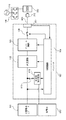
図3は第1実施例の太陽光発電装置の構成例を示すブロック図である。
【0038】
図3において、太陽電池モジュール101により発電された直流電力は、昇圧回路102、インバータ回路103、制御回路104、変圧回路105、開閉器108、出力コネクタ106および系統電圧検出器111を有するインバータにより交流電力に変換される。インバータ107の出力は、分電盤109を介して、系統110に接続される。
【0039】
太陽電池モジュール101としては、三菱電機製の太陽電池モジュールPV-MR140(定格出力140W、19.6V、7.15A)を用いる。太陽電池モジュールは単体で用いてもよいが、太陽電池モジュールを複数接続することで太陽電池アレイを構成してもよい。太陽電池アレイの直並列数は、インバータ107の許容入力電圧や、直流回路の配線の許容電圧や電流に応じて適宜設定すればよい。
【0040】
なお、系統110は、商用電力系統に限らず、工場などの自家交流発電設備などの系統であってもよい。
【0041】
インバータ107が系統に接続される場合、系統電圧検出器111により系統電圧が検出され、系統電圧を示す信号が制御回路104に送られる。制御回路104は、コネクタ106へ系統が接続されず、系統電圧の検出値がほぼ0Vの場合は開閉器108を開状態にする。
【0042】
そして、コネクタ106へ系統が接続されて、200Vの系統電圧が検知されると、制御回路104は、図4に詳細を示す変圧回路105のリレー201に信号を送り、トランス203の二つの二次巻線を直列に接続させた後、適切なタイミングで開閉器108を閉状態にする。この結果、インバータ107は、200Vの交流電力を出力する連系運転モードで動作する。
【0043】
一方、100Vの系統電圧が検出された場合、制御回路104は、リレー201に信号を送り、トランス203の二つの二次巻線を並列に接続させた後、適切なタイミングで開閉器108を閉状態にする。この結果、インバータ107は、100Vの交流電力を出力する連系運転モードで動作する。
【0044】
つまり、制御回路104は、検出される系統電圧に応じて変圧回路105の設定を切り替えるので、インバータ107は、系統電圧に応じて200Vまたは100Vの交流電力を出力する連系運転モードで動作する。なお、制御回路104は、検出される系統電圧に応じて変圧回路105の設定を切り替えるとともに、図示しない過電圧保護回路の検出電圧の設定値も切り替える。
【0045】
また、トランスの利用効率は低下するが、100Vタップを有するトランス203を使用して、系統電圧が200Vの場合は二次巻線の両端から電力を取り出し、100Vの場合は100Vタップから電力を取り出す構成でも構わない。
【0046】
このように、第1実施例のインバータ107は、系統電圧を検出して、系統電圧に応じた電圧の交流電力を出力するので、系統電圧に応じた複数種類のインバータを用意する必要がない。
【0047】
【第2実施例】
図5は第2実施例の太陽光発電装置の構成例を示すブロック図である。第2実施例のインバータ107は、その先端に200V用のプラグ311が付いた出力ケーブルおよび100V用のプラグ312が付いた出力ケーブルを有する。プラグ311および312は、その形状に対応する200V用および100V用の壁コンセント314および313に接続可能である。
【0048】
図6は変圧回路105の構成例を示すブロック図である。図4に示す第1実施例の変圧回路105の構成に、プラグ311および312へ接続されるラインを開閉するためのリレー204および205が追加されている。なお、リレー204および205の接点は、第1実施例の開閉器108の役割も果たす。
【0049】
制御回路104は、プラグ311および312のラインの電圧それぞれを検出する電圧検出器111の検出値がほぼ0Vの場合はリレー204および205をともに開状態にする。
【0050】
そして、プラグ311が対応する壁コンセント314へ接続されて、200Vの系統電圧が検知されると、制御回路104は、リレー201に信号を送り、トランス203の二つの二次巻線を直列に接続させた後、適切なタイミングでリレー204に信号を送りプラグ311へ接続されるラインを閉状態にする。この結果、インバータ107は、200Vの交流電力を出力する連系運転モードで動作する。
【0051】
一方、プラグ312が対応する壁コンセント313へ接続されて、100Vの系統電圧が検出された場合、制御回路104は、リレー201に信号を送り、トランス203の二つの二次巻線を並列に接続された後、適切なタイミングでリレー205に信号を送りプラグ312へ接続されるラインを閉状態にする。この結果、インバータ107は、100Vの交流電力を出力する連系運転モードで動作する。
【0052】
制御回路104は、リレー204または205の一方を駆動してラインを閉状態にした状態で、他方のリレーを駆動することはない。
【0053】
制御回路104は、電流検出器112によりラインに流れる電流を常に監視して、ラインに流れる電流が所定値以下になった場合は直ちにリレー204および205の駆動を解除して、ラインを開状態にする。これは、インバータ107が運転中にプラグ311または312がコンセントから抜かれると、感電などの事故の危険があるからである。
【0054】
あるいは、電圧検出器111によってライン電圧の異常を検知してリレー204および205の駆動を解除して、ラインを開状態にするなど、系統連系型のインバータにおいては「系統連系技術運用ガイドライン」に記述されている保護装置による停電検知機能が働き、安全に停止することができる。
【0055】
また、これらの整定値、整定時間はラインが接続される系統に応じて任意に設定しておく。
【0056】
また、プラグ311および312が同時に壁コンセントへ接続された場合の短絡を防ぐため、さらに未接続のプラグによる感電などの事故を防ぐために、電圧検出器111や電流検出器112は主回路から絶縁しておく必要がある。
【0057】
また、プラグ311および312が同時に壁コンセントへ接続された場合、制御回路104は、200V出力を優先的に設定するが、勿論、100V出力を設定しても構わない。
【0058】
さらに、図には示さないが、インバータ107に自立運転時の出力コンセントを備えてもよい。その場合、停電を検出した制御回路104は、昇圧回路102およびインバータ回路103に対してゲートオフ信号を出力するとともに、リレー204および205の駆動を解除してインバータ107と系統110とを切り離す。その後、インバータ回路103を自立運転モードに切り替えるとともに、ゲートオフ信号を解除する。これにより出力コンセントから交流電力を得ることができるので、災害などで停電した場合でも太陽光発電装置(少なくともインバータ107)を任意の場所に設置して、様々な負荷に交流電力を供給することができる。
【0059】
このように、第2実施例のインバータ107は、第1実施例と同様に、系統電圧を検出して、系統電圧に応じた電圧の交流電力を出力するので、系統電圧に応じた複数種類のインバータを用意する必要がない。さらに、プラグ311または312を介して容易に系統110に接続し連系運転を行うことができる。また、非常時には任意の場所に設置して非常用電源として有効に活用することができる。
【0060】
また、図5には二つのプラグ311および312が接続されている例を示したが、第1実施例と同様に、インバータ107の出力端に出力コネクタ106を設けて、必要なプラグをその先端にもつケーブルだけを接続できるようにしてもよい。このようにすれば、二つのプラグ311および312に接続されるラインごとに電圧および電流を検出する必要がないから、電圧検出器111および電流検出器112は一組で済む。さらに、変圧回路105のリレー204または205の一方が不要になる。
【0061】
【第3実施例】
第3実施例のインバータ107は、その出力端に、図7に示すような、プラグ802が挿入される出力コネクタ(レセプタクル)801を有す。プラグ802の形状はA、B、B3、BF、C、OおよびSEと区別され、太陽光発電装置が使用される地域、あるいは、使用者が所望する電圧に合った形状のプラグ802が使用される。詳細は後述するが、インバータ107は、プラグ802の形状に応じた電圧を出力する。
【0062】
レセプタクル801の底部にはプラグ802の突起806が貫通可能な開口808があり、開口808を貫通した突起806はスイッチ807をオンにする。制御部104は、スイッチ807がオンの場合、例えば200V用のプラグ802が接続されたと判断する。
【0063】
電力用の電極805および804は互いに嵌合可能であり、プラグ802をレセプタクル801へ挿入すると、ケーブル803を介して、インバータ107は系統110に接続される。
【0064】
図8に第3実施例の太陽光発電装置の構成例を示すブロック図である。
【0065】
レセプタクル801に接続されたプラグ802が100V用の場合、制御回路104は、昇圧回路102の出力電圧を第一の目標値(例えば160V)に制御し、インバータ回路103を100V出力の連系運転モードにする。また、プラグ802が200V用の場合、制御回路104は、昇圧回路102の出力電圧を第二の目標電圧(例えば320V)に制御し、インバータ回路103を200V出力の連系運転モードにする。
【0066】
なお、詳細な説明は省略するが、電圧を変更する場合、図1に示すインダクタ5や連系リアクタ(不図示)のインダクタンスを必要に応じて変更する。また、開閉器108の操作は第1実施例と同じである。さらに、図8には示さないが、電圧検出器や電流検出器を備え、プラグ802が示す電圧と系統110の電圧が異なる場合や、プラグ312が抜けた場合に、制御回路104は開閉器108を開状態にする。勿論、電圧の変更に、第1実施例と同様に、変圧回路105を利用しても好い。
【0067】
さらに、図8に示すインバータ107は、夜間や、太陽電池モジュール101が接続できない場合に直流電力を供給するための蓄電池617、蓄電池617の充放電を制御する充放電制御回路618、並びに、太陽電池モジュール101と蓄電池617との接続を開閉する開閉器616を有する。なお、蓄電池617はインバータ107内に配置しても、外に配置してもよい。制御回路104は、自立運転において、夜間や日射が弱い時など、太陽電池モジュール101の出力が所定電圧を超えない場合、太陽電池モジュール101の出力低下を検知すると、開閉器616を閉じ、充放電制御回路618に蓄電池617の電力を供給させる。
【0068】
このように、第4実施例のインバータによれば、インバータ107に接続されるプラグの形状から系統電圧を知ることができ、系統電圧に応じた電圧の交流電力を出力するので、系統電圧に応じた複数種類のインバータを用意する必要がない。さらに、第2実施例と同様に、プラグ311または312を介して容易に系統110に接続し連系運転を行うことができる。また、非常時には蓄電池617とともに、任意の場所に設置して非常用電源として有効に活用することができる。
【0069】
上述した実施形態の太陽光発電装置を用いることにより、以下の効果が期待できる。
(1) 実施形態のインバータは、系統電圧を検知して適切な電圧の交流電力を出力するから、系統連系を容易に行うことができる。
(2) 実施形態のインバータは、系統電圧に応じて例えば100Vまたは200Vの交流電力を出力するから、連系すべき系統電圧に合わせて複数のインバータを製造し用意する必要がない。
(3) 実施形態のインバータは、平常時は系統に連系して使用し、非常時には任意の場所に移動して使用することができるので、非常用電源として有効に活用できる。
(4) 実施形態のインバータは、特別な結線を行わずに、建造物の壁コンセントなどに容易に接続することができ、系統への連系や非常時の電力供給を容易に行うことができる。さらに、壁コンセントからプラグが抜けた場合や、不適切な接続が行われた場合でも安全を考慮した動作を行うことができる。
【0070】
なお、上記では、系統電圧が100Vおよび200Vの場合について記述したが、さその他、様々な地域の様々な系統電圧にも対応可能である。
【0071】
また、詳細は説明しないが、非常用電源として実施形態の太陽光発電装置やインバータを利用する場合は、系統電圧が存在しないなどの理由でインバータの出力開閉器が閉状態にならない場合がある。そのような場合を考慮して、制御回路104の動作を非常用電源動作モードに切り替えるスイッチを備えるのが望ましい。このスイッチにより、例えば「正常時」「非常時100V出力」「非常時200V出力」などの動作モードを設定できるようにする。
【0072】
さらに、通常時は、壁コンセントからプラグが抜けた場合などを考慮して、出力電流が所定値以下になるとインバータの出力開閉器を開状態にするが、非常時は負荷の変動を考慮して、出力開閉器を開状態にする出力電流値を下げるなどの対応を行う。
【0073】
【発明の効果】
【0074】
本発明によれば、電力系統へ連系され、電力系統へ交流電力を供給する電力変換装置を100Vおよび200Vの系統電圧に対応させ、系統電圧に応じて電力変換装置の出力電圧を設定することができる。
【図面の簡単な説明】
【図1】昇圧チョッパ回路の一例を示す図、
【図2】制御回路の構成例を示すブロック図、
【図3】第1実施例の太陽光発電装置の構成例を示すブロック図、
【図4】第1実施例の変圧回路の詳細な構成例を示すブロック図、
【図5】第2実施例の太陽光発電装置の構成例を示すブロック図、
【図6】第2実施例の変圧回路の詳細な構成例を示すブロック図、
【図7】第3実施例のインバータの出力端の出力コネクタ(レセプタクル)を説明する図、
【図8】第3実施例の太陽光発電装置の構成例を示すブロック図である。[0001]
BACKGROUND OF THE INVENTION
The present invention is interconnection to the power system, a power conversion apparatus and power generation apparatus that to supply AC power to the power system.
[0002]
[Prior art]
In recent years, DC power generated by solar cells has been converted into AC power by an inverter due to efforts to address environmental issues, etc., and the AC power is converted into household load (hereinafter simply referred to as “load”) and / or commercial power. Many photovoltaic power generation devices that supply a system (hereinafter simply referred to as “system”) are installed.
[0003]
These photovoltaic power generation devices are also attracting attention as emergency power sources in the event of disasters such as earthquakes. Recently, in the event of a power failure due to an earthquake, system failure, maintenance, etc., there are many solar power generation devices that can be disconnected from the system and operated independently to supply power to the load.
[0004]
In addition, a small inverter called a MIC (Module Integrated Converter) that converts DC power generated by a solar cell into AC power can be attached to the back surface of the solar cell module, enabling output of AC power from a single solar cell module. AC modules are attracting attention as small and medium-sized photovoltaic power generation devices and emergency power supplies.
[0005]
As disclosed in Japanese Patent Laid-Open No. 10-14111, the AC module is connected to a single-phase three-wire neutral line and one power line, and is connected to the system. In a solar power generation apparatus using an AC module, in an emergency, DC power stored in a storage battery is converted into AC power by an emergency inverter and used.
[0006]
[Problems to be solved by the invention]
The AC module is connected to the building grid via a distribution board. In Japan, the voltage of the grid in the building is 100V or 200V, so the AC module also needs to select 100V or 200V output depending on the connection. Therefore, AC module manufacturers need to prepare two types of 100V and 200V outputs when supplying them to Japan. If foreign countries are included, AC module manufacturers can manufacture AC modules that can handle a wider variety of system voltages. There must be.
[0007]
An object of the present invention is to associate a power converter connected to a power system and supply AC power to the power system with a system voltage of 100 V and 200 V, and to set an output voltage of the power converter according to the system voltage. And
[0010]
[Means for Solving the Problems]
The present invention has the following configuration as one means for achieving the above object.
[0011]
Power converter of the present invention is interconnection to the power system, a power converter that to supply AC power to the power system, a conversion circuit for converting DC power to AC power, the output of the converter circuit a transformer for transforming electrical power, and switch to open and close the connection between said transformer said electric power system, a detector for detecting a system voltage of the electric power system, based on the connection state of the power system and the power converter , have a control means for controlling the opening and closing of the transformer ratio and the switch of the transformer, wherein, when the detected value of the system voltage of 200V with a series of secondary winding of the transformer After the connection state, the switch is changed from the open state to the closed state, and when the detected value of the system voltage is 100 V, the secondary winding of the transformer is set in a parallel connection state, and then the switch is opened. It is characterized by changing from a state to a closed state .
[0013]
Further, the interconnection to the power system, a power converter that to supply AC power to the power system, a conversion circuit for converting DC power to AC power, a transformer for transforming the output power of the converter circuit a plurality of connection means different types to be used in the electric power system of connection between the power converter, and a plurality of switches for opening and closing respective connections of said plurality of connecting means and said transformer, said power converter determine the type of connection means used to connect the electric power system, based on the determination, have a control means for controlling the opening and closing of the transformer ratio and the switch of the transformer, the control means, 200V When it is determined that the connection means for use is used for connection to the power system, the secondary winding of the transformer is placed in series connection, and then the switch connected to the connection means for 200 V is opened. Connection from 100V to closed state If it is determined that the stage is used for connection to the power system, the secondary winding of the transformer is placed in parallel connection, and then the switch connected to the connection means for 100V is closed from the open state. It is characterized by being in a state .
[0015]
The power generator according to the present invention uses the above power converter.
[0016]
DETAILED DESCRIPTION OF THE INVENTION
Hereinafter, a solar power generation device according to an embodiment of the present invention will be described in detail with reference to the drawings.
[0017]
[Solar cell]
Although the solar cell used in the embodiment is not particularly limited, single crystal silicon solar cells, polycrystalline silicon solar cells, amorphous silicon solar cells and the like are used as photovoltaic elements of silicon semiconductors, and III as the photovoltaic elements of compound semiconductors. -V group compound solar cells, II-VI group compound solar cells, and I-III-VI group compound solar cells can be used.
[0018]
A desired number of solar cells are connected in series and parallel, arranged between a surface protection member such as glass or a weather-resistant film and a back surface reinforcing material such as a moisture-proof protective sheet or a metal steel plate, fixed by a filler, and solar A battery module is formed.
[0019]
In many cases, the solar cell module has an output cable structure in which a terminal box for taking out electric power on a non-light-receiving surface or an output cable having a waterproof connector at the tip thereof is attached. A solar cell array can be configured by connecting a plurality of solar cell modules by connecting terminal boxes using an output cable or by connecting waterproof connectors to each other.
[0020]
In the present embodiment, an inverter that converts DC power output from the solar cell module into AC power is attached to the back surface of the solar cell module, or is electrically and / or mechanically connected to a terminal box. It can also be applied to modules.
[0021]
[Boost circuit]
A booster circuit is a circuit that boosts the voltage of DC power output from a DC power source such as a solar battery to a voltage required by an inverter circuit, and uses a booster chopper circuit, a voltage doubler rectifier circuit, a series-parallel chopper circuit, etc. Can do.
[0022]
FIG. 1 is a diagram illustrating an example of a boost chopper circuit.
[0023]
By turning the switching element 2 on and off, the capacitor 5 is charged via the diode 4 with the sum of the input voltage Vi and the voltage induced in the coil 3, whereby an output voltage Vo higher than the input voltage Vi is obtained. IGBT, MOSFET, etc. are used for the switching element 2.
[0024]
The output voltage Vo of the booster circuit is determined according to the ON / OFF ratio (duty ratio) of the gate signal S input from the
[0025]
[Inverter circuit]
As the inverter circuit, a voltage type inverter using IGBT or MOSFET as a switching element is preferable. The
[0026]
[Control circuit]
FIG. 2 is a block diagram illustrating a configuration example of the
[0027]
In FIG. 2, the
[0028]
The PWM
[0029]
The frequency /
[0030]
The
[0031]
The
[0032]
The switching
[0033]
As described above, the
[0034]
The target value of the output voltage may be set in the
[0035]
[Switch]
An electromagnetic switch, a breaker, etc. can be used for the switch installed in the distribution board etc. which are arrange | positioned between an output terminal of an inverter and a solar power generation device, and between an output terminal and a system | strain. In the case of an electromagnetic switch, for example, the switching operation is performed according to a signal input from the
[0036]
[Voltage / current detector]
The voltage / current detector is not particularly limited, but a shunt resistor or a current transformer is used as the current detector. The terminal voltage of the shunt resistor and the output voltage of the current transformer are A / D converted and input to the
[0037]
[First embodiment]
FIG. 3 is a block diagram illustrating a configuration example of the solar power generation device according to the first embodiment.
[0038]
In FIG. 3, the DC power generated by the
[0039]
As the
[0040]
The
[0041]
When the
[0042]
When the system is connected to the
[0043]
On the other hand, if the system voltage of 100V is detected, the
[0044]
That is, since the
[0045]
Also, although the transformer utilization efficiency is reduced, the
[0046]
As described above, the
[0047]
[Second embodiment]
FIG. 5 is a block diagram showing a configuration example of the photovoltaic power generation apparatus according to the second embodiment. The
[0048]
FIG. 6 is a block diagram illustrating a configuration example of the
[0049]
The
[0050]
When the
[0051]
On the other hand, when the
[0052]
The
[0053]
The
[0054]
Or, if the abnormality of the line voltage is detected by the
[0055]
These settling values and settling times are arbitrarily set according to the system to which the line is connected.
[0056]
In order to prevent short circuit when plugs 311 and 312 are connected to a wall outlet at the same time, and to prevent accidents such as electric shock due to unconnected plugs,
[0057]
When the
[0058]
Further, although not shown in the figure, the
[0059]
As described above, the
[0060]
FIG. 5 shows an example in which two
[0061]
[Third embodiment]
The
[0062]
An
[0063]
The
[0064]
FIG. 8 is a block diagram illustrating a configuration example of the solar power generation device according to the third embodiment.
[0065]
When the
[0066]
Although detailed description is omitted, when the voltage is changed, the inductance of the inductor 5 and the interconnected reactor (not shown) shown in FIG. 1 is changed as necessary. The operation of the
[0067]
Further, the
[0068]
Thus, according to the inverter of the fourth embodiment, the system voltage can be known from the shape of the plug connected to the
[0069]
By using the solar power generation device of the above-described embodiment, the following effects can be expected.
(1) Since the inverter of the embodiment detects the system voltage and outputs AC power having an appropriate voltage, the system interconnection can be easily performed.
(2) Since the inverter according to the embodiment outputs, for example, 100V or 200V AC power according to the system voltage, there is no need to manufacture and prepare a plurality of inverters according to the system voltage to be connected.
(3) The inverter of the embodiment can be used effectively as an emergency power source because it can be used in a normal state and connected to a system, and can be moved to an arbitrary place in an emergency.
(4) The inverter according to the embodiment can be easily connected to a wall outlet of a building without special connection, and can be easily connected to the system or supplied with emergency power. . Furthermore, even when the plug is disconnected from the wall outlet or an inappropriate connection is made, it is possible to perform an operation in consideration of safety.
[0070]
In the above description, the case where the system voltage is 100 V and 200 V has been described, but various other system voltages in various regions can be dealt with.
[0071]
Although not described in detail, when the photovoltaic power generation apparatus or the inverter according to the embodiment is used as an emergency power supply, the output switch of the inverter may not be closed because the system voltage does not exist. In consideration of such a case, it is desirable to provide a switch for switching the operation of the
[0072]
In addition, in normal times, the output switch of the inverter is opened when the output current falls below a predetermined value, taking into account the case where the plug is removed from the wall outlet. Measures such as lowering the output current value to open the output switch.
[0073]
【The invention's effect】
[0074]
According to the present invention, the power converter connected to the power system and supplying AC power to the power system is made to correspond to the system voltage of 100V and 200V, and the output voltage of the power converter is set according to the system voltage. Can do.
[Brief description of the drawings]
FIG. 1 is a diagram showing an example of a boost chopper circuit;
FIG. 2 is a block diagram illustrating a configuration example of a control circuit;
FIG. 3 is a block diagram illustrating a configuration example of the solar power generation device according to the first embodiment;
FIG. 4 is a block diagram showing a detailed configuration example of the transformer circuit of the first embodiment;
FIG. 5 is a block diagram illustrating a configuration example of the solar power generation device according to the second embodiment;
FIG. 6 is a block diagram showing a detailed configuration example of the transformer circuit of the second embodiment;
FIG. 7 is a diagram for explaining an output connector (receptacle) at the output end of the inverter according to the third embodiment;
FIG. 8 is a block diagram illustrating a configuration example of a photovoltaic power generation apparatus according to a third embodiment.
Claims (7)
直流電力を交流電力に変換する変換回路と、
前記変換回路の出力電力を変圧する変圧器と、
前記変圧器と前記電力系統の接続を開閉する開閉器と、
前記電力系統の系統電圧を検出する検出器と、
前記電力変換装置と前記電力系統の接続状態に基づき、前記変圧器の変圧比および前記開閉器の開閉を制御する制御手段とを有し、
前記制御手段は、前記系統電圧の検出値が200Vの場合は、前記変圧器の二次巻線を直列接続状態にした後、前記開閉器を開状態から閉状態にし、前記系統電圧の検出値が100Vの場合は、前記変圧器の二次巻線を並列接続状態にした後、前記開閉器を開状態から閉状態にすることを特徴とする電力変換装置。A power converter that is connected to a power system and supplies AC power to the power system,
A conversion circuit for converting DC power to AC power;
A transformer for transforming the output power of the conversion circuit;
A switch that opens and closes the connection between the transformer and the power system;
A detector for detecting a system voltage of the power system;
Based on the connection state of the power converter and the power system, it has a control means for controlling the transformation ratio of the transformer and the opening and closing of the switch,
When the detected value of the system voltage is 200 V, the control means sets the secondary winding of the transformer in a serial connection state, then changes the switch from an open state to a closed state, and detects the detected value of the system voltage. Is 100V, the secondary winding of the transformer is put in a parallel connection state, and then the switch is changed from an open state to a closed state.
直流電力を交流電力に変換する変換回路と、
前記変換回路の出力電力を変圧する変圧器と、
前記電力変換装置と前記電力系統の接続に使用される種類が異なる複数の接続手段と、
前記変圧器と前記複数の接続手段の接続をそれぞれ開閉する複数の開閉器と、
前記電力変換装置と前記電力系統の接続に使用される接続手段の種類を判断し、前記判断に基づき、前記変圧器の変圧比および前記開閉器の開閉を制御する制御手段とを有し、
前記制御手段は、200V用の接続手段が前記電力系統との接続に使用されたと判断した場合は、前記変圧器の二次巻線を直列接続状態にした後、前記200V用の接続手段に接続された開閉器を開状態から閉状態にし、100V用の接続手段が前記電力系統との接続に使用されたと判断した場合は、前記変圧器の二次巻線を並列接続状態にした後、前記100V用の接続手段に接続された開閉器を開状態から閉状態にすることを特徴とする電力変換装置。A power converter that is connected to a power system and supplies AC power to the power system,
A conversion circuit for converting DC power to AC power;
A transformer for transforming the output power of the conversion circuit;
A plurality of connection means of different types used to connect the power converter and the power system,
A plurality of switches each for opening and closing the connection of the transformer and the plurality of connection means;
Determining the type of connection means used to connect the power converter and the power system, and based on the determination, control means for controlling the transformation ratio of the transformer and the opening and closing of the switch;
When the control means determines that the connection means for 200V is used for connection to the power system, the secondary winding of the transformer is connected in series, and then connected to the connection means for 200V. When it is determined that the connection means for 100V is used for connection with the power system, after the secondary winding of the transformer is connected in parallel, A power converter characterized in that a switch connected to a connection means for 100 V is changed from an open state to a closed state.
Priority Applications (4)
| Application Number | Priority Date | Filing Date | Title |
|---|---|---|---|
| JP2000299974A JP4405654B2 (en) | 2000-09-29 | 2000-09-29 | Power converter and power generator |
| US09/963,569 US7733069B2 (en) | 2000-09-29 | 2001-09-27 | Power converting apparatus and power generating apparatus |
| EP01123526A EP1198056A3 (en) | 2000-09-29 | 2001-09-28 | Power converting apparatus and power generating apparatus |
| US10/760,353 US7177168B2 (en) | 2000-09-29 | 2004-01-21 | Power converting apparatus and power generating apparatus |
Applications Claiming Priority (1)
| Application Number | Priority Date | Filing Date | Title |
|---|---|---|---|
| JP2000299974A JP4405654B2 (en) | 2000-09-29 | 2000-09-29 | Power converter and power generator |
Publications (3)
| Publication Number | Publication Date |
|---|---|
| JP2002112461A JP2002112461A (en) | 2002-04-12 |
| JP2002112461A5 JP2002112461A5 (en) | 2007-11-15 |
| JP4405654B2 true JP4405654B2 (en) | 2010-01-27 |
Family
ID=18781708
Family Applications (1)
| Application Number | Title | Priority Date | Filing Date |
|---|---|---|---|
| JP2000299974A Expired - Fee Related JP4405654B2 (en) | 2000-09-29 | 2000-09-29 | Power converter and power generator |
Country Status (1)
| Country | Link |
|---|---|
| JP (1) | JP4405654B2 (en) |
Cited By (1)
| Publication number | Priority date | Publication date | Assignee | Title |
|---|---|---|---|---|
| KR101889772B1 (en) * | 2016-08-26 | 2018-09-20 | 엘지전자 주식회사 | Photovoltaic module and photovoltaic system including the same |
Families Citing this family (10)
| Publication number | Priority date | Publication date | Assignee | Title |
|---|---|---|---|---|
| JP2005057943A (en) * | 2003-08-07 | 2005-03-03 | Omron Corp | Interconnection device and setting device therefor, and set value setting method thereof |
| WO2005029657A1 (en) * | 2003-09-19 | 2005-03-31 | The Furukawa Electric Co., Ltd. | Solar cell module and its element |
| WO2010106799A1 (en) * | 2009-03-18 | 2010-09-23 | 富士電機システムズ株式会社 | Solar cell module |
| JP5552024B2 (en) * | 2010-10-28 | 2014-07-16 | パナソニック株式会社 | Electric vehicle charger |
| JP5311153B2 (en) | 2011-03-15 | 2013-10-09 | オムロン株式会社 | Power control apparatus and power control method |
| JP5858356B2 (en) * | 2011-10-24 | 2016-02-10 | 株式会社ヒューズクリエーション | Solar power generation system |
| KR101311529B1 (en) | 2012-03-29 | 2013-09-25 | 홍선표 | Power generation apparatus using current transformer |
| CN109449995B (en) * | 2018-12-29 | 2023-07-21 | 北京天诚同创电气有限公司 | Method and system for controlling braking loop of wind power converter |
| JP7185597B2 (en) * | 2019-06-26 | 2022-12-07 | ニチコン株式会社 | Power storage device and power storage system including the power storage device |
| DE102021122282A1 (en) * | 2021-08-26 | 2023-03-02 | Olympus Winter & Ibe Gmbh | Electrosurgical generator with multilevel inverter for HF high voltage |
-
2000
- 2000-09-29 JP JP2000299974A patent/JP4405654B2/en not_active Expired - Fee Related
Cited By (1)
| Publication number | Priority date | Publication date | Assignee | Title |
|---|---|---|---|---|
| KR101889772B1 (en) * | 2016-08-26 | 2018-09-20 | 엘지전자 주식회사 | Photovoltaic module and photovoltaic system including the same |
Also Published As
| Publication number | Publication date |
|---|---|
| JP2002112461A (en) | 2002-04-12 |
Similar Documents
| Publication | Publication Date | Title |
|---|---|---|
| US7177168B2 (en) | Power converting apparatus and power generating apparatus | |
| US11316471B2 (en) | Manual transfer switch for onsite energy generation and storage systems | |
| US8890363B2 (en) | Automatic system for synchronous enablement-disablement of solar photovoltaic panels of an energy production plant with distributed DC/DC conversion | |
| US5977659A (en) | Inverter apparatus and solar power generation apparatus | |
| JP5127001B2 (en) | Device for supplying electrical energy to a power supply network and DC voltage transformer used in said device | |
| US8116103B2 (en) | Device for feeding electric energy into a power grid and DC converter for such a device | |
| KR101029163B1 (en) | Inverter for feeding elecric energy into a power supply system | |
| US10797485B2 (en) | Power conditioner, power supply system, and current control method | |
| US20150375628A1 (en) | Multi-directional converter comprising three ports and a single transformer for electric vehicles | |
| JPH06133556A (en) | Inverter for system interconnection | |
| AU2001284979A1 (en) | High efficiency fuel cell power conditioner | |
| CN102355042A (en) | Super-capacitor-based direct current power device of power station and power supply method thereof | |
| JP2017135889A (en) | Power conversion device, and power conversion system | |
| JP4405654B2 (en) | Power converter and power generator | |
| JP6043967B2 (en) | Power storage system and grid interconnection system using the same | |
| JP5211772B2 (en) | Power conditioner operation control device and photovoltaic power generation system | |
| CN113647005A (en) | Isolation converter | |
| US20190028023A1 (en) | Distribution transformer interface apparatus and methods | |
| US20080084645A1 (en) | Emergency solar power supply | |
| JPH1014128A (en) | System linked power source system and power source system | |
| US11070079B2 (en) | Integrated power supply system for auxiliary services for power converters | |
| EP3487034B1 (en) | Power conversion system, power supply system, and power conversion apparatus | |
| JP3633123B2 (en) | Distributed power system | |
| JP2014054116A (en) | Electrical power system | |
| JPH11225448A (en) | Solar power generation system and operation thereof |
Legal Events
| Date | Code | Title | Description |
|---|---|---|---|
| A521 | Request for written amendment filed |
Free format text: JAPANESE INTERMEDIATE CODE: A523 Effective date: 20071001 |
|
| A621 | Written request for application examination |
Free format text: JAPANESE INTERMEDIATE CODE: A621 Effective date: 20071001 |
|
| RD03 | Notification of appointment of power of attorney |
Free format text: JAPANESE INTERMEDIATE CODE: A7423 Effective date: 20071001 |
|
| RD04 | Notification of resignation of power of attorney |
Free format text: JAPANESE INTERMEDIATE CODE: A7424 Effective date: 20080822 |
|
| A977 | Report on retrieval |
Free format text: JAPANESE INTERMEDIATE CODE: A971007 Effective date: 20090223 |
|
| A131 | Notification of reasons for refusal |
Free format text: JAPANESE INTERMEDIATE CODE: A131 Effective date: 20090302 |
|
| A521 | Request for written amendment filed |
Free format text: JAPANESE INTERMEDIATE CODE: A523 Effective date: 20090430 |
|
| A131 | Notification of reasons for refusal |
Free format text: JAPANESE INTERMEDIATE CODE: A131 Effective date: 20090525 |
|
| A521 | Request for written amendment filed |
Free format text: JAPANESE INTERMEDIATE CODE: A523 Effective date: 20090724 |
|
| A131 | Notification of reasons for refusal |
Free format text: JAPANESE INTERMEDIATE CODE: A131 Effective date: 20090817 |
|
| A521 | Request for written amendment filed |
Free format text: JAPANESE INTERMEDIATE CODE: A523 Effective date: 20091013 |
|
| TRDD | Decision of grant or rejection written | ||
| A01 | Written decision to grant a patent or to grant a registration (utility model) |
Free format text: JAPANESE INTERMEDIATE CODE: A01 Effective date: 20091102 |
|
| A01 | Written decision to grant a patent or to grant a registration (utility model) |
Free format text: JAPANESE INTERMEDIATE CODE: A01 |
|
| A61 | First payment of annual fees (during grant procedure) |
Free format text: JAPANESE INTERMEDIATE CODE: A61 Effective date: 20091105 |
|
| FPAY | Renewal fee payment (event date is renewal date of database) |
Free format text: PAYMENT UNTIL: 20121113 Year of fee payment: 3 |
|
| R150 | Certificate of patent or registration of utility model |
Free format text: JAPANESE INTERMEDIATE CODE: R150 |
|
| FPAY | Renewal fee payment (event date is renewal date of database) |
Free format text: PAYMENT UNTIL: 20131113 Year of fee payment: 4 |
|
| LAPS | Cancellation because of no payment of annual fees |