JP4399059B2 - Thin film structure - Google Patents
Thin film structure Download PDFInfo
- Publication number
- JP4399059B2 JP4399059B2 JP25588699A JP25588699A JP4399059B2 JP 4399059 B2 JP4399059 B2 JP 4399059B2 JP 25588699 A JP25588699 A JP 25588699A JP 25588699 A JP25588699 A JP 25588699A JP 4399059 B2 JP4399059 B2 JP 4399059B2
- Authority
- JP
- Japan
- Prior art keywords
- thin film
- buffer layer
- single crystal
- epitaxial
- film structure
- Prior art date
- Legal status (The legal status is an assumption and is not a legal conclusion. Google has not performed a legal analysis and makes no representation as to the accuracy of the status listed.)
- Expired - Fee Related
Links
Images


Landscapes
- Optical Integrated Circuits (AREA)
- Crystals, And After-Treatments Of Crystals (AREA)
- Non-Insulated Conductors (AREA)
Description
【0001】
【発明の属する技術分野】
本発明は、単結晶基板の表面に形成される薄膜構造体とその製造方法に関し、詳しくは、光スイッチ、光変調素子、光偏向素子、第二高調波素子などのエピタキシャル薄膜光導波路、あるいは不揮発性メモリ、FETなどのエピタキシャル薄膜を設けるための導電性基板として利用可能な、薄膜構造体とその製造方法に関する。
【0002】
【従来の技術】
Pb1-xLax(ZryTi1-y)1-x/4O3(PLZT)系材料は、良好な電気光学効果を有する酸化物強誘電体材料のなかでも、極めて大きな電気光学係数を有し、一次の電気光学係数を示す組成ではLiNbO3の値を一桁以上うわ回り、二次の電気光学係数を示す組成では強誘電体材料のなかで最大レベルの値を有することがG. H. Haertling and C. E. Land, J. Amer. Ceram. Soc. Vol.54. p.1 (1971).などに報告されており、その光デバイスへの応用が期待されている。
【0003】
本発明者等は、不純物をドープしたSrTiO3基板には、均一なペロブスカイト相を有するPLZT薄膜をエピタキシャル成長することが可能であり、この基板上に形成したPLZT薄膜が優れた特性を示すことを見出し、すでに出願している(特願平10−157609号)。
【0004】
しかしながら、不純物をドープしたSrTiO3では、1インチ程度のサイズの基板しか製造することができず、基板サイズが限られるために応用範囲も限られる。また、不純物をドープしたSrTiO3は、へき開性がないために、PLZT薄膜を設けても光導波路素子として利用するためには端面を機械的に研磨しなけらばならず、工程が複雑で多くの作製時間を要することになる。
【0005】
【発明が解決しようとする課題】
本発明者等は、PLZT材料の応用範囲を広げると共に、PLZT材料を用いた光導波路素子をより簡易な方法で製造するために、ABO3型のペロブスカイト相構造を有し、PLZT薄膜等をエピタキシャル成長することが可能な導電性薄膜を、サファイア基板やMgO基板等の汎用基板上に形成することを検討している。
【0006】
数インチのサイズの基板が成長可能なサファイアなどの基板上へ、均一なペロブスカイト相を有する導電性薄膜をエピタキシャル成長させることができれば、広範囲な応用をひらくことが可能となる。また、サファイア基板やMgO基板またはMgOをバッファ層としたGaAs基板やSi基板等のへき開性を有する基板へ導電性薄膜を介してPLZT薄膜をエピタキシャル成長させることができれば、へき開によって容易に端面を形成することが可能となり、大幅なコスト低減を図ることが可能である。また、サファイア基板やMgO基板またはMgOをバッファ層としたGaAs基板やSi基板へ、導電性薄膜を介してPLZT薄膜をエピタキシャル成長させることができれば、半導体デバイスとのモノリシック集積化が可能となる。
【0007】
しかしながら、サファイア基板やMgO基板等はABO3型のペロブスカイト相構造を有しておらず、これらの単結晶基板上へ、単一の配向を有し、かつ均一なペロブスカイト相構造を有する導電性の薄膜をエピタキシャル成長させることは極めて困難であった。
【0008】
従って、本発明の目的は、単結晶基板の表面に形成される薄膜構造体であって、単結晶状またはエピタキシャル状でありABO3型ペロブスカイト相構造を有する導電性または半導電性の薄膜を表面に有する薄膜構造体とその製造方法を提供することある。
【0009】
【課題を解決するための手段】
上記目的を達成するために、参考例に係る薄膜構造体は、単結晶基板の表面に形成される薄膜構造体であって、該単結晶基板の表面に設けられた単結晶状またはエピタキシャル状のPb1-xLax(ZryTi1-y)1-x/4O3からなるバッファ層と、該バッファ層の表面に設けられた単結晶状またはエピタキシャル状でありABO3型ペロブスカイト相構造を有する導電性または半導電性の薄膜と、からなることを特徴とする。
【0010】
また、参考例に係る薄膜構造体の製造方法は、単結晶基板の表面に形成される薄膜構造体の製造方法であって、該単結晶基板の表面に、単結晶状またはエピタキシャル状のPb1-xLax(ZryTi1-y)1-x/4O3からなるバッファ層を形成した後、該バッファ層の表面に、単結晶状またはエピタキシャル状でありABO3型ペロブスカイト相構造を有する導電性または半導電性の薄膜を形成することを特徴とする。
【0011】
NbドープSrTiO3、LaドープSrTiO3、BaPbO3、SrRuO3、YBa2Cu3O7-x、SrVO3、LaNiO3、La0.5Sr0.5CoO3などの導電性または半導電性の材料は、非ペロブスカイト表面には、ABO3型ペロブスカイト相構造のエピタキシャル薄膜は成長させにくく、成長後の薄膜は結晶性が悪く、非ペロブスカイト相が混入し易い。
【0012】
参考例に係る発明では、単結晶状またはエピタキシャル状のPb1-xLax(ZryTi1-y)1-x/4O3からなるバッファ層は、ペロブスカイト相構造を有し、このバッファ層を介して導電性または半導電性のエピタキシャル薄膜を形成することで、単結晶基板上に、ABO3型ペロブスカイト相構造の導電性または半導電性のエピタキシャル薄膜を設けることが可能になる。
【0013】
単結晶状またはエピタキシャル状でありABO3型ペロブスカイト相構造を有する導電性または半導電性の薄膜としては、SrRuO3からなる薄膜が特に好ましい。
【0014】
また、バッファ層の形成には、金属有機化合物溶液の塗布を用いた固相エピタキシャル成長が平坦化特性が良好であるため、最も望ましい成長方法である。
【0015】
そして、請求項1に記載の薄膜構造体は、参考例に係る発明において、前記バッファ層が、0<x<0.30、0<y<0.20の範囲の単結晶状またはエピタキシャル状のPb1-xLax(ZryTi1-y)1-x/4O3からなる第1バッファ層と、該第1バッファ層の表面に設けられた0<x<0.20、0.20<y<1.0の範囲の単結晶状またはエピタキシャル状のPb1-xLax(ZryTi1-y)1-x/4O3からなる第2バッファ層と、によって構成されることを特徴とする。
【0016】
また、請求項7に記載の薄膜構造体の製造方法は、単結晶基板の表面に形成される薄膜構造体の製造方法であって、該単結晶基板の表面に、0<x<0.30、0<y<0.20の範囲の単結晶状またはエピタキシャル状のPb1-xLax(ZryTi1-y)1-x/4O3からなる第1バッファ層を形成し、該第1バッファ層の表面に、0<x<0.20、0.20<y<1.0の範囲の単結晶状またはエピタキシャル状のPb1-xLax(ZryTi1-y)1-x/4O3からなる第2バッファ層を形成し、該第2バッファ層の表面に、単結晶状またはエピタキシャル状でありABO3型ペロブスカイト相構造を有する導電性または半導電性の薄膜を形成することを特徴とする。
【0017】
第1バッファ層を構成する0<x<0.30、0<y<0.20の範囲の組成のPLZTは、パイロクロア層が形成しにくく、ぺロブスカイト単一相のエピタキシャル成長が容易に行える。次に、この第1バッファ層の表面に、0<x<0.20、0.20<y<1.0の範囲の組成のPLZTからなる第2バッファ層をエピタキシャル成長させると、第2バッファ層は、同様の結晶構造と組成を有する第1バッファ層の表面に成長するため、通常はぺロブスカイト単一相の成長が困難な組成であるが、パイロクロア層の生成なしにぺロブスカイト単一相としてのエピタキシャル成長が可能となる。得られた第2バッファ層は、ペロブスカイト相構造を有するため、この第2バッファ層を介して、ABO3型ペロブスカイト相構造の導電性または半導電性のエピタキシャル薄膜を設けることが可能になる。
【0018】
また、第1バッファ層を構成する0<x<0.30、0<y<0.20の範囲の組成のPLZTは、図9に示すように結晶粒界に深い溝が形成し易いので、第1バッファ層の膜厚を1〜40nmの範囲とし、図10のように結晶粒が島状に分離した形態とすることが好ましい。
【0019】
第1バッファ層の結晶粒が島状に分離した形態であるため、この第1バッファ層の表面に第2バッファ層をエピタキシャル成長させると、島間に空隙を作らずにギャップを埋めることが可能となり、第2バッファ層の表面は平滑になる。また、得られた第2バッファ層は、ペロブスカイト相構造を有し、かつ良好な結晶性と平滑性を有するため、この第2バッファ層を介して導電性または半導電性のエピタキシャル薄膜を形成することで、より良好な品質のABO3型ペロブスカイト相構造の導電性または半導電性のエピタキシャル薄膜を形成することが可能になる。
【0020】
なお、本発明において「単結晶状」とは、一般に「エピタキシャル」と呼ばれているものであり、単結晶をそのまま薄膜化した無欠陥のものから、双晶などの結晶欠陥が含まれるものまでを含むが、少なくともθ−2θX線回折パターンによって結晶方位が一方向に単一配向している、すなわちランダム配向面が単一配向面の回折強度の1%以下であると同定されるものを指す。
【0021】
【発明の実施の形態】
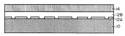
参考例の薄膜構造体は、図1に示す通り、単結晶基板10の表面に設けられた単結晶状またはエピタキシャル状のPb1-xLax(ZryTi1-y)1-x/4O3からなるバッファ層12と、該バッファ層12の表面に設けられた単結晶状またはエピタキシャル状でありABO3型ペロブスカイト相構造を有する導電性または半導電性の薄膜14と、から構成される。以下、製造工程に従い、参考例と共に、本発明の薄膜構造体について詳細に説明する。
【0022】
単結晶基板10の材料としては、ZrO2、Y2O38%−ZrO2、MgO、MgAl2O4、Al2O3、ZnO、ZnGa2O4、CdGa2O4、CdGa2O4、Mg2TiO4、MgTi2O4、SrTiO3、BaTiO3、BaZrO3、LaAlO3、LiNbO3、LiTaO3などの酸化物、およびこれらの酸化物を表面に設けたSi,Ge,ダイアモンドなどの単体半導体、AlAs,AlSb,AlP,GaAs,GaSb,InP,InAs,InSb,AlGaP,AlLnP,AlGaAs,AlInAs,AlAsSb,GaInAs,GaInSb,GaAsSb,InAsSbなどのIII-V系の化合物半導体、ZnS,ZnSe,ZnTe,CaSe,CdTe,HgSe,HgTe,CdSなどのII-VI系の化合物半導体が挙げられる。この中でも、大きな基板が入手可能なAl2O3、MgO、MgOを表面に設けたSi、MgOを表面に設けたGaAsがより好ましい。
【0023】
まず、前記単結晶基板10の表面にバッファ層12を設ける。
【0024】
バッファ層12は、単結晶状またはエピタキシャル状のPb1-xLax(ZryTi1-y)1-x/4O3である。バッファ層を1層構成とする場合、平滑性の高い表面を形成することができる点で、0<x<0.3、0.1<y<0.6の範囲のエピタキシャルPb1-xLax(ZryTi1-y)1-x/4O3(PLZT)を用いるのが好ましい。
【0025】
そして、本発明の薄膜構造体、図2に示すように、バッファ層を第1バッファ層12Aと第2バッファ層12Bの2層構成である。
【0026】
バッファ層を2層構成とする場合、第1バッファ層12Aには、図3に領域Aで示す0<x<0.30、0<y<0.20の範囲のエピタキシャルPb1-xLax(ZryTi1-y)1-x/4O3(PLZT)を用い、第2バッファ層12Bには、図3に領域Bで示す0<x<0.20、0.20<y<1.0の範囲のエピタキシャルPb1-xLax(ZryTi1-y)1-x/4O3(PLZT)を用いる。また、表面平滑化の観点から、第1バッファ層12Aの膜厚を1〜40nmの範囲とするのが好ましい。
【0027】
バッファ層12は、電子ビーム蒸着、フラッシュ蒸着、イオン・プレーティング、Rf−マグネトロン・スパッタリング、イオン・ビーム・スパッタリング、レーザー・アブレーション、MBE、CVD、プラズマCVD、MOCVDなどの気相エピタキシャル成長法、およびゾルゲル法、MOD法などのウエット・プロセスによる固相エピタキシャル成長法より選ばれるエピタキシャル成長方法により、単結晶基板10上に形成することが可能であるが、本発明のバッファ層の形成には、金属有機化合物から得られた強誘電体前駆体溶液を塗布して薄膜を形成する塗布工程、該薄膜を熱分解する熱分解工程、及び熱分解後の薄膜を結晶成長温度まで昇温して固相エピタキシャル成長させる結晶成長工程を、単数回または複数回行う、固相エピタキシャル成長法が特に好ましい。金属有機化合物溶液を用いて固相エピタキシャル成長させることにより、表面が平坦なバッファ層を形成することができる。
【0028】
金属有機化合物としては、Pb,La,Zr,およびTiの金属と有機化合物、望ましくは常圧での沸点が80℃以上である有機化合物との反応生成物である金属アルコキシド類および金属塩類が用いられる。
【0029】
金属アルコキシド化合物の有機配位子としては、R1O−またはR2OR3O−(式中、R1およびR2は脂肪族炭化水素基を表し、R3はエーテル結合を有してもよい2価の脂肪族炭化水素基を表す)が好ましい。これらの金属アルコキシド化合物は、R1OHまたはR2OR3OHで表される有機溶媒中で蒸留や還流によって合成することができ、R1およびR2の脂肪族炭化水素基としては、炭素数1〜4のアルキル基が好ましく、R3は、炭素数2〜4のアルキレン基、炭素数2〜4のアルキレン基がエーテル結合によって結合している全炭素数4〜8の2価の基が好ましい。
【0030】
沸点が80℃以上である溶媒としては具体的には、金属アルコキシドのアルコール交換反応が容易な、例えば、(CH3)2CHOH(沸点82.3℃)、CH3(C2H5)CHOH(沸点99.5℃)、(CH3)2CHCH2OH(沸点108℃)、C4H9OH(沸点117.7℃)、(CH3)2CHC2H4OH(沸点130.5℃)、CH3OCH2CH2OH(沸点124.5℃)、C2H5OCH2CH2OH(沸点135℃)、C4H9OCH2CH2OH(沸点171℃)などのアルコール類が最も望ましいが、これらに限定されるものではなくC2H5OH(沸点78.3℃)なども使用可能である。
【0031】
強誘電体前駆体溶液は、金属アルコキシド類および金属塩類より選択される複数の金属有機化合物を、所定の組成にて、望ましくは常圧での沸点が80℃以上であるアルコール類、ジケトン類、ケトン酸類、アルキルエステル類、オキシ酸類、オキシケトン類、及び酢酸などより選ばれた溶媒中で混合させて、またはこれら溶媒と反応させて、得ることができる。
【0032】
金属有機化合物の組成は、Pb1-xLax(ZryTi1-y)1-x/4O3の化学量論組成に対応したPb,La,Zr,Tiの比より過剰のPbを含むようにすることが好ましく、Pbを5at%(5mol%)以上過剰とすることが好ましい。また、必要に応じて、Pb,La,Zr,Ti以外の金属元素を含む各種金属有機化合物を微量添加することも有効である。
【0033】
強誘電体前駆体溶液は、添加した金属有機化合物を加水分解をした後に、単結晶基板の表面に塗布をすることも可能であるが、高品質のエピタキシャル強誘電体薄膜を得るためには加水分解をしないことが好ましい。得られる薄膜の品質の点より、強誘電体前駆体溶液の調整は、乾燥した窒素やアルゴン雰囲気中にて行うことが好ましい。
【0034】
強誘電体前駆体溶液の塗布は、スピンコート法、ディッピング法、スプレー法、スクリーン印刷法、インクジェット法より選択される方法にて行う。これらの塗布工程は、乾燥した窒素やアルゴン雰囲気中にて行うことが、得られる薄膜の品質の点より望ましい。
【0035】
強誘電体前駆体溶液を塗布することにより得られた薄膜を、結晶化の起こらない温度で熱分解することによりアモルファス状の薄膜を形成する。熱分解の温度範囲は100〜500℃が好ましく、200〜400℃がより好ましい。また、熱分解温度までは、0.1〜1000℃/秒の昇温速度、好ましくは1〜100℃/秒の昇温速度で昇温することが好ましい。また、熱分解及び昇温は、酸素を含む雰囲気中、望ましくは酸素中にて行うことが好ましい。
【0036】
熱分解後の薄膜を、結晶成長温度で1秒間から24時間、望ましくは10秒間から12時間加熱し、強誘電体薄膜を基板表面より固相エピタキシャル成長させる。結晶成長の温度範囲は、600℃以上が好ましく、600〜1200℃の範囲がより好ましく、600〜800℃の範囲が特に好ましい。また、結晶成長温度までは、10〜500℃/秒の昇温速度、好ましくは20〜100℃/秒の昇温速度で高速昇温することが好ましい。また、結晶成長及び昇温は、酸素を含む雰囲気中、望ましくは酸素中にて行うことが好ましい。
【0037】
結晶成長工程において、結晶成長温度まで昇温する際に、パイロクロア相の核が生成される温度範囲、具体的には350〜450℃の温度範囲を、10〜500℃/秒の昇温速度、より望ましくは20〜100℃/秒の昇温速度で高速昇温することが好ましい。このように高速昇温することで、パイロクロア相の核生成が抑制される。なお、生産性の観点より、上記昇温速度は、パイロクロア相の核生成温度範囲のみならず、昇温過程全般を通じて適用することが好ましい。
【0038】
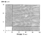
Pbの過剰量と昇温速度とは結晶構造に影響する。パイロクロア相の核生成が抑制するためには、上記のようにPb量を0%より多くまたは昇温速度10℃/秒以上とすることが有効であり、望ましくはPb量を0%より多くかつ昇温速度10℃/秒以上、さらに望ましくは、図4の範囲Aに示すようにPb量を5%以上かつ昇温速度20℃/秒以上とすることが有効である。
【0039】
酸素雰囲気としては、少なくとも一定時間乾燥した酸素雰囲気を用いることが得られる薄膜の品質の点より望ましいが、必要に応じて加湿することも可能である。
【0040】
バッファ層12は、上記の固相エピタキシャル成長を単数回または複数回行うことにより形成するが、1回の固相エピタキシャル成長で形成されるPLZT薄膜の膜厚を、10〜1000nmとすることが好ましく、50〜200nmとすることがより好ましい。
【0041】
なお、固相エピタキシャル成長の後は、結晶成長温度未満の温度、望ましくは100〜600℃の温度範囲で保持し、その後冷却することが望ましい。冷却は、0.01〜100℃/秒の冷却速度で行なうことが好ましい。
【0042】
以上の方法によって、材質の異なる単結晶基板10上に、密度および屈折率が単結晶並みであり、表面が光学的に平滑である、例えば、Pb(Zr1-xTix)O3(PZT),Pb1-xLax(Zr1-yTiy)1-x/4O3(PLZT)などの単結晶状のPLZT系バッファ層12を、形成することができる。
【0043】
次に、バッファ層12上に、単結晶状またはエピタキシャル状でありABO3型ペロブスカイト相構造を有する導電性または半導電性の薄膜14(以下、「導電性または半導電性の薄膜14」という)を形成する。
【0044】
導電性または半導電性の薄膜14の材料としては、SrRuO3、NbドープSrTiO3、LaドープSrTiO3、BaPbO3、YBa2Cu3O7-x、SrVO3、LaNiO3、La0.5Sr0.5CoO3などを用いることが可能であり、SrRuO3を用いることが品質の点より最も望ましいが、これらに限定されるわけではなく、PLZTバッファ層に類似の結晶対称性と格子定数を有する材料より選択することができる。
【0045】
導電性または半導電性の薄膜14は、電子ビーム蒸着、フラッシュ蒸着、イオンプレーティング、Rf−マグネトロンスパッタリング、イオンビームスパッタリング、レーザーアブレーション、MBE、CVD、プラズマCVD、MOCVDなどの気相エピタキシャル成長法、およびゾルゲル法、MOD法などのウエット・プロセスによる固相エピタキシャル成長法より選ばれるエピタキシャル成長方法によって、バッファ層上に作製することが可能である。
【0046】
以上の方法によって、材質の異なる単結晶基板10上に、単結晶並みの結晶性を有し、表面が光学的に平滑である、例えば、SrRuO3などの単結晶状の導電性または半導電性の薄膜14を形成することができる。
【0047】
【実施例】
(実施例1)
サファイアAl2O3(1102)単結晶基板上へ、固相エピタキシによって膜厚10nmのエピタキシャルPLZT(28/0/100)バッファ層を成長させ、さらに膜厚90nmのエピタキシャルPLZT(9/65/35)バッファ層を成長させ、さらに膜厚100nmのエピタキシャルSrRuO3を成長させることにより、図2に示す構造の薄膜構造体を単結晶基板上に形成した。
【0048】
まず、無水酢酸鉛(Pb(CH3COO)2)、ランタンイソプロポキシド(La(O−i−C3H7)3)、およびチタンイソプロポキシド(Ti(O−i−C3H7)4)を出発原料として、Pbが他の元素に対して化学量論組成となるように、Pb:La:Ti=72:28:100の割合で2−メトキシエタノールに溶解し、6時間の蒸留を行ったのち18時間の還流を行い、最終的にTi濃度で0.6MのPLZT(28/0/100)用前駆体溶液を得た。
【0049】
この前駆体溶液を0.2μmのフィルターを通して、Al2O3基板へスピンコーティングを行った。以上の操作はすべてN2雰囲気中にて行った。スピンコーティングの前に、基板は溶剤洗浄、HClによるエッチング、脱イオン水によるリンスを行い、最後にN2中にてエタノールのスピンコーティングによって乾燥した。
【0050】
次に、加湿O2雰囲気中で10℃/secにて300℃まで昇温して、300℃にて2分間保持の後、10℃/secにて650℃まで昇温して、650℃にて30分間保持し、最後に電気炉の電源を切り冷却した。これにより膜厚10nmのPLZT(28/0/100)バッファ層を固相エピタキシャル成長した。PLZT(28/0/100)バッファ層の表面を原子間力顕微鏡(AFM)によって観察すると、図5に示すような島状構造の形態になっていた。
【0051】
次に、同様に無水酢酸鉛、ランタンイソプロポキシド、ジルコニウムイソプロポキシド(Zr(O−i−C3H7)4)、およびチタンイソプロポキシドを出発原料として、Pbが他の元素に対して化学量論組成となるように、Pb:La:Zr:Ti=91:9:65:35の割合で2−メトキシエタノールに溶解し、6時間の蒸留を行ったのち18時間の還流を行い、最終的にZr+Ti濃度で0.6MのPLZT(9/65/35)用前駆体溶液を得た。この前駆体溶液を0.2μmのフィルターを通して、PLZT(28/0/100)バッファ層を設けたAl2O3基板へスピンコーティングを行った。以上の操作はすべてN2雰囲気中にて行った。
【0052】
次に、加湿O2雰囲気中で10℃/secにて300℃まで昇温して、300℃にて2分間保持の後、10℃/secにて650℃まで昇温して、650℃にて30分間保持し、最後に電気炉の電源を切り冷却した。これにより膜厚90nmのPLZT(9/65/35)薄膜を固相エピタキシャル成長した。
【0053】
この後、Rfマグネトロン・スパッタリングによって基板温度600℃、基板/ターゲット間距離50mm、Rfパワー50W、Ar/O2雰囲気、圧力1Paにて、膜厚100nmのSrRuO3導電性薄膜のエピタキシャル成長を行った。
【0054】
図6に示すように、X線回折θ−2θパターンによると、SrRuO3(110)の回折強度は強く、SrRuO3導電性薄膜はペロブスカイト単一相で、各層の結晶学的関係が、単一配向のSrRuO3(110)//PLZT(110)//PLZT(110)//Al2O3(1102)の構造が得られていた。SrRuO3(110)面によるロッキングカーブ半値幅は2.0°と良好であった。
【0055】
また、SrRuO3導電性薄膜の表面を、光学顕微鏡により観察したが、表面が均一なために何も見えず、AFMによって観察した結果も、図7に示すように、表面は極めて均一かつ平滑であり、粒界や細孔の全くみられない、コントラストの得られないほど鏡面状の表面であり、粗さもRaでわずかに1.3nmであった。また、抵抗率も0.2mΩ・cm程度と良好であった。
(比較例1)
サファイアAl2O3(1102)単結晶基板上へ、RfマグネトロンスパッタリングによってSrRuO3導電性薄膜を直接成長させた。成長条件は基板温度600℃、基板/ターゲット間距離50mm、Rfパワー50W、Ar/O2雰囲気、圧力1Paとした。図8に示すように、X線回折θ−2θパターンによると、同定不能の弱いピークがわずかに見られたのみであり、エピタキシャルなSrRuO3薄膜を得ることができなかった。
(参考例2)
実施例1とほぼ同様にして、サファイアAl2O3(1102)単結晶基板上へ固相エピタキシによって膜厚100nmのエピタキシャルPZT(30/70) バッファ層を成長させ、さらにSrRuO3導電性薄膜を成長させることにより、図1に示す構造の薄膜構造体を単結晶基板上に形成した。
【0056】
SrRuO3導電性薄膜の表面は極めて均一かつ平滑であり、X線回折θ−2θパターンによると、SrRuO3導電性薄膜はペロブスカイト単一相で、各層の結晶学的関係が、単一配向のSrRuO3(110)//PZT(110)//Al2O3(1102)の構造が得られた。
(実施例3)
実施例1とほぼ同様にして、サファイアAl2O3(1102)単結晶基板上へ固相エピタキシによって膜厚10nmのエピタキシャルPLZT(20/0/100)バッファ層を成長させ、エピタキシャルPZT(52/48)バッファ層を成長させ、さらにSrRuO3導電性薄膜を成長させることにより、図2に示す構造の薄膜構造体を単結晶基板上に形成した。
【0057】
SrRuO3導電性薄膜の表面は極めて均一かつ平滑であり、X線回折θ−2θパターンによると、SrRuO3導電性薄膜はペロブスカイト単一相で、各層の結晶学的関係が、単一配向のSrRuO3(110)//PZT(110)//PLZT(110)//Al2O3(1102)の構造が得られた。
(実施例4)
実施例1とほぼ同様にして、サファイアAl2O3(1102)単結晶基板上へ固相エピタキシによって膜厚10nmのエピタキシャルPZT(20/80)バッファ層を成長させ、エピタキシャルPZT(25/75)バッファ層を成長させた。さらにSrRuO3導電性薄膜の金属有機化合物前駆体前駆体溶液を、PLZT(25/75)バッファ層を設けたAl2O3基板へスピンコーティングを行い、O2雰囲気中で10℃/secにて300℃まで昇温して、300℃にて2分間保持の後、10℃/secにて650℃まで昇温して、650℃にて30分間保持し、最後に電気炉の電源を切り冷却した。これにより膜厚100nmのSrRuO3導電性薄膜を固相エピタキシャル成長させた。
【0058】
SrRuO3導電性薄膜の表面は極めて均一かつ平滑であり、X線回折θ−2θパターンによると、SrRuO3導電性薄膜はペロブスカイト単一相で、各層の結晶学的関係が、単一配向のSrRuO3(110)//PZT(110)//PZT(110)//Al2O3(1102)の構造が得られた。
(実施例5)
実施例1とほぼ同様にして、サファイアAl2O3(0001)単結晶基板上へ固相エピタキシによって膜厚5nmのエピタキシャルPLZT(28/0/100)バッファ層を成長させ、エピタキシャルPLZT(8/65/35)バッファ層を成長させ、さらにSrRuO3導電性薄膜を成長させることにより、図2に示す構造の薄膜構造体を単結晶基板上に形成した。
【0059】
SrRuO3導電性薄膜の表面は極めて均一かつ平滑であり、X線回折θ−2θパターンによると、SrRuO3導電性薄膜はペロブスカイト単一相で、各層の結晶学的関係が、単一配向のSrRuO3(111)//PLZT(111)//PLZT(111)//Al2O3(0001)の構造が得られた。
(実施例6)
サファイアAl2O3(0001)単結晶基板上へ、Rfマグネトロンスパッタリングによって基板温度650℃にて膜厚10nmのエピタキシャルPLZT(28/0/100)バッファ層を成長させ、同じくRfマグネトロンスパッタリングによって基板温度650℃にてエピタキシャルPLZT(8/65/35)バッファ層を成長させ、さらにRfマグネトロンスパッタリングによって基板温度600℃にてSrRuO3導電性薄膜を成長させることにより、図2に示す構造の薄膜構造体を単結晶基板上に形成した。
【0060】
SrRuO3導電性薄膜の表面は極めて均一かつ平滑であり、X線回折θ−2θパターンによると、SrRuO3導電性薄膜はペロブスカイト単一相で、各層の結晶学的関係が、単一配向のSrRuO3(111)//PLZT(111)//PLZT(111)//Al2O3(0001)の構造が得られた。
(実施例7)
MgO(100)単結晶基板上へ、実施例1と同様に固相エピタキシャル成長によって膜厚10nmのエピタキシャルPLZT(28/0/100)バッファ層を成長させ、エピタキシャルPLZT(8/65/35)バッファ層を成長させ、さらにSrRuO3導電性薄膜を成長させることにより、図2に示す構造の薄膜構造体を単結晶基板上に形成した。
【0061】
SrRuO3導電性薄膜の表面は極めて均一かつ平滑であり、X線回折θ−2θパターンによると、SrRuO3導電性薄膜はペロブスカイト単一相で、各層の結晶学的関係が、単一配向のSrRuO3(100)//PLZT(001)//PLZT(001)//MgO(100)の構造が得られた。
(実施例8)
MgOバッファ層をエピタキシャル成長したGaAs(100)単結晶基板上へ、膜厚10nmのエピタキシャルPLZT(28/0/100)バッファ層とエピタキシャルPLZT(8/65/35)バッファ層を成長させ、さらにSrRuO3導電性薄膜を成長させることにより、図2に示す構造の薄膜構造体を単結晶基板上に形成した。
【0062】
GaAs(100)基板へのエピタキシャルMgOバッファ層は、金属Mgターゲット表面をUVレーザーパルスにより瞬間的に加熱し蒸着を行うエキシマレーザーデポジション法を用い、O2雰囲気での反応性成膜によって350℃の基板温度で成長した。さらに、MgOバッファー層上へPLZTバッファ層をレーザーデポジション法によってエピタキシャル成長した後、エピタキシャルPLZT(8/65/35)バッファ層を成長させ、さらにSrRuO3導電性薄膜を成長させた。
【0063】
SrRuO3導電性薄膜の表面は極めて均一かつ平滑であり、X線回折θ−2θパターンによると、SrRuO3導電性薄膜はペロブスカイト単一相で、各層の結晶学的関係が、単一配向のSrRuO3(10)//PLZT(001)//PLZT(001)//MgO(100)//GaAs(100)の構造が得られた。
【0064】
【発明の効果】
本発明によれば、単結晶状またはエピタキシャル状でありABO3型ペロブスカイト相構造を有する導電性または半導電性の薄膜を表面に有する薄膜構造体を単結晶基板の表面に容易に形成することができる。
【0065】
この薄膜構造体の表面は、平滑であり、かつ高い結晶性を有する単結晶状またはエピタキシャル状でありABO3型ペロブスカイト相構造を有する導電性または半導電性の薄膜からなるため、光スイッチ、光変調素子、光偏向素子、第二高調波素子などのエピタキシャル薄膜光導波路や、不揮発性メモリ、FETなどのエピタキシャル薄膜を設ける導電性基板として利用することができる。
【図面の簡単な説明】
【図1】本発明の薄膜構造体の構造の一例を模式的に表す断面図である。
【図2】本発明の薄膜構造体の構造の他の一例を模式的に表す断面図である。
【図3】Pb1-xLax(Zr1-yTiy)1-x/4O3(PLZT)の相図である。
【図4】過剰Pb量と昇温速度の好適範囲を示すグラフである。
【図5】実施例1のバッファ層表面の原子間力顕微鏡(AFM)写真である。
【図6】実施例1のSrRuO3導電性薄膜のX線回折パターンである。
【図7】実施例1のバッファ層表面の原子間力顕微鏡(AFM)写真である。
【図8】比較例1のSrRuO3導電性薄膜のX線回折パターンである。
【図9】単結晶基板上に設けられた0<x<0.30、0<y<0.20の範囲のPLZT薄膜の模式的断面図である。
【図10】膜厚が1〜40nmで単結晶基板上に設けられた、0<x<0.30、0<y<0.20の範囲のPLZTバッファ層の模式的断面図である。
【符号の説明】
10 単結晶基板
12 バッファ層
12A 第1バッファ層
12B 第2バッファ層
14 導電性または半導電性の薄膜[0001]
BACKGROUND OF THE INVENTION
The present invention relates to a thin film structure formed on the surface of a single crystal substrate and a method for manufacturing the same. The present invention relates to a thin film structure that can be used as a conductive substrate for providing an epitaxial thin film such as a conductive memory and FET, and a method for manufacturing the same.
[0002]
[Prior art]
Pb 1-x La x (Zr y Ti 1-y ) 1-x / 4 O Three The (PLZT) -based material has an extremely large electro-optic coefficient among oxide ferroelectric materials having a good electro-optic effect, and LiNbO has a composition exhibiting a primary electro-optic coefficient. Three GH Haertling and CE Land, J. Amer. Ceram. Soc.Vol. Is a composition that exhibits a second order electro-optic coefficient and has the highest level among ferroelectric materials. 54. p.1 (1971), etc., and its application to optical devices is expected.
[0003]
The inventors have made SrTiO doped with impurities. Three A PLZT thin film having a uniform perovskite phase can be epitaxially grown on the substrate, and the PLZT thin film formed on this substrate has been found to exhibit excellent characteristics and has already been filed (Japanese Patent Application No. 10- 157609).
[0004]
However, SrTiO doped with impurities Three However, only a substrate having a size of about 1 inch can be manufactured, and the application range is limited because the substrate size is limited. Also, SrTiO doped with impurities Three Since there is no cleavage, even if a PLZT thin film is provided, the end face must be mechanically polished in order to use it as an optical waveguide device, and the process is complicated and requires a lot of production time. .
[0005]
[Problems to be solved by the invention]
In order to broaden the application range of the PLZT material and to manufacture an optical waveguide device using the PLZT material by a simpler method, the present inventors Three We are investigating the formation of a conductive thin film having a perovskite phase structure and capable of epitaxially growing a PLZT thin film on a general-purpose substrate such as a sapphire substrate or an MgO substrate.
[0006]
If a conductive thin film having a uniform perovskite phase can be epitaxially grown on a substrate such as sapphire on which a substrate having a size of several inches can be grown, a wide range of applications can be opened. Further, if a PLZT thin film can be epitaxially grown through a conductive thin film on a sapphire substrate, an MgO substrate, or a GaAs substrate or Si substrate using MgO as a buffer layer through a conductive thin film, the end face is easily formed by cleavage. It is possible to achieve a significant cost reduction. If a PLZT thin film can be epitaxially grown via a conductive thin film on a sapphire substrate, MgO substrate, or a GaAs substrate or Si substrate using MgO as a buffer layer, monolithic integration with a semiconductor device is possible.
[0007]
However, sapphire and MgO substrates are ABO Three It was very difficult to epitaxially grow a conductive thin film having a uniform perovskite phase structure on these single crystal substrates without having a perovskite phase structure of the type. .
[0008]
Accordingly, an object of the present invention is a thin film structure formed on the surface of a single crystal substrate, which is single crystal or epitaxial and has an ABO Three A thin film structure having a conductive or semiconductive thin film having a perovskite phase structure on its surface and a method for manufacturing the same.
[0009]
[Means for Solving the Problems]
To achieve the above objective, According to reference examples The thin film structure is a thin film structure formed on the surface of a single crystal substrate, and is a single crystal or epitaxial Pb provided on the surface of the single crystal substrate. 1-x La x (Zr y Ti 1-y ) 1-x / 4 O Three And a single crystal or epitaxial layer provided on the surface of the buffer layer. Three And a conductive or semiconductive thin film having a perovskite phase structure.
[0010]
Also, According to reference examples The method of manufacturing a thin film structure is a method of manufacturing a thin film structure formed on the surface of a single crystal substrate, and a single crystal or epitaxial Pb is formed on the surface of the single crystal substrate. 1-x La x (Zr y Ti 1-y ) 1-x / 4 O Three After the buffer layer is formed, the surface of the buffer layer is monocrystalline or epitaxial and is ABO. Three A conductive or semiconductive thin film having a perovskite phase structure is formed.
[0011]
Nb-doped SrTiO Three La-doped SrTiO Three , BaPbO Three , SrRuO Three , YBa 2 Cu Three O 7-x , SrVO Three LaNiO Three , La 0.5 Sr 0.5 CoO Three Conductive or semiconductive materials such as non-perovskite surfaces have ABO Three An epitaxial thin film having a type perovskite phase structure is difficult to grow, and the thin film after growth has poor crystallinity, and a non-perovskite phase is likely to be mixed therein.
[0012]
Invention according to reference example Then, single crystalline or epitaxial Pb 1-x La x (Zr y Ti 1-y ) 1-x / 4 O Three The buffer layer is made of a perovskite phase structure, and a conductive or semiconductive epitaxial thin film is formed through this buffer layer, so that ABO is formed on the single crystal substrate. Three A conductive or semiconductive epitaxial thin film having a perovskite phase structure can be provided.
[0013]
Single crystal or epitaxial and ABO Three As a conductive or semiconductive thin film having a perovskite phase structure, SrRuO Three A thin film made of is particularly preferred.
[0014]
For the formation of the buffer layer, solid phase epitaxial growth using application of a metal organic compound solution is the most desirable growth method because of good flattening characteristics.
[0015]
And The thin film structure according to claim 1, Invention according to reference example In the above, the buffer layer is made of single crystal or epitaxial Pb in the range of 0 <x <0.30 and 0 <y <0.20. 1-x La x (Zr y Ti 1-y ) 1-x / 4 O Three And a single crystal or epitaxial Pb in the range of 0 <x <0.20 and 0.20 <y <1.0 provided on the surface of the first buffer layer. 1-x La x (Zr y Ti 1-y ) 1-x / 4 O Three And a second buffer layer.
[0016]
Claims 7 Is a method for manufacturing a thin film structure formed on the surface of a single crystal substrate, and 0 <x <0.30, 0 <y <on the surface of the single crystal substrate. Single crystal or epitaxial Pb in the range of 0.20 1-x La x (Zr y Ti 1-y ) 1-x / 4 O Three A first buffer layer is formed, and a single crystal or epitaxial Pb in the range of 0 <x <0.20 and 0.20 <y <1.0 is formed on the surface of the first buffer layer. 1-x La x (Zr y Ti 1-y ) 1-x / 4 O Three A second buffer layer is formed, and the surface of the second buffer layer is monocrystalline or epitaxial and is ABO. Three A conductive or semiconductive thin film having a perovskite phase structure is formed.
[0017]
PLZT having a composition in the range of 0 <x <0.30 and 0 <y <0.20 constituting the first buffer layer is difficult to form a pyrochlore layer and can easily perform epitaxial growth of a perovskite single phase. Next, when a second buffer layer made of PLZT having a composition in the range of 0 <x <0.20 and 0.20 <y <1.0 is epitaxially grown on the surface of the first buffer layer, the second buffer layer Since it grows on the surface of the first buffer layer having the same crystal structure and composition, it is usually difficult to grow a perovskite single phase. However, as a perovskite single phase without the formation of a pyrochlore layer, Can be epitaxially grown. Since the obtained second buffer layer has a perovskite phase structure, ABO is passed through this second buffer layer. Three A conductive or semiconductive epitaxial thin film having a perovskite phase structure can be provided.
[0018]
In addition, PLZT having a composition in the range of 0 <x <0.30 and 0 <y <0.20 constituting the first buffer layer can easily form deep grooves in the crystal grain boundaries as shown in FIG. The thickness of the first buffer layer is preferably in the range of 1 to 40 nm, and the crystal grains are preferably separated into islands as shown in FIG.
[0019]
Since the crystal grains of the first buffer layer are in the form of islands, when the second buffer layer is epitaxially grown on the surface of the first buffer layer, it becomes possible to fill the gap without creating a gap between the islands. The surface of the second buffer layer becomes smooth. Further, since the obtained second buffer layer has a perovskite phase structure and good crystallinity and smoothness, a conductive or semiconductive epitaxial thin film is formed through this second buffer layer. And better quality ABO Three A conductive or semiconductive epitaxial thin film having a perovskite phase structure can be formed.
[0020]
In the present invention, the term “single crystal” is generally called “epitaxial”, from a defect-free one obtained by thinning a single crystal as it is to one containing crystal defects such as twins. , But the crystal orientation is unidirectionally oriented in one direction at least by the θ-2θ X-ray diffraction pattern, that is, the random orientation plane is identified as 1% or less of the diffraction intensity of the single orientation plane .
[0021]
DETAILED DESCRIPTION OF THE INVENTION
Reference example As shown in FIG. 1, the thin film structure is formed of single crystal or epitaxial Pb provided on the surface of the single crystal substrate 10. 1-x La x (Zr y Ti 1-y ) 1-x / 4 O Three A buffer layer 12 comprising a single crystal or an epitaxial layer provided on the surface of the buffer layer 12 and ABO. Three And a conductive or semiconductive thin film 14 having a type perovskite phase structure. Hereinafter, according to the manufacturing process, Along with reference examples, the present invention The thin film structure will be described in detail.
[0022]
As a material of the single crystal substrate 10, ZrO 2 , Y 2 O Three 8% -ZrO 2 , MgO, MgAl 2 O Four , Al 2 O Three , ZnO, ZnGa 2 O Four , CdGa 2 O Four , CdGa 2 O Four , Mg 2 TiO Four MgTi 2 O Four , SrTiO Three , BaTiO Three , BaZrO Three LaAlO Three , LiNbO Three LiTaO Three And oxides such as Si, Ge, diamond and the like, AlAs, AlSb, AlP, GaAs, GaSb, InP, InAs, InSb, AlGaP, AlLnP, AlGaAs, AlInAs, AlAsSb II-VI compound semiconductors such as ZnS, ZnSe, ZnTe, CaSe, CdTe, HgSe, HgTe, CdS, and the like. Among these, Al is available for large substrates 2 O Three Si, MgO, MgO provided on the surface, and GaAs provided MgO on the surface are more preferable.
[0023]
First, the buffer layer 12 is provided on the surface of the single crystal substrate 10.
[0024]
The buffer layer 12 is made of single crystal or epitaxial Pb. 1-x La x (Zr y Ti 1-y ) 1-x / 4 O Three It is. When the buffer layer has a single layer structure, an epitaxial Pb in the range of 0 <x <0.3 and 0.1 <y <0.6 can be formed because a highly smooth surface can be formed. 1-x La x (Zr y Ti 1-y ) 1-x / 4 O Three It is preferable to use (PLZT).
[0025]
And the thin film structure of the present invention, As shown in FIG. 2, the buffer layer has a two-layer configuration of a first buffer layer 12A and a second buffer layer 12B. Is .
[0026]
When the buffer layer has a two-layer structure, the first buffer layer 12A includes an epitaxial Pb in the range of 0 <x <0.30 and 0 <y <0.20 indicated by the region A in FIG. 1-x La x (Zr y Ti 1-y ) 1-x / 4 O Three (PLZT) is used, and the second buffer layer 12B has an epitaxial Pb in the range of 0 <x <0.20 and 0.20 <y <1.0 shown by the region B in FIG. 1-x La x (Zr y Ti 1-y ) 1-x / 4 O Three (PLZT) is used. In addition, from the viewpoint of surface smoothing, the thickness of the first buffer layer 12A is preferably in the range of 1 to 40 nm.
[0027]
The buffer layer 12 is formed by vapor phase epitaxial growth methods such as electron beam evaporation, flash evaporation, ion plating, Rf-magnetron sputtering, ion beam sputtering, laser ablation, MBE, CVD, plasma CVD, MOCVD, and sol-gel. It can be formed on the single crystal substrate 10 by an epitaxial growth method selected from a solid phase epitaxial growth method using a wet process such as a MOD method or a MOD method. A coating process in which the obtained ferroelectric precursor solution is applied to form a thin film, a thermal decomposition process in which the thin film is pyrolyzed, and a crystal in which the pyrolyzed thin film is heated to a crystal growth temperature and solid phase epitaxially grown. A solid phase process in which the growth process is performed one or more times. Takisharu growth method is particularly preferred. A buffer layer having a flat surface can be formed by solid phase epitaxial growth using a metal organic compound solution.
[0028]
As the metal organic compound, metal alkoxides and metal salts which are reaction products of Pb, La, Zr and Ti metals and organic compounds, preferably organic compounds having a boiling point of 80 ° C. or higher at normal pressure are used. It is done.
[0029]
As an organic ligand of a metal alkoxide compound, R 1 O- or R 2 OR Three O- (wherein R 1 And R 2 Represents an aliphatic hydrocarbon group, R Three Represents a divalent aliphatic hydrocarbon group which may have an ether bond). These metal alkoxide compounds are R 1 OH or R 2 OR Three It can be synthesized by distillation or reflux in an organic solvent represented by OH, and R 1 And R 2 As the aliphatic hydrocarbon group, an alkyl group having 1 to 4 carbon atoms is preferable, and R Three Are preferably an alkylene group having 2 to 4 carbon atoms and a divalent group having 4 to 8 carbon atoms in which an alkylene group having 2 to 4 carbon atoms is bonded by an ether bond.
[0030]
Specifically, as the solvent having a boiling point of 80 ° C. or more, for example, (CH Three ) 2 CHOH (boiling point 82.3 ° C.), CH Three (C 2 H Five ) CHOH (boiling point 99.5 ° C.), (CH Three ) 2 CHCH 2 OH (boiling point 108 ° C.), C Four H 9 OH (boiling point 117.7 ° C.), (CH Three ) 2 CHC 2 H Four OH (boiling point 130.5 ° C.), CH Three OCH 2 CH 2 OH (boiling point 124.5 ° C.), C 2 H Five OCH 2 CH 2 OH (boiling point 135 ° C.), C Four H 9 OCH 2 CH 2 Alcohols such as OH (boiling point 171 ° C.) are most desirable, but are not limited to these. 2 H Five OH (boiling point: 78.3 ° C.) can also be used.
[0031]
The ferroelectric precursor solution comprises a plurality of metal organic compounds selected from metal alkoxides and metal salts, alcohols, diketones having a predetermined composition, preferably a boiling point of 80 ° C. or higher at normal pressure, It can be obtained by mixing in a solvent selected from ketone acids, alkyl esters, oxyacids, oxyketones, and acetic acid, or by reacting with these solvents.
[0032]
The composition of the metal organic compound is Pb 1-x La x (Zr y Ti 1-y ) 1-x / 4 O Three It is preferable that Pb is contained in excess of the ratio of Pb, La, Zr, Ti corresponding to the stoichiometric composition of Pb, and it is preferable to make Pb 5 at% (5 mol%) or more. It is also effective to add a small amount of various metal organic compounds containing metal elements other than Pb, La, Zr, and Ti as necessary.
[0033]
The ferroelectric precursor solution can be applied to the surface of a single crystal substrate after hydrolysis of the added metal organic compound, but in order to obtain a high-quality epitaxial ferroelectric thin film, the ferroelectric precursor solution can be applied. It is preferable not to decompose. From the viewpoint of the quality of the thin film obtained, the ferroelectric precursor solution is preferably adjusted in a dry nitrogen or argon atmosphere.
[0034]
The ferroelectric precursor solution is applied by a method selected from a spin coating method, a dipping method, a spray method, a screen printing method, and an ink jet method. These coating steps are preferably performed in a dry nitrogen or argon atmosphere from the viewpoint of the quality of the thin film obtained.
[0035]
An amorphous thin film is formed by thermally decomposing a thin film obtained by applying the ferroelectric precursor solution at a temperature at which crystallization does not occur. The temperature range of thermal decomposition is preferably 100 to 500 ° C, more preferably 200 to 400 ° C. Moreover, it is preferable to heat up to the thermal decomposition temperature at a temperature increase rate of 0.1 to 1000 ° C./second, preferably at a temperature increase rate of 1 to 100 ° C./second. The thermal decomposition and the temperature increase are preferably performed in an oxygen-containing atmosphere, preferably in oxygen.
[0036]
The pyrolyzed thin film is heated at the crystal growth temperature for 1 second to 24 hours, preferably 10 seconds to 12 hours, and the ferroelectric thin film is grown on the substrate surface by solid phase epitaxial growth. The temperature range for crystal growth is preferably 600 ° C. or more, more preferably 600 to 1200 ° C., and particularly preferably 600 to 800 ° C. Moreover, it is preferable to raise the temperature rapidly at a temperature rising rate of 10 to 500 ° C./second, preferably a temperature rising rate of 20 to 100 ° C./second until the crystal growth temperature. The crystal growth and the temperature increase are preferably performed in an oxygen-containing atmosphere, preferably in oxygen.
[0037]
In the crystal growth step, when the temperature is raised to the crystal growth temperature, the temperature range in which nuclei of the pyrochlore phase are generated, specifically, the temperature range of 350 to 450 ° C. is set to a temperature increase rate of 10 to 500 ° C./second, More preferably, it is preferable to increase the temperature at a high rate of 20 to 100 ° C./second. Thus, the nucleation of a pyrochlore phase is suppressed by heating up at high speed. From the viewpoint of productivity, it is preferable to apply the temperature increase rate not only in the nucleation temperature range of the pyrochlore phase but also throughout the temperature increase process.
[0038]
The excess amount of Pb and the heating rate affect the crystal structure. In order to suppress nucleation of the pyrochlore phase, it is effective to set the Pb amount to be greater than 0% or a temperature increase rate of 10 ° C./second or more as described above, and desirably the Pb amount is greater than 0% and It is effective that the temperature rising rate is 10 ° C./second or more, and more desirably, the Pb content is 5% or more and the temperature rising rate is 20 ° C./second or more as shown in the range A of FIG.
[0039]
As the oxygen atmosphere, it is desirable from the viewpoint of the quality of the thin film obtained to use an oxygen atmosphere that has been dried for at least a certain period of time, but it may be humidified as necessary.
[0040]
The buffer layer 12 is formed by performing the above-mentioned solid phase epitaxial growth one or more times, but the film thickness of the PLZT thin film formed by one solid phase epitaxial growth is preferably 10 to 1000 nm. More preferably, it is set to ˜200 nm.
[0041]
In addition, after solid phase epitaxial growth, it is desirable to hold at a temperature lower than the crystal growth temperature, desirably 100 to 600 ° C., and then cool. Cooling is preferably performed at a cooling rate of 0.01 to 100 ° C./second.
[0042]
By the above method, on the single crystal substrate 10 of different materials, the density and refractive index are the same as those of the single crystal, and the surface is optically smooth. For example, Pb (Zr 1-x Ti x ) O Three (PZT), Pb 1-x La x (Zr 1-y Ti y ) 1-x / 4 O Three A monocrystalline PLZT buffer layer 12 such as (PLZT) can be formed.
[0043]
Next, on the buffer layer 12, it is single crystal or epitaxial and is ABO. Three A conductive or semiconductive thin film 14 having a type perovskite phase structure (hereinafter referred to as “conductive or semiconductive thin film 14”) is formed.
[0044]
Examples of the material of the conductive or semiconductive thin film 14 include SrRuO. Three Nb-doped SrTiO Three La-doped SrTiO Three , BaPbO Three , YBa 2 Cu Three O 7-x , SrVO Three LaNiO Three , La 0.5 Sr 0.5 CoO Three It is possible to use SrRuO Three However, the present invention is not limited to these, and can be selected from materials having similar crystal symmetry and lattice constant to the PLZT buffer layer.
[0045]
The conductive or semiconductive thin film 14 is formed by vapor phase epitaxial growth methods such as electron beam evaporation, flash evaporation, ion plating, Rf-magnetron sputtering, ion beam sputtering, laser ablation, MBE, CVD, plasma CVD, MOCVD, and the like. It can be formed on the buffer layer by an epitaxial growth method selected from a solid phase epitaxial growth method using a wet process such as a sol-gel method or a MOD method.
[0046]
By the above method, the single crystal substrate 10 made of different materials has the same crystallinity as the single crystal and the surface is optically smooth. For example, SrRuO Three A single crystal conductive or semiconductive thin film 14 such as can be formed.
[0047]
【Example】
Example 1
Sapphire Al 2 O Three (1102) A 10 nm-thick epitaxial PLZT (28/0/100) buffer layer is grown on a single crystal substrate by solid phase epitaxy, and a 90-nm thick epitaxial PLZT (9/65/35) buffer layer is further grown. Further, epitaxial SrRuO with a film thickness of 100 nm Three As a result, the thin film structure having the structure shown in FIG. 2 was formed on the single crystal substrate.
[0048]
First, anhydrous lead acetate (Pb (CH Three COO) 2 ), Lanthanum isopropoxide (La (O-i-C Three H 7 ) Three ), And titanium isopropoxide (Ti (O-i-C Three H7) Four ) As a starting material and dissolved in 2-methoxyethanol at a ratio of Pb: La: Ti = 72: 28: 100 so that Pb has a stoichiometric composition with respect to other elements, and distilled for 6 hours. Then, reflux was performed for 18 hours to finally obtain a precursor solution for PLZT (28/0/100) having a Ti concentration of 0.6M.
[0049]
This precursor solution was passed through a 0.2 μm filter and passed through Al. 2 O Three The substrate was spin coated. All the above operations are N 2 I went in the atmosphere. Prior to spin coating, the substrate is solvent cleaned, etched with HCl, rinsed with deionized water, and finally N 2 Dry in by spin coating with ethanol.
[0050]
Next, humidification O 2 The temperature was raised to 300 ° C. at 10 ° C./sec in the atmosphere, held at 300 ° C. for 2 minutes, then heated to 650 ° C. at 10 ° C./sec and held at 650 ° C. for 30 minutes, Finally, the electric furnace was turned off and cooled. As a result, a PLZT (28/0/100) buffer layer having a thickness of 10 nm was grown by solid phase epitaxial growth. When the surface of the PLZT (28/0/100) buffer layer was observed with an atomic force microscope (AFM), it was in the form of an island structure as shown in FIG.
[0051]
Next, similarly, anhydrous lead acetate, lanthanum isopropoxide, zirconium isopropoxide (Zr (Oi-C Three H 7 ) Four ), And titanium isopropoxide as a starting material, Pb: La: Zr: Ti = 91: 9: 65: 35 at a ratio of Pb: La: Zr: Ti = 91: 9: 65: 35 It was dissolved in ethanol, distilled for 6 hours, and then refluxed for 18 hours. Finally, a precursor solution for PLZT (9/65/35) having a Zr + Ti concentration of 0.6 M was obtained. This precursor solution was passed through a 0.2 μm filter, and an Al provided with a PLZT (28/0/100) buffer layer. 2 O Three The substrate was spin coated. All the above operations are N 2 I went in the atmosphere.
[0052]
Next, humidification O 2 The temperature was raised to 300 ° C. at 10 ° C./sec in the atmosphere, held at 300 ° C. for 2 minutes, then heated to 650 ° C. at 10 ° C./sec and held at 650 ° C. for 30 minutes, Finally, the electric furnace was turned off and cooled. Thereby, a 90 nm thick PLZT (9/65/35) thin film was grown by solid phase epitaxial growth.
[0053]
Thereafter, the substrate temperature is 600 ° C., the substrate / target distance is 50 mm, the Rf power is 50 W, Ar / O by Rf magnetron sputtering. 2 SrRuO with a film thickness of 100 nm in atmosphere and pressure of 1 Pa Three The conductive thin film was epitaxially grown.
[0054]
As shown in FIG. 6, according to the X-ray diffraction θ-2θ pattern, SrRuO Three The diffraction intensity of (110) is strong and SrRuO. Three The conductive thin film is a perovskite single phase, and the crystallographic relationship of each layer is a single orientation SrRuO. Three (110) // PLZT (110) // PLZT (110) // Al 2 O Three The structure of (1102) was obtained. SrRuO Three The rocking curve half width by the (110) plane was as good as 2.0 °.
[0055]
SrRuO Three Although the surface of the conductive thin film was observed with an optical microscope, nothing was seen because the surface was uniform, and the result of observation with AFM was that the surface was extremely uniform and smooth, as shown in FIG. In addition, the surface was so specular that no contrast was obtained, and the roughness was only 1.3 nm in terms of Ra. Further, the resistivity was as good as about 0.2 mΩ · cm.
(Comparative Example 1)
Sapphire Al 2 O Three (1102) SrRuO on a single crystal substrate by Rf magnetron sputtering Three A conductive thin film was directly grown. Growth conditions are: substrate temperature 600 ° C., substrate / target distance 50 mm, Rf power 50 W, Ar / O 2 The atmosphere and pressure were 1 Pa. As shown in FIG. 8, according to the X-ray diffraction θ-2θ pattern, only a few unidentifiable weak peaks were observed, and the epitaxial SrRuO Three A thin film could not be obtained.
( Reference example 2)
Almost the same as in Example 1, sapphire Al 2 O Three (1102) An epitaxial PZT (30/70) buffer layer having a thickness of 100 nm is grown on a single crystal substrate by solid phase epitaxy, and further SrRuO. Three A thin film structure having the structure shown in FIG. 1 was formed on a single crystal substrate by growing a conductive thin film.
[0056]
SrRuO Three The surface of the conductive thin film is extremely uniform and smooth, and according to the X-ray diffraction θ-2θ pattern, SrRuO Three The conductive thin film is a perovskite single phase, and the crystallographic relationship of each layer is a single orientation SrRuO. Three (110) // PZT (110) // Al 2 O Three The structure of (1102) was obtained.
(Example 3)
Almost the same as in Example 1, sapphire Al 2 O Three (1102) An epitaxial PLZT (20/0/100) buffer layer having a thickness of 10 nm is grown on a single crystal substrate by solid phase epitaxy, an epitaxial PZT (52/48) buffer layer is grown, and SrRuO is further grown. Three By growing the conductive thin film, a thin film structure having the structure shown in FIG. 2 was formed on the single crystal substrate.
[0057]
SrRuO Three The surface of the conductive thin film is extremely uniform and smooth, and according to the X-ray diffraction θ-2θ pattern, SrRuO Three The conductive thin film is a perovskite single phase, and the crystallographic relationship of each layer is a single orientation SrRuO. Three (110) // PZT (110) // PLZT (110) // Al 2 O Three The structure of (1102) was obtained.
Example 4
Almost the same as in Example 1, sapphire Al 2 O Three (1102) An epitaxial PZT (20/80) buffer layer having a thickness of 10 nm was grown on a single crystal substrate by solid phase epitaxy, and an epitaxial PZT (25/75) buffer layer was grown. Furthermore, SrRuO Three Conductive thin film metal organic compound precursor precursor solution is provided with Al with PLZT (25/75) buffer layer 2 O Three Perform spin coating on the substrate, O 2 The temperature was raised to 300 ° C. at 10 ° C./sec in the atmosphere, held at 300 ° C. for 2 minutes, then heated to 650 ° C. at 10 ° C./sec and held at 650 ° C. for 30 minutes, Finally, the electric furnace was turned off and cooled. As a result, SrRuO having a film thickness of 100 nm Three Conductive thin films were grown by solid phase epitaxial growth.
[0058]
SrRuO Three The surface of the conductive thin film is extremely uniform and smooth, and according to the X-ray diffraction θ-2θ pattern, SrRuO Three The conductive thin film is a perovskite single phase, and the crystallographic relationship of each layer is a single orientation SrRuO. Three (110) // PZT (110) // PZT (110) // Al 2 O Three The structure of (1102) was obtained.
(Example 5)
Almost the same as in Example 1, sapphire Al 2 O Three An epitaxial PLZT (28/0/100) buffer layer having a thickness of 5 nm is grown on a (0001) single crystal substrate by solid phase epitaxy, an epitaxial PLZT (8/65/35) buffer layer is grown, and SrRuO is further grown. Three By growing the conductive thin film, a thin film structure having the structure shown in FIG. 2 was formed on the single crystal substrate.
[0059]
SrRuO Three The surface of the conductive thin film is extremely uniform and smooth, and according to the X-ray diffraction θ-2θ pattern, SrRuO Three The conductive thin film is a perovskite single phase, and the crystallographic relationship of each layer is a single orientation SrRuO. Three (111) // PLZT (111) // PLZT (111) // Al 2 O Three A structure of (0001) was obtained.
(Example 6)
Sapphire Al 2 O Three An epitaxial PLZT (28/0/100) buffer layer having a thickness of 10 nm is grown on a (0001) single crystal substrate by Rf magnetron sputtering at a substrate temperature of 650 ° C., and epitaxially grown at a substrate temperature of 650 ° C. by Rf magnetron sputtering. A PLZT (8/65/35) buffer layer is grown, and SrRuO is further grown at a substrate temperature of 600 ° C. by Rf magnetron sputtering. Three By growing the conductive thin film, a thin film structure having the structure shown in FIG. 2 was formed on the single crystal substrate.
[0060]
SrRuO Three The surface of the conductive thin film is extremely uniform and smooth, and according to the X-ray diffraction θ-2θ pattern, SrRuO Three The conductive thin film is a perovskite single phase, and the crystallographic relationship of each layer is a single orientation SrRuO. Three (111) // PLZT (111) // PLZT (111) // Al 2 O Three A structure of (0001) was obtained.
(Example 7)
An epitaxial PLZT (28/0/100) buffer layer having a film thickness of 10 nm is grown on the MgO (100) single crystal substrate by solid phase epitaxial growth in the same manner as in Example 1, and the epitaxial PLZT (8/65/35) buffer layer is grown. And grow SrRuO Three By growing the conductive thin film, a thin film structure having the structure shown in FIG. 2 was formed on the single crystal substrate.
[0061]
SrRuO Three The surface of the conductive thin film is extremely uniform and smooth, and according to the X-ray diffraction θ-2θ pattern, SrRuO Three The conductive thin film is a perovskite single phase, and the crystallographic relationship of each layer is a single orientation SrRuO. Three A structure of (100) // PLZT (001) // PLZT (001) // MgO (100) was obtained.
(Example 8)
An epitaxial PLZT (28/0/100) buffer layer and an epitaxial PLZT (8/65/35) buffer layer having a thickness of 10 nm are grown on a GaAs (100) single crystal substrate on which an MgO buffer layer has been epitaxially grown, and further SrRuO. Three By growing the conductive thin film, a thin film structure having the structure shown in FIG. 2 was formed on the single crystal substrate.
[0062]
An epitaxial MgO buffer layer on a GaAs (100) substrate is formed by using an excimer laser deposition method in which a metal Mg target surface is instantaneously heated by a UV laser pulse to perform deposition. 2 The substrate was grown at a substrate temperature of 350 ° C. by reactive film formation in an atmosphere. Furthermore, after epitaxially growing a PLZT buffer layer on the MgO buffer layer by a laser deposition method, an epitaxial PLZT (8/65/35) buffer layer is grown, and SrRuO is further grown. Three A conductive thin film was grown.
[0063]
SrRuO Three The surface of the conductive thin film is extremely uniform and smooth, and according to the X-ray diffraction θ-2θ pattern, SrRuO Three The conductive thin film is a perovskite single phase, and the crystallographic relationship of each layer is a single orientation SrRuO. Three A structure of (10) // PLZT (001) // PLZT (001) // MgO (100) // GaAs (100) was obtained.
[0064]
【The invention's effect】
According to the present invention, it is single crystalline or epitaxial and is ABO. Three A thin film structure having a conductive or semiconductive thin film having a perovskite phase structure on the surface can be easily formed on the surface of the single crystal substrate.
[0065]
The surface of the thin film structure is smooth and has a single crystal or epitaxial shape with high crystallinity and is ABO. Three It consists of a conductive or semiconductive thin film having a perovskite phase structure, so that it can be used for epitaxial thin film optical waveguides such as optical switches, light modulation elements, light deflection elements, second harmonic elements, and non-volatile memories, FETs, etc. It can be used as a conductive substrate provided with a thin film.
[Brief description of the drawings]
FIG. 1 is a cross-sectional view schematically showing an example of the structure of a thin film structure of the present invention.
FIG. 2 is a cross-sectional view schematically showing another example of the structure of the thin film structure of the present invention.
FIG. 3 Pb 1-x La x (Zr 1-y Ti y ) 1-x / 4 O Three It is a phase diagram of (PLZT).
FIG. 4 is a graph showing a preferred range of excess Pb amount and temperature increase rate.
5 is an atomic force microscope (AFM) photograph of the buffer layer surface of Example 1. FIG.
FIG. 6 shows SrRuO of Example 1. Three It is an X-ray diffraction pattern of a conductive thin film.
7 is an atomic force microscope (AFM) photograph of the buffer layer surface of Example 1. FIG.
FIG. 8 shows SrRuO of Comparative Example 1 Three It is an X-ray diffraction pattern of a conductive thin film.
FIG. 9 is a schematic cross-sectional view of a PLZT thin film in a range of 0 <x <0.30 and 0 <y <0.20 provided on a single crystal substrate.
FIG. 10 is a schematic cross-sectional view of a PLZT buffer layer in a range of 0 <x <0.30 and 0 <y <0.20 provided on a single crystal substrate with a thickness of 1 to 40 nm.
[Explanation of symbols]
10 Single crystal substrate
12 Buffer layer
12A First buffer layer
12B Second buffer layer
14 Conductive or semiconductive thin film
Claims (13)
前記バッファ層が、0<x<0.30、0<y<0.20の範囲の単結晶状またはエピタキシャル状のPb 1-x La x (Zr y Ti 1-y ) 1-x/4 O 3 からなる第1バッファ層と、該第1バッファ層の表面に設けられた0<x<0.20、0.20<y<1.0の範囲の単結晶状またはエピタキシャル状のPb 1-x La x (Zr y Ti 1-y ) 1-x/4 O 3 からなる第2バッファ層と、によって構成される薄膜構造体。A thin film structure formed on the surface of the single crystal substrate, provided on the surface of the single crystal substrate a single crystal form or epitaxial-like Pb 1-x La x (Zr y Ti 1-y) 1-x A buffer layer made of / 4 O 3 , and a conductive or semi-conductive thin film having a single crystal or epitaxial ABO 3 type perovskite phase structure provided on the surface of the buffer layer ,
The buffer layer is, 0 <x <0.30,0 <y < ranging 0.20 single crystalline or epitaxial-like Pb 1-x La x (Zr y Ti 1-y) 1-x / 4 O A first buffer layer made of 3 and a single crystal or epitaxial Pb 1− in the range of 0 <x <0.20 and 0.20 <y <1.0 provided on the surface of the first buffer layer. x La x (Zr y Ti 1 -y) 1-x / 4 O 3 and a second buffer layer composed of a thin film structure constructed by.
Priority Applications (1)
| Application Number | Priority Date | Filing Date | Title |
|---|---|---|---|
| JP25588699A JP4399059B2 (en) | 1999-09-09 | 1999-09-09 | Thin film structure |
Applications Claiming Priority (1)
| Application Number | Priority Date | Filing Date | Title |
|---|---|---|---|
| JP25588699A JP4399059B2 (en) | 1999-09-09 | 1999-09-09 | Thin film structure |
Publications (2)
| Publication Number | Publication Date |
|---|---|
| JP2001080996A JP2001080996A (en) | 2001-03-27 |
| JP4399059B2 true JP4399059B2 (en) | 2010-01-13 |
Family
ID=17284946
Family Applications (1)
| Application Number | Title | Priority Date | Filing Date |
|---|---|---|---|
| JP25588699A Expired - Fee Related JP4399059B2 (en) | 1999-09-09 | 1999-09-09 | Thin film structure |
Country Status (1)
| Country | Link |
|---|---|
| JP (1) | JP4399059B2 (en) |
Families Citing this family (8)
| Publication number | Priority date | Publication date | Assignee | Title |
|---|---|---|---|---|
| JP5024310B2 (en) * | 2002-03-25 | 2012-09-12 | セイコーエプソン株式会社 | Inkjet recording head and inkjet printer |
| JP2005123361A (en) * | 2003-10-16 | 2005-05-12 | Sony Corp | Resistance change type nonvolatile memory and its manufacturing method, and method of forming resistance change layer |
| JP5376500B2 (en) * | 2008-12-04 | 2013-12-25 | 株式会社ノリタケカンパニーリミテド | Oxygen ion conductive ceramic membrane material and manufacturing method thereof |
| JP6083262B2 (en) * | 2012-03-14 | 2017-02-22 | Tdk株式会社 | Laminated thin film with heteroepitaxial PN junction oxide thin film |
| JP6923877B2 (en) | 2017-04-26 | 2021-08-25 | 国立大学法人埼玉大学 | Substrate manufacturing method |
| JP6943388B2 (en) | 2017-10-06 | 2021-09-29 | 国立大学法人埼玉大学 | Substrate manufacturing method |
| JP7121941B2 (en) | 2018-03-09 | 2022-08-19 | 国立大学法人埼玉大学 | Substrate manufacturing method |
| CN114086118B (en) * | 2021-11-09 | 2023-07-14 | 电子科技大学长三角研究院(湖州) | Self-supporting flexible film and preparation method thereof |
-
1999
- 1999-09-09 JP JP25588699A patent/JP4399059B2/en not_active Expired - Fee Related
Also Published As
| Publication number | Publication date |
|---|---|
| JP2001080996A (en) | 2001-03-27 |
Similar Documents
| Publication | Publication Date | Title |
|---|---|---|
| US5650362A (en) | Oriented conductive film and process for preparing the same | |
| JP3033067B2 (en) | Method for manufacturing multilayer ferroelectric conductive film | |
| EP0661754B1 (en) | Structure comprising a ferroelectric crystal thin film, its production method and a device using said structure | |
| JP3047316B2 (en) | Epitaxial ferroelectric thin film device and method for producing the same | |
| JP3310881B2 (en) | Laminated thin film, substrate for electronic device, electronic device, and method of manufacturing laminated thin film | |
| JPH06342920A (en) | Orientational ferroelectric thin-film element | |
| US20050162595A1 (en) | Optical deflection element and method of producing the same | |
| JPH10223476A (en) | Ferroelectric thin film and its manufacture | |
| JP4399059B2 (en) | Thin film structure | |
| US5852703A (en) | Ferroelectric thin film element and production method thereof | |
| JP2964780B2 (en) | Oriented multilayer ferroelectric thin film and method for producing the same | |
| JP2003086586A (en) | Orientational ferroelectric thin film element and method for manufacturing the same | |
| JP3235279B2 (en) | Manufacturing method of epitaxial ferroelectric thin film device | |
| JP4368004B2 (en) | Optical waveguide device and method for manufacturing optical waveguide device | |
| US20050082615A1 (en) | Epitaxial ferroelectric thin-film device and method of manufacturing the same | |
| JP2820009B2 (en) | Fabrication method of oriented ferroelectric thin film | |
| JP2889463B2 (en) | Oriented ferroelectric thin film device | |
| JPH11199393A (en) | Production of ferroelectric thin film element | |
| JP3199091B2 (en) | Stack of oriented thin films | |
| JP3513532B2 (en) | Optical switching element | |
| JP3186381B2 (en) | Method for producing oriented conductive thin film | |
| JPH06151602A (en) | Production of oriented ferroelectric thin film | |
| JP2001116943A (en) | Method for producing thin metal oxide film element | |
| JP3484990B2 (en) | Multilayer ferroelectric thin film | |
| JP3111220B1 (en) | Oriented single-layer ferroelectric oxide thin film, method for producing the same, and switching element using the ferroelectric thin film |
Legal Events
| Date | Code | Title | Description |
|---|---|---|---|
| A621 | Written request for application examination |
Free format text: JAPANESE INTERMEDIATE CODE: A621 Effective date: 20060821 |
|
| A711 | Notification of change in applicant |
Free format text: JAPANESE INTERMEDIATE CODE: A711 Effective date: 20070726 |
|
| A711 | Notification of change in applicant |
Free format text: JAPANESE INTERMEDIATE CODE: A711 Effective date: 20080527 |
|
| A131 | Notification of reasons for refusal |
Free format text: JAPANESE INTERMEDIATE CODE: A131 Effective date: 20090707 |
|
| A521 | Written amendment |
Free format text: JAPANESE INTERMEDIATE CODE: A523 Effective date: 20090907 |
|
| TRDD | Decision of grant or rejection written | ||
| A01 | Written decision to grant a patent or to grant a registration (utility model) |
Free format text: JAPANESE INTERMEDIATE CODE: A01 Effective date: 20091006 |
|
| A01 | Written decision to grant a patent or to grant a registration (utility model) |
Free format text: JAPANESE INTERMEDIATE CODE: A01 |
|
| A61 | First payment of annual fees (during grant procedure) |
Free format text: JAPANESE INTERMEDIATE CODE: A61 Effective date: 20091026 |
|
| FPAY | Renewal fee payment (event date is renewal date of database) |
Free format text: PAYMENT UNTIL: 20121030 Year of fee payment: 3 |
|
| R150 | Certificate of patent or registration of utility model |
Free format text: JAPANESE INTERMEDIATE CODE: R150 |
|
| FPAY | Renewal fee payment (event date is renewal date of database) |
Free format text: PAYMENT UNTIL: 20131030 Year of fee payment: 4 |
|
| R250 | Receipt of annual fees |
Free format text: JAPANESE INTERMEDIATE CODE: R250 |
|
| R250 | Receipt of annual fees |
Free format text: JAPANESE INTERMEDIATE CODE: R250 |
|
| R250 | Receipt of annual fees |
Free format text: JAPANESE INTERMEDIATE CODE: R250 |
|
| R250 | Receipt of annual fees |
Free format text: JAPANESE INTERMEDIATE CODE: R250 |
|
| LAPS | Cancellation because of no payment of annual fees |