JP4397903B2 - Motor for drive device - Google Patents
Motor for drive device Download PDFInfo
- Publication number
- JP4397903B2 JP4397903B2 JP2006053367A JP2006053367A JP4397903B2 JP 4397903 B2 JP4397903 B2 JP 4397903B2 JP 2006053367 A JP2006053367 A JP 2006053367A JP 2006053367 A JP2006053367 A JP 2006053367A JP 4397903 B2 JP4397903 B2 JP 4397903B2
- Authority
- JP
- Japan
- Prior art keywords
- motor
- driving device
- housing
- electrical connection
- connection terminal
- Prior art date
- Legal status (The legal status is an assumption and is not a legal conclusion. Google has not performed a legal analysis and makes no representation as to the accuracy of the status listed.)
- Expired - Lifetime
Links
Images


Description
本発明は、モータ本体と、電気接続端子を内蔵する端子内蔵部とを備え、前記モータ本体のハウジングと前記端子内蔵部のハウジングとを直接又は間接に結合して前記モータ本体と前記端子内蔵部とを一体化した駆動装置用モータに関するものである。 The present invention includes a motor main body and a terminal built-in portion that incorporates an electrical connection terminal, and the motor main body and the terminal built-in portion are connected directly or indirectly to the housing of the motor main body and the housing of the terminal built-in portion. The present invention relates to a drive device motor in which
図10及び図11に示すパワーウィンド装置を駆動するモータは、前記駆動装置用モータの一種である。パワーウィンド装置は、モータ1と、Xアーム式のレギュレータ2とから構成されている。レギュレータ2は、車両ドアに止着される支持ベース3と、支持ベース3に支軸17を介して回動可能に支持されるリフトアーム5と、リフトアーム5に一体的に結合されたセクタギヤ4と、リフトアーム5に回動可能に連結されたイコライザアーム6と、イコライザアーム6の下端部の移動を案内するイコライザブラケット7と、イコライザアーム6の上端部及びリフトアーム5の上端部の移動を案内するリフトアームブラケット8とからなる。
The motor for driving the power window device shown in FIGS. 10 and 11 is a kind of the motor for the driving device. The power window device includes a
図8は、モータ1を構成する出力部10の内部構造を示す。モータ1を構成するモータ本体9の回転軸(図示略)に連結されたウオーム11は、出力部10のハウジング12とカバー13とで被覆された内部で出力軸14に止着されたウオームホイール15に噛合している。モータ本体9側の回転力は、ウオーム11、ウオームホイール15、出力軸14、及び出力軸14に止着された駆動ギヤ16を介してセクタギヤ4に伝えられ、セクタギヤ4は支軸17を中心にして回動する。支軸17を中心としたセクタギヤ4の回動によりリフトアームブラケット8が上下動し、リフトアームブラケット8に取り付けられたウィンドガラス(図示略)が上下動する。
FIG. 8 shows the internal structure of the
前記ウィンドガラスの閉動作に伴う異物挟み込みを検出する検出手段をモータ1に内蔵した技術がある。この技術の一例が特願平10−35158号に開示されている。特願平10−35158号に開示される従来技術ではホール素子がモータの回転情報を出力する前記検出手段として用いられている。
There is a technique in which the
前記検出手段をモータ1内に後組み付けで内蔵する場合、検出手段に対する電気接続は、ハンダ付けあるいはカシメによる接続方式による。しかし、ハンダ付けあるいはカシメによる接続方式では、この接続の部分の付近のスペースに余裕を持たせる必要があり、装置が大きくなる。しかも、前記の接続方式では作業工数が多く、電気接続作業は面倒な作業となる。
When the detection means is built into the
本発明は、駆動装置用モータの大型化をもたらすことなく前記の電気接続作業を容易に行えるようにすることを目的とする。 An object of the present invention is to facilitate the electrical connection work without increasing the size of the drive motor.
請求項1の発明では、回転軸を有するモータ本体と、電気接続端子を内蔵する端子内蔵部とを備え、前記モータ本体のハウジングと前記端子内蔵部のハウジングとを直接又は間接に結合して前記モータ本体と前記端子内蔵部とを一体化した駆動装置用モータにおいて、回転軸の回転に伴う変化を検出するためのセンサを備えたセンサ基板を含む電気装置を保持する保持手段と、該保持手段及び前記センサ基板とは別体に設けられブラシを支持するブラシホルダとを有し、前記モータ本体のハウジングと前記端子内蔵部のハウジングとが直接又は間接に結合される状態において前記端子内蔵部のハウジングにおける結合側となる接合端面の包囲領域内には、該端子内蔵部のハウジング内に凹む取り付け凹部が形成され、前記センサ基板及び前記保持手段は、前記取り付け凹部に対して前記回転軸の軸方向から嵌め込まれ、前記センサ基板及び前記保持手段が前記取り付け凹部に嵌め込まれた状態において前記センサ及び前記センサ基板は前記端子内蔵部のハウジングにおける接合端面の包囲領域内に配置され、前記保持手段及び前記ブラシホルダが前記端子内蔵部のハウジングに配置された状態で前記端子内蔵部のハウジングと前記モータ本体のハウジングとが結合された。 According to the first aspect of the present invention, a motor main body having a rotating shaft and a terminal built-in part containing an electrical connection terminal are provided, and the housing of the motor main body and the housing of the terminal built-in part are directly or indirectly coupled to each other. In a motor for a driving device in which a motor main body and the terminal built-in portion are integrated, a holding means for holding an electric device including a sensor substrate provided with a sensor for detecting a change accompanying rotation of a rotating shaft, and the holding means And a brush holder that is provided separately from the sensor board and supports a brush, and in a state where the housing of the motor body and the housing of the terminal built-in portion are directly or indirectly coupled to each other. in the surrounding region of the joining end face of the coupling side of the housing, the mounting recess is formed that is recessed in the housing of the terminal internal portion, the sensor substrate and the Lifting means, the is written because fitted axially or al of the rotating shaft, the sensor and the sensor substrate in a state in which the sensor substrate and said holding means is fitted into the mounting recess said pin internal to said mounting recess The housing of the terminal built-in portion and the housing of the motor main body are coupled in a state where the holding means and the brush holder are arranged in the housing of the terminal built-in portion. It was.
請求項2の発明では、請求項1に記載の駆動装置用モータにおいて、前記取り付け凹部には前記保持手段のための位置決め部が形成された。
請求項3の発明では、請求項2に記載の駆動装置用モータにおいて、前記位置決め部は、前記取り付け凹部に前記保持手段が嵌め込まれた状態で該保持手段とその嵌め込み方向に当接して、前記端子内蔵部のハウジングに対する前記保持手段の嵌め込み方向の位置決めを可能とする。
請求項4の発明では、請求項1乃至3のいずれか1項に記載の駆動装置用モータにおいて、前記センサ基板は、前記センサの設けられる面が前記回転軸の軸方向に沿って配置されており、そのセンサ基板の配置状態において前記センサは前記回転軸側へ突出している。
In the invention of
According to a third aspect of the present invention, in the motor for a driving device according to the second aspect , the positioning portion abuts the holding means in the fitting direction in a state in which the holding means is fitted in the mounting recess, The holding means can be positioned in the fitting direction with respect to the housing of the terminal built-in portion.
According to a fourth aspect of the present invention, in the motor for a driving device according to any one of the first to third aspects, the sensor substrate has a surface on which the sensor is provided arranged along the axial direction of the rotating shaft. In the arrangement state of the sensor substrate, the sensor protrudes toward the rotating shaft.
請求項5の発明では、請求項1乃至4のいずれか1項に記載の駆動装置用モータにおいて、前記センサ基板は、その平面が前記回転軸と平行となるように設置された。
請求項6の発明では、請求項5に記載の駆動装置用モータにおいて、前記センサは、一対のホール素子であって、それらホール素子は、前記回転軸の軸方向の直角方向に沿って前記センサ基板の一平面上に並設された。
According to a fifth aspect of the present invention, in the drive device motor according to any one of the first to fourth aspects, the sensor substrate is installed such that a plane thereof is parallel to the rotation axis.
According to a sixth aspect of the present invention, in the motor for a driving device according to the fifth aspect , the sensor is a pair of Hall elements, and the Hall elements are arranged along the direction perpendicular to the axial direction of the rotating shaft. They were placed side by side on one plane of the substrate.
請求項7の発明では、請求項1乃至6のいずれか1項に記載の駆動装置用モータにおいて、前記センサ基板上には、回転状態検出用電気接続端子が電気的に接続される電気接続端子が設けられた。
In the invention of
請求項8の発明では、請求項7に記載の駆動装置用モータにおいて、前記回転状態検出用電気接続端子と前記電気接続端子とが電気的に接続されると共に前記センサ基板が前記保持手段に保持された。 According to an eighth aspect of the present invention, in the motor for a driving device according to the seventh aspect , the electrical connection terminal for detecting the rotational state and the electrical connection terminal are electrically connected and the sensor substrate is held by the holding means. It was done.
請求項9の発明では、請求項7又は8に記載の駆動装置用モータにおいて、前記回転状態検出用電気接続端子と前記電気接続端子とは、前記センサ基板における前記センサの裏側で電気的に接続された。 According to a ninth aspect of the present invention, in the motor for a driving device according to the seventh or eighth aspect , the electrical connection terminal for detecting the rotation state and the electrical connection terminal are electrically connected on the back side of the sensor on the sensor board. It was done.
請求項10の発明では、請求項7乃至9のいずれか1項に記載の駆動装置用モータにおいて、前記回転状態検出用電気接続端子は、その一部が前記保持手段によって支持された。
In the invention of
請求項11の発明では、請求項7乃至10のいずれか1項に記載の駆動装置用モータにおいて、前記センサ基板が前記保持手段に保持された状態で、前記電気接続端子と前記回転状態検出用電気接続端子とが接続可能とされた。
In the invention of
請求項12の発明では、請求項1乃至11のいずれか1項に記載の駆動装置用モータにおいて、前記端子内蔵部のハウジングの一部にはコネクタ部が形成され、該コネクタ部内には前記電気装置と電気的に接続された回転状態検出用電気接続端子が設けられた。
In the invention of
請求項13の発明では、請求項12に記載の駆動装置用モータにおいて、前記回転状態検出用電気接続端子は外部のモータ制御装置に電気的に接続するためのものである。
請求項14の発明では、請求項12又は13に記載の駆動装置用モータにおいて、前記コネクタ部内には、ブラシと電気的に接続された給電端子が設けられた。
In the invention of
In the invention of
請求項15の発明では、請求項12乃至14のいずれか1項に記載の駆動装置用モータにおいて、前記コネクタ部は、前記回転軸に対して直交する方向に向けて開口している。
請求項16の発明では、請求項12乃至15のいずれか1項に記載の駆動装置用モータにおいて、前記コネクタ部は、前記回転軸を挟んで出力軸の反対側に設けられた。
In the invention of
In the invention of
請求項17の発明では、請求項12乃至16のいずれか1項に記載の駆動装置用モータにおいて、前記コネクタ部は、外径側に向けて突出した。
請求項18の発明では、請求項1乃至17のいずれか1項に記載の駆動装置用モータにおいて、前記ブラシホルダは、前記モータ本体のハウジングと前記端子内蔵部のハウジングとが直接又は間接に結合される状態において前記モータ本体のハウジングにおける結合側となる接合端面の包囲領域内に設けられた。
According to a seventeenth aspect of the present invention, in the drive device motor according to any one of the twelfth to sixteenth aspects, the connector portion protrudes toward the outer diameter side.
According to an eighteenth aspect of the present invention, in the motor for a driving device according to any one of the first to seventeenth aspects, the brush holder is connected directly or indirectly to the housing of the motor body and the housing of the terminal built-in portion. In such a state, the motor body is provided in the surrounding region of the joining end surface on the coupling side in the housing of the motor body.
請求項19の発明では、請求項1乃至18のいずれか1項に記載の駆動装置用モータにおいて、前記保持手段は合成樹脂製である。
請求項20の発明では、請求項1乃至19のいずれか1項に記載の駆動装置用モータにおいて、前記端子内蔵部は、前記モータ本体から出力される回転力を駆動対象に伝達する出力部である。
According to a nineteenth aspect of the present invention, in the drive device motor according to any one of the first to eighteenth aspects, the holding means is made of a synthetic resin.
In the invention of
請求項21の発明では、請求項20に記載の駆動装置用モータにおいて、前記出力部と共にパワーウィンド装置を構成するレギュレータを往復駆動する。
In the invention of
本発明では、駆動装置用モータの大型化をもたらすことなく電気接続作業を容易に行えるという優れた効果を奏する。 In this invention, there exists an outstanding effect that an electrical connection operation | work can be performed easily, without bringing about the enlargement of the motor for drive devices.
以下、本発明をパワーウィンド装置に具体化した第1の実施の形態を図1〜図7に基づいて説明する。
図1(a)及び図2(a)に示すモータ本体21は、出力部22に対してねじ23の締め付けにより結合される。モータ本体21のハウジング24は、出力部22のハウジング25に直接結合される。即ち、図3に示すモータ本体21側のハウジング24の環状の接合端面241と、出力部22側の環状の接合端面251とが全周で接合する。
Hereinafter, a first embodiment in which the present invention is embodied in a power window device will be described with reference to FIGS.
The motor
出力部22の内部構造は図11と同じであり、モータ本体21と出力部22とが直接結合された状態ではモータ本体21の回転軸211が出力部22内のウオーム26(図3に図示)に結合する。モータ本体21側の回転力は、回転軸211、ウオーム26、ウオームホイール(図示略)、出力軸27、及び出力軸27に止着された駆動ギヤ28を介してレギュレータを構成するセクタギヤ(図示略)に伝えられる。
The internal structure of the
ハウジング24の接合端面241の包囲領域内にはブラシホルダ29が設けられている。ブラシホルダ29には一対のブラシ(図示略)が支持されている。モータ本体21と出力部22とが直接結合された状態では一対のブラシは回転軸211上の整流子(図示略)に接触する。
A
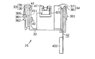
図3に示すように、ハウジング25の接合端面251の包囲領域内には取り付け凹部252が形成されている。取り付け凹部252には合成樹脂製の保持体31が嵌め込まれる。図5に示すように、保持体31は、基板部32と、基板部32の一側端部に連なる第1の保持部33と、基板部32の他側端部に連なる第2の保持部34とからなる。基板部32には挿通孔321が形成されている。挿通孔321には回転軸211が通される。
As shown in FIG. 3, a
第1の保持部33は、第1アーム35と、第1アーム35の先端から折曲反転する第2アーム36とからなる。第1アーム35には配置孔351が形成されている。又、第1アーム35の基端部には案内斜面352が形成されている。第2アーム36の先端部には案内斜面363が形成されている。図1(b)に示すように、第2アーム36には複数の押さえ片361及び複数の位置決め片362が形成されている。各押さえ片361の外面には、第2アーム36の基端側から先端側に向かうにつれて第1アーム35から徐々に離間する傾斜面364が形成されている。又、各押さえ片361の内面には押さえ突部365が形成されている。図5に示すように、第1の保持部33には一対のホール素子39,40(ホール素子40は図4に示す)を備えたセンサ基板41が装着される。ホール素子39,40は配置孔351から第1アーム35の内側へ突出している。センサ基板41は案内斜面352,363間から挿入される。
The
第2の保持部34は、内側アーム37と外側アーム38とからなる。外側アーム38の先端部には案内斜面383が形成されている。図2(b)に示すように、外側アーム38には押さえ片381及び位置決め片382が形成されている。
The
押さえ片381の外面には、外側アーム38の先端側から基端側に向かうにつれて内側アーム37から徐々に離間する傾斜面384が形成されている。又、押さえ片381の内面には押さえ突部385が形成されている。図5に示すように、第2の保持部34には遮断器42が装着される。遮断器42は案内斜面383と内側アーム37との間から挿入される。遮断器42は、バイメタル421及びコネクタ422を備えた焼損防止手段である。バイメタル421は遮断器42内の一対の導体(図示略)間の電気接続の入り切りを行なう。
An
図4は、センサ基板41及び遮断器42を装着した保持体31を取り付け凹部252に嵌め込んだ状態を示す。前記一対のブラシの一方は、図示しない配線を介してハウジング24の一部となるコネクタ部30内の一方の給電端子48に電気接続されている。遮断器42を装着した保持体31を取り付け凹部252に嵌め込んだ状態では、前記一対のブラシの他方は、図示しない配線、前記一対の導体、コネクタ422とハウジング25側のコネクタ43との接続、図示しない配線を介してハウジング24の一部となるコネクタ部30内の他方の給電端子48に電気接続されている。モータ本体21への電力供給は、コネクタ部30内の給電端子48、ブラシ及び整流子を介して行われる。遮断器42は、モータ本体21が過熱するとモータ本体21への給電を遮断する。
FIG. 4 shows a state where the holding
モータ本体21の回転軸211には回転状態検出用マグネット44が取り付けられている。センサ基板41を装着した保持体31を取り付け凹部252に嵌め込み、かつモータ本体21と出力部22とを結合した状態では、ホール素子39,40が回転状態検出用マグネット44の周囲に位置する。ホール素子39,40は、回転軸211の回転に伴う回転状態検出用マグネット44の周囲の磁界の変化を検出し、センサ基板41はホール素子39,40から得られる検出情報を検出電圧として出力する。一対のホール素子39,40の採用はモータ本体21の回転方向を検出するためである。
A rotation
コネクタ部30内には4本の回転状態検出用電気接続端子45が設けられており、ハウジング25の環状の接合端面251の包囲領域内には4本の回転状態検出用電気接続端子46が設けられている。回転状態検出用電気接続端子45と回転状態検出用電気接続端子46とは、ハウジング25内の図示しない配線を介して1対1に接続している。4本の回転状態検出用電気接続端子46の2本は給電用であり、残りの2本は前記検出電圧を外部のモータ制御装置へ出力するためのものである。
Four rotational state detecting
図6及び図7(a)に示すように、図5の状態からハウジング25の取り付け凹部252に保持体31を嵌め込んだ状態では、位置決め片362,382の先端が取り付け凹部252の位置決め凹部253に当接すると共に、回転状態検出用電気接続端子46がセンサ基板41と押さえ片361との間に配置される。センサ基板41と押さえ片361との間に配置された各回転状態検出用電気接続端子46は、センサ基板41上の4つの電気接続端子411(図では1つのみ示す)と1対1に対向する。
As shown in FIGS. 6 and 7A, in the state where the holding
図7(a)の状態からモータ本体21を出力部22に直接結合すると、図7(b)に示すように、モータ本体21のハウジング24の内壁面242が押さえ片361,381の傾斜面364,384に当接する。この当接作用により押さえ片361がセンサ基板41側に押されて弾性変形し、押さえ突部365が回転状態検出用電気接続端子46を電気接続端子411に押し付ける。この押しつけ作用により回転状態検出用電気接続端子46と電気接続端子411とが電気的に接続すると共に、センサ基板41が第1の保持部33にしっかりと保持される。又、前記当接作用により押さえ片381がバイメタル421側に押されて弾性変形し、押さえ突部385がバイメタル421を内側アーム37に押し付ける。この押しつけ作用により遮断器42が第2の保持部34にしっかりと保持される。
When the motor
第1の実施の形態では以下の効果が得られる。
(1−1)モータ本体21側のハウジング24の接合端面241と、出力部22側のハウジング25の接合端面251とを接合、即ちモータ本体21と出力部22とを直接に結合すれば、回転状態検出用電気接続端子46と電気接続端子411とが保持手段である保持体31の弾性変形作用によって電気的に確実に接続する。回転状態検出用電気接続端子46と電気接続端子411との確実な電気接続は、出力部22のハウジング25に対するねじ23の締め付けによって容易に達成される。
The following effects can be obtained in the first embodiment.
(1-1) If the joining
(1−2)モータ本体21と出力部22とを直接に結合すれば、電気装置であるセンサ基板41が保持体31の弾性変形作用によってハウジング24,25内で保持体31に確実に保持される。
(1-2) If the
(1−3)モータ本体21のハウジング24の環状の接合端面241と、端子内蔵部である出力部22のハウジング25の環状の接合端面251との接合は、モータ本体21と出力部22とを直接結合する。ハウジング24,25間の直接結合は、ハウジング24,25間のシール性の確保を容易にする。
(1-3) The joint between the annular
(1−4)押さえ片361は、モータ本体21のハウジング24との非干渉状態では、端子内蔵部である出力部22側の回転状態検出用電気接続端子46と電気装置であるセンサ基板41側の電気接続端子411とを電気的に接続しない位置にある。押さえ片361は、モータ本体21のハウジング24との干渉状態では、出力部22側の回転状態検出用電気接続端子46とセンサ基板41側の電気接続端子411とを電気的に接続する位置にある。出力部22側の回転状態検出用電気接続端子46とセンサ基板41側の電気接続端子411とは、電気接続手段となる押さえ片361の弾性変形によって確実に電気接続する。押さえ片361の弾性変形によって回転状態検出用電気接続端子46と電気接続端子411とを電気的に接続する構成は簡便である。
(1-4) In the non-interference state with the
(1−5)合成樹脂による保持体31の一体形成は、保持体31の製造を容易にする。
(1−6)回転状態検出用電気接続端子46と電気接続端子411との確実な電気接続に必要な押しつけ力よりも過大な押しつけ力で押さえ片361を付勢した場合にも、第1アーム35及び基板部32が弾性変形して前記の過大な押しつけ力を吸収する。第1アーム35及び基板部32が弾性変形しないとすると、前記の過大な押しつけ力を吸収することができず、保持体31が損傷する。この損傷を回避するにはモータ本体21のハウジング24と保持体31との間の組み付け精度を高くする必要がある。しかし、合成樹脂による保持体31の一体形成は、モータ本体21のハウジング24と保持体31との間の高い組み付け精度を必要とせず、保持体31の製造が容易になる。
(1-5) The integral formation of the holding
(1-6) Even when the
(1−7)出力部22は端子内蔵部として好適である。
(1−8)車両ドアに装着されるパワーウィンド装置の小型化の要求が強い。小型化の要求の強いパワーウィンド装置のモータは本発明の適用対象として好適である。
(1-7) The
(1-8) There is a strong demand for downsizing the power window device mounted on the vehicle door. A motor of a power window device that is strongly demanded for miniaturization is suitable as an application target of the present invention.
次に、図8及び図9の第2の実施の形態を説明する。第1の実施の形態と同じ構成部には同じ符号が付してある。
この実施の形態では、ブラシホルダ47が保持体31に一体形成されている。
Next, a second embodiment of FIGS. 8 and 9 will be described. The same components as those in the first embodiment are denoted by the same reference numerals.
In this embodiment, the
図示の例ではセンサ基板41及び遮断器42が保持体31に装着されている。このような一体構成は、ブラシホルダ47の組み付けを容易にする。
本発明では以下のような実施の形態も可能である。
(1)複数対の回転状態検出用電気接続端子46と電気接続端子411とを単一の押さえ片で電気接続させること。
(2)出力部22側のハウジング25との干渉によって回転状態検出用電気接続端子46と電気接続端子411とを電気接続する保持体を用いること。
(3)保持体を介してモータ本体21と出力部22とを間接に結合すること。例えば、ハウジング24側の接合端面241の全周とハウジング25側の接合端面251の全周との間に保持体の一部(例えば第1の実施の形態における位置決め片362,382に相当する部分)を介在すること。
(4)保持体を弾性のある金属で一体形成すること。
(5)押さえ片361,381を別体形成し、別体形成した押さえ片を脱落不能に保持体に組み付けて保持手段を構成すること。
(6)コネクタ422のない遮断器42を電気装置として保持体31に装着し、遮断器42側の電気接続端子と出力部22側の電気接続端子とを保持体31の弾性変形によって電気接続するように構成すること。
(7)パワーウィンド装置以外の駆動装置のモータ、例えばサンルーフ装置のモータに本発明を適用すること。
In the illustrated example, the
In the present invention, the following embodiments are also possible.
(1) Electrically connecting a plurality of pairs of rotation state detection
(2) Use a holding body that electrically connects the rotation state detecting
(3) The motor
(4) The holding body is integrally formed of an elastic metal.
(5) The holding pieces are formed by separately forming the holding
(6) The
(7) The present invention is applied to a motor of a drive device other than the power window device, for example, a motor of a sunroof device.
21…モータ本体。22…端子内蔵部となる出力部。24…モータ本体側のハウジング。25…出力部側のハウジング。31…保持手段となる保持体。361…電気接続手段となる押さえ片。41…電気装置となるセンサ基板。411…電気装置側の電気接続端子。46…端子内蔵部側の電気接続端子となる回転状態検出用電気接続端子。47…ブラシホルダ。 21 ... Motor body. 22: An output unit serving as a terminal built-in unit. 24 ... Housing on the motor body side. 25: A housing on the output side. 31: A holding body as a holding means. 361: A pressing piece serving as an electrical connection means. 41 ... A sensor substrate to be an electric device. 411: Electrical connection terminal on the electrical device side. 46. An electrical connection terminal for detecting the rotation state, which is an electrical connection terminal on the terminal built-in side. 47 ... Brush holder.
Claims (21)
回転軸の回転に伴う変化を検出するためのセンサを備えたセンサ基板を含む電気装置を保持する保持手段と、該保持手段及び前記センサ基板とは別体に設けられブラシを支持するブラシホルダとを有し、
前記モータ本体のハウジングと前記端子内蔵部のハウジングとが直接又は間接に結合される状態において前記端子内蔵部のハウジングにおける結合側となる接合端面の包囲領域内には、該端子内蔵部のハウジング内に凹む取り付け凹部が形成され、前記センサ基板及び前記保持手段は、前記取り付け凹部に対して前記回転軸の軸方向から嵌め込まれ、前記センサ基板及び前記保持手段が前記取り付け凹部に嵌め込まれた状態において前記センサ及び前記センサ基板は前記端子内蔵部のハウジングにおける接合端面の包囲領域内に配置され、前記保持手段及び前記ブラシホルダが前記端子内蔵部のハウジングに配置された状態で前記端子内蔵部のハウジングと前記モータ本体のハウジングとが結合された駆動装置用モータ。 A motor main body having a rotating shaft; and a terminal built-in portion containing an electric connection terminal, wherein the motor main body and the terminal built-in portion are directly or indirectly coupled to the housing of the motor main body and the housing of the terminal built-in portion. In a motor for a drive unit that integrates
A holding means for holding an electric device including a sensor substrate having a sensor for detecting a change associated with rotation of the rotating shaft; a brush holder provided separately from the holding means and the sensor substrate and supporting a brush; Have
In a state where the housing of the motor main body and the housing of the terminal built-in portion are directly or indirectly coupled, the enclosed area on the joining end surface on the coupling side of the housing of the terminal built-in portion has an inside of the housing of the terminal built-in portion. is mounting recess recessed in the formation, wherein the sensor substrate and said holding means, said are written because fitted axially or al of the rotary shaft relative to the mounting recess, the sensor substrate and said holding means is fitted into the mounting recess In this state, the sensor and the sensor substrate are disposed in a surrounding area of the joint end surface of the housing of the terminal built-in portion, and the holding means and the brush holder are disposed in the housing of the terminal built-in portion. A motor for a drive device in which a housing of the motor and a housing of the motor body are coupled.
前記取り付け凹部には前記保持手段のための位置決め部が形成された駆動装置用モータ。 The motor for a drive device according to claim 1,
A motor for a driving device in which a positioning portion for the holding means is formed in the mounting recess .
前記位置決め部は、前記取り付け凹部に前記保持手段が嵌め込まれた状態で該保持手段とその嵌め込み方向に当接して、前記端子内蔵部のハウジングに対する前記保持手段の嵌め込み方向の位置決めを可能とする駆動装置用モータ。 The motor for a driving device according to claim 2,
The positioning unit is configured to contact the holding unit in the fitting direction in a state in which the holding unit is fitted in the mounting recess, and to enable positioning of the holding unit in the fitting direction with respect to the housing of the terminal built-in unit. Equipment motor.
前記センサ基板は、前記センサの設けられる面が前記回転軸の軸方向に沿って配置されており、そのセンサ基板の配置状態において前記センサは前記回転軸側へ突出している駆動装置用モータ。 The motor for a driving device according to any one of claims 1 to 3,
The sensor board is a motor for a driving device in which a surface on which the sensor is provided is arranged along the axial direction of the rotation shaft, and the sensor protrudes toward the rotation shaft in the arrangement state of the sensor board .
前記センサ基板は、その平面が前記回転軸と平行となるように設置された駆動装置用モータ。 The motor for a drive device according to any one of claims 1 to 4,
The sensor substrate is a motor for a driving device installed so that a plane thereof is parallel to the rotation axis .
前記センサは、一対のホール素子であって、それらホール素子は、前記回転軸の軸方向の直角方向に沿って前記センサ基板の一平面上に並設された駆動装置用モータ。 In the motor for drive devices according to claim 5 ,
The sensor is a pair of Hall elements, and the Hall elements are arranged on a plane of the sensor substrate along a direction perpendicular to the axial direction of the rotating shaft .
前記センサ基板上には、回転状態検出用電気接続端子が電気的に接続される電気接続端子が設けられた駆動装置用モータ。 The motor for a driving device according to any one of claims 1 to 6,
A motor for a driving device provided with an electrical connection terminal to which a rotational state detection electrical connection terminal is electrically connected on the sensor substrate .
前記回転状態検出用電気接続端子と前記電気接続端子とが電気的に接続されると共に前記センサ基板が前記保持手段に保持された駆動装置用モータ。 The motor for a driving device according to claim 7,
A motor for a driving device in which the electrical connection terminal for rotation state detection and the electrical connection terminal are electrically connected and the sensor substrate is held by the holding means .
前記回転状態検出用電気接続端子と前記電気接続端子とは、前記センサ基板における前記センサの裏側で電気的に接続された駆動装置用モータ。 The motor for a driving device according to claim 7 or 8,
The rotation state detecting electrical connection terminal and the electrical connection terminal are motors for a driving device that are electrically connected on the back side of the sensor on the sensor substrate .
前記回転状態検出用電気接続端子は、その一部が前記保持手段によって支持された駆動装置用モータ。 The drive device motor according to any one of claims 7 to 9,
The rotation state detecting electrical connection terminal is a motor for a driving device, a part of which is supported by the holding means .
前記センサ基板が前記保持手段に保持された状態で、前記電気接続端子と前記回転状態検出用電気接続端子とが接続可能とされた駆動装置用モータ。 The motor for a drive device according to any one of claims 7 to 10,
A motor for a driving device in which the electrical connection terminal and the rotation state detection electrical connection terminal are connectable in a state where the sensor substrate is held by the holding means .
前記端子内蔵部のハウジングの一部にはコネクタ部が形成され、該コネクタ部内には前記電気装置と電気的に接続された回転状態検出用電気接続端子が設けられた駆動装置用モータ。 The motor for a driving device according to any one of claims 1 to 11,
A motor for a driving device in which a connector portion is formed in a part of the housing of the terminal built-in portion, and an electrical connection terminal for detecting a rotation state that is electrically connected to the electrical device is provided in the connector portion .
前記回転状態検出用電気接続端子は外部のモータ制御装置に電気的に接続するためのものである駆動装置用モータ。 The motor for a driving device according to claim 12 ,
The rotation state detecting electrical connection terminal is a motor for a driving device for electrically connecting to an external motor control device .
前記コネクタ部内には、ブラシと電気的に接続された給電端子が設けられた駆動装置用モータ。 The motor for a driving device according to claim 12 or 13 ,
A motor for a driving device in which a power supply terminal electrically connected to the brush is provided in the connector portion .
前記コネクタ部は、前記回転軸に対して直交する方向に向けて開口している駆動装置用モータ。 In the driving device for a motor according to any one of claims 1 2 to 14,
The connector unit is a motor for a driving device that is open toward a direction orthogonal to the rotation axis .
前記コネクタ部は、前記回転軸を挟んで出力軸の反対側に設けられた駆動装置用モータ。 The motor for a driving device according to any one of claims 12 to 15,
The connector portion is a motor for a driving device provided on the opposite side of the output shaft across the rotation shaft .
前記コネクタ部は、外径側に向けて突出した駆動装置用モータ。 The motor for a driving device according to any one of claims 12 to 16,
The connector portion is a motor for a driving device that protrudes toward the outer diameter side .
前記ブラシホルダは、前記モータ本体のハウジングと前記端子内蔵部のハウジングとが直接又は間接に結合される状態において前記モータ本体のハウジングにおける結合側となる接合端面の包囲領域内に設けられた駆動装置用モータ。 The drive motor according to any one of claims 1 to 17,
The brush holder is provided in a surrounding region of a joint end surface on a coupling side of the motor body housing in a state where the housing of the motor body and the housing of the terminal built-in portion are coupled directly or indirectly. Motor.
前記保持手段は合成樹脂製である駆動装置用モータ。 The motor for a drive device according to any one of claims 1 to 18,
The drive means motor is made of synthetic resin .
前記端子内蔵部は、前記モータ本体から出力される回転力を駆動対象に伝達する出力部である駆動装置用モータ。 The motor for a drive device according to any one of claims 1 to 19,
The terminal built-in unit is a motor for a driving device that is an output unit that transmits a rotational force output from the motor main body to a driving target .
前記出力部と共にパワーウィンド装置を構成するレギュレータを往復駆動する駆動装置用モータ。 The motor for a drive device according to claim 20 ,
A motor for a driving device that reciprocally drives a regulator that constitutes a power window device together with the output unit .
Priority Applications (1)
| Application Number | Priority Date | Filing Date | Title |
|---|---|---|---|
| JP2006053367A JP4397903B2 (en) | 2006-02-28 | 2006-02-28 | Motor for drive device |
Applications Claiming Priority (1)
| Application Number | Priority Date | Filing Date | Title |
|---|---|---|---|
| JP2006053367A JP4397903B2 (en) | 2006-02-28 | 2006-02-28 | Motor for drive device |
Related Parent Applications (1)
| Application Number | Title | Priority Date | Filing Date |
|---|---|---|---|
| JP27618799A Division JP4319300B2 (en) | 1999-09-29 | 1999-09-29 | Motor for drive device |
Publications (2)
| Publication Number | Publication Date |
|---|---|
| JP2006149197A JP2006149197A (en) | 2006-06-08 |
| JP4397903B2 true JP4397903B2 (en) | 2010-01-13 |
Family
ID=36628212
Family Applications (1)
| Application Number | Title | Priority Date | Filing Date |
|---|---|---|---|
| JP2006053367A Expired - Lifetime JP4397903B2 (en) | 2006-02-28 | 2006-02-28 | Motor for drive device |
Country Status (1)
| Country | Link |
|---|---|
| JP (1) | JP4397903B2 (en) |
Families Citing this family (1)
| Publication number | Priority date | Publication date | Assignee | Title |
|---|---|---|---|---|
| JP5664909B2 (en) * | 2011-01-28 | 2015-02-04 | 株式会社ジェイテクト | Electric motor unit |
-
2006
- 2006-02-28 JP JP2006053367A patent/JP4397903B2/en not_active Expired - Lifetime
Also Published As
| Publication number | Publication date |
|---|---|
| JP2006149197A (en) | 2006-06-08 |
Similar Documents
| Publication | Publication Date | Title |
|---|---|---|
| KR100909104B1 (en) | Motor, control circuit member of motor and manufacturing method of motor | |
| US6975059B2 (en) | Electric motor | |
| JP5745256B2 (en) | Motor drive device | |
| JP4774888B2 (en) | motor | |
| WO2007132624A1 (en) | Motor with reduction gear and method of manufacturing the same | |
| US8242648B2 (en) | Control circuit member and motor | |
| KR102566067B1 (en) | Electric machines including brush holding parts and plug modules | |
| JP5823165B2 (en) | Rotation detection device and motor | |
| JP2010288383A (en) | Electric motor including reduction gear mechanism | |
| CN103973047B (en) | The structure of brshless DC motor | |
| JP2009201277A (en) | Electric motor with speed reduction mechanism | |
| JP6809246B2 (en) | Motor device | |
| US20190252952A1 (en) | Motor | |
| JP4397903B2 (en) | Motor for drive device | |
| JP4397900B2 (en) | Motor for drive device | |
| JP4362421B2 (en) | motor | |
| JP6988093B2 (en) | Connection terminal, motor device and wiper motor device | |
| JP4397902B2 (en) | Motor for drive device | |
| JP4319300B2 (en) | Motor for drive device | |
| JP4397901B2 (en) | Motor for drive device | |
| JP4705415B2 (en) | Electric motor | |
| JP4397904B2 (en) | Manufacturing method of motor for driving device | |
| JP5399722B2 (en) | Control circuit member and motor | |
| JP4099032B2 (en) | motor | |
| JP2007174874A (en) | Method of manufacturing motor controller and method of manufacturing motor |
Legal Events
| Date | Code | Title | Description |
|---|---|---|---|
| A621 | Written request for application examination |
Free format text: JAPANESE INTERMEDIATE CODE: A621 Effective date: 20060228 |
|
| A131 | Notification of reasons for refusal |
Free format text: JAPANESE INTERMEDIATE CODE: A131 Effective date: 20081202 |
|
| A521 | Written amendment |
Free format text: JAPANESE INTERMEDIATE CODE: A523 Effective date: 20090202 |
|
| A131 | Notification of reasons for refusal |
Free format text: JAPANESE INTERMEDIATE CODE: A131 Effective date: 20090526 |
|
| A521 | Written amendment |
Free format text: JAPANESE INTERMEDIATE CODE: A523 Effective date: 20090626 |
|
| TRDD | Decision of grant or rejection written | ||
| A01 | Written decision to grant a patent or to grant a registration (utility model) |
Free format text: JAPANESE INTERMEDIATE CODE: A01 Effective date: 20091020 |
|
| A01 | Written decision to grant a patent or to grant a registration (utility model) |
Free format text: JAPANESE INTERMEDIATE CODE: A01 |
|
| A61 | First payment of annual fees (during grant procedure) |
Free format text: JAPANESE INTERMEDIATE CODE: A61 Effective date: 20091021 |
|
| FPAY | Renewal fee payment (event date is renewal date of database) |
Free format text: PAYMENT UNTIL: 20121030 Year of fee payment: 3 |
|
| R150 | Certificate of patent or registration of utility model |
Ref document number: 4397903 Country of ref document: JP Free format text: JAPANESE INTERMEDIATE CODE: R150 Free format text: JAPANESE INTERMEDIATE CODE: R150 |
|
| FPAY | Renewal fee payment (event date is renewal date of database) |
Free format text: PAYMENT UNTIL: 20121030 Year of fee payment: 3 |
|
| FPAY | Renewal fee payment (event date is renewal date of database) |
Free format text: PAYMENT UNTIL: 20131030 Year of fee payment: 4 |
|
| FPAY | Renewal fee payment (event date is renewal date of database) |
Free format text: PAYMENT UNTIL: 20141030 Year of fee payment: 5 |
|
| R250 | Receipt of annual fees |
Free format text: JAPANESE INTERMEDIATE CODE: R250 |
|
| R250 | Receipt of annual fees |
Free format text: JAPANESE INTERMEDIATE CODE: R250 |
|
| R250 | Receipt of annual fees |
Free format text: JAPANESE INTERMEDIATE CODE: R250 |
|
| R250 | Receipt of annual fees |
Free format text: JAPANESE INTERMEDIATE CODE: R250 |
|
| R157 | Certificate of patent or utility model (correction) |
Free format text: JAPANESE INTERMEDIATE CODE: R157 |
|
| S111 | Request for change of ownership or part of ownership |
Free format text: JAPANESE INTERMEDIATE CODE: R313111 |
|
| R360 | Written notification for declining of transfer of rights |
Free format text: JAPANESE INTERMEDIATE CODE: R360 |
|
| R360 | Written notification for declining of transfer of rights |
Free format text: JAPANESE INTERMEDIATE CODE: R360 |
|
| R371 | Transfer withdrawn |
Free format text: JAPANESE INTERMEDIATE CODE: R371 |
|
| S111 | Request for change of ownership or part of ownership |
Free format text: JAPANESE INTERMEDIATE CODE: R313111 |
|
| R350 | Written notification of registration of transfer |
Free format text: JAPANESE INTERMEDIATE CODE: R350 |
|
| R250 | Receipt of annual fees |
Free format text: JAPANESE INTERMEDIATE CODE: R250 |
|
| EXPY | Cancellation because of completion of term |