JP4396418B2 - Filling equipment - Google Patents
Filling equipment Download PDFInfo
- Publication number
- JP4396418B2 JP4396418B2 JP2004189283A JP2004189283A JP4396418B2 JP 4396418 B2 JP4396418 B2 JP 4396418B2 JP 2004189283 A JP2004189283 A JP 2004189283A JP 2004189283 A JP2004189283 A JP 2004189283A JP 4396418 B2 JP4396418 B2 JP 4396418B2
- Authority
- JP
- Japan
- Prior art keywords
- filling
- nozzle
- container
- filling nozzle
- mounting portion
- Prior art date
- Legal status (The legal status is an assumption and is not a legal conclusion. Google has not performed a legal analysis and makes no representation as to the accuracy of the status listed.)
- Expired - Fee Related
Links
Images


Description
本発明は、アイソレータなど無菌雰囲気が維持された空間内で、上方からラミナフローを吹き付けながら充填を行う充填装置に係り、特に、その充填ノズルの形状に関するものである。 The present invention relates to a filling apparatus that performs filling while blowing a laminar flow from above in a space where an aseptic atmosphere such as an isolator is maintained, and particularly relates to the shape of the filling nozzle.
従来の充填装置に設けられた充填ノズルは一般に、容器を搬送する搬送経路の真上に、垂直に配置されている。例えば、特許文献1に示す構成では、アンプルを移送するための移送装置の上方に配置した針保持具が複数本(この例では6本)の針(本発明の充填ノズルに相当する)を収容している。それぞれの針は、管状針部分と針アタッチメントとを有している。針保持具は、前記複数の針部分を収容する平行なV字形の溝を備えた保持プレートを有しており、各針をV字状の溝内にそれぞれ配置し、一本ずつ締め付けプレートで押さえて、蝶ナットによって固定している。
In general, a filling nozzle provided in a conventional filling apparatus is vertically disposed directly above a conveyance path for conveying a container. For example, in the configuration shown in
前記充填装置の針(充填ノズル)は、容器を搬送する搬送経路の真上に、垂直に配置されている。つまり、アンプル(容器)内に内容物を充填する管状針部分の吐出口が容器の軸線に一致して配置されるとともに、その上部を固定する針保持具がその吐出口の真上に位置している。
前記従来の充填装置では、針(充填ノズル)が直線状であり、容器の真上に固定用のナットなどの異物を発生させる可能性のある部材が配置してあるため、容器内に異物が入り込むおそれがある。また、アイソレータなどの無菌空間内で充填を行う際に、上方からラミナフローを行い、塵などが舞い上がらないように押さえ込むようにしているが、容器の真上にナット等の充填ノズルの固定具があるため、ラミナフローの流れの妨げとなり、塵などが充填位置付近に浮遊するおそれがある。 In the conventional filling device, the needle (filling nozzle) is linear, and a member that may generate foreign matter such as a fixing nut is disposed directly above the container. There is a risk of getting in. In addition, when filling in an aseptic space such as an isolator, laminar flow is performed from above, so that dust does not rise, but there is a filling nozzle fixture such as a nut directly above the container. As a result, the laminar flow is hindered and dust may float near the filling position.
本発明は、容器を充填位置に供給する容器供給手段と、充填位置に設けられ、容器内に充填する充填物を吐出する吐出口を有する充填ノズルとを備え、上方から下方へ向けてエアを吹き付けるラミナフローが行われる雰囲気下の室内に設置される充填装置において、前記充填ノズルの取付部が係合する溝を有するノズルホルダと、このノズルホルダの溝に充填ノズルを係合させて固定する固定手段とを備え、充填ノズルの取付部を前記ノズルホルダの溝に合致する形状とし、前記充填ノズルを湾曲させ、前記取付部を水平な状態で前記ノズルホルダの溝内に保持させるとともに、前記充填ノズルの吐出口を充填位置に供給される容器の軸心と一致させて配置したことを特徴とするものである。 The present invention comprises a container supply means for supplying a container to a filling position, and a filling nozzle provided at the filling position and having a discharge port for discharging a filling material filled in the container, and air is supplied from above to below. In a filling apparatus installed in a room under an atmosphere where laminar flow is performed , a nozzle holder having a groove with which the mounting portion of the filling nozzle is engaged, and fixing for engaging and fixing the filling nozzle in the groove of the nozzle holder A mounting portion of the filling nozzle that matches the groove of the nozzle holder, the filling nozzle is curved, and the mounting portion is held in the groove of the nozzle holder in a horizontal state. The discharge port of the nozzle is arranged so as to coincide with the axis of the container supplied to the filling position.
本発明の充填装置は、充填ノズルの吐出口を充填位置の容器の軸心にほぼ一致させるとともに、この充填ノズルを湾曲させているため、充填ノズルの取付部が前記充填位置の容器の真上からずれているので、充填位置に供給された容器の上方で微小な異物が発生する可能性を除き、かつ、ラミナフローによる空気の流れを妨げることなく、充填位置の容器の周囲に塵等が浮遊することを防止できる。 In the filling device of the present invention, the discharge port of the filling nozzle is substantially aligned with the axial center of the container at the filling position, and the filling nozzle is curved, so that the mounting portion of the filling nozzle is directly above the container at the filling position. Since there is a deviation from the above, there is no possibility that a minute foreign matter is generated above the container supplied to the filling position, and dust etc. is floated around the container at the filling position without disturbing the air flow due to the laminar flow. Can be prevented.
充填ノズルの充填物を吐出する吐出口を、充填位置に供給された容器の軸心に一致させるとともに、この充填ノズルを湾曲させ、充填ノズルの取付部を容器の真上から外れた位置に配置するという構成で、ラミナフローを妨げることなく、塵等が容器の周囲を浮遊しないようにするという目的を達成する。 The discharge port for discharging the filling material of the filling nozzle is aligned with the axial center of the container supplied to the filling position, the filling nozzle is curved, and the mounting portion of the filling nozzle is arranged at a position off from directly above the container. With this configuration, the object of preventing dust and the like from floating around the container without interfering with laminar flow is achieved.
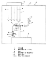
以下、図面に示す実施例により本発明を説明する。図1は、本発明の一実施例に係る充填装置の全体の構成を示す断面図である。この充填装置は、アイソレータ2内に設置されており、無菌雰囲気内で充填を行うようになっている。アイソレータ2内に設置されたベース4上に直線状のレール6が配置され、このレール6上に載せられた容器8が搬送手段10によって一列で搬送され、以下に説明する充填ノズル12が配置された充填位置Aに供給される。前記レール6および搬送手段10によって、請求項1の容器供給手段が構成されている。
Hereinafter, the present invention will be described with reference to embodiments shown in the drawings. FIG. 1 is a cross-sectional view showing the overall configuration of a filling apparatus according to an embodiment of the present invention. This filling device is installed in the
前記アイソレータ2の天井2aには、ラミナフロー発生手段14が設けられており、上方から下方へ向けて無菌エアを吹き出し(図1の矢印B参照)、充填位置A付近で塵等が舞い上がって容器8内に侵入することを防止するようになっている。
Laminar flow generating means 14 is provided on the
前記ベース4上には、複数の充填ノズル12を取り付けるノズル支持台16が直立して固定されている。このノズル支持台16は、直線状に配置されたレール6と平行して複数の充填ノズル12を支持するように(図2参照)、レール6と平行に固定されている。ノズル支持台16の上端に、充填ノズル12を保持するノズル取付手段18が設けられている。このノズル取付手段18は、充填ノズル12の下側を支持するノズルホルダ20と、充填ノズル12の上側を抑えて固定する固定手段22から成っている。固定手段22は、一端部側が連結された支点24aを中心にして回動可能な押さえレバー24と、この押さえレバー24の回動端24bをノズルホルダ20の端部に締結する固定ボルト26aを有するクランプ26とを備えている。
On the base 4, a
ノズルホルダ20の上面には、等間隔で複数個所(この実施例では8個所)のV字状の溝20aが形成されている。一方、このV字状の溝20a内に保持される充填ノズル12は、図1に示すように、充填ノズル取付手段18に保持される取付部12aと、容器8内に充填を行う吐出口12bを有する先端部12c側とがほぼ90度の角度で折り曲げられており、前記取付部12aを水平な状態でノズル取付手段18のV字状の溝20a内に保持させるようになっている。このように充填ノズル12の取付部12aを水平な状態で保持すると、吐出口12bを有する先端部12c側が鉛直方向を向くようになっている。
A plurality of V-shaped grooves 20a (eight locations in this embodiment) are formed at equal intervals on the upper surface of the
充填ノズル12の取付部12aは、前記ノズルホルダ20のV字状の溝20aに合致する角形状に形成されており、この取付部12aをノズルホルダ20のV字状溝20aに嵌合させると、この充填ノズル12の吐出口12bを有する先端部12c側を正確に位置決めすることができる。従って、充填ノズル12の吐出口12bを充填位置Aに供給された容器8の軸線に一致させることが可能になる。
The mounting portion 12a of the
充填ノズル取付手段18に充填ノズル12を取り付ける場合には、ノズルホルダ20の8個所のV字状の溝20a内にそれぞれ充填ノズル12の取付部12aを嵌合させ、その上面側に弾性を有するシリコンゴム28を配置するようになっている。この実施例では、シリコンゴム28が前記固定手段22の押さえレバー24に取り付けられており、押さえレバー24を回転させてこのシリコンゴム28を充填ノズル12の取付部12aとノズルホルダ20上に載せ、クランプ26により締結することによって8本の充填ノズル12を正確に位置決めして固定することができる。また、充填ノズル12を交換する場合にも、クランプ26をゆるめて押さえレバー24を回転させて立ち上げる(図2の想像線参照)ことによりすべての充填ノズル12を同時に交換することが可能であり、極めて作業性がよい。
When the
前記充填ノズル12は、取付部12aの上流側に開閉バルブ30を有する給液パイプ32が接続され、図示しないタンクから供給された充填液を、前記先端部12cの吐出口12bから容器8内に充填する。
The
この実施例では、充填ノズル12の吐出口12bを有する先端部12c側と、充填ノズル取付手段18に保持される取付部12aとをほぼ90度の角度に折り曲げてあり、先端部12c側を鉛直に配置するとともに、取付部12aを水平な状態でノズル取付手段18に保持させている。従って、充填位置Aに供給された容器8の真上には、吐出口12bを有する充填ノズル12の先端部12cだけが位置して、取付部12a等は容器8の真上から外れた位置に配置されているので、ラミナフローの下降気流Bがノズル取付手段18等によって阻害されることがなく、内容物が充填される容器8の周囲に塵等の異物が浮遊することがない。また、ノズル取付手段18のボルト26a等から発生する微小な異物が容器8上に落下するおそれもない。さらに、前記充填ノズル取付手段18のノズルホルダ20と、固定手段22の押さえレバー24の間にシリコンゴム28等の弾性部材を介在させているので、充填ノズル12の先端部12c側に、容器搬送方向の衝撃があった場合でも、シリコンゴム28の弾性分だけ充填ノズル12が逃げることができるため、充填ノズル12の損傷を防止することができる。また、複数の充填ノズル12を、ノズルホルダ20と固定手段22の押さえレバー24とで挟持し、一つのクランプ26で固定しているので、交換する場合にも、一個所のクランプ26を緩めるだけで、一度に全ての充填ノズル12を取り外し、別の充填ノズルを取り付けることができる。
In this embodiment, the
図4は、第2の実施例に係る充填装置の要部(充填ノズル取付手段118に取り付けられた充填ノズル112)を示す図である。前記第1実施例では、充填ノズル12の吐出口12bを有する先端部12c側と、充填ノズル取付手段18に保持される取付部12aとがほぼ90度の角度に折り曲げられ、先端部12c側が鉛直方向を向き、取付部12aは水平状態でノズルホルダ20に保持されていたが、この第2実施例では、充填ノズル112の吐出口112bを有する先端部112c側が鉛直方向を向き、その上部112dがほぼ90度の角度に折り曲げられて水平部を構成し、さらにその上部側に設けられた取付部112aがほぼ90度の角度に折り曲げられて鉛直方向を向いている。
FIG. 4 is a view showing a main part (a filling
従って、この実施例の充填ノズル112は、縦方向を向いた取付部112aが、横向きに配置された充填ノズル取付手段118に保持されるようになっている。この充填ノズル取付手段118は、ノズルホルダ120の上面ではなく、側面にV字状の溝(図示せず)が形成され、横方向に回動するレバー124によって前記充填ノズル112の取付部112aを保持するようになっている。この実施例でも、前記第1実施例と同様に、充填ノズル112の吐出口112bが充填位置Aの容器8の軸心に一致するように配置すると、充填ノズル112の取付部112a等は容器8の真上から外れるので、第1実施例と同様の効果を奏することができる。なお、充填ノズル112の吐出口112bを有する先端部112c側とその上部側112dとを必ずしも90度の角度に折り曲げる必要はなく、先端部112c側と上部とを湾曲させて吐出口112bの真上に取付部112aおよび充填ノズル取付手段118等が位置しないようにすればよい。
Accordingly, in the filling
A 充填位置
6 容器供給手段(レール)
8 容器
10 容器供給手段(搬送手段)
12 充填ノズル
12b 充填ノズルの吐出口
A Filling position 6 Container supply means (rail)
8
12
Claims (4)
前記充填ノズルの取付部が係合する溝を有するノズルホルダと、このノズルホルダの溝に充填ノズルを係合させて固定する固定手段とを備え、充填ノズルの取付部を前記ノズルホルダの溝に合致する形状とし、前記充填ノズルを湾曲させ、前記取付部を水平な状態で前記ノズルホルダの溝内に保持させるとともに、前記充填ノズルの吐出口を充填位置に供給される容器の軸心と一致させて配置したことを特徴とする充填装置。 A laminar flow that blows air from the top to the bottom is performed, including a container supply means for supplying the container to the filling position and a filling nozzle provided at the filling position and having a discharge port for discharging the filling material filled in the container. In a filling device installed in a room under a certain atmosphere,
A nozzle holder having a groove with which the mounting portion of the filling nozzle is engaged, and a fixing means for engaging and fixing the filling nozzle with the groove of the nozzle holder, the mounting portion of the filling nozzle being in the groove of the nozzle holder The filling nozzle is curved, the mounting portion is held in the groove of the nozzle holder in a horizontal state, and the discharge port of the filling nozzle coincides with the axis of the container supplied to the filling position. A filling device characterized by being arranged.
Priority Applications (1)
| Application Number | Priority Date | Filing Date | Title |
|---|---|---|---|
| JP2004189283A JP4396418B2 (en) | 2004-06-28 | 2004-06-28 | Filling equipment |
Applications Claiming Priority (1)
| Application Number | Priority Date | Filing Date | Title |
|---|---|---|---|
| JP2004189283A JP4396418B2 (en) | 2004-06-28 | 2004-06-28 | Filling equipment |
Publications (2)
| Publication Number | Publication Date |
|---|---|
| JP2006008195A JP2006008195A (en) | 2006-01-12 |
| JP4396418B2 true JP4396418B2 (en) | 2010-01-13 |
Family
ID=35775865
Family Applications (1)
| Application Number | Title | Priority Date | Filing Date |
|---|---|---|---|
| JP2004189283A Expired - Fee Related JP4396418B2 (en) | 2004-06-28 | 2004-06-28 | Filling equipment |
Country Status (1)
| Country | Link |
|---|---|
| JP (1) | JP4396418B2 (en) |
Family Cites Families (10)
| Publication number | Priority date | Publication date | Assignee | Title |
|---|---|---|---|---|
| JPH0542080Y2 (en) * | 1986-08-20 | 1993-10-22 | ||
| JP2853240B2 (en) * | 1990-02-20 | 1999-02-03 | 澁谷工業株式会社 | Filling device |
| JPH0630587U (en) * | 1992-09-24 | 1994-04-22 | 豊田合成株式会社 | Pipe clamp |
| IT1263451B (en) * | 1993-07-01 | 1996-08-05 | Ima Spa | AUTOMATIC MACHINE, CAROUSEL, FOR THE DOSAGE AND PACKAGING OF FLUID PRODUCTS, WITH DOSERS DISCONNECTED FROM THE CAROUSEL ITSELF AND EASILY INSPECTION. |
| JP3483298B2 (en) * | 1994-04-14 | 2004-01-06 | 澁谷工業株式会社 | Rotary body sealing device in container processing equipment |
| JP3460415B2 (en) * | 1995-10-16 | 2003-10-27 | 澁谷工業株式会社 | Aseptic filling device |
| JP3931242B2 (en) * | 1997-04-17 | 2007-06-13 | 澁谷工業株式会社 | Nozzle pipe mounting structure |
| JP3055910U (en) * | 1998-07-16 | 1999-02-02 | 東京ガスケット工業株式会社 | Wiring and piping clips |
| JP2002346808A (en) * | 2001-03-19 | 2002-12-04 | Suzuki Seiko:Kk | Cutter unit for lathe |
| DE10212008A1 (en) * | 2002-03-18 | 2003-10-09 | Aventis Behring Gmbh | needle holder |
-
2004
- 2004-06-28 JP JP2004189283A patent/JP4396418B2/en not_active Expired - Fee Related
Also Published As
| Publication number | Publication date |
|---|---|
| JP2006008195A (en) | 2006-01-12 |
Similar Documents
| Publication | Publication Date | Title |
|---|---|---|
| US7743907B2 (en) | Transport system for container processing machines | |
| ES2330807T3 (en) | CLEANING DEVICE FOR FILLING MACHINE. | |
| US8024909B2 (en) | Beverage bottling plant for filling bottles with a liquid beverage filling material having a receiving table for the container handling machines therein | |
| KR102000953B1 (en) | Capillary transfer device, capillary mounting device, capillary exchange device, capillary transfer method, capillary mounting method, and capillary exchange method | |
| WO2004100254A1 (en) | Substrate suction device | |
| JP4396418B2 (en) | Filling equipment | |
| KR100846823B1 (en) | Welding apparatus type one body nut supply machine | |
| JP4358924B2 (en) | Storage unit and storage device for plate-like substrate | |
| KR101177926B1 (en) | Vacuum sticking device | |
| JP2009176765A (en) | Article to be transported and vibration proof mechanism | |
| TWI816810B (en) | Storage rack | |
| US250500A (en) | Compound bottling-machine | |
| JP2016219537A (en) | Purge device and purge stocker | |
| JP2011136802A (en) | Carrying device | |
| US20110108161A1 (en) | Suspended delivery device and a container-filler installation including such devices | |
| CN112925174A (en) | Semiconductor lithographic apparatus | |
| JP4565520B1 (en) | Plate-shaped body transfer device | |
| CN113247623A (en) | Suspension transportation device and laser processing device | |
| JP4337622B2 (en) | Substrate underlay device | |
| JP2005343521A (en) | Cap feeding apparatus | |
| ATE281401T1 (en) | DEVICE FOR ALIGNING CORKS | |
| JP2007123408A (en) | Suction head | |
| JP2000165070A (en) | Plate-shaped substrate containing unit and containing apparatus | |
| JP2005145633A (en) | Air conveyance device | |
| JP4790279B2 (en) | Sheet material conveying method and sheet material conveying apparatus |
Legal Events
| Date | Code | Title | Description |
|---|---|---|---|
| A621 | Written request for application examination |
Free format text: JAPANESE INTERMEDIATE CODE: A621 Effective date: 20061030 |
|
| A977 | Report on retrieval |
Free format text: JAPANESE INTERMEDIATE CODE: A971007 Effective date: 20090212 |
|
| A131 | Notification of reasons for refusal |
Free format text: JAPANESE INTERMEDIATE CODE: A131 Effective date: 20090317 |
|
| A521 | Written amendment |
Free format text: JAPANESE INTERMEDIATE CODE: A523 Effective date: 20090518 |
|
| TRDD | Decision of grant or rejection written | ||
| A01 | Written decision to grant a patent or to grant a registration (utility model) |
Free format text: JAPANESE INTERMEDIATE CODE: A01 Effective date: 20090929 |
|
| A01 | Written decision to grant a patent or to grant a registration (utility model) |
Free format text: JAPANESE INTERMEDIATE CODE: A01 |
|
| A61 | First payment of annual fees (during grant procedure) |
Free format text: JAPANESE INTERMEDIATE CODE: A61 Effective date: 20091012 |
|
| FPAY | Renewal fee payment (event date is renewal date of database) |
Free format text: PAYMENT UNTIL: 20121030 Year of fee payment: 3 |
|
| R150 | Certificate of patent or registration of utility model |
Free format text: JAPANESE INTERMEDIATE CODE: R150 |
|
| FPAY | Renewal fee payment (event date is renewal date of database) |
Free format text: PAYMENT UNTIL: 20131030 Year of fee payment: 4 |
|
| LAPS | Cancellation because of no payment of annual fees |