JP4394802B2 - High-pressure gas cooling system for automotive air conditioners - Google Patents
High-pressure gas cooling system for automotive air conditioners Download PDFInfo
- Publication number
- JP4394802B2 JP4394802B2 JP2000123063A JP2000123063A JP4394802B2 JP 4394802 B2 JP4394802 B2 JP 4394802B2 JP 2000123063 A JP2000123063 A JP 2000123063A JP 2000123063 A JP2000123063 A JP 2000123063A JP 4394802 B2 JP4394802 B2 JP 4394802B2
- Authority
- JP
- Japan
- Prior art keywords
- heat exchange
- pressure side
- cooling device
- gas cooling
- manifold
- Prior art date
- Legal status (The legal status is an assumption and is not a legal conclusion. Google has not performed a legal analysis and makes no representation as to the accuracy of the status listed.)
- Expired - Fee Related
Links
- 238000001816 cooling Methods 0.000 title claims description 49
- 239000003507 refrigerant Substances 0.000 claims description 52
- 239000007791 liquid phase Substances 0.000 claims description 15
- 238000000926 separation method Methods 0.000 claims description 13
- 239000010687 lubricating oil Substances 0.000 claims description 6
- 238000004891 communication Methods 0.000 claims description 3
- 229910052751 metal Inorganic materials 0.000 claims description 2
- 239000002184 metal Substances 0.000 claims description 2
- 230000003134 recirculating effect Effects 0.000 claims 1
- 239000003570 air Substances 0.000 description 17
- 239000012071 phase Substances 0.000 description 9
- 238000005219 brazing Methods 0.000 description 8
- 238000006116 polymerization reaction Methods 0.000 description 3
- CURLTUGMZLYLDI-UHFFFAOYSA-N Carbon dioxide Chemical compound O=C=O CURLTUGMZLYLDI-UHFFFAOYSA-N 0.000 description 2
- 238000009825 accumulation Methods 0.000 description 2
- 229910002092 carbon dioxide Inorganic materials 0.000 description 2
- 238000010586 diagram Methods 0.000 description 2
- 238000001125 extrusion Methods 0.000 description 2
- 238000009434 installation Methods 0.000 description 2
- 230000002093 peripheral effect Effects 0.000 description 2
- 238000007747 plating Methods 0.000 description 2
- 229910000838 Al alloy Inorganic materials 0.000 description 1
- 238000004378 air conditioning Methods 0.000 description 1
- 229910052782 aluminium Inorganic materials 0.000 description 1
- XAGFODPZIPBFFR-UHFFFAOYSA-N aluminium Chemical compound [Al] XAGFODPZIPBFFR-UHFFFAOYSA-N 0.000 description 1
- 239000012080 ambient air Substances 0.000 description 1
- 239000001569 carbon dioxide Substances 0.000 description 1
- 239000003795 chemical substances by application Substances 0.000 description 1
- 230000001419 dependent effect Effects 0.000 description 1
- 238000004512 die casting Methods 0.000 description 1
- 238000009826 distribution Methods 0.000 description 1
- 230000000694 effects Effects 0.000 description 1
- 238000005516 engineering process Methods 0.000 description 1
- 239000007788 liquid Substances 0.000 description 1
- 238000004519 manufacturing process Methods 0.000 description 1
- 239000000463 material Substances 0.000 description 1
- 238000000034 method Methods 0.000 description 1
- 238000000465 moulding Methods 0.000 description 1
- 230000002265 prevention Effects 0.000 description 1
Images


Classifications
-
- F—MECHANICAL ENGINEERING; LIGHTING; HEATING; WEAPONS; BLASTING
- F28—HEAT EXCHANGE IN GENERAL
- F28D—HEAT-EXCHANGE APPARATUS, NOT PROVIDED FOR IN ANOTHER SUBCLASS, IN WHICH THE HEAT-EXCHANGE MEDIA DO NOT COME INTO DIRECT CONTACT
- F28D7/00—Heat-exchange apparatus having stationary tubular conduit assemblies for both heat-exchange media, the media being in contact with different sides of a conduit wall
- F28D7/0008—Heat-exchange apparatus having stationary tubular conduit assemblies for both heat-exchange media, the media being in contact with different sides of a conduit wall the conduits for one medium being in heat conductive contact with the conduits for the other medium
-
- B—PERFORMING OPERATIONS; TRANSPORTING
- B60—VEHICLES IN GENERAL
- B60H—ARRANGEMENTS OF HEATING, COOLING, VENTILATING OR OTHER AIR-TREATING DEVICES SPECIALLY ADAPTED FOR PASSENGER OR GOODS SPACES OF VEHICLES
- B60H1/00—Heating, cooling or ventilating [HVAC] devices
- B60H1/32—Cooling devices
- B60H1/3204—Cooling devices using compression
- B60H1/3227—Cooling devices using compression characterised by the arrangement or the type of heat exchanger, e.g. condenser, evaporator
-
- F—MECHANICAL ENGINEERING; LIGHTING; HEATING; WEAPONS; BLASTING
- F25—REFRIGERATION OR COOLING; COMBINED HEATING AND REFRIGERATION SYSTEMS; HEAT PUMP SYSTEMS; MANUFACTURE OR STORAGE OF ICE; LIQUEFACTION SOLIDIFICATION OF GASES
- F25B—REFRIGERATION MACHINES, PLANTS OR SYSTEMS; COMBINED HEATING AND REFRIGERATION SYSTEMS; HEAT PUMP SYSTEMS
- F25B40/00—Subcoolers, desuperheaters or superheaters
-
- F—MECHANICAL ENGINEERING; LIGHTING; HEATING; WEAPONS; BLASTING
- F25—REFRIGERATION OR COOLING; COMBINED HEATING AND REFRIGERATION SYSTEMS; HEAT PUMP SYSTEMS; MANUFACTURE OR STORAGE OF ICE; LIQUEFACTION SOLIDIFICATION OF GASES
- F25B—REFRIGERATION MACHINES, PLANTS OR SYSTEMS; COMBINED HEATING AND REFRIGERATION SYSTEMS; HEAT PUMP SYSTEMS
- F25B43/00—Arrangements for separating or purifying gases or liquids; Arrangements for vaporising the residuum of liquid refrigerant, e.g. by heat
- F25B43/006—Accumulators
-
- F—MECHANICAL ENGINEERING; LIGHTING; HEATING; WEAPONS; BLASTING
- F28—HEAT EXCHANGE IN GENERAL
- F28D—HEAT-EXCHANGE APPARATUS, NOT PROVIDED FOR IN ANOTHER SUBCLASS, IN WHICH THE HEAT-EXCHANGE MEDIA DO NOT COME INTO DIRECT CONTACT
- F28D1/00—Heat-exchange apparatus having stationary conduit assemblies for one heat-exchange medium only, the media being in contact with different sides of the conduit wall, in which the other heat-exchange medium is a large body of fluid, e.g. domestic or motor car radiators
- F28D1/02—Heat-exchange apparatus having stationary conduit assemblies for one heat-exchange medium only, the media being in contact with different sides of the conduit wall, in which the other heat-exchange medium is a large body of fluid, e.g. domestic or motor car radiators with heat-exchange conduits immersed in the body of fluid
- F28D1/04—Heat-exchange apparatus having stationary conduit assemblies for one heat-exchange medium only, the media being in contact with different sides of the conduit wall, in which the other heat-exchange medium is a large body of fluid, e.g. domestic or motor car radiators with heat-exchange conduits immersed in the body of fluid with tubular conduits
- F28D1/0408—Multi-circuit heat exchangers, e.g. integrating different heat exchange sections in the same unit or heat exchangers for more than two fluids
- F28D1/0417—Multi-circuit heat exchangers, e.g. integrating different heat exchange sections in the same unit or heat exchangers for more than two fluids with particular circuits for the same heat exchange medium, e.g. with the heat exchange medium flowing through sections having different heat exchange capacities or for heating/cooling the heat exchange medium at different temperatures
-
- F—MECHANICAL ENGINEERING; LIGHTING; HEATING; WEAPONS; BLASTING
- F28—HEAT EXCHANGE IN GENERAL
- F28D—HEAT-EXCHANGE APPARATUS, NOT PROVIDED FOR IN ANOTHER SUBCLASS, IN WHICH THE HEAT-EXCHANGE MEDIA DO NOT COME INTO DIRECT CONTACT
- F28D1/00—Heat-exchange apparatus having stationary conduit assemblies for one heat-exchange medium only, the media being in contact with different sides of the conduit wall, in which the other heat-exchange medium is a large body of fluid, e.g. domestic or motor car radiators
- F28D1/02—Heat-exchange apparatus having stationary conduit assemblies for one heat-exchange medium only, the media being in contact with different sides of the conduit wall, in which the other heat-exchange medium is a large body of fluid, e.g. domestic or motor car radiators with heat-exchange conduits immersed in the body of fluid
- F28D1/04—Heat-exchange apparatus having stationary conduit assemblies for one heat-exchange medium only, the media being in contact with different sides of the conduit wall, in which the other heat-exchange medium is a large body of fluid, e.g. domestic or motor car radiators with heat-exchange conduits immersed in the body of fluid with tubular conduits
- F28D1/0408—Multi-circuit heat exchangers, e.g. integrating different heat exchange sections in the same unit or heat exchangers for more than two fluids
- F28D1/0461—Combination of different types of heat exchanger, e.g. radiator combined with tube-and-shell heat exchanger; Arrangement of conduits for heat exchange between at least two media and for heat exchange between at least one medium and the large body of fluid
-
- F—MECHANICAL ENGINEERING; LIGHTING; HEATING; WEAPONS; BLASTING
- F28—HEAT EXCHANGE IN GENERAL
- F28F—DETAILS OF HEAT-EXCHANGE AND HEAT-TRANSFER APPARATUS, OF GENERAL APPLICATION
- F28F9/00—Casings; Header boxes; Auxiliary supports for elements; Auxiliary members within casings
- F28F9/02—Header boxes; End plates
- F28F9/0202—Header boxes having their inner space divided by partitions
- F28F9/0204—Header boxes having their inner space divided by partitions for elongated header box, e.g. with transversal and longitudinal partitions
- F28F9/0209—Header boxes having their inner space divided by partitions for elongated header box, e.g. with transversal and longitudinal partitions having only transversal partitions
- F28F9/0212—Header boxes having their inner space divided by partitions for elongated header box, e.g. with transversal and longitudinal partitions having only transversal partitions the partitions being separate elements attached to header boxes
-
- F—MECHANICAL ENGINEERING; LIGHTING; HEATING; WEAPONS; BLASTING
- F28—HEAT EXCHANGE IN GENERAL
- F28F—DETAILS OF HEAT-EXCHANGE AND HEAT-TRANSFER APPARATUS, OF GENERAL APPLICATION
- F28F9/00—Casings; Header boxes; Auxiliary supports for elements; Auxiliary members within casings
- F28F9/02—Header boxes; End plates
- F28F9/0202—Header boxes having their inner space divided by partitions
- F28F9/0204—Header boxes having their inner space divided by partitions for elongated header box, e.g. with transversal and longitudinal partitions
- F28F9/0214—Header boxes having their inner space divided by partitions for elongated header box, e.g. with transversal and longitudinal partitions having only longitudinal partitions
-
- F—MECHANICAL ENGINEERING; LIGHTING; HEATING; WEAPONS; BLASTING
- F25—REFRIGERATION OR COOLING; COMBINED HEATING AND REFRIGERATION SYSTEMS; HEAT PUMP SYSTEMS; MANUFACTURE OR STORAGE OF ICE; LIQUEFACTION SOLIDIFICATION OF GASES
- F25B—REFRIGERATION MACHINES, PLANTS OR SYSTEMS; COMBINED HEATING AND REFRIGERATION SYSTEMS; HEAT PUMP SYSTEMS
- F25B2309/00—Gas cycle refrigeration machines
- F25B2309/06—Compression machines, plants or systems characterised by the refrigerant being carbon dioxide
- F25B2309/061—Compression machines, plants or systems characterised by the refrigerant being carbon dioxide with cycle highest pressure above the supercritical pressure
-
- F—MECHANICAL ENGINEERING; LIGHTING; HEATING; WEAPONS; BLASTING
- F25—REFRIGERATION OR COOLING; COMBINED HEATING AND REFRIGERATION SYSTEMS; HEAT PUMP SYSTEMS; MANUFACTURE OR STORAGE OF ICE; LIQUEFACTION SOLIDIFICATION OF GASES
- F25B—REFRIGERATION MACHINES, PLANTS OR SYSTEMS; COMBINED HEATING AND REFRIGERATION SYSTEMS; HEAT PUMP SYSTEMS
- F25B2339/00—Details of evaporators; Details of condensers
- F25B2339/04—Details of condensers
- F25B2339/044—Condensers with an integrated receiver
-
- F—MECHANICAL ENGINEERING; LIGHTING; HEATING; WEAPONS; BLASTING
- F25—REFRIGERATION OR COOLING; COMBINED HEATING AND REFRIGERATION SYSTEMS; HEAT PUMP SYSTEMS; MANUFACTURE OR STORAGE OF ICE; LIQUEFACTION SOLIDIFICATION OF GASES
- F25B—REFRIGERATION MACHINES, PLANTS OR SYSTEMS; COMBINED HEATING AND REFRIGERATION SYSTEMS; HEAT PUMP SYSTEMS
- F25B2500/00—Problems to be solved
- F25B2500/18—Optimization, e.g. high integration of refrigeration components
-
- F—MECHANICAL ENGINEERING; LIGHTING; HEATING; WEAPONS; BLASTING
- F28—HEAT EXCHANGE IN GENERAL
- F28D—HEAT-EXCHANGE APPARATUS, NOT PROVIDED FOR IN ANOTHER SUBCLASS, IN WHICH THE HEAT-EXCHANGE MEDIA DO NOT COME INTO DIRECT CONTACT
- F28D21/00—Heat-exchange apparatus not covered by any of the groups F28D1/00 - F28D20/00
- F28D2021/0019—Other heat exchangers for particular applications; Heat exchange systems not otherwise provided for
- F28D2021/0068—Other heat exchangers for particular applications; Heat exchange systems not otherwise provided for for refrigerant cycles
- F28D2021/0073—Gas coolers
Description
【0001】
【発明の属する技術分野】
本発明は、気体冷却器を含む自動車用空調装置の高圧気体冷却装置に関し、より詳しく言うと、臨界超過のCO2気体冷却器を含むCO2高圧気体冷却装置(これのみに限定するものではない)に関する。
【0002】
【従来の技術】
上気したような気体冷却器の従来の技術及び問題は、ユルゲン ヴェルテンバッハ(Jurgen Wertenbach)、ユルゲン マウエ(Jurgen Maue)、及びヴォルフガンク フォルツ(Wolfgang Volz)により、ドイツ国に特許出願された「自動車用空調装置におけるCO2冷却装置」の明細書に詳述されている。
【0003】
前記明細書の図2には、いわゆるRACEプロジェクトが記載されている。本発明は、RACEプロジェクトによる成果をさらに改良したものである。
【0004】
請求項1〜3における前文に関連するこの発明の特徴は、前記明細書の図4に示されている。
【0005】
すなわち、特に温室効果を低減させるために、自動車用空調装置の冷媒、例えばR134aの代わりに、二酸化炭素を用いた時に、問題が発生する。上述したRACEプロジェクトでは、前記明細書の図4に示す回路に、冷媒としてCO2を用いると、最大の効率が得られた。
【0006】
一方、従来の冷媒を用いる自動車用空調装置では、高圧側と低圧側との熱交換を行う内部熱交換器が、新規の部材として設けられている。また、従来の気体冷却器では、マニホルドが、低圧側及び高圧側で等しく用いられていた。低圧側にマニホルドを設けることは、この発明の動作モードにおいて、最大効率を得るために好ましいことである。その詳細は、上記明細書に記載されている。
【0007】
【発明が解決しようとする課題】
本発明の目的は、以下に示す要求を、少なくとも個々に、または組み合わせて備えている高圧気体冷却装置を提供することにある。
【0008】
1.高圧動作に必要な耐圧流路の数は、最少限とするべきである。耐圧流路の数を減少させると、流路を接続するねじの数も減少する。ねじによる接続は、高圧動作のために必要であり、かつ、破裂の危険があるエラストマーシールを用いた従来のチューブにCO2が流入するために必要である。
2.新規な部材である内部熱交換器は、自動車内での取り付けに必要な空間を全く、または殆んど必要としないようにするべきである。
3.低圧側のマニホルドは、空間及びコスト削減のために用いられるべきである。
4.従来の空調装置を有する自動車において、所定の部材を置換することにより、取り付け空間を、CO2での動作に必要な部材を有する空調装置のために用いることができるように、高圧気体冷却装置を構成するべきである。
【0009】
【課題を解決するための手段】
本発明の第1の態様では、冷媒の流れ方向に設けられた気体冷却器と、高圧側と低圧側との熱交換を行う内部熱交換器とを備える、自動車用空調装置の高圧気体冷却装置であって、気体冷却器及び内部熱交換器を、単一ユニットで構成してある。
【0010】
本発明の第2の態様では、高圧側と低圧側との熱交換を行い、内部熱交換器の低圧側を介して、コンプレッサの入力側と連通している、冷媒の流れ方向に沿って設けられた内部熱交換器を備える自動車用空調装置の高圧気体冷却装置において、気体冷却器、内部熱交換器、及び低圧側のマニホルドを、単一ユニットとして構成してある。
【0011】
本発明の第3の態様では、高圧側と低圧側との熱交換を行い、冷媒の流れ方向に設けられた内部熱交換器と、内部熱交換器の低圧側を介して、コンプレッサの入力側と連通している低圧側のマニホルドとを備える自動車用空調装置の高圧気体冷却装置において、気体冷却器及び低圧側のマニホルドを、単一ユニットで構成してある。
【0012】
従属請求項、例えば請求項2〜4は、製造、小型化、同様の部材を用いるという観点において好ましい、本発明による高圧気体冷却装置の基本的構造に関し、請求項5〜6は、部材のさらなる統一化に関するものである。
【0013】
高圧気体冷却装置の「第1」の熱交換チューブは、基本的にはリブ状であるが、請求項7に記載のように、非リブ状の熱交換チューブを用いて、ユニットを小型化してもよい。
【0014】
通常の自動車用空調装置には、例えば請求項8に記載のように、扁平な熱交換チューブを有する熱交換器を用いるのが好ましい。
【0015】
偏平チューブの長さは、高圧側または低圧側のどちらに接続されるかにより異なり、低圧側及び高圧側の異なるチャンバに選択的に接続される。
【0016】
他の実施例では、短い扁平チューブに冷媒が流れるようになっている。
【0017】
請求項13〜15は、内部熱交換器のマニホルドの好ましい形態に関するものである。
【0018】
請求項2〜23は、直接又は間接的に請求項1に従属しており、請求項1の内容は、請求項2〜23に含まれている。
【0019】
請求項16によれば、低圧側のマニホルドは、気体冷却器の「第1」熱交換チューブに沿って、つまり、熱交換チューブに対して横方向に設けられ、一方、内部熱交換器は、気体冷却器の一端に設けられ、「第2」熱交換チューブと整列するのが好ましい。
【0020】
請求項17に示すように、中間路が、気体冷却器とマニホルドとの間に設けられ、内部熱交換器が気体冷却器の上方または下方に設けられることにより、必要な最小径である中間路に、冷媒を流すようになっている。そのため、CO2冷媒用の外部流路を最小とすることができる。
【0021】
請求項18及び19は、請求項17に従属している。
【0022】
請求項19は、コンプレッサに潤滑油が蓄積するのを、容易な手段で防止し、また、従来の送り流路を選択的に用いることに関するものである。(フォルクスワーゲン アーゲー(Volkswagen AG)社のハー.レーエ(H. Rohe)、ベー.アディプラシト(B. Adiprasito)、ウー.ブレネンシュトゥール(Dr U. Brennenstuhl)による1997年7月17日付け「RACEプロジェクト−タスク7、15、及び16の最終テクニカルタスクレポート」の図1参照。
【0023】
請求項20及び21は、本発明を完成するため、上述した2つの基本的な原理に関するものである。
【0024】
請求項22及び23は、本発明による、エンジンクーラーが組み込まれた、好ましい組み立てユニットに関するものである。
【0025】
【実施態様】
次に、本発明を図面を用いて説明する。図面において、同一部材には、同一符号を付してある。
【0026】
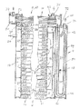
図1及び図2は、本発明による高圧気体冷却装置の第1の実施態様及び第2の実施態様の断面図である。
【0027】
気体冷却器(2)と低圧側(48)のマニホルド(4)とは、図1と図2に示す異なる例において同一である。図1では、内部熱交換器(6)は、気体冷却器(2)と、自動車内の通常の取り付け位置、つまり下端側で一体形成されており、図2では、上端側で一体形成されている。
【0028】
図2では、気相の冷媒は、低圧側(48)のマニホルド(4)から、送りチューブ(54)を通って流出する。なお、図1では、送りチューブ(54)を設ける必要はない。上述したユニットは、アルミニウム、アルミニウム合金、または、これらの混合材料で形成されている。
【0029】
図1及び図2の実施例において、気体冷却器(2)は、互いに平行な偏平チューブを有する第1熱交換チューブ(8)の列を備えている。放熱板(10)の間には、第1熱交換チューブ(8)がろう付けされている。また、内部熱交換器(6)に隣接する放熱板(10a)は、第1熱交換チューブ(8a)にろう付けされている。内部熱交換器(6)から離れている放熱板(10)は、閉じ板(12)にろう付けされている。
【0030】
以下に詳述するように、内部熱交換器(6)は、互いに直接ろう付けされた、異なる長さのチューブで構成された2つの重合部を有する第2熱交換チューブ(14)からなっている。第2熱交換チューブ(14)も、偏平チューブである。2つの隣接する偏平チューブ、つまり、内部熱交換器(6)の第2熱交換チューブ(14)と、気体冷却器(2)の第1熱交換チューブ(8a)は、放熱板(10a)にろう付けされている。
【0031】
第1熱交換チューブ(8)及び第2熱交換チューブ(14)は、同様の偏平チューブである。
【0032】
気体冷却器(2)の第1熱交換チューブ(8)の両端は、分配用のチューブ、つまり、複数のチャンバ(18)(20)に分割されたマニホルドチューブ(16)に開口している。マニホルドチューブ(16)のチャンバ(18)は、チャンバ(20)からずらされている。そのため、図示する矢印に沿って、気体冷却器(2)の長手方向に流れる冷媒は、第1熱交換チューブ(8)を介して、チャンバ(18)とチャンバ(20)との間で、横方向、つまり、自動車内の通常の取り付け位置に設けられた気体冷却器(2)の上方を流れる。
【0033】
冷媒は、「最上部」、つまり、図1では、内部熱交換器(6)から離れている一端側の流入側口金(22)、図2では、内部熱交換器(6)に近接して、かつ、その外周面に取り付けられた流入側口金(24)から供給される。これらの実施例においては、低圧側(48)のマニホルド(4)は、気体冷却器(2)に沿って延びている。
【0034】
図5に示すように、マニホルド(4)は、ダイカストやプレス成形により、中間路(26)及び隣接するマニホルドチューブ(16)と一体成形されている。
【0035】
低圧側(48)のマニホルド保持部には、液相(30)と気相(32)との境界を示す目盛り線(28)が付されている。
【0036】
図1及び図2の実施例において、高圧気体冷却装置の(例えば、図4に示す)エバポレータ(34)から流出した少量の液相を含む気相の冷媒は、低圧側(48)にあるマニホルド(4)の上部カバー(38)に取り付けられた流入側口金(36)を介して、矢印(40)に沿ってマニホルド(4)に流入する。なお、冷媒は、湾曲部(42)を通って、低圧側(48)にあるマニホルド(4)の内周面下方に向かって、らせん状に流れる。
【0037】
図1に示す実施例では、液相から気化した冷媒は、上部孔(44)を介して、中間路(26)に流れる。また、低圧側(48)のマニホルド(4)は、下部孔(46)を介して、中間路(26)と連通している
【0038】
下部孔(46)は、少量の液相の冷媒が、マニホルド(4)の底部に蓄積する潤滑油を、中間路(26)に運ぶことができるような大きさとなっている。中間路(26)の下端は、内部熱交換器(6)のマニホルド(50)の低圧側(48)と連通している(この点に関しては、図1及び図2の実施例において同じである)。
【0039】
低圧側(48)のマニホルド(4)によって、液相の冷媒は分離収集され、内部熱交換器(6)の低圧側(48)に、気相の冷媒だけが供給される。
【0040】
図1に示す第1の実施例では、気相の冷媒は、液相(30)の目盛り線(28)よりも上方にある上部孔(44)を経て、中間路(26)の「下方」に向かって流れる。
【0041】
下部孔(46)には、冷媒が流れ、低圧側(48)にあるマニホルド(4)の底部にある潤滑油と混合した液相が過度に蓄積されることを防止するためにのみ用いられる。それにより、液相の冷媒は、常に下部孔(46)を通過して、中間路(26)に戻される。
【0042】
冷媒の液相が流れることは、本質的に好ましいことではなく、通常は、潤滑油を中間路(26)の下方に流すための運搬手段としてのみ用いられる。また、低圧側(48)のマニホルド(4)にある気相(32)と液相(30)との境界である目盛り線(28)は、冷媒の充填や、自動車の運転状況により変化する。
【0043】
図2に示す第2の実施例は、第1の実施例と機能的には同じであるが、内部熱交換器(6)を気体冷却器(2)の上部に設けてある点で、異なる構造となっている。
【0044】
中間路(26)は、マニホルドチューブ(16)の下方にあるチャンバ(18)から「上方」に向かって、高圧の冷媒を戻す通路となっている。冷媒は、第1熱交換チューブ(8a)(8b)を介して、流入側口金(24)が取り付けられたチャンバ(20)の上方にあるチャンバ(20a)へ流れる。その後、冷媒は、チャンバ(20a)から、内部熱交換器(6)のマニホルド(50)の高圧側(52)に流れる。
【0045】
図1の実施例と比べると、図2の実施例では、送りチューブ(54)は、低圧側(48)のマニホルド(4)内に設けられ、かつ、マニホルド(4)の液相(30)の底部(56)付近まで延びている。また、湾曲部(42)の開口よりも上方に位置し、低圧側(48)のマニホルド(4)内にある送りチューブ(54)の一端には、液相から気化された冷媒が供給される。
【0046】
送りチューブ(54)に流れた気相の冷媒は、内部熱交換器(6)の低圧側(48)を流れる(図1では、上部孔(44)及び中間路(26)を介して流れる)。
【0047】
送りチューブ(54)のU型の底部(56)には、放出孔(58)が形成されている。低圧側(48)にあるマニホルド(4)の底部における圧力勾配により、潤滑油と混合した液相の冷媒は、送りチューブ(54)内の気相の冷媒とともに流れる。
【0048】
図7及び図8により、さらに詳しくわかるように、冷媒を反対方向に流す第2熱交換チューブ(14)の列を有する、図1及び図2の内部熱交換器(6)は、次のような基本的構造を有している。
【0049】
気体冷却器(2)及び内部熱交換器(6)において、外形及び内部断面を同一とした偏平チューブが、気体冷却器(2)の第1熱交換チューブ(8)、及び内部熱交換器(6)の第2熱交換チューブ(14)として用いられている。
【0050】
図7では、気体冷却器(2)の長手方向に延びる第1熱交換チューブ(8)の列、及び内部熱交換器(6)の列の第2熱交換チューブ(14)の第1重合部(60)は、垂直方向に重合されており、第1熱交換チューブ(8)及び第2熱交換チューブ(14)の縁は、垂直方向に見ると同一面となっている。
【0051】
内部熱交換器(6)において、第1重合部(60)と同一に構成されている内部熱交換チューブ(14)の第2重合部(62)は、第1重合部(60)の側方に近接して設けられている。2つの重合部(60)(62)間の中央に設けられている冷媒のための中央孔(64)は、常に開いている。
【0052】
図7からわかるように、中央孔(64)を含む第1重合部(60)の一側面から、第2重合部(62)の一側面までの幅は、内部熱交換器(6)のマニホルド(50)の内径とほぼ同じである。中央孔(64)までの高さは、気体冷却器(2)の第1熱交換チューブ(8)の列の高さの2倍以上となっている。
【0053】
内部熱交換器(6)のマニホルド(50)の外径は、低圧側(48)にある環状のマニホルド(4)の端面(94)の外径とほぼ同じであるので、自動車内における取り付け位置が同じ高さとなる。取り付け位置を同じ高さとすることにより、2つの重合部(60)(62)を有する第2熱交換チューブ(14)の高さを、同等に機能する単一の重合部の高さの半分とすることができる。
【0054】
長い偏平チューブ(66)と短い偏平チューブ(68)とが交互に重合されて、重合部(60)(62)が構成されており、中央孔(64)は、通路となっている。長い偏平チューブ(66)は、マニホルド(50)を介して、離れている低圧側(48)と連通しており、短い偏平チューブ(68)は、マニホルド(50)の高圧側(52)と連通している。
【0055】
偏平チューブ(66)(68)は、口金(70)を介して、マニホルドチューブ(16)の隣接するチャンバ(20)と連通している。
【0056】
低圧側(48)は、口金(72)を介して、図1では中間路(26)と、図2では送りチューブ(54)と連通している。この場合、2つの口金(70)(72)は、内部熱交換器(6)の入力側にそれぞれ設けられている。
【0057】
高圧気体冷却装置を示す図4から詳しくわかるように、出力側では、内部熱交換器(6)の低圧側(48)が、流出側口金(74)を介して気体冷却器(2)に、また、流出側口金(76)を経て、高圧側(52)に接続されている。
【0058】
図4は、図1の気体冷却器(2)を一体化した高圧気体冷却装置のブロック図であり、冷媒の流れる方向を示してある。冷媒は、コンプレッサ(78)から、高圧流路(82)を経て、気体冷却器(2)の流入側口金(24)に流れるとともに、内部熱交換器(6)から、高圧流路(82)の流出側口金(76)及び高圧流路(84)を経て、スロットル装置(80)へ流れる。
【0059】
高圧の冷媒を低圧とするスロットル装置(80)は、低圧流路(86)を経て、エバポレータ(34)に接続されている。エバポレータ(34)は、液相の冷媒の少なくとも一部を気化し、低圧流路(88)を介して、低圧側にあるマニホルド(4)の上部カバー(38)に取り付けられた流入側口金(36)へ送る。
【0060】
気相の冷媒は、低圧側にあるマニホルド(4)及び内部熱交換器(6)を通過した後、内部熱交換器(6)の流出側口金(74)から流出し、閉回路になっているので、低圧流路(90)を介して、コンプレッサ(78)の入力側に流入する。
【0061】
マニホルド(50)内の低圧側(48)及び高圧側(52)は、冷媒が漏れないように、長い第2熱交換チューブ(14)の基部となっている分離壁(92)により分離されている。
【0062】
図8からわかるように、メッキ処理された金属板の分離壁(92)が設けられたマニホルド(50)のハウジング(98)の一方の側面は、一体的な端壁(96)となっている。端壁(96)には、内部熱交換器(6)のマニホルド(50)の高圧側(52)に接続される口金(70)が一体的に設けられている。
【0063】
マニホルド(50)のハウジング(98)の他方の側面には、リム(102)を有する分離カバー(100)がろう付けされている。分離カバー(100)には、冷媒を、低圧側(48)の偏平チューブ(66)に、または、低圧流路(90)に流す、マニホルド(50)の低圧側(48)で用いられる流出側口金(74)が設けられている。
【0064】
ハウジング(98)への分離カバー(100)のろう付け位置を調節可能とするスタッド(104)が、分離壁(92)に設けられている。また、スタッド(104)により嵌合され、ハウジング(98)の位置を固定するスタッド孔(106)が、分離カバー(100)に形成されている。
【0065】
図7及び図8では、第2熱交換チューブ(14)は、第1熱交換チューブ(8)と平行に設けられているが、図6では、チューブは直交して設けられている。
【0066】
図6の実施例では、長い偏平チューブ(66)が貫通するマニホルド(50)の高圧側(52)において、高圧の冷媒は、短い偏平チューブ(68)内を流れる。偏平チューブ(68)(66)は、図8に示す実施例と同様に、交互に重合されているのが好ましい。
【0067】
他の構成、例えば、1本の偏平チューブ(66)を、2本の偏平チューブ(68)と組み合わせてもよい。
【0068】
図6のように構成すると、中央孔(64)が不要となる。第2熱交換チューブ(14)の重合部は、周囲空気が流入する方向(第1熱交換チューブ(8)の長手方向)から見て、気体冷却器(2)と同じ高さとなる。
【0069】
図6に示すマニホルド(50)の構造は、図8に示すものと同様である。
【0070】
唯一の相違点は、図6の分離カバー(100)は、ハウジング(98)にろう付けするためのリム(102)を有していないことである。
【0071】
高圧側(52)の口金(70)を用いて、マニホルド(50)をマニホルドチューブ(16)にろう付けする前に、ろう付けリング(108)が、これら2つの部材の間に挿入されている。
【0072】
定圧構造とするために、ろう付け品質には関係なく、図5に示す3つの部材、つまりマニホルドチューブ(16)、中間路(26)、及び低圧側(48)のマニホルド(4)を、押し出しにより一体成形するのがよい。
【0073】
第1熱交換チューブ(8)を収容するチューブホルダスロット(110)が、押し出し成形に続いて形成される。チューブホルダスロット(110)には、第1熱交換チューブ(8)を良好にろう付けできるようにするフランジ(114)を備える取付板(112)を介して、直接的または間接的に、第1熱交換チューブ(8)の端が取り付けられる。
【0074】
取付板(112)は、押し出し成形された第1熱交換チューブ(8)を、押し出し成形されたマニホルドチューブ(16)にろう付けするのに必要なメッキ部として用いられる。メッキは、取付板(112)の両面にコーティングされている。
【0075】
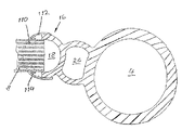
図3a及び図3bは、図1の熱交換器をエンジンクーラーに取り付けた時の、低圧側にあるマニホルドの軸線方向と平行に見た図である。取り付け位置では、低圧側(48)のマニホルド(4)は、マニホルドチューブ(16)とともに、垂直に設けられている。
【0076】
図3a及び図3bでは、内部熱交換器(6)の機能を詳しく表すために、内部熱交換器(6)を断面で示してある。また、熱交換チューブからなる熱交換部(118)と、冷媒を熱交換部(118)のそれぞれに供給する、またはそこから放出するマニホルド部(120)とを有するエンジンクーラー(116)を詳細に示してある。
【0077】
図3a及び図3bに示す熱交換器(6)の諸要素は、図1及び図8のものと同じである。
【0078】
気体冷却器(2)のマニホルドチューブ(16)は、空気方向Aに関して、中間路(26)を介して、熱交換部(118)にできるだけ近接して設けられている。これにより、エンジンクーラー(116)と気体冷却器(2)とからなるユニットの全体的な空気方向Aの高さは、可能な限り小となっている。
【0079】
空気方向Aと直交して設けられた、第1重合部(60)及び第2重合部(62)を有する内部熱交換器(6)の幅は、内部熱交換器(6)及び気体冷却器(2)の高さの2倍となっている。
【0080】
図3a及び図3bに示すように、気体冷却器を全体的に高くし、第2熱交換チューブ(14)の付加的なチューブ、つまり、第2重合部(62)を設けることができる。
【0081】
図3aにおいて、気体冷却器(2)の第1熱交換チューブ(8)と同じ垂直面に設けられた第2熱交換チューブ(14)の第1重合部(60)は、空気方向Aに関して、適正許容差内で熱交換部(118)の前方に直接的に設けられている。一方、第2熱交換チューブ(14)の第2重合部(62)は、エンジンクーラー(116)の熱交換部(118)の下方に設けられている。
【0082】
図3aにおいて、内部熱交換器(6)のマニホルド(50)は、同様に、熱交換部(118)の下方、またはエンジンクーラー(116)のマニホルド部(120)の下方に設けられている。
【0083】
図3aの実施例は、空気方向Aに関して、第2重合部(62)の幅が、内部熱交換器(6)の幅と同じでない場合や、マニホルド部(120)の長手方向から見て、熱交換部(118)よりも幅広で、内部熱交換器(6)と同じ幅の自動車用金具が、空気流を妨害する場合に好ましく、また、性能を劣化させることがない。
【0084】
図3bの実施例は、内部熱交換器(6)内に設けられた内部熱交換チューブ(14)の第2重合部(62)に対して、空気が良好に通過し、かつ、空気方向Aに十分な空間がある場合に好ましい。
【0085】
気体冷却器(2)の第1熱交換チューブ(8)の間隔が、熱交換部(118)の熱交換チューブの間隔と同じである場合には、放熱板で形成された連結壁であるリブ(10c)を用いて、2つの偏平チューブを接続することができる。
【0086】
図1及び図2に示した本発明の内部熱交換器(6)、及びエンジンクーラー(116)の熱交換部(118)を、単一処理でろう付けできるため、ろう付け時間を短縮でき、かつ、内部熱交換器(6)をエンジンクーラー(116)に固着する必要がなくなる。
【0087】
空気方向Aに対して、横方向にルーバーカットされたリブ(10c)によって、熱交換部(118)から気体冷却器(2)の偏平チューブへの望ましくない熱流が大きく制限され、エンジン冷却装置と高圧気体冷却装置と異なる温度で動作することができるようになる。
【0088】
気体冷却器(2)、低圧側のマニホルド(4)、及び内部熱交換器(6)を備える高圧気体冷却装置において、気体冷却器(2)を、内部熱交換器(6)及び低圧側のマニホルド(4)と密接して接続することができる。
【0089】
なお、気体冷却器(2)は、低圧側のマニホルド(4)(図5)と内部熱交換器(6)(図6〜図8)とを連結する連結壁を有している。
【図面の簡単な説明】
【図1】 内部熱交換器及び低圧側のマニホルドを、単一ユニットとした高圧気体冷却装置の第1の実施例の縦断面図である。
【図2】 内部熱交換器及び低圧側のマニホルドを、単一ユニットとした高圧気体冷却装置の第2の実施例の縦断面図である。
【図3】 図3及び図3bは、図1の熱交換器をエンジンクーラーに取り付けた時の、低圧側にあるマニホルドの底面図である。
【図4】 本発明による高圧気体冷却装置の回路ブロック図である。
【図5】 高圧気体冷却装置のマニホルド、中間路、及びマニホルドチューブの拡大断面図である。
【図6】 気体冷却器のマニホルドチューブが内部熱交換器のマニホルドに接続され、第2熱交換チューブが第1熱交換チューブと直交している時の拡大断面図である。
【図7】 一体成形されたマニホルド、中間路、及びマニホルドチューブの拡大断面図である。
【図8】 内部熱交換器のハウジングの一方の側面にカバーが取り付けられる時の斜視図である。
【符号の説明】
2 気体冷却器
4 マニホルド
6 内部熱交換器
8、8a 第1熱交換チューブ
10、10a 放熱板
10c リブ
12 閉じプレート
14 第2熱交換チューブ
16 マニホルドチューブ
18、20 チャンバ
22、24、36 流入側口金
26 中間路
28 目盛り線
30 液相
32 気相
34 エバポレータ
38 上部カバー
40 矢印
42 湾曲部
44 上部孔
46 下部孔
48 低圧側
50 マニホルド
52 高圧側
54 送りチューブ
56 底部
58 放出孔
60 第1重合部
62 第2重合部
64 中央孔
66、68 偏平チューブ
70、72 口金
74、76 流出側口金
78 コンプレッサ
80 スロットル装置
82、84 高圧流路
86、88、90 低圧流路
92 分離壁
94 端面
96 端壁
98 ハウジング
100 分離カバー
102 リム
104 スタッド
106 スタッド孔
108 ろう付けリング
110 チューブホルダスロット
112 取付板
114 フランジ
116 エンジンクーラー
118 熱交換部
120 マニホルド部[0001]
BACKGROUND OF THE INVENTION
The present invention relates to a high-pressure gas cooling device for an automotive air conditioner including a gas cooler, and more specifically, a supercritical CO.2CO with gas cooler2The present invention relates to a high-pressure gas cooling device (not limited to this).
[0002]
[Prior art]
The conventional technology and problems of gas coolers, such as those described above, are described in “Automobiles” patented in Germany by Jurgen Wertenbach, Jurgen Maue, and Wolfgang Volz. CO in air conditioning equipment2It is described in detail in the specification of “cooling device”.
[0003]
FIG. 2 of the specification describes a so-called RACE project. The present invention is a further improvement of the results of the RACE project.
[0004]
The features of the present invention related to the preamble in claims 1 to 3 are shown in FIG. 4 of the specification.
[0005]
That is, a problem occurs when carbon dioxide is used in place of a refrigerant of an automobile air conditioner, for example, R134a, in particular to reduce the greenhouse effect. In the RACE project described above, the circuit shown in FIG.2The maximum efficiency was obtained using.
[0006]
On the other hand, in an automotive air conditioner using a conventional refrigerant, an internal heat exchanger that performs heat exchange between a high-pressure side and a low-pressure side is provided as a new member. In the conventional gas cooler,ManifoldWere equally used on the low pressure side and the high pressure side. On the low pressure sideManifoldIt is preferable to provide the maximum efficiency in the operation mode of the present invention. Details thereof are described in the above specification.
[0007]
[Problems to be solved by the invention]
An object of the present invention is to provide a high-pressure gas cooling device that has the following requirements at least individually or in combination.
[0008]
1. The number of pressure channels required for high pressure operation should be minimized. When the number of pressure-resistant channels is reduced, the number of screws connecting the channels is also reduced. The screw connection is necessary for high pressure operation and is a risk of rupture.2Is necessary for the inflow.
2. The new component internal heat exchanger should require little or no space required for installation within the vehicle.
3. The low pressure side manifold should be used for space and cost savings.
4). In an automobile having a conventional air conditioner, the installation space can be reduced by replacing predetermined members.2The high-pressure gas cooling device should be configured so that it can be used for an air conditioner having the necessary members for operation.
[0009]
[Means for Solving the Problems]
In the first aspect of the present invention, a high-pressure gas cooling device for an automotive air conditioner, comprising a gas cooler provided in the refrigerant flow direction, and an internal heat exchanger that performs heat exchange between the high-pressure side and the low-pressure side. The gas cooler and the internal heat exchanger are configured as a single unit.
[0010]
In the second aspect of the present invention, heat exchange is performed between the high-pressure side and the low-pressure side, and is provided along the flow direction of the refrigerant that communicates with the input side of the compressor via the low-pressure side of the internal heat exchanger. In a high-pressure gas cooling device for an automotive air conditioner provided with an internal heat exchanger, a gas cooler, an internal heat exchanger, and a low-pressure sideManifoldAre configured as a single unit.
[0011]
In the third aspect of the present invention, heat is exchanged between the high-pressure side and the low-pressure side, the internal heat exchanger provided in the refrigerant flow direction, and the low-pressure side of the internal heat exchanger, the input side of the compressor On the low pressure side in communication withManifoldA high pressure gas cooling device for an automotive air conditioner comprising: a gas cooler and a low pressure sideManifoldIs composed of a single unit.
[0012]
The dependent claims, for example claims 2 to 4, relate to the basic structure of the high-pressure gas cooling device according to the invention, which is preferred in terms of manufacturing, miniaturization and the use of similar components.~ 6Relates to further unitization of members.
[0013]
The “first” heat exchange tube of the high-pressure gas cooling device is basically rib-shaped,7As described in, the unit may be miniaturized using a non-ribbed heat exchange tube.
[0014]
For example, in a normal automobile air conditioner,8It is preferable to use a heat exchanger having a flat heat exchange tube.
[0015]
The length of the flat tube depends on whether it is connected to the high pressure side or the low pressure side, and is selectively connected to different chambers on the low pressure side and the high pressure side.
[0016]
In another embodiment, the refrigerant flows through a short flat tube.
[0017]
Claim13-15Of the internal heat exchangerManifoldIt is related with the preferable form.
[0018]
Claim2-23IsDirectly or indirectlyDependent on claim 1, the content of claim 1 being claimed2-23Included.
[0019]
Claim16According to the low-pressure sideManifoldIs provided along the “first” heat exchange tube of the gas cooler, ie, transversely to the heat exchange tube, while the internal heat exchanger is provided at one end of the gas cooler, 2 "is preferably aligned with the heat exchange tube.
[0020]
Claim17As shown, the intermediate path is connected to the gas coolerManifoldThe internal heat exchanger is provided above or below the gas cooler, so that the refrigerant flows through the intermediate path having the minimum required diameter. Therefore, CO2The external flow path for the refrigerant can be minimized.
[0021]
Claim18 and 19Claims17Subordinate to
[0022]
Claim19Is related to the prevention of accumulation of lubricating oil in the compressor by easy means and the selective use of conventional feed flow paths. (RACE dated 17 July 1997 by Volkswagen AG's H. Rohe, B. Adiprasito, and Dr U. Brennenstuhl) See FIG. 1 in “Project-Final Technical Task Report for
[0023]
Claim20 and 21Are related to the two basic principles described above in order to complete the present invention.
[0024]
Claim22 and 23Relates to a preferred assembly unit incorporating an engine cooler according to the invention.
[0025]
Embodiment
Next, the present invention will be described with reference to the drawings. In the drawings, the same members are denoted by the same reference numerals.
[0026]
1 and 2 are sectional views of a first embodiment and a second embodiment of a high-pressure gas cooling device according to the present invention.
[0027]
The gas cooler (2) and the low pressure side (48)Manifold(4) is the same in the different examples shown in FIG. 1 and FIG. In FIG. 1, the internal heat exchanger (6) is integrally formed with the gas cooler (2) at a normal mounting position in the automobile, that is, at the lower end side, and in FIG. 2, it is integrally formed at the upper end side. Yes.
[0028]
In FIG. 2, the gas phase refrigerant is on the low pressure side (48).ManifoldFrom (4), it flows out through the feed tube (54). In addition, in FIG. 1, it is not necessary to provide a feed tube (54). The above-described unit is formed of aluminum, an aluminum alloy, or a mixed material thereof.
[0029]
In the embodiment of FIGS. 1 and 2, the gas cooler (2) comprises a row of first heat exchange tubes (8) having flat tubes parallel to each other. A first heat exchange tube (8) is brazed between the heat sinks (10). Moreover, the heat sink (10a) adjacent to the internal heat exchanger (6) is brazed to the first heat exchange tube (8a). A heat sink (10) that is remote from the internal heat exchanger (6) is brazed to the closing plate (12).
[0030]
As will be described in detail below, the internal heat exchanger (6) consists of a second heat exchange tube (14) having two overlapping sections composed of tubes of different lengths brazed directly to each other. Yes. The second heat exchange tube (14) is also a flat tube. Two adjacent flat tubes, namely, the second heat exchange tube (14) of the internal heat exchanger (6) and the first heat exchange tube (8a) of the gas cooler (2) are connected to the heat radiating plate (10a). It is brazed.
[0031]
The first heat exchange tube (8) and the second heat exchange tube (14) are similar flat tubes.
[0032]
Both ends of the first heat exchange tube (8) of the gas cooler (2) are divided into distribution tubes, that is, a plurality of chambers (18) and (20).ManifoldIt opens to the tube (16).ManifoldThe chamber (18) of the tube (16) is offset from the chamber (20). For this reason, the refrigerant flowing in the longitudinal direction of the gas cooler (2) along the arrow shown in the drawing passes between the chamber (18) and the chamber (20) via the first heat exchange tube (8). It flows in the direction, that is, above the gas cooler (2) provided at the normal mounting position in the automobile.
[0033]
The refrigerant is close to the “top”, that is, in FIG. 1, close to the inlet base (22) on one end side away from the internal heat exchanger (6) and in FIG. 2 to the internal heat exchanger (6). And it is supplied from the inflow side nozzle | cap | die (24) attached to the outer peripheral surface. In these embodiments, the low pressure side (48)Manifold(4) extends along the gas cooler (2).
[0034]
As shown in FIG.Manifold(4) is adjacent to the intermediate path (26) by die casting or press molding.ManifoldIt is integrally formed with the tube (16).
[0035]
Low pressure side (48)ManifoldA scale line (28) indicating a boundary between the liquid phase (30) and the gas phase (32) is attached to the holding portion.
[0036]
In the embodiment of FIGS. 1 and 2, the gaseous refrigerant containing a small amount of liquid phase that has flowed out of the evaporator (34) of the high pressure gas cooling device (eg shown in FIG. 4) is on the low pressure side (48).ManifoldAlong the arrow (40) through the inflow side cap (36) attached to the upper cover (38) of (4)ManifoldFlows into (4). Note that the refrigerant is on the low pressure side (48) through the curved portion (42).ManifoldIt flows spirally toward the lower part of the inner peripheral surface of (4).
[0037]
In the embodiment shown in FIG. 1, the refrigerant vaporized from the liquid phase flows to the intermediate path (26) through the upper hole (44). Also, the low pressure side (48)Manifold(4) communicates with the intermediate path (26) through the lower hole (46).
[0038]
In the lower hole (46), a small amount of liquid-phase refrigerant isManifoldThe lubricating oil accumulated at the bottom of (4) is large enough to be transported to the intermediate path (26). The lower end of the intermediate path (26) is connected to the internal heat exchanger (6).ManifoldIt communicates with the low pressure side (48) of (50) (this is the same in the embodiment of FIGS. 1 and 2).
[0039]
Low pressure side (48)ManifoldAccording to (4), the liquid phase refrigerant is separated and collected, and only the gas phase refrigerant is supplied to the low pressure side (48) of the internal heat exchanger (6).
[0040]
In the first embodiment shown in FIG. 1, the gas-phase refrigerant passes through the upper hole (44) above the graduation line (28) of the liquid phase (30), and "down" the intermediate channel (26). It flows toward.
[0041]
The refrigerant flows through the lower hole (46) and is on the low pressure side (48).ManifoldIt is used only to prevent excessive accumulation of the liquid phase mixed with the lubricating oil at the bottom of (4). Thereby, the liquid-phase refrigerant always passes through the lower hole (46) and is returned to the intermediate path (26).
[0042]
The flow of the liquid phase of the refrigerant is not essentially desirable and is usually only used as a transport means for flowing the lubricating oil down the intermediate passage (26). Also, the low pressure side (48)ManifoldThe scale line (28) which is the boundary between the gas phase (32) and the liquid phase (30) in (4) varies depending on the charging of the refrigerant and the driving situation of the automobile.
[0043]
The second embodiment shown in FIG. 2 is functionally the same as the first embodiment, but differs in that an internal heat exchanger (6) is provided above the gas cooler (2). It has a structure.
[0044]
The intermediate path (26)ManifoldIt is a passage for returning the high-pressure refrigerant from the chamber (18) below the tube (16) to the “upward” direction. The refrigerant flows through the first heat exchange tubes (8a) and (8b) to the chamber (20a) above the chamber (20) to which the inflow side cap (24) is attached. Thereafter, the refrigerant flows from the chamber (20a) to the internal heat exchanger (6).ManifoldIt flows to the high pressure side (52) of (50).
[0045]
Compared to the embodiment of FIG. 1, in the embodiment of FIG. 2, the feed tube (54) is on the low pressure side (48).Manifold(4) provided within, andManifoldIt extends to the vicinity of the bottom (56) of the liquid phase (30) of (4). Moreover, it is located above the opening of the curved portion (42), and the low pressure side (48)Manifold(4) The refrigerant vaporized from the liquid phase is supplied to one end of the feed tube (54) inside.
[0046]
The gas-phase refrigerant that has flowed into the feed tube (54) flows through the low-pressure side (48) of the internal heat exchanger (6) (in FIG. 1, it flows through the upper hole (44) and the intermediate passage (26)). .
[0047]
A discharge hole (58) is formed in the U-shaped bottom (56) of the feed tube (54). On the low pressure side (48)ManifoldDue to the pressure gradient at the bottom of (4), the liquid phase refrigerant mixed with the lubricating oil flows together with the gas phase refrigerant in the feed tube (54).
[0048]
As can be seen in more detail in FIGS. 7 and 8, the internal heat exchanger (6) of FIGS. 1 and 2 having a row of second heat exchange tubes (14) for flowing the refrigerant in the opposite direction is as follows. It has a basic structure.
[0049]
In the gas cooler (2) and the internal heat exchanger (6), the flat tubes having the same outer shape and internal cross section are the first heat exchange tube (8) of the gas cooler (2) and the internal heat exchanger ( 6) as the second heat exchange tube (14).
[0050]
In FIG. 7, the 1st superposition | polymerization part of the row | line | column of the 1st heat exchange tube (8) extended in the longitudinal direction of a gas cooler (2), and the 2nd heat exchange tube (14) of the row | line | column of an internal heat exchanger (6). (60) is polymerized in the vertical direction, and the edges of the first heat exchange tube (8) and the second heat exchange tube (14) are flush with each other when viewed in the vertical direction.
[0051]
In the internal heat exchanger (6), the second superposition part (62) of the internal heat exchange tube (14) configured identically to the first superposition part (60) is located on the side of the first superposition part (60). It is provided close to. The central hole (64) for the refrigerant provided in the center between the two overlapping portions (60) (62) is always open.
[0052]
As can be seen from FIG. 7, the width from one side surface of the first overlapping portion (60) including the central hole (64) to one side surface of the second overlapping portion (62) is that of the internal heat exchanger (6).ManifoldIt is almost the same as the inner diameter of (50). The height to the center hole (64) is more than twice the height of the row of the first heat exchange tubes (8) of the gas cooler (2).
[0053]
Of the internal heat exchanger (6)ManifoldThe outer diameter of (50) is an annular shape on the low pressure side (48)ManifoldSince it is almost the same as the outer diameter of the end face (94) of (4), the mounting position in the automobile is the same height. By making the mounting position the same height, the height of the second heat exchange tube (14) having two overlapping portions (60) (62) is set to be half the height of a single overlapping portion that functions equally. can do.
[0054]
The long flat tube (66) and the short flat tube (68) are alternately superposed to form a superposed portion (60) (62), and the central hole (64) is a passage. The long flat tube (66)Manifold(50) communicates with the remote low pressure side (48), and the short flat tube (68)ManifoldIt communicates with the high pressure side (52) of (50).
[0055]
The flat tubes (66) (68) are connected via the base (70).ManifoldIt is in communication with the adjacent chamber (20) of the tube (16).
[0056]
The low pressure side (48) communicates with the intermediate path (26) in FIG. 1 and the feed tube (54) in FIG. 2 via the base (72). In this case, the two caps (70) (72) are respectively provided on the input side of the internal heat exchanger (6).
[0057]
As can be seen in detail from FIG. 4 showing the high pressure gas cooling device, on the output side, the low pressure side (48) of the internal heat exchanger (6) is connected to the gas cooler (2) via the outflow side cap (74). Moreover, it connects with the high voltage | pressure side (52) through the outflow side nozzle | cap | die (76).
[0058]
FIG. 4 is a block diagram of a high-pressure gas cooling device in which the gas cooler (2) of FIG. 1 is integrated, and shows the direction in which the refrigerant flows. The refrigerant flows from the compressor (78) through the high-pressure channel (82) to the inflow side cap (24) of the gas cooler (2), and from the internal heat exchanger (6) to the high-pressure channel (82). Flows into the throttle device (80) through the outflow side cap (76) and the high-pressure channel (84).
[0059]
The throttle device (80) for reducing the high-pressure refrigerant to a low pressure is connected to the evaporator (34) via the low-pressure channel (86). The evaporator (34) vaporizes at least part of the liquid refrigerant and is on the low pressure side via the low pressure channel (88).ManifoldIt is sent to the inflow side cap (36) attached to the upper cover (38) of (4).
[0060]
Gas phase refrigerant is on the low pressure sideManifoldAfter passing through (4) and the internal heat exchanger (6), it flows out from the outflow side cap (74) of the internal heat exchanger (6) and is in a closed circuit. And flows into the input side of the compressor (78).
[0061]
ManifoldThe low pressure side (48) and the high pressure side (52) in (50) are separated by a separation wall (92) which is the base of the long second heat exchange tube (14) so that the refrigerant does not leak. .
[0062]
As can be seen from FIG. 8, a separation wall (92) of the plated metal plate was provided.ManifoldOne side of the housing (98) of (50) is an integral end wall (96). The end wall (96) has an internal heat exchanger (6)ManifoldA base (70) connected to the high pressure side (52) of (50) is integrally provided.
[0063]
ManifoldA separation cover (100) having a rim (102) is brazed to the other side of the housing (98) of (50). In the separation cover (100), the refrigerant flows through the flat tube (66) on the low pressure side (48) or the low pressure flow path (90).ManifoldAn outflow side cap (74) used on the low pressure side (48) of (50) is provided.
[0064]
A stud (104) is provided on the separation wall (92) that allows the brazing position of the separation cover (100) to the housing (98) to be adjusted. A stud hole (106) that is fitted by the stud (104) and fixes the position of the housing (98) is formed in the separation cover (100).
[0065]
7 and 8, the second heat exchange tube (14) is provided in parallel with the first heat exchange tube (8), but in FIG. 6, the tubes are provided orthogonally.
[0066]
In the embodiment of FIG. 6, a long flat tube (66) penetrates.ManifoldOn the high pressure side (52) of (50), the high pressure refrigerant flows in a short flat tube (68). The flat tubes (68) (66) are preferably polymerized alternately as in the embodiment shown in FIG.
[0067]
Other configurations, for example, one flat tube (66) may be combined with two flat tubes (68).
[0068]
When configured as shown in FIG. 6, the central hole (64) becomes unnecessary. The overlapping portion of the second heat exchange tube (14) has the same height as the gas cooler (2) when viewed from the direction in which ambient air flows (the longitudinal direction of the first heat exchange tube (8)).
[0069]
As shown in FIG.ManifoldThe structure (50) is the same as that shown in FIG.
[0070]
The only difference is that the separation cover (100) of FIG. 6 does not have a rim (102) for brazing to the housing (98).
[0071]
Using the base (70) on the high pressure side (52),ManifoldPrior to brazing (50) to the manifold tube (16), a brazing ring (108) is inserted between the two members.
[0072]
Because of the constant pressure structure, regardless of the brazing quality, the three members shown in FIG. 5, namely the manifold tube (16), the intermediate channel (26), and the low pressure side (48)Manifold(4) may be integrally formed by extrusion.
[0073]
A tube holder slot (110) that houses the first heat exchange tube (8) is formed following extrusion. The tube holder slot (110) is directly or indirectly connected to the first through an attachment plate (112) with a flange (114) that allows the first heat exchange tube (8) to be brazed well. The end of the heat exchange tube (8) is attached.
[0074]
The mounting plate (112) was formed by extruding the extruded first heat exchange tube (8).ManifoldUsed as a plating part necessary for brazing the tube (16). The plating is coated on both sides of the mounting plate (112).
[0075]
3a and 3b are on the low pressure side when the heat exchanger of FIG. 1 is mounted on an engine cooler.ManifoldIt is the figure seen in parallel with the axis line direction. At the mounting position, the low pressure side (48)Manifold(4)ManifoldAlong with the tube (16), it is provided vertically.
[0076]
In FIGS. 3 a and 3 b, the internal heat exchanger (6) is shown in cross-section in order to describe in detail the function of the internal heat exchanger (6). In addition, the refrigerant is supplied to or discharged from each of the heat exchange section (118) including the heat exchange tubes and the heat exchange section (118).Manifold partThe engine cooler (116) with (120) is shown in detail.
[0077]
The elements of the heat exchanger (6) shown in FIGS. 3a and 3b are the same as those of FIGS.
[0078]
Of the gas cooler (2)ManifoldWith respect to the air direction A, the tube (16) is provided as close as possible to the heat exchange section (118) via the intermediate path (26). Thereby, the height of the whole air direction A of the unit which consists of an engine cooler (116) and a gas cooler (2) is as small as possible.
[0079]
The width of the internal heat exchanger (6) having the first superposition part (60) and the second superposition part (62) provided perpendicular to the air direction A is the same as that of the internal heat exchanger (6) and the gas cooler. It is twice the height of (2).
[0080]
As shown in FIGS. 3 a and 3 b, the gas cooler can be raised overall and an additional tube of the second heat exchange tube (14), i.e. the second superposition part (62), can be provided.
[0081]
In FIG. 3a, the first overlapping portion (60) of the second heat exchange tube (14) provided on the same vertical plane as the first heat exchange tube (8) of the gas cooler (2) It is provided directly in front of the heat exchanging part (118) within an appropriate tolerance. On the other hand, the second superposition part (62) of the second heat exchange tube (14) is provided below the heat exchange part (118) of the engine cooler (116).
[0082]
In FIG. 3a, the internal heat exchanger (6)Manifold(50) is similarly below the heat exchanger (118) or of the engine cooler (116).Manifold part(120) is provided below.
[0083]
In the embodiment of FIG. 3a, the width of the second overlapping section (62) is not the same as the width of the internal heat exchanger (6) with respect to the air direction A,ManifoldWhen viewed from the longitudinal direction of the part (120), a vehicle bracket that is wider than the heat exchange part (118) and has the same width as the internal heat exchanger (6) is preferable in the case of obstructing the air flow. Will not deteriorate.
[0084]
In the embodiment of FIG. 3b, air passes well through the second overlapping portion (62) of the internal heat exchange tube (14) provided in the internal heat exchanger (6), and the air direction A This is preferable when there is sufficient space.
[0085]
When the interval between the first heat exchange tubes (8) of the gas cooler (2) is the same as the interval between the heat exchange tubes of the heat exchange unit (118), a rib that is a connection wall formed of a radiator plate (10c) can be used to connect two flat tubes.
[0086]
Since the internal heat exchanger (6) of the present invention shown in FIGS. 1 and 2 and the heat exchanger (118) of the engine cooler (116) can be brazed in a single process, the brazing time can be shortened, In addition, it is not necessary to fix the internal heat exchanger (6) to the engine cooler (116).
[0087]
The rib (10c) cut laterally with respect to the air direction A greatly restricts undesirable heat flow from the heat exchanging portion (118) to the flat tube of the gas cooler (2). It becomes possible to operate at a temperature different from that of the high-pressure gas cooling device.
[0088]
Gas cooler (2), low pressure sideManifold(4) In the high pressure gas cooling device including the internal heat exchanger (6), the gas cooler (2) is connected to the internal heat exchanger (6) and the low pressure side.Manifold(4) can be connected closely.
[0089]
In addition, the gas cooler (2)Manifold(4) It has a connecting wall that connects (FIG. 5) and the internal heat exchanger (6) (FIGS. 6 to 8).
[Brief description of the drawings]
Fig. 1 Internal heat exchanger and low pressure sideManifoldIt is a longitudinal cross-sectional view of the 1st Example of the high-pressure gas-cooling apparatus made into a single unit.
[Fig. 2] Internal heat exchanger and low pressure sideManifoldIt is a longitudinal cross-sectional view of the 2nd Example of the high pressure gas cooling device which made this into a single unit.
3 and 3b are on the low pressure side when the heat exchanger of FIG. 1 is installed in an engine cooler.ManifoldFIG.
FIG. 4 is a circuit block diagram of a high-pressure gas cooling device according to the present invention.
[Fig.5] High pressure gas cooling systemManifoldThe middle road, andManifoldIt is an expanded sectional view of a tube.
[Fig. 6] Gas coolerManifoldThe tube is an internal heat exchangerManifoldIt is an expanded sectional view when the 2nd heat exchange tube is orthogonally crossed with the 1st heat exchange tube.
[Fig. 7] Integrally moldedManifoldThe middle road, andManifoldIt is an expanded sectional view of a tube.
FIG. 8 is a perspective view when a cover is attached to one side surface of the housing of the internal heat exchanger.
[Explanation of symbols]
2 Gas cooler
Four Manifold
6 Internal heat exchanger
8, 8a First heat exchange tube
10, 10a Heat sink
10c rib
12 Closing plate
14 Second heat exchange tube
16 Manifold tube
18, 20 chamber
22, 24, 36 Inlet cap
26 Middle Road
28 Scale lines
30 liquid phase
32 Gas phase
34 Evaporator
38 Top cover
40 arrows
42 Curved section
44 Top hole
46 Bottom hole
48 Low pressure side
50Manifold
52 High pressure side
54 Feed tube
56 Bottom
58 Release hole
60 First polymerization part
62 Second polymerization part
64 Central hole
66, 68 Flat tube
70, 72 base
74, 76 Outlet cap
78 Compressor
80 Throttle device
82, 84 High pressure flow path
86, 88, 90 Low pressure flow path
92 Separation wall
94 End face
96 end wall
98 housing
100 separation cover
102 rim
104 Stud
106 Stud hole
108 Brazing ring
110 Tube holder slot
112 Mounting plate
114 flange
116 engine cooler
118 Heat exchanger
120ManifoldPart
Claims (23)
前記冷媒回路は、冷媒の流れ方向において、
偏平な第1熱交換チューブ(8)の列を有する気体冷却器(2)と;
内部熱交換器(6)であって、高圧側(52)と低圧側(48)との熱交換を行い、低圧側を介してコンプレッサ(78)の入力側と連通している内部熱交換器(6)とを有していて;
前記内部熱交換器(6)は、互いにろう付けされ、高圧側(52)と低圧側(48)とに交互に割り当てた第2熱交換チューブ(14)の列を有すること、及び
前記内部熱交換器(6)は、冷媒を反対方向に流すように設計されていて、且つ、気体冷却器(2)と組み合わされて単一ユニットとして構成してあることを特徴とする冷媒回路を有する自動車用空調装置の臨界超過のCO 2 高圧冷媒回路の高圧気体冷却装置。 A gas cooling device for a supercritical CO 2 high-pressure refrigerant circuit of an automotive air conditioner having a refrigerant circuit ,
In the refrigerant flow direction, the refrigerant circuit,
A gas cooler (2) having a row of flat first heat exchange tubes (8);
An internal heat exchanger (6) for exchanging heat between the high pressure side (52) and the low pressure side (48) and communicating with the input side of the compressor (78) via the low pressure side Having (6);
The internal heat exchanger (6) has a row of second heat exchange tubes (14) brazed together and alternately assigned to the high pressure side (52) and the low pressure side (48); and
The internal heat exchanger (6) is designed to flow the refrigerant in the opposite direction, and is configured as a single unit in combination with the gas cooler (2). A high-pressure gas cooling device for a supercritical CO 2 high-pressure refrigerant circuit of an automotive air conditioner having
Applications Claiming Priority (2)
| Application Number | Priority Date | Filing Date | Title |
|---|---|---|---|
| DE19918617:0 | 1999-04-23 | ||
| DE19918617A DE19918617C2 (en) | 1999-04-23 | 1999-04-23 | Gas cooler for a supercritical CO¶2¶ high pressure refrigerant circuit of an automotive air conditioning system |
Publications (2)
| Publication Number | Publication Date |
|---|---|
| JP2000318432A JP2000318432A (en) | 2000-11-21 |
| JP4394802B2 true JP4394802B2 (en) | 2010-01-06 |
Family
ID=7905705
Family Applications (1)
| Application Number | Title | Priority Date | Filing Date |
|---|---|---|---|
| JP2000123063A Expired - Fee Related JP4394802B2 (en) | 1999-04-23 | 2000-04-24 | High-pressure gas cooling system for automotive air conditioners |
Country Status (5)
| Country | Link |
|---|---|
| US (1) | US6539746B1 (en) |
| EP (1) | EP1046524B2 (en) |
| JP (1) | JP4394802B2 (en) |
| DE (1) | DE19918617C2 (en) |
| ES (1) | ES2229986T5 (en) |
Families Citing this family (38)
| Publication number | Priority date | Publication date | Assignee | Title |
|---|---|---|---|---|
| FR2802291B1 (en) * | 1999-12-09 | 2002-05-31 | Valeo Climatisation | AIR CONDITIONING CIRCUIT, ESPECIALLY FOR A MOTOR VEHICLE |
| NO20005974D0 (en) * | 2000-11-24 | 2000-11-24 | Sinvent As | Cooling or heat pump system with heat release when temperature changes |
| JP3600163B2 (en) * | 2001-02-13 | 2004-12-08 | 三洋電機株式会社 | In-vehicle air conditioner |
| US20020108389A1 (en) | 2001-02-15 | 2002-08-15 | Carrier Corporation | Generator with an axial air gap design for electrically powered trailer refrigeration unit |
| JP2003097857A (en) * | 2001-07-12 | 2003-04-03 | Calsonic Kansei Corp | Air conditioning cycle |
| DE10137907A1 (en) | 2001-08-02 | 2003-02-20 | Modine Mfg Co | Air cooled heat transfer arrangement |
| DE10147521A1 (en) * | 2001-09-26 | 2003-04-10 | Behr Gmbh & Co | Heat exchangers, in particular gas coolers CO2 - air conditioners |
| DE10155001A1 (en) * | 2001-11-08 | 2003-05-22 | Behr Gmbh & Co | Refrigerant condenser |
| JP3903851B2 (en) * | 2002-06-11 | 2007-04-11 | 株式会社デンソー | Heat exchanger |
| DE102004059680B4 (en) * | 2003-12-11 | 2019-10-17 | Mahle International Gmbh | Construction arrangement for means for exchanging heat |
| DE102004018317A1 (en) * | 2004-04-13 | 2005-11-03 | Behr Gmbh & Co. Kg | Heat exchanger for motor vehicles |
| JP4400332B2 (en) * | 2004-06-18 | 2010-01-20 | 株式会社デンソー | Air conditioner for vehicles |
| DE102004033457B4 (en) * | 2004-07-05 | 2007-12-20 | Visteon Global Technologies, Inc., Dearborn | Composite of a high strength aluminum alloy |
| FR2875894B1 (en) | 2004-09-24 | 2006-12-15 | Valeo Climatisation Sa | COMBINED INTERNAL HEAT EXCHANGER AND ACCUMULATOR DEVICE FOR AIR CONDITIONING CIRCUIT |
| DE102005005187A1 (en) * | 2005-02-03 | 2006-08-10 | Behr Gmbh & Co. Kg | Condenser for an air conditioning system, in particular a motor vehicle |
| DE102005021787A1 (en) * | 2005-05-11 | 2006-11-16 | Modine Manufacturing Co., Racine | Transcritical air-conditioning refrigerant e.g. carbon-di-oxide, treating apparatus for use in e.g. automobile, has flat multi-chamber tube extruded to extend straight over length of vessel |
| JP4667134B2 (en) * | 2005-06-22 | 2011-04-06 | サンデン株式会社 | Air conditioner for vehicles |
| DE202005012048U1 (en) * | 2005-07-22 | 2006-12-07 | Liebherr-Hausgeräte Ochsenhausen GmbH | Pipe / plate liquefier for refrigerators and / or freezers |
| DE102005040607A1 (en) * | 2005-08-27 | 2007-03-15 | Behr Gmbh & Co. Kg | Arrangement for fixing a heat exchanger to another |
| FR2890726B1 (en) * | 2005-09-13 | 2007-12-14 | Valeo Systemes Thermiques | INTEGRATED ASSEMBLY FOR AIR CONDITIONING CIRCUIT OPERATING WITH SUPERCRITICAL REFRIGERANT FLUID |
| DE102005045539A1 (en) * | 2005-09-23 | 2007-03-29 | Valeo Klimasysteme Gmbh | Inner heat exchanger for a refrigerant circuit of an air conditioner |
| US20070095505A1 (en) * | 2005-10-28 | 2007-05-03 | Thomas Robinson | Starter controller coolant outlet flow kit |
| DE102006007371A1 (en) * | 2006-02-17 | 2007-08-23 | Bayerische Motoren Werke Ag | Vehicle air conditioning |
| US7621150B2 (en) * | 2007-01-05 | 2009-11-24 | Delphi Technologies, Inc. | Internal heat exchanger integrated with gas cooler |
| FR2912208B1 (en) * | 2007-02-06 | 2016-04-01 | Valeo Systemes Thermiques | DIODE EXCHANGER |
| JP2009024899A (en) * | 2007-07-17 | 2009-02-05 | Showa Denko Kk | Evaporator |
| JP2009166529A (en) * | 2008-01-11 | 2009-07-30 | Calsonic Kansei Corp | Vehicular condenser |
| KR101082349B1 (en) | 2009-05-26 | 2011-11-10 | 한국과학기술원 | Carbon Dioxide Liquefaction Equipment Using Internal Heat Exchange |
| FR2960951B1 (en) | 2010-06-07 | 2013-07-26 | Valeo Systemes Thermiques | UNITARY SYSTEM COMPRISING A CONDENSER, AN INTERNAL HEAT EXCHANGER AND BOTTLE OF A CLIMATE LOOP |
| FR2960950B1 (en) | 2010-06-07 | 2013-12-06 | Valeo Systemes Thermiques | UNITARY SYSTEM COMPRISING A CONDENSER, A BOTTLE AND AN INTERNAL HEAT EXCHANGER |
| JP5960955B2 (en) | 2010-12-03 | 2016-08-02 | 現代自動車株式会社Hyundai Motor Company | Vehicle capacitors |
| FR2974409B1 (en) * | 2011-04-21 | 2018-01-05 | Valeo Systemes Thermiques | HEAT EXCHANGER FOR A HEATING, VENTILATION AND / OR AIR CONDITIONING INSTALLATION |
| DE102011089091A1 (en) * | 2011-12-19 | 2013-06-20 | Behr Gmbh & Co. Kg | Heat exchanger |
| US9046287B2 (en) * | 2013-03-15 | 2015-06-02 | Whirlpool Corporation | Specialty cooling features using extruded evaporator |
| DE102013114081A1 (en) | 2013-12-16 | 2015-06-18 | Valeo Klimasysteme Gmbh | Vehicle air conditioning |
| DE102018215024B4 (en) | 2018-09-04 | 2021-01-07 | Audi Ag | Method for operating a refrigeration system for a vehicle and a refrigeration system |
| US20230173874A1 (en) * | 2021-12-07 | 2023-06-08 | Mahle International Gmbh | Plate ihx as mounting plate for refrigerant module |
| WO2023126075A1 (en) * | 2022-01-03 | 2023-07-06 | Huawei Technologies Co., Ltd. | Heat exchange arrangement |
Family Cites Families (15)
| Publication number | Priority date | Publication date | Assignee | Title |
|---|---|---|---|---|
| US3131553A (en) * | 1962-04-12 | 1964-05-05 | Ross Anthony John | Refrigeration system including condenser heat exchanger |
| DE3306232A1 (en) † | 1983-02-23 | 1984-08-23 | Fichtel & Sachs Ag, 8720 Schweinfurt | Modular unit consisting of condenser, collector and liquid separator for a heat pump |
| NO890076D0 (en) * | 1989-01-09 | 1989-01-09 | Sinvent As | AIR CONDITIONING. |
| US5245836A (en) * | 1989-01-09 | 1993-09-21 | Sinvent As | Method and device for high side pressure regulation in transcritical vapor compression cycle |
| US5289698A (en) † | 1992-09-14 | 1994-03-01 | General Motors Corporation | Modular nested vapor compression heat pump for automotive applications |
| FR2709344B1 (en) † | 1993-08-27 | 1995-10-13 | Valeo Thermique Moteur Sa | Condenser for motor vehicle air conditioning system. |
| DE4402927B4 (en) * | 1994-02-01 | 2008-02-14 | Behr Gmbh & Co. Kg | Condenser for an air conditioning system of a vehicle |
| JPH08136086A (en) * | 1994-11-01 | 1996-05-31 | Nippondenso Co Ltd | Refrigerant evaporator |
| DE19522884A1 (en) * | 1995-06-23 | 1997-01-02 | Inst Luft Kaeltetech Gem Gmbh | Compression refrigeration circuit operating system |
| JP3371627B2 (en) † | 1995-07-20 | 2003-01-27 | 株式会社デンソー | Heat exchange equipment for vehicles |
| DE19635454B4 (en) * | 1996-08-31 | 2010-06-17 | Behr Gmbh & Co. Kg | Collector heat exchanger assembly and air conditioning equipped therewith |
| DE19646349B4 (en) † | 1996-11-09 | 2011-08-11 | Behr GmbH & Co. KG, 70469 | Evaporator and vehicle air conditioning system equipped therewith |
| JP3508465B2 (en) * | 1997-05-09 | 2004-03-22 | 株式会社デンソー | Heat exchanger |
| US6105386A (en) * | 1997-11-06 | 2000-08-22 | Denso Corporation | Supercritical refrigerating apparatus |
| DE19830757A1 (en) † | 1998-07-09 | 2000-01-13 | Behr Gmbh & Co | Air conditioning system especially for a motor vehicle |
-
1999
- 1999-04-23 DE DE19918617A patent/DE19918617C2/en not_active Expired - Fee Related
-
2000
- 2000-04-20 US US09/552,966 patent/US6539746B1/en not_active Expired - Lifetime
- 2000-04-21 ES ES00108690T patent/ES2229986T5/en not_active Expired - Lifetime
- 2000-04-21 EP EP00108690A patent/EP1046524B2/en not_active Expired - Lifetime
- 2000-04-24 JP JP2000123063A patent/JP4394802B2/en not_active Expired - Fee Related
Also Published As
| Publication number | Publication date |
|---|---|
| EP1046524A3 (en) | 2002-05-08 |
| EP1046524A2 (en) | 2000-10-25 |
| JP2000318432A (en) | 2000-11-21 |
| EP1046524B1 (en) | 2004-09-29 |
| DE19918617A1 (en) | 2000-11-02 |
| ES2229986T5 (en) | 2010-10-19 |
| US6539746B1 (en) | 2003-04-01 |
| ES2229986T3 (en) | 2005-05-01 |
| EP1046524B2 (en) | 2010-06-09 |
| DE19918617C2 (en) | 2002-01-17 |
Similar Documents
| Publication | Publication Date | Title |
|---|---|---|
| JP4394802B2 (en) | High-pressure gas cooling system for automotive air conditioners | |
| US8176750B2 (en) | Heat exchanger | |
| US20170097179A1 (en) | Refrigeration system with integrated core structure | |
| US6973805B2 (en) | Layered heat exchanger, layered evaporator for motor vehicle air conditioners and refrigeration system | |
| US8276401B2 (en) | Evaporator | |
| US20040159121A1 (en) | Evaporator, manufacturing method of the same, header for evaporator and refrigeration system | |
| EP1586834B1 (en) | Heat exchanger with the receiver tank | |
| US20020046827A1 (en) | Laminated type heat exchanger | |
| JP4052706B2 (en) | Subcool system capacitor | |
| US20070295026A1 (en) | Laminated Heat Exchanger | |
| US20110220336A1 (en) | Heat exchanger | |
| JP4358981B2 (en) | Air conditioning condenser | |
| US20110146332A1 (en) | Accumulator of air conditioner | |
| US20050247439A1 (en) | Heat exchangers and air conditioning systems including such heat exchangers | |
| KR102406234B1 (en) | Receiver for a heat exchanger and heat exchanger equipped thereof | |
| US7918266B2 (en) | Heat exchanger | |
| JP2010014353A (en) | Evaporator unit for ejector refrigeration cycle | |
| JP2008224213A (en) | Evaporator | |
| JP5194279B2 (en) | Evaporator | |
| KR100842209B1 (en) | Heat exchanger having a receiver drier | |
| US6971251B2 (en) | Integrated condenser/receiver | |
| WO2001088445A1 (en) | Heat exchanger | |
| JPH11211277A (en) | Subcool system condenser | |
| WO2006070923A1 (en) | Heat exchanger | |
| JP3916298B2 (en) | accumulator |
Legal Events
| Date | Code | Title | Description |
|---|---|---|---|
| A621 | Written request for application examination |
Free format text: JAPANESE INTERMEDIATE CODE: A621 Effective date: 20070410 |
|
| A977 | Report on retrieval |
Free format text: JAPANESE INTERMEDIATE CODE: A971007 Effective date: 20090212 |
|
| A131 | Notification of reasons for refusal |
Free format text: JAPANESE INTERMEDIATE CODE: A131 Effective date: 20090224 |
|
| A601 | Written request for extension of time |
Free format text: JAPANESE INTERMEDIATE CODE: A601 Effective date: 20090520 |
|
| A602 | Written permission of extension of time |
Free format text: JAPANESE INTERMEDIATE CODE: A602 Effective date: 20090525 |
|
| A521 | Request for written amendment filed |
Free format text: JAPANESE INTERMEDIATE CODE: A523 Effective date: 20090701 |
|
| TRDD | Decision of grant or rejection written | ||
| A01 | Written decision to grant a patent or to grant a registration (utility model) |
Free format text: JAPANESE INTERMEDIATE CODE: A01 Effective date: 20091006 |
|
| A01 | Written decision to grant a patent or to grant a registration (utility model) |
Free format text: JAPANESE INTERMEDIATE CODE: A01 |
|
| A61 | First payment of annual fees (during grant procedure) |
Free format text: JAPANESE INTERMEDIATE CODE: A61 Effective date: 20091016 |
|
| R150 | Certificate of patent or registration of utility model |
Free format text: JAPANESE INTERMEDIATE CODE: R150 |
|
| FPAY | Renewal fee payment (event date is renewal date of database) |
Free format text: PAYMENT UNTIL: 20121023 Year of fee payment: 3 |
|
| FPAY | Renewal fee payment (event date is renewal date of database) |
Free format text: PAYMENT UNTIL: 20131023 Year of fee payment: 4 |
|
| R250 | Receipt of annual fees |
Free format text: JAPANESE INTERMEDIATE CODE: R250 |
|
| R250 | Receipt of annual fees |
Free format text: JAPANESE INTERMEDIATE CODE: R250 |
|
| R250 | Receipt of annual fees |
Free format text: JAPANESE INTERMEDIATE CODE: R250 |
|
| R250 | Receipt of annual fees |
Free format text: JAPANESE INTERMEDIATE CODE: R250 |
|
| R250 | Receipt of annual fees |
Free format text: JAPANESE INTERMEDIATE CODE: R250 |
|
| LAPS | Cancellation because of no payment of annual fees |