JP4392292B2 - Compact simple compressor device - Google Patents
Compact simple compressor device Download PDFInfo
- Publication number
- JP4392292B2 JP4392292B2 JP2004163526A JP2004163526A JP4392292B2 JP 4392292 B2 JP4392292 B2 JP 4392292B2 JP 2004163526 A JP2004163526 A JP 2004163526A JP 2004163526 A JP2004163526 A JP 2004163526A JP 4392292 B2 JP4392292 B2 JP 4392292B2
- Authority
- JP
- Japan
- Prior art keywords
- piston
- cylinder chamber
- small
- rod
- compressor
- Prior art date
- Legal status (The legal status is an assumption and is not a legal conclusion. Google has not performed a legal analysis and makes no representation as to the accuracy of the status listed.)
- Active
Links
Images


Classifications
-
- B—PERFORMING OPERATIONS; TRANSPORTING
- B29—WORKING OF PLASTICS; WORKING OF SUBSTANCES IN A PLASTIC STATE IN GENERAL
- B29C—SHAPING OR JOINING OF PLASTICS; SHAPING OF MATERIAL IN A PLASTIC STATE, NOT OTHERWISE PROVIDED FOR; AFTER-TREATMENT OF THE SHAPED PRODUCTS, e.g. REPAIRING
- B29C73/00—Repairing of articles made from plastics or substances in a plastic state, e.g. of articles shaped or produced by using techniques covered by this subclass or subclass B29D
- B29C73/16—Auto-repairing or self-sealing arrangements or agents
- B29C73/166—Devices or methods for introducing sealing compositions into articles
-
- F—MECHANICAL ENGINEERING; LIGHTING; HEATING; WEAPONS; BLASTING
- F04—POSITIVE - DISPLACEMENT MACHINES FOR LIQUIDS; PUMPS FOR LIQUIDS OR ELASTIC FLUIDS
- F04B—POSITIVE-DISPLACEMENT MACHINES FOR LIQUIDS; PUMPS
- F04B35/00—Piston pumps specially adapted for elastic fluids and characterised by the driving means to their working members, or by combination with, or adaptation to, specific driving engines or motors, not otherwise provided for
- F04B35/04—Piston pumps specially adapted for elastic fluids and characterised by the driving means to their working members, or by combination with, or adaptation to, specific driving engines or motors, not otherwise provided for the means being electric
-
- F—MECHANICAL ENGINEERING; LIGHTING; HEATING; WEAPONS; BLASTING
- F04—POSITIVE - DISPLACEMENT MACHINES FOR LIQUIDS; PUMPS FOR LIQUIDS OR ELASTIC FLUIDS
- F04B—POSITIVE-DISPLACEMENT MACHINES FOR LIQUIDS; PUMPS
- F04B35/00—Piston pumps specially adapted for elastic fluids and characterised by the driving means to their working members, or by combination with, or adaptation to, specific driving engines or motors, not otherwise provided for
- F04B35/06—Mobile combinations
-
- B—PERFORMING OPERATIONS; TRANSPORTING
- B29—WORKING OF PLASTICS; WORKING OF SUBSTANCES IN A PLASTIC STATE IN GENERAL
- B29L—INDEXING SCHEME ASSOCIATED WITH SUBCLASS B29C, RELATING TO PARTICULAR ARTICLES
- B29L2030/00—Pneumatic or solid tyres or parts thereof
Description
本発明は、高能率であってかつ信頼性に優れ、高圧空気の低温下における作動をも容易となしうる小型簡易コンプレッサ装置、特にタイヤのパンク時にシーリング剤とともに内圧を充填しタイヤの応急走行を可能とするタイヤパンク応急修理キット用として好適に用いうる小型簡易コンプレッサ装置に関する。 The present invention is a small and simple compressor device that is highly efficient and excellent in reliability, and that can be easily operated under a low pressure of high-pressure air.In particular, the tire is urged by filling the internal pressure together with a sealing agent when the tire is punctured. The present invention relates to a small and simple compressor device that can be suitably used as a tire puncture emergency repair kit.
タイヤのパンク時に応急修理を施すために使用されるタイヤパンク応急修理キットS(以下キットSということがある)は、例えば図3,4に示すように、小型簡易コンプレッサ装置1と、パンクシール剤を封入したシーリング缶2を有するシール・ポンプアップ装置3とからなる。このキットSは、前記シーリング缶2のシーリング剤をパンクしたタイヤTに送給するとともに内圧を充填するのに用いられる。
A tire puncture emergency repair kit S (hereinafter sometimes referred to as a kit S) used for providing emergency repair when a tire is punctured includes, for example, a small
そのため、前記小型簡易コンプレッサ装置1とシール・ポンプアップ装置3とは、継手5aを有するホース4Aにより、又シール・ポンプアップ装置3とタイヤTのタイヤバルブとは、継手5bを有するホース4Bにより接続する。又前記小型簡易コンプレッサ装置1からの高圧空気は、シール・ポンプアップ装置3にセットされた前記シーリング缶2を下端で閉じる覆蓋cの下方の密閉室f(下流側を開閉弁iにより閉じておく)に送給し、この高圧空気により該覆蓋cを破通する。その結果、開閉弁iの開放とともに、シーリング剤がタイヤTに送給される。このシーリング剤の送給が完了したのちにおいても、小型簡易コンプレッサ装置1を作動し続けることにより、所定内圧を充填し終わり、直ちに10分間程度走行することによりシーリング剤でパンク穴を塞ぐ。そして再度内圧を点検することにより応急修理可能となる。なお、ホース4A先端に逆止弁jを設けて逆流を防ぐ。
Therefore, the small
このような,タイヤパンク応急修理キットS自体の構想は知られているとはいえ、このキットは常時、車両に搭載しておく必要から、軽量、コンパクトさとともに,万が一の場合に使用しうるべく、経年性を有して確実に作動し、車両再走行を可能とする内圧を付与する応急処理を行えることが不可欠であり、係る要請に適合し信頼性に優れる小型簡易コンプレッサ装置が求められている。 Although the concept of the tire puncture emergency repair kit S itself is known, this kit needs to be always mounted on the vehicle, so that it can be used in the event of an emergency as well as being lightweight and compact. Therefore, it is indispensable to have an aging process and to perform emergency processing to apply internal pressure that enables the vehicle to re-run, and there is a need for a small and simple compressor device that meets such requirements and has high reliability. Yes.
ところで、係るキットで用いる小型簡易コンプレッサ装置の小型コンプレッサとして、従来、例えば特許文献1が記載し、かつ図11に示すように、モータmと、モータmにより減速駆動されて回転するホイールに回転可能に取り付くクランクkと、該クランクkに枢支されるロッドnと、ロッドnの先端部のピストンqとを具え、かつロッドnとピストンqとは一体に形成されるとともに、ピストンqをシリンダ室u内でリングシールsを用いてシールすることが行われている。
By the way, as a small compressor of a small and simple compressor device used in such a kit, conventionally, for example,
しかしながら、この提案の小型コンプレッサで用いるリングシールsは、前記ピストンqの外周面に凹設した周溝yに嵌まり合う断面円形のOリングを用いていた。なお、小型コンプレッサは、前記モータmの回転に伴うクランクkの回転に伴い、ピストンqは、ロッドnと一体に連動してシリンダ室u内を上下に摺動し、ピストンqの下降時にはピストンq上面に設けた吸気弁vが開き、上昇時に閉じることにより、ピストンqはシリンダ室u内の空気を圧縮でき、この圧縮空気を上端の給気口zから吐出できる。
However, the ring seal s used in the proposed small compressor uses an O-ring having a circular cross section that fits into a circumferential groove y recessed in the outer peripheral surface of the piston q. In the compact compressor, the piston q slides up and down in the cylinder chamber u in conjunction with the rod n as the crank k rotates as the motor m rotates. When the intake valve v provided on the upper surface is opened and closed when it is lifted, the piston q can compress the air in the cylinder chamber u and can discharge the compressed air from the upper air supply port z.
係る動作において、ピストンqは、上下死点間では図12の実線、および破線で示すようにピストンqは、そのストロークにおいては、シリンダ室uの中心線とは直角位置q1、その間に最大傾斜位置q2を繰り返すこととなる。そのため、直角位置q1でのピストンqの外周面と、シリンダ室uの内周面u1との間の隙間g1に比して、最大傾斜位置q2でのピストンqの外周面と、傾斜により楕円となるシリンダ室uの内周面u1での軌跡の長径d2の位置との間の隙間g2は大きくなる。
In such an operation, the piston q is located between the top and bottom dead centers, as indicated by the solid line and broken line in FIG. 12, and in the stroke, the piston q is at a position q1 perpendicular to the center line of the cylinder chamber u and the maximum inclined position therebetween. q2 will be repeated. Therefore, as compared with the gap g1 between the outer peripheral surface of the piston q at the right angle position q1 and the inner peripheral surface u1 of the cylinder chamber u, the outer peripheral surface of the piston q at the maximum inclination position q2 and the ellipse due to the inclination. The gap g2 between the position of the major axis d2 of the locus on the inner circumferential surface u1 of the cylinder chamber u becomes larger.
従って、このように、ロッドnと一体なピストンqを有する小型コンプレッサにおいては、この長径d2となる長軸部分でもリングシールsは十分なシール効果を発揮することが望まれるが、前記提案のリングシールsは、図11に略示したように、Oリングなどの中実な断面円形、矩形などのリング体を用いていたため、ピストンqが傾斜することにより生じる前記隙間gの変化に十分に対応できず、対応するために、ヒールが大型化するなどが行われているが、係る場合のシール効果、ポンプ効率の向上を果たすことを困難にしていた。さらに、小型コンプレッサにおいて係るシール機能は、比較的低温、例えば−30゜C程度の冬季においても、ポンプが作動により加温される程度のシール機能を有することが望まれる。 Accordingly, in this way, in the small compressor having the piston q integral with the rod n, it is desired that the ring seal s exhibits a sufficient sealing effect even in the long shaft portion having the long diameter d2. As shown schematically in FIG. 11, the seal s uses a ring body having a solid cross-sectional circle or rectangle such as an O-ring, so that it sufficiently copes with the change in the gap g caused by the inclination of the piston q. In order to cope with this, the heel has been increased in size, but it has been difficult to improve the sealing effect and pump efficiency in such a case. Further, it is desirable that the sealing function of the small compressor has a sealing function that allows the pump to be heated by operation even at a relatively low temperature, for example, in the winter of about −30 ° C.
本発明は、ピストンとして、基部に、その半径方向内外から反ロッド方向にのびる内外のリップ部を有する略V字状とすることを基本として、ピストンがシリンダ室に対して傾斜する場合にもリングシールの拡縮性を付与し、信頼性を高めうる小型簡易コンプレッサ装置の提供を課題としている。 The present invention is based on the fact that the piston has a substantially V-shape with an inner and outer lip portion extending in the anti-rod direction from the inside and outside in the radial direction at the base, and the ring is also used when the piston is inclined with respect to the cylinder chamber. An object of the present invention is to provide a small and simple compressor device that can impart seal expandability and increase reliability.
請求項1に係る発明は、
モータにより回転駆動される回転軸、
この回転軸にクランクを介して取り付けられるロッドと、このロッド端のピストンと、このピストンを往復動可能に収納するシリンダ室を有するシリンダとからなる小型コンプレッサ、
前記小型コンプレッサの過圧を逃がすリリーフバルブを具えかつ前記小型コンプレッサのコンプレッサ室の高圧空気をタイヤに送る空気送給手段、
及び前記モータへの電気を取り入れる電源プラグを具えるとともに、
前記ロッドとピストンとは一体なFRPからなりかつ前記ピストンは前記シリンダ室に空気を取り込みしかも加圧に際して閉止する吸気弁を具え、
しかも前記ピストンは、ピストンとシリンダ室の内周面との間をシールするリングシールを配すると共に、
該リングシールは、前記ピストンの外周面に設けた周溝のロッド側溝側面と当接する基部と、該基部の半径方向内外から反ロッド方向にのびる内のリップ部と、外のリップ部とを有することを特徴とする小型簡易コンプレッサ装置である。
The invention according to
A rotating shaft driven to rotate by a motor,
A small compressor comprising a rod attached to the rotating shaft via a crank, a piston at the end of the rod, and a cylinder having a cylinder chamber for reciprocatingly moving the piston;
An air supply means comprising a relief valve for releasing the overpressure of the small compressor and sending high pressure air from the compressor chamber of the small compressor to the tire;
And a power plug for taking in electricity to the motor,
The rod and piston are made of an integral FRP, and the piston has an intake valve that takes air into the cylinder chamber and closes when pressurized.
Moreover, the piston has a ring seal that seals between the piston and the inner peripheral surface of the cylinder chamber ,
The ring seal, and the rod-side groove flank of the circumferential groove provided on the outer peripheral surface of the piston abutting the base, and the lip portion of which extends in the counter-rod direction from the radially inner and outer base portion and an outer lip portion It is a small simple compressor apparatus characterized by having.
請求項1に係る発明は、ピストンは、シリンダ室の内周面との間をリングシールが配され、該リングシールは、前記ピストンの外周面に設けた周溝のロッド側溝側面と当接する基部と、該基部半径方向内外から反ロッド方向にのびる内のリップ部と、外のリップ部とを有しているため、ピストンの昇降にともなうピストンとコンプレッサ室内周面との間隙が変化するときにも、その変化に追従して前記外のリップ部が半径方向に弾性変形して前記間隙をシールできる。又シリンダ室からの圧縮圧力が外のリップ部に作用するときにも、その圧力が該外のリップ部を外に押出す向きに作用でき、シリンダ室の内周面と接することにより、リングシールのめくれ、隙間からのリークを防ぎうる。さらにピストンのコジレの発生を減じて空気洩れを減じ、かつ作動を円滑とするとともに、耐久性を高める。又このようなリングシールを具えるため、外のリップ部の半径方向の移動が低温での雰囲気下においても容易となり、供給空気圧の低下を防止しうる。又装置を軽量化、コンパクト化しうるとともに、経年性を有して確実に作動し、車両走行可能な内圧を付与することができる。
In the invention according to
又請求項2に係る発明は、電源プラグが、自動車のバッテリに通じる電源に接続でき、かつ前記空気送給手段とタイヤとの間に、シール・ポンプアップ装置を介在させることにより容易にタイヤパンク応急修理キットとして用いうる。 In the invention according to claim 2, the power plug can be connected to a power source leading to the battery of the automobile, and the tire puncture can be easily performed by interposing a seal / pump-up device between the air supply means and the tire. Can be used as an emergency repair kit.
さらに請求項3に係る発明は、前記リングシールがHNBR、またはニトリルゴム(NBR)を用いて形成されかつその硬度はデュロメータA65°〜80°であるために、通常の気温の他、比較的低温であっても軟質を維持でき、低温作動を可能とする。Oリングに比してその形状がバネ性に優れるとともに、耐候性、経年性も良好であるため、経年後の不意の使用への対応も可能となる。 Furthermore, in the invention according to claim 3, since the ring seal is formed using HNBR or nitrile rubber (NBR) and its hardness is durometer A65 ° -80 °, it is relatively low in addition to normal temperature. Even so, the softness can be maintained, and low temperature operation is possible. Compared to O-rings, the shape is excellent in springiness, and weather resistance and aging are also good, so that it is possible to cope with unexpected use after aging.
請求項4に係る発明は、前記リングシールが、ピストンの前記周溝に装着されかつシリンダ室に挿入されないリング非挿入状態における前記外のリップの外径Rは、ピストンが最大傾斜するときに前記外のリップ部がシリンダ室に接するその内周面の楕円の長径d2よりも大、かつ径比R/d2を1.02〜1.15としているため、全ストロークに亘って円滑に過度の締め付けなくシール効果を発揮しつつピストンを昇降させうる。 According to a fourth aspect of the present invention, the outer diameter R of the outer lip when the ring seal is mounted in the circumferential groove of the piston and not inserted into the cylinder chamber is not The outer lip is larger than the major axis d2 of the inner surface of the ellipse contacting the cylinder chamber, and the diameter ratio R / d2 is 1.02 to 1.15. The piston can be raised and lowered while exhibiting a sealing effect.
以下、本発明の実施の一形態を、図示例とともに説明する。本形態の小型簡易コンプレッサ装置1は、タイヤパンク時に自動車修理工場などタイヤ補修施設まで走行するための、図3に示したタイヤパンク応急修理キットSに採用されている。
Hereinafter, an embodiment of the present invention will be described with reference to the drawings. The small
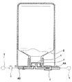
小型簡易コンプレッサ装置1は、図1、2に示すように、モータMにより回転駆動される回転軸11、この回転軸11にクランク12を介して取り付けられるロッド13と、このロッド13の端に設けるピストン14と、このピストンを往復動可能に収納するシリンダ室15を有するシリンダ16とからなる小型コンプレッサ10、前記小型コンプレッサ10の過圧を逃がすリリーフバルブ17を具えかつ前記小型コンプレッサ10の高圧空気をタイヤに送る空気送給手段18、及び前記モータMへの電気を取り入れる電源プラグ19を具えている。なお、モータMとして自動車の12V直流電源で作動するDCモータが使用される。
As shown in FIGS. 1 and 2, the small
さらに本形態では、小型簡易コンプレッサ装置1は、図1に示すように、前記モータM、回転軸11、小型コンプレッサ10、空気送給手段18を分離可能な上下のハウジング20A,20Bからなるハウジング20内に収納し、該ハウジング20には、前記電源プラグ19に接続される電気コード6Aと、前記空気送給手段18からのび、先端にシール・ポンプアップ装置3の接続口に装着可能な前記継手5aを有するホース4Aが延出している。なお電気コード6Aには、前記上のハウジング20A上面に設けるオンオフスイッチSWが介在している。
Further, in this embodiment, as shown in FIG. 1, the small
さらに、前記小型コンプレッサ10、空気送給手段18は、フレーム23に組み込まれて一体な空気吐出ユニット24を構成する。フレーム23は切欠き円筒状の囲壁部23Aの奥壁で前記回転軸11を枢支し、かつ回転軸11の奥壁背面への出軸で、図2に示す、前記モータMの出力軸のピニオン21に噛合するギア22を固着している。又回転軸11の前方への突出部により、図2に示すバランス付のクランク12を固定している。なお、モータMも前記奥壁にボルト固定でき、かつピニオン21、ギア22からなる減速機構により、モータMの回転を1/3〜1/8程度に減速して回転軸11に伝える。
Further, the
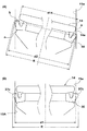
前記クランク12には、支持ピン26を介して前記ロッド13の一端を回転自在に枢支するとともに、ロッド13の他端には前記ピストン14が取り付けられ、本形態では、前記ロッド13とピストン14とは一体の軽量なFRPからなる。前記ピストン14の外周面14aには、リングシール30が取り付けられ、しかも、ピストン14には、図5(A)に示すように、該ピストン14を内外に奥壁15wを貫通して開放される通気孔31Aと、該通気孔31Aを、上面(反ロッド側を上と呼ぶときがある)からバネ性を有して閉じる、ゴム、合成樹脂、金属等の弾性体、またはコイルバネにより閉止付勢される薄板などの弁体31Bとを用いた吸気弁31が形成される。
One end of the
又このピストン14は、図2,3に示すように、前記フレーム23に一体な円筒状の前記シリンダ16のシリンダ室15に収納され、クランク12の回転によるロッド13の揺動往復動によりハ字の正、逆傾きを交互に繰り返しつつピストン14が、シリンダ室15の内周面15aに前記リングシール30を介して接しつつ下死点(図5(B))から、ピストン14が傾きつつ(図5(C))、シリンダ室15の奥壁15wに近づき上死点(図示せず)となることにより、圧縮に際して吸気弁31が閉じられているシリンダ室15の空気を最高圧で圧縮し高圧空気を発生しうる。
2 and 3, the
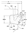
前記リングシール30は、ピストン14の前記正逆による、ピストン14とシリンダ室15の内周面15aとの間の間隙Gの変動に拘わらず効率的にシールする。このリングシール30は、ピストン14の外周面14aに設けた周溝33に嵌着され、この周溝33は、図7に示すように、ピストン14の中心軸と平行な底面33Aのロッド側,反ロッド側の両縁に、ロッド側に向くロッド側溝側面33Bと、反ロッド側に向く反ロッド側溝側面33Cとが末拡がり状に傾斜して形成されている。
The
前記ロッド側溝側面33Bと、反ロッド側溝側面33Cとの前記底面33Aと直角な半径線に対してなす角度α1、α2は、それぞれ半径方向に対して周溝33が広がる向きの、5゜〜20゜程度に設定している。なお前記角度α1,α2を同じとすることも、ロッド側溝側面33Bの角度α1を小として、圧縮時のピストン14の抗力を大とすることもでき、本形態では共に10゜程度に設定している。
Angles α1 and α2 formed with respect to a radial line perpendicular to the
なお周溝33の前記底面33Aの巾W33aは、例えば0.9〜3.6mm程度、好ましくは1.5〜2.5mm程度、本形態では1.8mm程度に形成され、前記外周面14aからの溝深さH33は、いずれも、前記底面33Aの巾W33aと略同程度の1.0〜4.0mm、好ましくは1.6〜2.3mm、本形態では、2.0mm程度としている。このように周溝33は、半径方向外側に向かい巾を広げる末広がり状に形成されるため、リングシール30を容易に取り付けでき、かつ作動時の逸脱を、リングシール30の形状と相俟ってシール効果を維持しつつ防止できる。
The width W33a of the
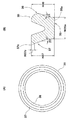
前記リングシール30は、図6(A)に示すように円環体であり、かつその中心軸を含む断面を図6(B)に示すように、基面35aが平坦かつ断面略矩形の基部35と、該基部35の半径方向の内外端部から略ハ字状に開脚してのびることによりその間でV字状溝を形成する内のリップ部36と、外のリップ部37とを具える略V字をなす。又、内のリップ部36と、外のリップ部37とは根元部において同厚さに形成されるが、前記V字状溝とは反対側の各表面(内のリップ部36については内面、外のリップ部37については外面ということがある)では、内のリップ部36は先端部外膨らみの円弧状曲面とし、他方、外のリップ部37の外面には80〜140゜の角度で交わる交点37cが先端からその全高さH37の5〜15%を隔てる位置H37cに形成される。
The
又自由状態において、内のリップ部36の内面と外のリップ部37の外面は基部35の基面35aと直角な2等分線と平行な線に対してなす角度β1,β2を10゜〜40゜程度、好ましくは15〜30゜、本形態では共に22゜の角度でリップ部端が開口する向きで傾斜している。
In the free state, the inner surface of the
又前記基部35の基面35aの巾W35aは、例えば周溝33の前記ロッド側溝側面33Bの該側面に沿う長さと等しくして、図7に示すごとく基面35aを該側面33Bに着座させる。又基面35aが着座した状態において、前記内のリップ部36は周溝33の底面33Aに接するのがよく、そのため、前記角度β1を、前記周溝の前記角度α1以上かつ(α1+15゜)以下程度に設定し、基面35aの着座、内のリップ部36の挿入により外のリップ部37が半径方向内側へ倒れ込むのを防ぐ。さらに、図7に示すように、内のリップ部36は、周溝33に装着後の状態において、周溝33の反ロッド側溝側面33Cとの間で押圧され、挟持されるように、その高さH36を周溝33の該部分の巾よりも2〜10%の範囲で大きく設定している。
The width W35a of the
又周溝33へのリングシール30の取付けにより、前記周溝33の反ロッド側溝側面33Cは前記角度α2で反ロッド側に、前記外のリップ部37から離れる向きに傾斜している。しかも、外のリップ部37も基部35の基面35aに対して角度β2で半径方向外に傾斜している。その結果、高さH37を内のリップ部36の高さH36と同じとしたときにも、外のリップ部37の先端は該反ロッド側溝側面33Cから距離N(図7に示す)を高さ方向に離間でき、半径方向内向きへの折曲げ時において、反ロッド側溝側面33Cとの衝合を防止される。又これにより、外のリップ部37は、その外表面の前記交点37cは、ピストン14の外周面14aから半径方向外側に距離Lを全周に亘って突出する。即ち、ピストン14がシリンダ室15に挿入されないリング非挿入状態である自由状態において、外のリップの外径Rは、前記ピストン14の外周面14aの直径d14aに前記距離Lの2倍を付加したものとなる(R=d14a+2・L)。
Further, by attaching the
なお外のリップ部37の前記交点37cからのびる両斜辺37c1,37c2がなす角度γを、自由状態において90〜130゜程度とし、かつ作動時において、その2等分線がシリンダ室15の内周面15aと垂直となるように設定するのが潤滑性から好ましく、内周面15aとの接触を、往復に際しての均等化を意図とする。
The angle γ formed by the two oblique sides 37c1 and 37c2 extending from the
なお、前記距離Lの設定に関して、まずピストン14の外周面14aの直径d14aは、ピストン14の最大傾斜時においても、ピストン14の外周面14aと、シリンダ室15の内周面15aとの間で間隙aを維持し衝合が生じないように、上下方向厚さ、縁部の面取りなどを考慮し、前記外周面14aの直径d14aが設定される(図8(A))。
Regarding the setting of the distance L, first, the diameter d14a of the outer
ところで、ピストン14の最大傾斜時においては、そのときのリングシール30の交点37cを通る平面bは、シリンダ室15の内周面15aと楕円となり、その長軸の長径d2(短径はシリンダ室15の内径d1)部分でもシールすることが不可欠であり、そのため、前記長径d2よりも大、かつ径比R/d2を1.01〜1.15としている。これにより、最大傾斜時においても、図8(A)に示すように、圧縮空気のもれを減じる。なお、1.15を越えるときには、通常、過度に接触圧を高め、作動効率、耐摩耗性を低下させる。1.02以下であるときには空気漏れを生じやすい。このましくは1.03〜1.08程度とする。
By the way, when the
又係るリングシール30は係る構成を具えることにより、シリンダ室15の圧縮空気が外のリップ部37に作用し、その圧力が該外のリップ部37を外に押出し、シリンダ室15の内周面15aと接することにより、リングシール30のめくれ、隙間からのリークを防ぎうる。さらにピストンのコジレの発生を減じて空気洩れを減じ、かつ作動を円滑とするとともに、経年変形によるシール力の低減を減じる。さらに、ピストン14が最も傾く時にシリンダ室15の内周面15aとの間に生じる最大の隙間を外のリップ部37が確実に塞ぐことができる。
Further, the
前記リングシール30は、水素化ニトリルゴム(HNBR)、ニトリルゴム(NBR)、ブタジエンゴム(BR)、スチレンブタジエンゴム(SBR)、クロロプレンゴム(CR)、エチレンプロピレンゴム(EPDM)などのゴム材料を用いて形成する。特に水素化ニトリルゴム(HNBR)は弾性、耐熱性に富むため−30゜C〜80℃の広い範囲の温度環境でもシール性を発揮でき、内外のリップ部36、37を有する断面略U字状のリングシール30に好適に用いることができる。
The
またリングシール30は、水素化ニトリルゴム(HNBR)を含むニトリルゴムの場合において、硬さが例えばデュロメータA65°〜80°、本形態ではデュロメータA74°に形成される。下限についてより好ましくはデュロメータA70°以上が良い。上限についてより好ましくはデュロメータA75°以下が良い。硬度がデュロメータA80°を越えるとピストン6上下動に対する抵抗が過大となり、65°未満ではシール圧が不足して高圧空気の圧力低下を招く。
Further, in the case of nitrile rubber including hydrogenated nitrile rubber (HNBR), the
さらに、シリンダ室15の内周面15aと、リングシール30との摺動に伴う摩擦抵抗を減じてピストン14の昇降をスムースとするため、合成炭化水素油 (PAO)、鉱油、フッ素系合成油、ジエステル、ポリオールエステル、ポリグリコール、フェニルエーテル、シリコーンなどのグリースが潤滑剤として使用される。前記合成炭化水素油(PAO)は、例えば−30゜Cの低温から80℃の高温に亘る温度域で優れた耐久性を発揮するため、あらゆる温度環境下で使用されるタイヤパンク応急修理キットS用の小型簡易コンプレッサ装置1のグリースとして好適に採用できる。
Furthermore, in order to reduce the frictional resistance accompanying sliding between the inner
前記した一体な空気吐出ユニット24は、前記のように、小型コンプレッサ10と、空気送給手段18とを、フレーム23に組み込み、空気送給手段18は、前記フレーム23がなす前記シリンダ室15の奥壁15wに設けた圧縮空気の入口15eと、該入口15eを囲みサージタンク空間42を形成する囲み壁43とを形成している。
As described above, the integrated air discharge unit 24 incorporates the
又この囲み壁43には、シリンダ室15で生じる高圧空気を、図3,4で示したシール・ポンプアップ装置3に送るホース4Aの接続用の継手を取付ける取付け口43aと、前記リリーフバルブ17の取付け口43bと、前記上のハウジング20Aの上面の圧力計44へのホース4Bを取付けるための継手の取付け用の取付け口43cとを穿設している。
The
なお、前記リリーフバルブ17は、図9に示すように、前記取付け口43bに形成され空気流入側に向かって先細となる弁座50aと、後端部のネジ50bと、弁座50aに当接するシールを有する弁軸51と、前記ネジ50b後端に螺着される調節ネジ52とを具え、調節ネジ52との間に、前記シールの押し付け力を付与する押しバネ53を設けている。これにより前記調節ネジ52の螺進退によりシール強さを調節し、サージタンク空間42の内圧が所定値を越えることにより、シールが弁座50aを開き(図9(B))内圧を逃がす。即ち、リリーフバルブ17の設定リリーフ圧(本形態では例えば350kPaとする)を越えるとリリーフバルブ17が開き,小型コンプレッサ10、空気送給手段18、シール・ポンプアップ装置3、他のホース、及びタイヤに至る高圧空気部の、過圧による損傷を防止し、かつタイヤ充填内圧を設定できる。
As shown in FIG. 9, the
前記押しバネ53はSUS304等を含むステンレス鋼、ピアノ線、バネ鋼、工具鋼などを用いて形成される。なおステンレス鋼の場合、焼き入れ加工されたステンレス鋼を用いると繰返し負荷に対するバネ力の劣化が小さくなるため、長期間使用されてもリリーフ圧を維持することが可能となる。なお、リリーフバルブ17をシリンダーヘッド部より10cm程度離して設置すると、押しバネ53が高温化するシリンダから伝わる熱により劣化するのを防ぐことができる。
The
前記電源プラグ19は、自動車のバッテリーに通じるシガーライターソケットに接続され、該電源プラグ19は、図10(A)に示すように、前記電気コードが接続されるプラグ本体55に、前記電気コードに連通し該プラグ本体55先端の+側端子ピン56と、プラグ本体55の先端寄りに設けられた−側端子接続バネ57とを設けている。前記−側端子接続バネ57は図10(B)に示すように、後端の連結片57aに互いに平行な複数(本形態では4個)の脚片57b・・を設け、かつ脚片57b・・の先端部分を中心線両側で中央円弧を有して山形に折曲げかつプラグ本体55の中心軸と平行に取り付けて、プラグ本体55の側面から隆起する突部57cを形成している。
The
このように、複数の突部をプラグ本体55に沿って設け、かつその中心軸と同芯としているため、電源プラグ19をシガーライターソケットに挿入する際、−側端子接続バネ57の前記突部57cが円滑にシガーライターソケットに内周面に圧接し、シガーライターソケットへの挿入、引抜き、さらには電気コードの捻れ直しのための回転等の動作を円滑とし、かつ抜け落ちが防止される。なお、前記−側端子接続バネ57はりん青銅、銅、ステンレス鋼などを用いて成形されるが、特にJISC5191に基づいてNiメッキ処理したりん青銅を用いた−側端子接続バネ57は、電気伝導度が高く、高強度でばね性、耐摩耗性に優れるとともに化学的腐食にも強く、また前記挿入、引抜く際の抵抗を最適化できる点で好ましい。
Thus, since the plurality of protrusions are provided along the
図4〜6に示す形状のリングシール(U字状という)を用いた場合と、従来の中実のOリングを用いた場合(比較例1)とを比較した。実施例1は材質としてNBR(デュロメータ硬度Aが74゜)、実施例2は、同形状かつシリコンゴムを用いている。これらを25℃、−30℃の2種類の環境下で、12V電源を用いてタイヤサイズ225/60R16のタイヤを250kPaまで昇圧するための時間を測定した。測定結果を表1に示すように実施例1、2は、比較例1に比べ特に低温時での昇圧時間が減じているのがわかる。低温時の昇温時間は特に好ましい性能といえる。
なお、実施例1,2で用いたリングシールは、周溝33の底面33Aの巾W33aが1.8mm、開口部の巾W33dが2.5mm、最大傾斜縮み代を0.05程度、ピストンの最大傾き角度を20゜としている。
The case where a ring seal (referred to as a U-shape) having the shape shown in FIGS. 4 to 6 was used and the case where a conventional solid O-ring was used (Comparative Example 1) were compared. Example 1 uses NBR as the material (durometer hardness A is 74 °), and Example 2 uses the same shape and silicon rubber. The time for pressure-increasing the tire of tire size 225 / 60R16 to 250 kPa using a 12V power source was measured under two types of environments of 25 ° C. and −30 ° C. As shown in Table 1, it can be seen that Examples 1 and 2 have a reduced pressurization time especially at low temperatures compared to Comparative Example 1. It can be said that the temperature rising time at low temperature is a particularly preferable performance.
In the ring seals used in Examples 1 and 2, the width W33a of the

表2の仕様に基づきグリースとして合成炭化水素油、鉱油、フッ素系合成油を各々使用した参考例1〜3を用い、80℃、−30℃の二種類の環境下で、250kPaでの運転5分と25分の運転停止とを100時間繰返す耐久試験を行った。その結果高温、低温いずれの環境下においても参考例1は損傷が認められなかった。
Based on the specifications of Table 2, using
表3の仕様に基づき−側端子接続バネ57をりん青銅を用い突部の断面形状を山型とした電源プラグ、材質をスチールに替えた電源プラグ、平型に変更した電源プラグを参考例4〜6として、これらを車のシガーライターソケットに挿入、引抜き、回転させたときの力、トルクを測定したところ、参考例5は着脱が硬く、参考例6は回転し難くいのに比べ、参考例4の操作性が最も良好であった。
Based on the specifications in Table 3, the negative side
1 小型簡易コンプレッサ装置
2 シーリング缶
3 シール・ポンプアップ装置
4 ロッド
10 小型コンプレッサ
11 回転軸
12 クランク
13 ロッド
14 ピストン
15 シリンダ室
15a 内周面
16 シリンダ
17 リリーフバルブ
18 空気送給手段
19 電源フラグ
20 ロッド側溝側面
21 反ロッド側溝側面
S タイヤパンク応急修理キット
30 シールリング
33 周溝
33A 底面
33b ロッド側溝側面
33c 反ロッド側溝側面
36 内のリップ部
37 外のリップ部
37c 交点
M モータ
1 Small and simple compressor device 2 Sealing can 3 Seal / pump-up device
4 Rod
DESCRIPTION OF
S tire puncture
33A bottom surface 33b rod side groove side surface 33c anti-rod side
Claims (4)
この回転軸にクランクを介して取り付けられるロッドと、このロッド端のピストンと、このピストンを往復動可能に収納するシリンダ室を有するシリンダとからなる小型コンプレッサ、
前記小型コンプレッサの過圧を逃がすリリーフバルブを具えかつ前記小型コンプレッサのコンプレッサ室の高圧空気をタイヤに送る空気送給手段、
及び前記モータへの電気を取り入れる電源プラグを具えるとともに、
前記ロッドとピストンとは一体なFRPからなりかつ前記ピストンは前記シリンダ室に空気を取り込みしかも加圧に際して閉止する吸気弁を具え、
しかも前記ピストンは、ピストンとシリンダ室の内周面との間をシールするリングシールを配すると共に、
該リングシールは、前記ピストンの外周面に設けた周溝のロッド側溝側面と当接する基部と、該基部の半径方向内外から反ロッド方向にのびる内のリップ部と、外のリップ部とを有することを特徴とする小型簡易コンプレッサ装置。
A rotating shaft driven to rotate by a motor,
A small compressor comprising a rod attached to the rotating shaft via a crank, a piston at the end of the rod, and a cylinder having a cylinder chamber for reciprocatingly moving the piston;
An air supply means comprising a relief valve for releasing the overpressure of the small compressor and sending high pressure air from the compressor chamber of the small compressor to the tire;
And a power plug for taking in electricity to the motor,
The rod and piston are made of an integral FRP, and the piston has an intake valve that takes air into the cylinder chamber and closes when pressurized.
Moreover, the piston has a ring seal that seals between the piston and the inner peripheral surface of the cylinder chamber ,
The ring seal, and the rod-side groove flank of the circumferential groove provided on the outer peripheral surface of the piston abutting the base, and the lip portion of which extends in the counter-rod direction from the radially inner and outer base portion and an outer lip portion A small and simple compressor device characterized by having.
Priority Applications (5)
| Application Number | Priority Date | Filing Date | Title |
|---|---|---|---|
| JP2004163526A JP4392292B2 (en) | 2004-06-01 | 2004-06-01 | Compact simple compressor device |
| DE602005008137T DE602005008137D1 (en) | 2004-06-01 | 2005-05-24 | Compact compressor unit |
| EP05011262A EP1605162B1 (en) | 2004-06-01 | 2005-05-24 | Compact simplified compressor apparatus |
| US11/139,620 US7547201B2 (en) | 2004-06-01 | 2005-05-31 | Compact simplified compressor apparatus |
| CNB2005100732180A CN100368684C (en) | 2004-06-01 | 2005-06-01 | Compact simplified compressor apparatus |
Applications Claiming Priority (1)
| Application Number | Priority Date | Filing Date | Title |
|---|---|---|---|
| JP2004163526A JP4392292B2 (en) | 2004-06-01 | 2004-06-01 | Compact simple compressor device |
Publications (2)
| Publication Number | Publication Date |
|---|---|
| JP2005344570A JP2005344570A (en) | 2005-12-15 |
| JP4392292B2 true JP4392292B2 (en) | 2009-12-24 |
Family
ID=34936895
Family Applications (1)
| Application Number | Title | Priority Date | Filing Date |
|---|---|---|---|
| JP2004163526A Active JP4392292B2 (en) | 2004-06-01 | 2004-06-01 | Compact simple compressor device |
Country Status (5)
| Country | Link |
|---|---|
| US (1) | US7547201B2 (en) |
| EP (1) | EP1605162B1 (en) |
| JP (1) | JP4392292B2 (en) |
| CN (1) | CN100368684C (en) |
| DE (1) | DE602005008137D1 (en) |
Families Citing this family (58)
| Publication number | Priority date | Publication date | Assignee | Title |
|---|---|---|---|---|
| TWI235790B (en) * | 2004-02-29 | 2005-07-11 | Wen-Shan Chou | Miniature simple air filling device |
| CN2851637Y (en) * | 2005-06-17 | 2006-12-27 | 杨琪 | Portable gas-charging machine for tyre |
| DE102005060320A1 (en) * | 2005-12-16 | 2007-06-21 | Continental Aktiengesellschaft | compressor unit |
| JP5004672B2 (en) * | 2006-05-31 | 2012-08-22 | 株式会社日立産機システム | Swing type compressor |
| CN101501338B (en) * | 2006-06-08 | 2012-11-14 | 拉里·阿尔文·许茨勒 | Reciprocating compressor or pump and a portable tool powering system including a reciprocating compressor |
| GB2439384B (en) * | 2006-06-19 | 2009-08-12 | Allan Hopkins | Pump Apparatus |
| ITTO20060674A1 (en) * | 2006-09-21 | 2008-03-22 | Tek Srl | COMPRESSOR GROUP PERFECTED FOR A REPAIR AND INFLATION KIT FOR INFLATABLE ITEMS |
| US20090010774A1 (en) * | 2007-07-02 | 2009-01-08 | Fish Robert D | Air Compressor and Reservoir For Topping Off Low Pressure Tires |
| CN101429935B (en) * | 2007-11-07 | 2012-03-07 | 周文三 | Piston body structure of air compressor |
| JP5230995B2 (en) * | 2007-11-09 | 2013-07-10 | 周 文三 | Air compressor having an improved seal ring |
| CN101977755A (en) * | 2008-03-25 | 2011-02-16 | 住友橡胶工业株式会社 | Tire puncture repair apparatus |
| JP4369981B2 (en) | 2008-04-30 | 2009-11-25 | 住友ゴム工業株式会社 | Compressor device |
| JP2010261556A (en) * | 2009-05-11 | 2010-11-18 | Bridgestone Corp | Safety valve and compressor |
| JP5285536B2 (en) * | 2009-08-18 | 2013-09-11 | 周 文三 | air compressor |
| IT1395661B1 (en) * | 2009-08-21 | 2012-10-16 | Tek Global Srl | CONTAINER FOR A SEALANT LIQUID AND REPAIR KIT INCLUDING SUCH A CONTAINER |
| JP5285539B2 (en) * | 2009-08-24 | 2013-09-11 | 住友ゴム工業株式会社 | Compressor device |
| WO2011055632A1 (en) | 2009-11-04 | 2011-05-12 | 住友ゴム工業株式会社 | Puncture repair kit |
| CN102686384B (en) * | 2009-11-04 | 2014-08-06 | 住友橡胶工业株式会社 | Puncture repair kit |
| US8684046B2 (en) * | 2009-11-04 | 2014-04-01 | Sumitomo Rubber Industries, Ltd. | Puncture repair kit |
| EP2353848B1 (en) * | 2010-02-09 | 2013-10-16 | Wen-San Jhou | Device for sealing and inflating inflatable object |
| KR101187377B1 (en) | 2010-03-03 | 2012-10-04 | 웬-산 초우 | Air injection type air compressor for repairing tire |
| JP5731799B2 (en) * | 2010-11-10 | 2015-06-10 | 住友ゴム工業株式会社 | Punk repair kit |
| JP5353873B2 (en) * | 2010-12-25 | 2013-11-27 | マックス株式会社 | Compressor control device |
| US8925594B2 (en) | 2011-01-04 | 2015-01-06 | Bell Automotive Products, Inc. | Portable tire inflator and reflective device |
| US20120168031A1 (en) * | 2011-01-04 | 2012-07-05 | Ohm Patrick L | Hand-held tire inflator |
| JP5374524B2 (en) * | 2011-01-26 | 2013-12-25 | 住友ゴム工業株式会社 | Compressor device |
| CN102619726B (en) * | 2011-01-28 | 2015-08-05 | 周文三 | Air compressor |
| CN104564605B (en) * | 2011-01-28 | 2017-07-28 | 周文三 | A kind of air compressor |
| JP5681550B2 (en) * | 2011-04-13 | 2015-03-11 | 住友ゴム工業株式会社 | Compressor device |
| US20110252960A1 (en) * | 2011-04-27 | 2011-10-20 | Flight Medical Innovations Ltd. | Mechanical ventilator |
| US8733270B2 (en) * | 2011-11-28 | 2014-05-27 | Chi-Wen Chen | Pressure indication device of inflation machine |
| EP2815875B1 (en) | 2012-02-16 | 2018-04-11 | Wen-San Jhou | Vehicle-mounted air compressor device |
| DE202012101110U1 (en) * | 2012-03-28 | 2012-04-26 | Continental Reifen Deutschland Gmbh | Breakdown kit for motor vehicles |
| CN104755760B (en) * | 2012-10-26 | 2017-05-31 | 住友橡胶工业株式会社 | Compressor assembly and the puncture repair kit using the compressor assembly |
| US9302654B2 (en) * | 2013-01-25 | 2016-04-05 | Illinois Tool Works Inc. | Device for dispensing tire sealant |
| CN104956085B (en) * | 2013-02-07 | 2017-09-05 | 周文三 | Air compressor is constructed |
| US9057656B2 (en) * | 2013-04-25 | 2015-06-16 | Chi-Wen Chen | Pressure indication device of inflation machine with safety pressure relief |
| DE102013105217A1 (en) * | 2013-05-22 | 2014-11-27 | Illinois Tool Works Inc. | Compressor for generating a pressure medium |
| CN103470471A (en) * | 2013-08-05 | 2013-12-25 | 厉煊 | Portable air pump |
| TW201507900A (en) * | 2013-08-27 | 2015-03-01 | Active Tools Int Hk Ltd | Cylinder seat of air compressor of tire repair machine |
| GB201402528D0 (en) * | 2014-02-13 | 2014-04-02 | Delphi Int Operations Luxembourg Sarl | High pressure fuel pump |
| DE102014205071A1 (en) * | 2014-03-19 | 2015-09-24 | Continental Reifen Deutschland Gmbh | Device for sealing and inflating inflatable objects |
| TWI575159B (en) * | 2014-05-26 | 2017-03-21 | 周文三 | Portable pump module |
| TWI577889B (en) * | 2014-10-07 | 2017-04-11 | 周文三 | Improved air compressor |
| CN104454442B (en) * | 2014-12-31 | 2018-03-06 | 东莞瑞柯电子科技股份有限公司 | A kind of mini air compressor |
| JP5867637B1 (en) * | 2015-02-23 | 2016-02-24 | 横浜ゴム株式会社 | Puncture repair liquid container |
| DE102015203970A1 (en) * | 2015-03-05 | 2016-09-08 | Continental Reifen Deutschland Gmbh | Portable compressor device |
| US10731637B2 (en) | 2015-07-27 | 2020-08-04 | Walmsley Developments Pty Ltd | Portable pump |
| CA2997192A1 (en) * | 2015-09-02 | 2017-03-09 | Active Tools International (Hk) Ltd. | Air inflating device and tire repair machine comprising same |
| DE102016209302A1 (en) * | 2016-05-30 | 2017-12-14 | Continental Reifen Deutschland Gmbh | Method for sealing and inflating inflatable articles |
| JP1572080S (en) * | 2016-10-03 | 2017-03-21 | ||
| CN107244195A (en) * | 2017-05-22 | 2017-10-13 | 宁波高新区甬航工业设计有限公司 | Inflators a kind of portable and with illumination functions |
| ES2784976T3 (en) | 2017-06-21 | 2020-10-02 | Walmsley Dev Pty Ltd | Portable pump |
| US10933844B2 (en) * | 2018-06-21 | 2021-03-02 | Illinois Tool Works Inc. | Vehicle tire inflation compressor for powered data ports |
| US11279184B2 (en) | 2018-12-26 | 2022-03-22 | Pacific Industrial Co., Ltd. | Fuel solution introducing method and lubricant |
| EP3698990B1 (en) | 2018-12-26 | 2021-12-15 | Pacific Industrial Co., Ltd. | Transmitter |
| CN114787542A (en) * | 2019-12-11 | 2022-07-22 | Ntn株式会社 | Shaft seal |
| DE102022208268A1 (en) * | 2022-08-09 | 2024-02-15 | Continental Reifen Deutschland Gmbh | Compressor systems for roadside assistance kits |
Family Cites Families (30)
| Publication number | Priority date | Publication date | Assignee | Title |
|---|---|---|---|---|
| US2081040A (en) * | 1932-06-17 | 1937-05-18 | J S Abercrombie | Packing |
| US2360731A (en) * | 1942-08-15 | 1944-10-17 | Maytag Co | Wedge-ring seal |
| US3040712A (en) * | 1959-04-17 | 1962-06-26 | Firco Inc | Cylinder, piston and rod assembly |
| US4027816A (en) * | 1975-04-18 | 1977-06-07 | Bowen Tools, Inc. | Seal assembly |
| DE2951112C2 (en) * | 1979-12-19 | 1983-10-13 | Messerschmitt-Bölkow-Blohm GmbH, 8000 München | Connecting rod made of fiber-reinforced plastic for power machines |
| SE430915B (en) * | 1982-06-04 | 1983-12-19 | Volvo Flygmotor Ab | CALVING DEVICE FOR HYDRAULIC MECHANISMS, SEPARATELY SADANA WITH VERY HIGH WORKING PRESSURE |
| FR2532994B1 (en) * | 1982-09-11 | 1988-02-26 | Becker Erich | OSCILLATING PISTON PUMP |
| DE3233854A1 (en) * | 1982-09-11 | 1984-03-15 | Erich 7812 Bad Krozingen Becker | Reciprocating piston pump |
| GB8500683D0 (en) * | 1985-01-11 | 1985-02-13 | Secretary Trade Ind Brit | Piston & connecting road combination |
| JPS62251568A (en) * | 1986-04-24 | 1987-11-02 | Mitsubishi Rayon Co Ltd | Fiber reinforced plastic small-sized piston and manufacture thereof |
| US5092125A (en) * | 1987-10-29 | 1992-03-03 | Automotive Products Plc | Seal |
| US6152014A (en) * | 1989-03-17 | 2000-11-28 | Willimczik; Wolfhart | Rotary piston machines |
| KR920001704Y1 (en) | 1989-11-15 | 1992-03-09 | 이상우 | Arrangement for discharge lamps |
| US5064359A (en) * | 1990-07-16 | 1991-11-12 | Ingersoll-Rand Company | Annular support for a seal for a tilt piston |
| DE4339652C2 (en) * | 1992-12-17 | 2003-10-30 | Zf Sachs Ag | Hydraulically actuated release slave cylinder for a motor vehicle friction clutch |
| US5509670A (en) * | 1994-10-28 | 1996-04-23 | The Texacone Company | Packing member with reduced friction |
| DE19518875A1 (en) * | 1995-05-23 | 1996-11-28 | Lothar Wanzke | Piston with connecting rod |
| DE19549592C5 (en) * | 1995-07-11 | 2006-12-14 | Sumitomo Rubber Industries Ltd., Kobe | Device for sealing and inflating tires in the event of breakdowns |
| JPH11325245A (en) * | 1998-05-18 | 1999-11-26 | Aisin Seiki Co Ltd | Swing piston |
| JP3802987B2 (en) * | 1998-08-06 | 2006-08-02 | 自動車電機工業株式会社 | Portable electric air pump |
| JP2000238144A (en) * | 1999-02-17 | 2000-09-05 | Sumitomo Rubber Ind Ltd | Apparatus for sealing and pumping up tire |
| US6189894B1 (en) * | 1999-04-19 | 2001-02-20 | The Texacone Company | Urethane packing member with improved geometric configuration |
| JP2001271744A (en) * | 2000-03-24 | 2001-10-05 | Denso Corp | Air compressor |
| JP3082724U (en) * | 2001-06-15 | 2001-12-26 | 文三 周 | air compressor |
| CN2526603Y (en) * | 2001-08-20 | 2002-12-18 | 李勇涛 | Semi-armoured sealer |
| DE10151542B4 (en) * | 2001-10-23 | 2006-12-28 | Carl Freudenberg Kg | Complete piston |
| DE60224302T2 (en) * | 2001-11-15 | 2008-12-18 | Even Honour International Ltd. | APPARATUS FOR SEALING AND BUBBING AN INFLATABLE OBJECT |
| DE10219926A1 (en) * | 2002-05-03 | 2003-11-20 | Opel Adam Ag | Tire Repair System |
| US7017914B1 (en) * | 2002-10-15 | 2006-03-28 | Dana Corporation | Piston assembly and method of manufacture |
| CN2592899Y (en) * | 2002-12-11 | 2003-12-17 | 周文三 | Aircompressor piston body structure improvement |
-
2004
- 2004-06-01 JP JP2004163526A patent/JP4392292B2/en active Active
-
2005
- 2005-05-24 DE DE602005008137T patent/DE602005008137D1/en active Active
- 2005-05-24 EP EP05011262A patent/EP1605162B1/en active Active
- 2005-05-31 US US11/139,620 patent/US7547201B2/en active Active
- 2005-06-01 CN CNB2005100732180A patent/CN100368684C/en active Active
Also Published As
| Publication number | Publication date |
|---|---|
| JP2005344570A (en) | 2005-12-15 |
| CN100368684C (en) | 2008-02-13 |
| EP1605162A3 (en) | 2006-11-29 |
| US20050265873A1 (en) | 2005-12-01 |
| DE602005008137D1 (en) | 2008-08-28 |
| CN1704584A (en) | 2005-12-07 |
| EP1605162B1 (en) | 2008-07-16 |
| US7547201B2 (en) | 2009-06-16 |
| EP1605162A2 (en) | 2005-12-14 |
Similar Documents
| Publication | Publication Date | Title |
|---|---|---|
| JP4392292B2 (en) | Compact simple compressor device | |
| TWI235790B (en) | Miniature simple air filling device | |
| EP2386759B1 (en) | Rocking piston type compressor | |
| US9243639B2 (en) | Scroll compressor including a sealing member | |
| US20110277877A1 (en) | Device for delivering a gas | |
| EP1321499B1 (en) | Sealing material for use in seal member in compressor and compressor including the same | |
| CN101607390B (en) | Electrically operated pressing machine tool | |
| US20130032263A1 (en) | Diaphragm pump for self-inflating tire | |
| US20110076164A1 (en) | Air compressor having tilted piston | |
| CN111156152A (en) | Air pump | |
| JP3195506U (en) | Compressor unit | |
| TWM258186U (en) | Compact and simple air filling device | |
| CN205478645U (en) | Actuating cylinder of reciprocating compressor gas flow regulating system | |
| CN201818461U (en) | Portable air pump | |
| EP2320086B1 (en) | Air compressor having tilted piston | |
| EP3835586A1 (en) | Sealing structure and scroll air compressor having same | |
| CN110439874A (en) | A kind of rubber diaphragm life test air cylinder device | |
| CN210829640U (en) | Portable inflator pump | |
| CN211819843U (en) | Air pump | |
| CN210829639U (en) | Improved inflator pump | |
| CN217272623U (en) | Install convenient pipeline seal structure for air compressor | |
| CN218844676U (en) | Electric submersible pump with anti-deviation structure | |
| JP6170382B2 (en) | Reciprocating compressor | |
| CN203635674U (en) | Device used for removing dents from vehicle body | |
| JP2003207052A (en) | U-shaped seal and sealing device |
Legal Events
| Date | Code | Title | Description |
|---|---|---|---|
| A621 | Written request for application examination |
Free format text: JAPANESE INTERMEDIATE CODE: A621 Effective date: 20070228 |
|
| A977 | Report on retrieval |
Free format text: JAPANESE INTERMEDIATE CODE: A971007 Effective date: 20090428 |
|
| A131 | Notification of reasons for refusal |
Free format text: JAPANESE INTERMEDIATE CODE: A131 Effective date: 20090512 |
|
| A521 | Request for written amendment filed |
Free format text: JAPANESE INTERMEDIATE CODE: A523 Effective date: 20090630 |
|
| TRDD | Decision of grant or rejection written | ||
| A01 | Written decision to grant a patent or to grant a registration (utility model) |
Free format text: JAPANESE INTERMEDIATE CODE: A01 Effective date: 20091006 |
|
| A01 | Written decision to grant a patent or to grant a registration (utility model) |
Free format text: JAPANESE INTERMEDIATE CODE: A01 |
|
| A61 | First payment of annual fees (during grant procedure) |
Free format text: JAPANESE INTERMEDIATE CODE: A61 Effective date: 20091009 |
|
| FPAY | Renewal fee payment (event date is renewal date of database) |
Free format text: PAYMENT UNTIL: 20121016 Year of fee payment: 3 |
|
| R150 | Certificate of patent or registration of utility model |
Ref document number: 4392292 Country of ref document: JP Free format text: JAPANESE INTERMEDIATE CODE: R150 Free format text: JAPANESE INTERMEDIATE CODE: R150 |
|
| FPAY | Renewal fee payment (event date is renewal date of database) |
Free format text: PAYMENT UNTIL: 20121016 Year of fee payment: 3 |
|
| FPAY | Renewal fee payment (event date is renewal date of database) |
Free format text: PAYMENT UNTIL: 20131016 Year of fee payment: 4 |
|
| R250 | Receipt of annual fees |
Free format text: JAPANESE INTERMEDIATE CODE: R250 |
|
| R250 | Receipt of annual fees |
Free format text: JAPANESE INTERMEDIATE CODE: R250 |
|
| R250 | Receipt of annual fees |
Free format text: JAPANESE INTERMEDIATE CODE: R250 |
|
| R250 | Receipt of annual fees |
Free format text: JAPANESE INTERMEDIATE CODE: R250 |
|
| R250 | Receipt of annual fees |
Free format text: JAPANESE INTERMEDIATE CODE: R250 |
|
| R250 | Receipt of annual fees |
Free format text: JAPANESE INTERMEDIATE CODE: R250 |
|
| R250 | Receipt of annual fees |
Free format text: JAPANESE INTERMEDIATE CODE: R250 |
|
| R250 | Receipt of annual fees |
Free format text: JAPANESE INTERMEDIATE CODE: R250 |
|
| R250 | Receipt of annual fees |
Free format text: JAPANESE INTERMEDIATE CODE: R250 |
|
| S111 | Request for change of ownership or part of ownership |
Free format text: JAPANESE INTERMEDIATE CODE: R313117 |
|
| R250 | Receipt of annual fees |
Free format text: JAPANESE INTERMEDIATE CODE: R250 |
|
| R371 | Transfer withdrawn |
Free format text: JAPANESE INTERMEDIATE CODE: R371 |
|
| S111 | Request for change of ownership or part of ownership |
Free format text: JAPANESE INTERMEDIATE CODE: R313117 |
|
| R350 | Written notification of registration of transfer |
Free format text: JAPANESE INTERMEDIATE CODE: R350 |
|
| R250 | Receipt of annual fees |
Free format text: JAPANESE INTERMEDIATE CODE: R250 |