JP4391925B2 - Atomic force microscope - Google Patents
Atomic force microscope Download PDFInfo
- Publication number
- JP4391925B2 JP4391925B2 JP2004342494A JP2004342494A JP4391925B2 JP 4391925 B2 JP4391925 B2 JP 4391925B2 JP 2004342494 A JP2004342494 A JP 2004342494A JP 2004342494 A JP2004342494 A JP 2004342494A JP 4391925 B2 JP4391925 B2 JP 4391925B2
- Authority
- JP
- Japan
- Prior art keywords
- cantilever
- vibration
- sample
- glass plate
- liquid
- Prior art date
- Legal status (The legal status is an assumption and is not a legal conclusion. Google has not performed a legal analysis and makes no representation as to the accuracy of the status listed.)
- Expired - Fee Related
Links
- 239000000523 sample Substances 0.000 claims description 79
- 239000011521 glass Substances 0.000 claims description 61
- 239000007788 liquid Substances 0.000 claims description 37
- 230000005540 biological transmission Effects 0.000 claims description 31
- 238000001514 detection method Methods 0.000 claims description 21
- 230000005284 excitation Effects 0.000 claims description 18
- 239000011810 insulating material Substances 0.000 claims description 15
- 239000011345 viscous material Substances 0.000 claims description 7
- 238000006073 displacement reaction Methods 0.000 description 23
- 230000003287 optical effect Effects 0.000 description 12
- 230000007274 generation of a signal involved in cell-cell signaling Effects 0.000 description 8
- 239000012472 biological sample Substances 0.000 description 3
- 238000000034 method Methods 0.000 description 3
- 230000004048 modification Effects 0.000 description 3
- 238000012986 modification Methods 0.000 description 3
- 230000002238 attenuated effect Effects 0.000 description 2
- 230000007423 decrease Effects 0.000 description 2
- 239000005871 repellent Substances 0.000 description 2
- 239000011347 resin Substances 0.000 description 2
- 229920005989 resin Polymers 0.000 description 2
- XLYOFNOQVPJJNP-UHFFFAOYSA-N water Substances O XLYOFNOQVPJJNP-UHFFFAOYSA-N 0.000 description 2
- 239000003153 chemical reaction reagent Substances 0.000 description 1
- 238000010586 diagram Methods 0.000 description 1
- 239000012212 insulator Substances 0.000 description 1
- 230000003993 interaction Effects 0.000 description 1
- 230000001678 irradiating effect Effects 0.000 description 1
- 238000013507 mapping Methods 0.000 description 1
- 239000000463 material Substances 0.000 description 1
- 238000005259 measurement Methods 0.000 description 1
- 239000002184 metal Substances 0.000 description 1
- 238000004651 near-field scanning optical microscopy Methods 0.000 description 1
- 230000002093 peripheral effect Effects 0.000 description 1
- 230000002940 repellent Effects 0.000 description 1
- 239000000126 substance Substances 0.000 description 1
- 230000005641 tunneling Effects 0.000 description 1
Images
Landscapes
- Length Measuring Devices With Unspecified Measuring Means (AREA)
Description
本発明は、原子間力顕微鏡に関する。 The present invention relates to an atomic force microscope.
走査型プローブ顕微鏡(SPM)は、機械的探針を機械的に走査して試料表面の情報を得る装置の総称であり、走査型トンネリング顕微鏡(STM)や原子間力顕微鏡(AFM)、走査型磁気力顕微鏡(MFM)、走査型電気容量顕微鏡(SCaM)、走査型近接場光顕微鏡(SNOM)、走査型熱顕微鏡(SThM)などを含んでいる。 A scanning probe microscope (SPM) is a general term for a device that mechanically scans a mechanical probe to obtain information on a sample surface, and includes a scanning tunneling microscope (STM), an atomic force microscope (AFM), and a scanning type. These include a magnetic force microscope (MFM), a scanning capacitance microscope (SCaM), a scanning near-field light microscope (SNOM), a scanning thermal microscope (SThM), and the like.
走査型プローブ顕微鏡は、機械的探針と試料とを相対的にXY方向にラスター走査し、所望の試料領域の表面情報を機械的探針を介して得てモニターTV上にマッピング表示することができる。 The scanning probe microscope can perform raster scanning of the mechanical probe and the sample in the XY directions relatively, obtain surface information of a desired sample region via the mechanical probe, and display the mapping on the monitor TV. it can.
走査型プローブ顕微鏡の中でも特に原子間力顕微鏡は、液体中の生きた生物試料の動く様子を光学顕微鏡よりも高い解像度で観察できる可能性があるとして注目されている。 Among the scanning probe microscopes, the atomic force microscope is attracting attention as it may be able to observe the movement of a living biological sample in a liquid with higher resolution than an optical microscope.
これまで生物試料の動く様子を観察できる装置は光学顕微鏡だけであるが、光学顕微鏡は回折限界のため光の波長以下の解像度で試料を観察することができない。 Until now, the optical microscope is the only device that can observe the movement of a biological sample. However, the optical microscope cannot observe the sample with a resolution lower than the wavelength of light because of the diffraction limit.
また電子顕微鏡は、ナノメートルオーダーの高い解像度を実現できるが、測定対象物を液体中に配置できないため、液体中の生きた生物試料を観察することはできない。 An electron microscope can achieve a high resolution on the order of nanometers, but cannot observe a living biological sample in a liquid because a measurement object cannot be placed in the liquid.
これに対して原子間力顕微鏡は、ナノメートルオーダーの高い解像度を期待でき、試料が液体中にあっても観察可能である。しかも、光学顕微鏡と組み合わせ易いことも注目されている理由の一つである。 On the other hand, the atomic force microscope can be expected to have a high resolution on the order of nanometers and can be observed even if the sample is in a liquid. Moreover, it is also one of the reasons that attention has been focused on being easy to combine with an optical microscope.
このような生体用原子間力顕微鏡では、カンチレバーの振動特性から試料探針間に働く相互作用を検出する方式(ACモード)を採用することが多い。それは、試料と探針の間に働く力を通常のモードに比べて弱く保つことができる利点があるからである。 In such an atomic force microscope for a living body, a system (AC mode) that detects an interaction between sample probes from the vibration characteristics of a cantilever is often employed. This is because there is an advantage that the force acting between the sample and the probe can be kept weak compared to the normal mode.
例えば図8は従来の生体用原子間力顕微鏡の一例の構成を示すブロック図である。また図9は図8に示されたステージを試料の側から見た図である。図8中のステージ周辺部は図9のVIII−VIII線に沿った断面で描かれている。 For example, FIG. 8 is a block diagram showing a configuration of an example of a conventional biological atomic force microscope. FIG. 9 is a view of the stage shown in FIG. 8 as viewed from the sample side. The stage peripheral part in FIG. 8 is drawn with the cross section along the VIII-VIII line of FIG.
図8と図9において、ステージ810は撥水処理されており、液体814を表面張力により保持できる。試料807はXYZスキャナー806によって保持され、液体814の中に置かれている。XYZスキャナー806はコントローラー802から出力される信号に基づいてX駆動回路803とY駆動回路804とZ駆動回路805により制御され、試料807をXYZ方向に走査し得る。
8 and 9, the
カンチレバー808は自由端に探針を有し、ステージ810に設けられたホルダー809によって保持され、試料807に正対するように液体814の中に置かれている。ホルダー809には圧電素子811が設けられている。圧電素子811はコントローラー802からの励振信号を受けて、カンチレバー808を所定の振幅と周波数で機械的に振動し得る。
The
カンチレバー808の変位を検出するための光てこセンサー816がステージ810の下部に配置されている。光てこセンサー816は、例えば特開2002−82037号公報に示されたものと同様に構成されており、対物レンズ815によって収束されたレーザー光ビーム813をステージ810によって支持された透過ガラス812を介してカンチレバー808の自由端に照射してカンチレバー808の変位を検出する。光てこセンサー816は、検出したカンチレバー808の変位を示す変位信号を振幅検出回路817に出力する。
An
振幅検出回路817は光てこセンサー816が出力するカンチレバー808の変位信号の振幅値を算出し、算出したカンチレバー808の振幅値を示す振幅信号をコントローラー802内のZ制御回路818に出力する。Z制御回路818は、振幅検出回路817から入力される振幅信号を一定に保つように、Z駆動回路805を介してXYZスキャナー806のZ方向変位を制御する。
The
この原子間力顕微鏡において、圧電素子811はコントローラー802からの励振信号を受けて、カンチレバー808の機械的共振周波数と所定の振幅でカンチレバー808を励振する。さらに、光てこセンサー816によりカンチレバー808の変位を検出し、カンチレバー808の振動振幅を一定に保つようにZ制御回路818とZ駆動回路805とによりXYZスキャナー806をZ方向(試料807の法線方向)に駆動して、XYZスキャナー806に保持された試料807のZ方向位置を制御する。
In this atomic force microscope, the
これに並行してX駆動回路803とY駆動回路804とによりXYZスキャナー806をXY方向に駆動して、試料807をカンチレバー808に対して二次元走査する。ホストコンピューター801は、X駆動回路803とY駆動回路804の駆動信号(すなわちXYZスキャナー806をX方向とY方向への変位させるための印加電圧信号)を試料表面の位置信号として取得するとともに、Z制御回路818の出力信号(すなわちXYZスキャナー806をZ方向へ変位させるための印加電圧信号)を試料表面の凹凸信号として取得し、取得した位置信号と凹凸信号とに基づいて画像を形成して表示する。
In parallel with this, the
上述したACモードの原子間力顕微鏡では、液体によるカンチレバーの振動の減衰が大きいため、カンチレバーの励振効率が非常に悪い。このため、カンチレバーを支持しているホルダーの振動特性がノイズとなって表れてしまうという不具合がある。これは機械的振動をホルダーを介してカンチレバーに伝達していることにより生じる現象である。 In the above-described AC mode atomic force microscope, the vibration of the cantilever is greatly attenuated by the liquid, so that the excitation efficiency of the cantilever is very poor. For this reason, there is a problem that the vibration characteristic of the holder supporting the cantilever appears as noise. This is a phenomenon caused by transmitting mechanical vibration to the cantilever through the holder.
特開平10−160742号公報は、この不具合の解決策のひとつとして、試料台(スライドガラス)を振動させ、試料を介してカンチレバーを励振させる手法を開示している。
しかし、特開平10−160742号公報の手法は試料を直接振動させるため、振動が試料に与える影響が懸念される。少なくとも試料を自然に近い状態から遠ざける方向にあるため推奨しにくい。また、この方法では、振動させる対象の質量が大きくなる傾向が強い。試料が載せられる台をダンパーで囲むことが主な原因である。その結果、走査の高速化に適していない。 However, since the method of Japanese Patent Laid-Open No. 10-160742 directly vibrates the sample, there is a concern about the influence of vibration on the sample. It is difficult to recommend at least because the sample is in a direction away from the natural state. In this method, the mass of the object to be vibrated tends to increase. The main cause is that the stage on which the sample is placed is surrounded by a damper. As a result, it is not suitable for increasing the scanning speed.
本発明は、このような実状を考慮して成されたものであり、その目的は、カンチレバーホルダーを振動させることなくカンチレバーを励振し得る液中間力顕微鏡を提供することである。 The present invention has been made in consideration of such a situation, and an object thereof is to provide a liquid intermediate force microscope that can excite a cantilever without vibrating the cantilever holder.
本発明は、液体中の試料を観察するための原子間力顕微鏡に向けられている。原子間力顕微鏡は、試料を保持する試料保持部と、自由端に探針を持つ弾性変形可能なカンチレバーと、カンチレバーと液体を保持するステージとを備えている。ステージは、液体を保持するガラス板と、カンチレバーを保持するカンチレバーホルダーと、カンチレバーホルダーを支持するステージベースと、ガラス板とカンチレバーホルダーの間とガラス板とステージベースの間に配置された振動絶縁材とを有している。カンチレバーホルダーとステージベースは振動絶縁材を介してガラス板を保持している。試料はガラス板に保持された液体の中に置かれ、カンチレバーは試料に正対するように液体の中に置かれる。原子間力顕微鏡はさらに、ガラス板に設けられ、ガラス板と液体を介してカンチレバーを振動させるための励振手段と、試料保持部をXY方向に走査するためのXY走査手段と、カンチレバーの自由端の振動を光学的に検出するための振動検出手段と、XY走査手段・振動検出手段からの情報に基づいて試料情報を取得するための情報取得手段とを備えている。
The present invention is directed to an atomic force microscope for observing a sample in a liquid. The atomic force microscope includes a sample holder that holds a sample, an elastically deformable cantilever having a probe at a free end, and a stage that holds the cantilever and a liquid. The stage includes a glass plate that holds liquid, a cantilever holder that holds the cantilever, a stage base that supports the cantilever holder, and a vibration insulating material disposed between the glass plate and the cantilever holder and between the glass plate and the stage base. And have. The cantilever holder and the stage base hold a glass plate via a vibration insulating material. The sample is placed in a liquid held on a glass plate, and the cantilever is placed in the liquid so as to face the sample. The atomic force microscope is further provided on a glass plate, an excitation means for vibrating the cantilever via the glass plate and the liquid, an XY scanning means for scanning the sample holding portion in the XY direction, and a free end of the cantilever Vibration detection means for optically detecting the vibration of the XY and information acquisition means for acquiring sample information based on information from the XY scanning means / vibration detection means.
本発明によれば、カンチレバーホルダーを振動させることなくカンチレバーを励振し得る生体用原子間力顕微鏡が提供される。 ADVANTAGE OF THE INVENTION According to this invention, the atomic force microscope for biological bodies which can excite a cantilever without vibrating a cantilever holder is provided.
以下、本発明の実施形態による原子間力顕微鏡について図面を参照しながら説明する。 Hereinafter, an atomic force microscope according to an embodiment of the present invention will be described with reference to the drawings.
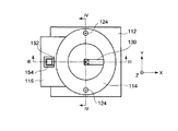
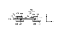
図1は、本発明の実施形態による走査型プローブ顕微鏡を示している。図2は、図1に示されたステージの平面図である。図3は、図2のIII−III線に沿ったステージの断面を示しており、これが図1に描かれている。図4は、図2のIV−IV線に沿ったステージの断面を示している。 FIG. 1 shows a scanning probe microscope according to an embodiment of the present invention. FIG. 2 is a plan view of the stage shown in FIG. FIG. 3 shows a cross section of the stage along the line III-III in FIG. 2, which is depicted in FIG. FIG. 4 shows a section of the stage along the line IV-IV in FIG.
続く説明においては、水平面に共に平行で互いに直交する二本の軸または二つの方向をそれぞれX軸・Y軸またはX方向・Y方向と呼び、水平面に直交する軸または方向をZ軸またはZ方向と呼ぶものとする。 In the following description, the two axes or two directions that are both parallel to the horizontal plane and orthogonal to each other are referred to as the X axis, the Y axis, or the X direction and the Y direction, respectively, and the axis or direction orthogonal to the horizontal plane is the Z axis or the Z direction. Shall be called.
原子間力顕微鏡100は、図1に示されるように、カンチレバー130と、水などの液体Lとカンチレバー130を保持するステージ110と、試料Sを保持する試料保持部164と、試料保持部164をX軸とY軸に沿って移動させる(XY走査する)とともにZ軸に沿って移動させる(Z走査する)XYZスキャナー162とを有している。
As shown in FIG. 1, the
カンチレバー130は、図3に示されるように、弾性変形可能な片持ち支持されたレバー部134と、レバー部134の自由端に支持された探針132とを備えている。
As shown in FIG. 3, the
ステージ110は、図1と図3に示されるように、液体Lを保持するガラス板116と、カンチレバー130を保持するカンチレバーホルダー114と、カンチレバーホルダー114を支持するステージベース112と、ガラス板116とカンチレバーホルダー114の間に配置された振動絶縁材120と、ガラス板116とステージベース112の間に配置された振動絶縁材122とを有している。
As shown in FIGS. 1 and 3, the
ガラス板116は、その表面が撥水処理されており、表面張力により液体Lを保持する。本明細書において、液体Lを保持するとは、液体Lを一個所に留めておくことを言う。
The
カンチレバーホルダー114とステージベース112は振動絶縁材120と122を介してガラス板116を保持している。振動絶縁材122と120は例えばゴム製や樹脂製のOリングで構成される。振動絶縁材122と120は好ましくはガラスと著しく異なる音響インピーダンスを有しているとよい。カンチレバーホルダー114は、図2に示されるように、二本のビス124によってステージベース112に固定されている。
The
図1に示されるように、試料保持部164に保持された試料Sは、ガラス板116に保持された液体Lの中に置かれる。またカンチレバー130は、試料Sに正対するように、ガラス板116に保持された液体Lの中に置かれる。
As shown in FIG. 1, the sample S held by the
原子間力顕微鏡100はさらに、カンチレバー130の自由端の変位を光学的に検出し、その変位を反映する変位信号を出力する変位検出センサー142と、変位検出センサー142からの変位信号に基づいてカンチレバー130の自由端の振動振幅を算出し、その振動振幅を反映する振幅信号を出力する振幅検出回路148とを有している。変位検出センサー142と振幅検出回路148は、カンチレバー130の自由端の振動を光学的に検出するための振動検出手段を構成している。
The
変位検出センサー142は例えば光てこセンサーで構成される。光てこセンサーの詳細は例えば特開2002−82037号に開示されている。しかし、変位検出センサー142は、光てこセンサーに限定されるものではなく、他のセンサーで構成されてもよい。 The displacement detection sensor 142 is constituted by an optical lever sensor, for example. Details of the optical lever sensor are disclosed in, for example, Japanese Patent Application Laid-Open No. 2002-82037. However, the displacement detection sensor 142 is not limited to the optical lever sensor, and may be composed of other sensors.
変位検出センサー142は、光ビームを発射する光源と、光源からの光ビームを収束してカンチレバー130の自由端に照射する対物レンズ144と、カンチレバー130からの反射光ビームを検出する光検出器とを含んでいる。対物レンズ144はガラス板116の下方に配置されている。
The displacement detection sensor 142 includes a light source that emits a light beam, an
光源から発射された光ビームBは対物レンズ144によって収束され、ガラス板116を通ってカンチレバー130の自由端に照射される。カンチレバー130で反射された光ビームはガラス板116を通って対物レンズ144に入射し、光検出器の受光面に光スポットを形成する。光スポットはカンチレバー130の自由端の変位に応じて光検出器の受光面上を移動する。光検出器は受光面上における光スポットの位置を反映した信号すなわちカンチレバー130の自由端の変位を反映した信号を出力する。
The light beam B emitted from the light source is converged by the
原子間力顕微鏡100はさらに、励振信号に従って振動を生成する振動子154と、振動子154によって生成された振動をガラス板116に伝達する振動伝達ブロック152とを備えている。振動子154と振動伝達ブロック152は、振動生成部を構成している。
The
振動子154は、これに限らないが、例えば圧電振動子で構成される。振動子154の周囲は好ましくはゴムや樹脂などの絶縁材により防水処理が施されているとよい。振動子154は振動伝達ブロック152に接着されている。ガラス板116は凹部118を有し、凹部118の底面はガラス板116の液体保持面(すなわち上面)に対して平行である。振動伝達ブロック152はガラス板116の凹部118の底面に取り付けられている。
For example, the
振動伝達ブロック152は、好ましくは、ガラス板116と等しい音響インピーダンスを有しているとよい。このため、振動伝達ブロック152は、ガラス材で構成されることが望ましいが、金属で構成されてもよい。
The
振動伝達ブロック152において、振動子154が接着される平面は、ガラス板116と接触する底面(平面)に対して、好ましくは30度〜60度の角度を成しているとよい。カンチレバー130の励振効率は低下するが、これ以外の角度、例えば0度(平行)であっても構わない。
In the
原子間力顕微鏡100はさらに、X走査信号に従ってXYZスキャナー162をX軸に沿って変位させるX駆動回路172と、Y走査信号に従ってXYZスキャナー162をY軸に沿って変位させるY駆動回路174と、Z制御信号に従ってXYZスキャナー162をZ軸に沿って変位させるZ駆動回路176とを有している。
The
原子間力顕微鏡100はコントローラー180を有している。コントローラー180は、X走査信号を生成するX走査信号生成部182と、Y走査信号を生成するY走査信号生成部184と、Z制御信号を生成するZ制御回路186と、励振信号を生成する励振信号生成部188とを含んでいる。Z制御回路186は、振幅検出回路146から入力される振幅信号を一定に保つようにXYZスキャナー162をZ方向に制御する回路であり、アナログ制御とデジタル制御(ソフトウエア制御)のどちらの方式であってもよい。
The
X走査信号は、XYZスキャナー162のX変位を指示する電気信号である。Y走査信号は、XYZスキャナー162のY変位を指示する電気信号である。Z制御信号は、入力される振幅信号を一定に保つための探針132と試料Sの間隔の目標値を示す電気信号(Zサーボ信号)である。励振信号は、振動子154を駆動するための電気信号であり、好ましくはカンチレバー130の機械的共振周波数近傍の周波数を有している。
The X scanning signal is an electric signal that instructs the X displacement of the
XYZスキャナー162とX走査信号生成部182とX駆動回路172とY走査信号生成部184とY駆動回路174は、試料保持部164をXY方向に走査するためのXY走査手段を構成している。またXYZスキャナー162とZ制御回路186とZ駆動回路176は、試料保持部164をZ方向に走査するためのZ走査手段を構成している。また、励振信号生成部188と振動子154と振動伝達ブロック152は、ガラス板116と液体Lを介してカンチレバー130を振動させるための励振手段を構成している。
The
また原子間力顕微鏡100はホストコンピューター190を有している。ホストコンピューター190は、試料情報を取得する情報取得手段であり、X走査信号とY走査信号とZ制御信号とに基づいて試料情報(たとえば試料Sの表面情報)を演算により取得する。また、ホストコンピューター190は画像や文字を表示する表示部を有しており、取得した試料情報を表示部に表示する。
Further, the
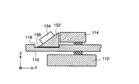
図5は、図3に示されたステージ断面の振動伝達ブロック周辺部を拡大して示している。図1と図2では図示が省略されていないが、図5に示されるように、振動伝達ブロック152はガラス板116の凹部118の底面に粘性材156を介して取り付けられている。粘性材156は、ゲル状またはグリース状の粘性が比較的高い物質である。
FIG. 5 shows an enlarged view of the periphery of the vibration transmission block in the section of the stage shown in FIG. Although not shown in FIGS. 1 and 2, the
振動子154によって振動伝達ブロック152内に生成された振動は振動伝達ブロック152からガラス板116に伝搬する。振動伝達ブロック152とガラス板116の凹部118の接触部分に空気層が存在すると振動の伝搬効率が悪くなる。粘性材156は空気層による振動の伝搬効率の低下を避けるために設けられている。
The vibration generated in the
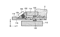
図6は、圧電素子が生成する振動が伝わる様子を示している。図6に示されるように、振動子154が接着される平面が凹部118の底面に対して30度〜60度の角度を成していると、振動は反射を繰り返してカンチレバー130へ効率良く伝わる。より詳しくは、ガラス板116と空気層は音響インピーダンスが著しく異なるので、振動は液体Lに届くまではガラス板116と空気層の界面でほぼ全反射される。ガラス板116と液体Lは音響インピーダンスが近いので、振動は液体Lに届いてからはガラス板116と液体Lの界面を半分程度が透過する。
FIG. 6 shows how the vibration generated by the piezoelectric element is transmitted. As shown in FIG. 6, when the plane to which the
また振動絶縁材122と120は好ましくはガラスと著しく異なる音響インピーダンスを有しているため、振動はガラス板116と振動絶縁材122と120の界面で効率良く反射される。また、ガラス板116と振動絶縁材122の界面を透過した振動は、振動絶縁材122によって減衰される(理想的には吸収される)ため、カンチレバーホルダー114をほとんど振動させない(理想的にはまったく振動させない)。
Further, since the
振動子154が接着される平面と凹部118の底面とが平行な場合でも、振動は複雑な反射を繰り返してカンチレバー130に伝わるが、その伝搬効率は極端に低下する。
Even when the plane to which the
本実施形態の原子間力顕微鏡100は次のように動作する。まず、コントローラー180内の励振信号生成部188から励振信号が出力され、振動子154に入力される。励振信号は所定の振幅を有し、カンチレバー130の機械的共振周波数と同じ周波数を有している。振動子154は励振信号の入力を受けて、カンチレバー130の機械的共振周波数と同じ周波数を持つ所定の振幅の振動を発生させる。振動子154で発生された振動は振動伝達ブロック152から粘性材156を介してガラス板116に伝搬し、ガラス板116から液体Lを介してカンチレバー130に伝搬し、カンチレバー130を所定の振幅・所定の周波数(カンチレバー130の機械的共振周波数近傍の周波数)で振動させる(励振する)。
The
この状態において、変位検出センサー142はカンチレバー130の自由端の変位を検出し、振幅検出回路148はカンチレバー130の自由端の振動の振幅を示す振幅信号を出力する。Z制御回路186は、振幅検出回路148から入力されるカンチレバー130の自由端の振幅信号に基づいて、カンチレバー130の自由端の振動振幅を一定値に保つためのZ制御信号を出力する。Z駆動回路176は、Z制御回路186から供給されるZ制御信号に従ってXYZスキャナー162を駆動して、XYZスキャナー162に保持された試料SのZ方向に移動させる。
In this state, the displacement detection sensor 142 detects the displacement of the free end of the
つまり、Z制御回路186とZ駆動回路176は共働して、XYZスキャナー162により、カンチレバー130に対する試料SのZ方向位置を制御する。Z制御回路186とZ駆動回路176は、最初、カンチレバー130の探針132と試料Sとが接触するまで、試料Sをカンチレバー130に接近させ、両者が接触した後は、カンチレバー130の自由端の振動振幅を一定に保つように、試料SのZ方向位置を制御する。
That is, the
このようなZ制御と並行して、X駆動回路172とY駆動回路174は、それぞれ、X走査信号生成部182とY走査信号生成部184から供給されるX走査信号とY走査信号に従ってXYZスキャナー162をX方向とY方向に駆動し、試料Sをカンチレバー130に対して二次元走査すなわちXY走査させる。
In parallel with such Z control, the
XY走査とZ制御の間、ホストコンピューター190は、X走査信号とY走査信号とZ制御信号とに基づいて試料情報、例えば試料Sの表面の凹凸情報を求めて表示したり、その情報に基づいて試料の表面の画像を形成して表示したりする。
During XY scanning and Z control, the
本実施形態の原子間力顕微鏡100では、カンチレバーホルダー114を機械的に振動させることなくカンチレバー130を励振することができる。これによりカンチレバー130を除いた部材の不所望な振動(カンチレバーホルダー114などの振動)が低減される。
In the
また、振動子154と振動伝達ブロック152とから成る構造体(振動生成部)はガラス板116から容易に取り外し可能である。これにより生体用原子間力顕微鏡において試料や試薬などの汚れが付きやすいカンチレバーホルダー114・ガラス板116・ステージベース112の洗浄が容易に行なえる。
Further, the structure (vibration generating unit) including the
これまで、図面を参照しながら本発明の実施形態を述べたが、本発明は、これらの実施形態に限定されるものではなく、その要旨を逸脱しない範囲において様々な変形や変更が施されてもよい。 The embodiments of the present invention have been described above with reference to the drawings. However, the present invention is not limited to these embodiments, and various modifications and changes can be made without departing from the scope of the present invention. Also good.
図7は、本発明の実施形態の変形例による振動伝達ブロック周辺部の断面図であり、図5に示されたガラス板と振動伝達ブロックに代えて適用可能な別のガラス板と振動伝達ブロックを示している。図7において、図5の部材と同一の参照符号で示された部材は同等の部材を示しており、それらの詳しい説明は記載の重複を避けて省略する。 FIG. 7 is a cross-sectional view of the periphery of a vibration transmission block according to a modification of the embodiment of the present invention. Another glass plate and vibration transmission block applicable in place of the glass plate and vibration transmission block shown in FIG. Is shown. In FIG. 7, members denoted by the same reference numerals as those in FIG. 5 indicate equivalent members, and detailed description thereof is omitted to avoid duplication of description.
本変形例では、図7に示されるように、ガラス板216は凹部218を有し、凹部218の底面はガラス板216の液体保持面(すなわち上面)に対して傾斜している。振動伝達ブロック252はガラス板216の凹部218の底面に粘性材156を介して取り付けられている。ガラス板216の凹部218の底面が傾斜しているため、振動伝達ブロック252はその自重によりXZ方向に拘束される。つまり振動伝達ブロック252が安定に保持される。
In the present modification, as shown in FIG. 7, the
100…原子間力顕微鏡、110…ステージ、112…ステージベース、114…カンチレバーホルダー、116…ガラス板、118…凹部、120…振動絶縁材、122…振動絶縁材、124…ビス、130…カンチレバー、132…探針、134…レバー部、142…変位検出センサー、144…対物レンズ、146…振幅検出回路、148…振幅検出回路、152…振動伝達ブロック、154…振動子、156…粘性材、162…XYZスキャナー、164…試料保持部、172…X駆動回路、174…Y駆動回路、176…Z駆動回路、180…コントローラー、182…X走査信号生成部、184…Y走査信号生成部、186…Z制御回路、188…励振信号生成部、190…ホストコンピューター、216…ガラス板、218…凹部、252…振動伝達ブロック。
DESCRIPTION OF
Claims (5)
試料を保持する試料保持部と、
自由端に探針を持つ弾性変形可能なカンチレバーと、
カンチレバーと液体を保持するステージとを備えており、ステージは、液体を保持するガラス板と、カンチレバーを保持するカンチレバーホルダーと、カンチレバーホルダーを支持するステージベースと、ガラス板とカンチレバーホルダーの間とガラス板とステージベースの間に配置された振動絶縁材とを有し、カンチレバーホルダーとステージベースは振動絶縁材を介してガラス板を保持しており、試料はガラス板に保持された液体の中に置かれ、カンチレバーは試料に正対するように液体の中に置かれ、さらに、
ガラス板に設けられ、ガラス板と液体を介してカンチレバーを振動させるための励振手段と、
試料保持部をXY方向に走査するためのXY走査手段と、
カンチレバーの自由端の振動を光学的に検出するための振動検出手段と、
XY走査手段・振動検出手段からの情報に基づいて試料情報を取得するための情報取得手段とを備えている、原子間力顕微鏡。 An atomic force microscope for observing a sample in a liquid;
A sample holder for holding the sample;
An elastically deformable cantilever with a probe at the free end;
The stage includes a cantilever and a stage for holding liquid. The stage includes a glass plate for holding the liquid, a cantilever holder for holding the cantilever, a stage base for supporting the cantilever holder, and between the glass plate and the cantilever holder. A vibration insulating material disposed between the plate and the stage base, the cantilever holder and the stage base hold the glass plate via the vibration insulating material, and the sample is contained in the liquid held on the glass plate. The cantilever is placed in the liquid so that it faces the sample, and
An excitation means provided on the glass plate for vibrating the cantilever through the glass plate and the liquid;
XY scanning means for scanning the sample holder in the XY direction;
Vibration detecting means for optically detecting vibration of the free end of the cantilever;
An atomic force microscope comprising: information acquisition means for acquiring sample information based on information from an XY scanning means and vibration detection means.
Priority Applications (1)
| Application Number | Priority Date | Filing Date | Title |
|---|---|---|---|
| JP2004342494A JP4391925B2 (en) | 2004-11-26 | 2004-11-26 | Atomic force microscope |
Applications Claiming Priority (1)
| Application Number | Priority Date | Filing Date | Title |
|---|---|---|---|
| JP2004342494A JP4391925B2 (en) | 2004-11-26 | 2004-11-26 | Atomic force microscope |
Publications (3)
| Publication Number | Publication Date |
|---|---|
| JP2006153574A JP2006153574A (en) | 2006-06-15 |
| JP2006153574A5 JP2006153574A5 (en) | 2007-11-29 |
| JP4391925B2 true JP4391925B2 (en) | 2009-12-24 |
Family
ID=36632074
Family Applications (1)
| Application Number | Title | Priority Date | Filing Date |
|---|---|---|---|
| JP2004342494A Expired - Fee Related JP4391925B2 (en) | 2004-11-26 | 2004-11-26 | Atomic force microscope |
Country Status (1)
| Country | Link |
|---|---|
| JP (1) | JP4391925B2 (en) |
Families Citing this family (9)
| Publication number | Priority date | Publication date | Assignee | Title |
|---|---|---|---|---|
| JP2008122325A (en) * | 2006-11-15 | 2008-05-29 | Jeol Ltd | Scanning probe microscope |
| JP2008134190A (en) | 2006-11-29 | 2008-06-12 | Olympus Corp | Cantilever holder and scanning probe microscope equipped therewith |
| JP4910949B2 (en) * | 2007-08-29 | 2012-04-04 | 株式会社島津製作所 | Method for analyzing samples in liquid |
| JP5185723B2 (en) * | 2008-08-01 | 2013-04-17 | オリンパス株式会社 | Atomic force microscope |
| KR101065981B1 (en) | 2009-05-20 | 2011-09-19 | 인하대학교 산학협력단 | Mechanically-coupled vibrating tuning fork-scanning probe system |
| US8505111B2 (en) | 2009-08-06 | 2013-08-06 | National University Corporation Kanazawa University | Cantilever excitation device and scanning probe microscope |
| KR101097768B1 (en) | 2009-11-30 | 2011-12-23 | 한국표준과학연구원 | Micro force sensor and micro force measurement method using double ended fork vibration |
| FR3054667B1 (en) * | 2016-07-26 | 2020-07-10 | Universite De Bourgogne | DEVICE FOR VOLUMETRIC ANALYSIS OF AN ORGANIC OR INORGANIC SAMPLE |
| WO2020044548A1 (en) * | 2018-08-31 | 2020-03-05 | オリンパス株式会社 | Atomic force microscope |
-
2004
- 2004-11-26 JP JP2004342494A patent/JP4391925B2/en not_active Expired - Fee Related
Also Published As
| Publication number | Publication date |
|---|---|
| JP2006153574A (en) | 2006-06-15 |
Similar Documents
| Publication | Publication Date | Title |
|---|---|---|
| US8322220B2 (en) | Non-destructive wafer-scale sub-surface ultrasonic microscopy employing near field AFM detection | |
| JP2730673B2 (en) | Method and apparatus for measuring physical properties using cantilever for introducing ultrasonic waves | |
| JP4688643B2 (en) | Excitation cantilever holder and scanning probe microscope | |
| US5481908A (en) | Resonance contact scanning force microscope | |
| JP2002107285A (en) | Magnetic force microscope | |
| JP4446929B2 (en) | Cantilever holder for scanning probe microscope and scanning probe microscope using the same | |
| JP4391925B2 (en) | Atomic force microscope | |
| JP4474556B2 (en) | Scanning probe microscope | |
| JP4816414B2 (en) | Scanning probe microscope | |
| JP2004198427A (en) | Probe device | |
| US5681987A (en) | Resonance contact scanning force microscope | |
| JP2000146804A (en) | Method for determining distance between near-field probe and sample surface to be inspected and near-field microscope | |
| JP5585965B2 (en) | Cantilever excitation device and scanning probe microscope | |
| JP2004156958A (en) | Scanning probe microscope | |
| JPH0792464B2 (en) | Ultrasonic vibration detection method in atomic force microscope and sample observation method in atomic force microscope | |
| JP2004156959A (en) | Scanning probe microscope | |
| JPH10267950A (en) | Lateral-excitation frictional-force microscope | |
| JPH10160742A (en) | Sample holder of scanning probe microscope | |
| JP7531919B2 (en) | Scanning probe microscope and drive control device for scanning probe microscope | |
| JP2010190590A (en) | Scanning probe microscope and method of operating the same | |
| JPH07174767A (en) | Scanning type probe microscope | |
| JP3859275B2 (en) | Scanning probe microscope | |
| JP2005188967A (en) | Scanning probe microscope | |
| JP2006349419A (en) | Three-dimensional sample observation system and three-dimensional sample observation method | |
| JP2002082037A (en) | Optical-lever type optical system for interatomic force microscope |
Legal Events
| Date | Code | Title | Description |
|---|---|---|---|
| A521 | Request for written amendment filed |
Free format text: JAPANESE INTERMEDIATE CODE: A523 Effective date: 20071017 |
|
| A621 | Written request for application examination |
Free format text: JAPANESE INTERMEDIATE CODE: A621 Effective date: 20071017 |
|
| A977 | Report on retrieval |
Free format text: JAPANESE INTERMEDIATE CODE: A971007 Effective date: 20090713 |
|
| TRDD | Decision of grant or rejection written | ||
| A01 | Written decision to grant a patent or to grant a registration (utility model) |
Free format text: JAPANESE INTERMEDIATE CODE: A01 Effective date: 20090915 |
|
| A01 | Written decision to grant a patent or to grant a registration (utility model) |
Free format text: JAPANESE INTERMEDIATE CODE: A01 |
|
| A61 | First payment of annual fees (during grant procedure) |
Free format text: JAPANESE INTERMEDIATE CODE: A61 Effective date: 20091008 |
|
| FPAY | Renewal fee payment (event date is renewal date of database) |
Free format text: PAYMENT UNTIL: 20121016 Year of fee payment: 3 |
|
| R151 | Written notification of patent or utility model registration |
Ref document number: 4391925 Country of ref document: JP Free format text: JAPANESE INTERMEDIATE CODE: R151 |
|
| FPAY | Renewal fee payment (event date is renewal date of database) |
Free format text: PAYMENT UNTIL: 20121016 Year of fee payment: 3 |
|
| FPAY | Renewal fee payment (event date is renewal date of database) |
Free format text: PAYMENT UNTIL: 20131016 Year of fee payment: 4 |
|
| S531 | Written request for registration of change of domicile |
Free format text: JAPANESE INTERMEDIATE CODE: R313531 |
|
| R350 | Written notification of registration of transfer |
Free format text: JAPANESE INTERMEDIATE CODE: R350 |
|
| R250 | Receipt of annual fees |
Free format text: JAPANESE INTERMEDIATE CODE: R250 |
|
| R250 | Receipt of annual fees |
Free format text: JAPANESE INTERMEDIATE CODE: R250 |
|
| R250 | Receipt of annual fees |
Free format text: JAPANESE INTERMEDIATE CODE: R250 |
|
| R250 | Receipt of annual fees |
Free format text: JAPANESE INTERMEDIATE CODE: R250 |
|
| R250 | Receipt of annual fees |
Free format text: JAPANESE INTERMEDIATE CODE: R250 |
|
| LAPS | Cancellation because of no payment of annual fees |


