JP4385666B2 - Recording medium cutting device and recording device - Google Patents
Recording medium cutting device and recording device Download PDFInfo
- Publication number
- JP4385666B2 JP4385666B2 JP2003195514A JP2003195514A JP4385666B2 JP 4385666 B2 JP4385666 B2 JP 4385666B2 JP 2003195514 A JP2003195514 A JP 2003195514A JP 2003195514 A JP2003195514 A JP 2003195514A JP 4385666 B2 JP4385666 B2 JP 4385666B2
- Authority
- JP
- Japan
- Prior art keywords
- cutting
- roll paper
- scanning direction
- roller
- recording
- Prior art date
- Legal status (The legal status is an assumption and is not a legal conclusion. Google has not performed a legal analysis and makes no representation as to the accuracy of the status listed.)
- Expired - Fee Related
Links
Images


Landscapes
- Handling Of Sheets (AREA)
- Handling Of Continuous Sheets Of Paper (AREA)
- Nonmetal Cutting Devices (AREA)
Description
【0001】
【発明の属する技術分野】
本発明は、搬送され記録された記録媒体の記録部分を搬送方向及びそれの直交方向に切断する切断手段を備えた記録媒体切断装置及びその記録媒体切断装置を備えた記録装置に関する。
【0002】
【従来の技術】
従来の記録装置の1つであるプリンタには、媒体であるロール紙をカッティングするカッタを備えたものがある。このプリンタは、ロール紙を副走査方向(搬送方向)に搬送しつつ記録ヘッドを主走査方向(搬送直交方向)に移動させて、複数の画像を副走査方向に1枚ずつ並べて記録した後、カッタを主走査方向に移動させて複数の画像が記録されたロール紙を一纏めにカッティングするようになっている。
【0003】
このようなプリンタが例えばJIS規格のA1判やJIS規格のB1判といった比較的大型のサイズの用紙幅を有するロール紙に記録できる大型のプリンタであって、複数の画像が例えばJIS規格のA5判やJIS規格のB6判といった比較的小型なサイズのときは、複数の画像をロール紙の幅方向に並べて記録することも可能である。このような記録方法を採ることにより、記録処理時間を短縮させることができるとともに、ロール紙の使用効率を向上させることができる(特許文献1参照)。
【0004】
【特許文献1】
特開平2000−158738号公報
【0005】
【発明が解決しようとする課題】
上述した従来の大型のプリンタは、カッタを主走査方向に移動させてロール紙を幅方向にカッティングするのみであるため、ロール紙の幅方向に複数の画像が記録されていても、個々の画像に切り分けることができない。このため、後で手作業により個々の画像に切り分ける必要がある。
【0006】
本発明は、上記のような種々の課題に鑑みなされたものであり、その目的は、記録媒体の搬送方向及び搬送直交方向に複数記録された画像を自動的に個々に切断することができる記録媒体切断装置及びその記録媒体切断装置を備えた記録装置を提供することにある。
【0007】
【課題を解決するための手段】
上記目的達成のため、本発明の記録媒体切断装置では、搬送され記録された記録媒体の記録部分を搬送方向及び搬送直交方向に切断する切断手段を備えた記録媒体切断装置であって、前記切断手段は、搬送方向及び搬送直交方向に複数記録された画像のうち、前記記録媒体の一側端側に近い位置に記録された画像から順に搬送方向の切断を行った後、前記記録媒体の搬送先端側に近い位置に記録された画像から順に搬送直交方向の切断を行うことを特徴としている。これにより、複数の画像を記録媒体に自由な寸法や配置で記録しても、各画像を自動的に切り分けることができるので、従来のようにユーザが切断処理する必要は無く、切断精度の高い各画像を容易に得ることができる。
【0008】
また、前記切断手段は、搬送直交方向に移動自在であり、搬送直交方向の所定位置で停止した状態で前記記録媒体を逆搬送させることにより搬送方向の切断を行うことを特徴としている。これにより、記録媒体を引っ張った状態で切断することができるので、切断精度を高めることができる。また、前記切断手段は、搬送直交方向に移動自在であり、前記記録媒体を所定位置で停止させた状態で搬送直交方向に移動することにより搬送直交方向の切断を行うことを特徴としている。これにより、例えば切断手段を記録ヘッドが搭載されたキャリッジに装着して移動させることができるので、切断手段のための移動手段を新たに配設する必要が無く、コストを低減させることができるとともに、装置をコンパクトに構成することができる。
【0009】
上記目的達成のため、本発明の記録装置では、記録媒体に記録して当該記録部分を切断する記録装置であって、上記各記録媒体切断装置を備えたことを特徴としている。これにより、上記各記録媒体切断装置の作用を奏する記録装置を提供することができる。
【0010】
【発明の実施の形態】
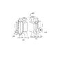
図1は、本発明の実施の形態に係る記録媒体切断装置が適用された記録装置の1つであるインクジェット式プリンタの構成例を示す斜視図であり、図2は、そのインクジェット式プリンタの主要部の内部構成例を示す斜視図、図3は、その断面図である。図1〜図3に示すインクジェット式プリンタ100は、例えばJIS規格のA1判やJIS規格のB1判といった比較的大型のサイズの用紙幅を有するロール紙に記録できる大型のプリンタである。このインクジェット式プリンタ100は、本体部110内に記録部120と排紙部130と本実施形態に係る記録媒体切断装置200が配設され、本体部110を支える脚部140の間に給紙部150が配設された構成となっている。
【0011】
本体部110は、図1〜図3に示すように、記録部120と排紙部130を覆うプラスチックあるいは板金でなるハウジング111を備えている。そして、このハウジング111は、図1〜図3に示すように、上面及び前面が開放可能なように半透明もしくは透明のプラスチックあるいは板金でなる上蓋112及び前蓋113が配設されている。
【0012】
上蓋112は、図1〜図3に示すように、後部が回動可能に支持されており、ユーザが前部を持って押し上げ、あるいは押し下げることにより開閉するようになっている。ユーザは、上蓋112を開けることにより記録部120及び排紙部130の上方を大きく開放することができるので、記録ヘッド121やキャリッジ122等のメンテナンス作業及び記録中や排紙中における紙ジャム等の用紙搬送エラーの解除作業等を容易に行うことができる。
【0013】
前蓋113は、図1〜図3に示すように、下部が回動可能に支持されており、ユーザが上部を持って押し下げ、あるいは押し上げることにより開閉するようになっている。ユーザは、前蓋113を開けることにより記録部120及び排紙部130の下方を大きく開放することができるので、給紙中における紙ジャム等の用紙搬送エラーの解除作業等を容易に行うことができる。
【0014】
また、本体110の前面側から見て右側下部には、図1及び図2に示すように、各色のインクカートリッジ10を収納保持するホルダ本体161とその前面を覆うカバー162を有するインクカートリッジホルダ160が配設されている。このカバー162は、下部がホルダ本体161に対し回動可能に支持されており、ユーザが上部を持って押し下げ、あるいは押し上げることにより開閉するようになっている。ユーザは、カバー162を開けることによりホルダ本体161を大きく開放することができるので、インクカートリッジ10の交換作業等を容易に行うことができる。
【0015】
さらに、本体110の前面側から見て右側上部には、図1及び図2に示すように、ユーザが記録制御等を操作するための操作パネル170が配設されている。この操作パネル170は、液晶画面と各種ボタンが配設されており、ユーザが液晶画面を見て確認しながらボタン操作できるようになっている。ユーザは、視認による確実な操作を行うことができるので、動作エラーや動作ミス等を無くすことができる。
【0016】
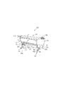
記録部120は、図2及び図3に示すように、記録ヘッド121を搭載したキャリッジ122、記録ヘッド121と記録を実行するための図示しない制御部とを電気的に接続するフレキシブルフラットケーブル(以下、FFCという)123、記録ヘッド121とインクが入ったインクカートリッジ10とをつなぐインクチューブ124、ロール紙を搬送する紙送りローラ125とその従動ローラ126、ロール紙の浮き上がりを防止する図示しない紙吸引手段等を備えている。
【0017】
記録ヘッド121は、ブラックインクを吐出するブラックインク用記録ヘッドと、ダークイエロー、イエロー、ライトシアン、シアン、ライトマゼンタ、マゼンタ等の各色のインクを吐出する複数のカラーインク用記録ヘッドとを備えている。そして、記録ヘッド121は、圧力発生室とそれに繋がるノズル開口が設けられており、圧力発生室内にインクを貯留して所定圧で加圧することにより、ノズル開口からロール紙に向けてコントロールされた大きさのインク滴を吐出するようになっている。
【0018】
キャリッジ122は、図2に示すように、主走査方向に設けられているレール127にベアリングを介して載置され、キャリッジベルト128に連結されており、図示しないキャリッジ駆動装置によってキャリッジベルト128が作動すると、キャリッジベルト128の動きに連行され、レール127に案内されて往復移動するようになっている。FFC123は、一端が制御部のコネクタに接続され、他端が記録ヘッド121のコネクタに接続されており、記録信号を制御部から記録ヘッド121に送るようになっている。
【0019】
インクチューブ124は、上記各色のインク用が配設されており、図示しないインク加圧供給手段を介して各一端が対応する各色のインクカートリッジ10に繋がれ、各他端が対応する各色の記録ヘッド121に繋がれている。そして、インクチューブ124は、インク加圧供給手段によって加圧された各色のインクをインクカートリッジ10から記録ヘッド121に送るようになっている。
【0020】
紙送りローラ125は、図示しないモータから伝達される駆動力により正逆回転駆動するようになっている。従動ローラ126は、バネ等の付勢部材により紙送りローラ125に押圧されており、紙送りローラ125の正逆回転駆動に追従して正逆回転するようになっている。そして、紙送りローラ125とその従動ローラ126は、給紙されるロール紙を挟持して送り出すようになっている。
【0021】
排紙部130は、図2及び図3に示すように、ロール紙を副走査方向に搬送して排紙する排紙ローラ131とその従動ローラ132等を備えている。排紙ローラ131は、モータから紙送りローラ125を介して伝達される駆動力により正逆回転駆動するようになっている。従動ローラ132は、バネ等の付勢部材により排紙ローラ131に押圧されており、排紙ローラ131の正回転駆動に追従して正回転するようになっている。排紙ローラ131とその従動ローラ132は、搬送されるロール紙を挟持して送り出すようになっている。
【0022】
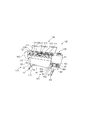
記録媒体切断装置200は、図3に示すように、ロール紙の記録部分を主走査方向にカッティングする横カット用カッタユニット(切断手段)210、この横カット用カッタユニット210の片側に並設され、主走査方向のカッティング時にロール紙を押える押えローラ220を備えている。さらに、ロール紙の記録部分を副走査方向にカッティングする縦カット用カッタユニット(切断手段)230、この縦カット用カッタユニット230の片側に並設され、副走査方向のカッティング時にロール紙を押える押えローラ240等を備えている。このような構成の記録媒体切断装置200の第1の実施形態の詳細について、図4を参照して説明する。
【0023】
図4は、上記記録媒体切断装置200の第1の実施形態の詳細を示す斜視図である。横カット用カッタユニット210は、両刃の横カット用カッタ211、この横カット用カッタ211が下端に取り付けられているとともに、押えローラ220が横カット用カッタ211のプリンタ前面から見て手前側に並ぶようにして取り付けられたホルダ212等を備えている。ホルダ212は、横カット用カッタ211の刃先が下方を向いた状態で、押えローラ220とともに上下方向及び主走査方向に移動自在に配設されている。なお、横カット用カッタ211として両刃を使用したが、片刃でも良い。
【0024】
横カット用カッタ211及び押えローラ220を上下方向に移動させる手段としては、例えばソレノイドコイル、エアシリンダ、油圧シリンダ、モータとギア機構もしくはプーリ機構の組合せ等が用いられる。また、横カット用カッタ211及び押えローラ220を主走査方向へ移動させる手段としては、例えばモータとプーリ機構の組合せ等が用いられるが、キャリッジ122に直接取り付けるようにしても良い。
【0025】
縦カット用カッタユニット230は、片刃の縦カット用カッタ231、この縦カット用カッタ231が下端に取り付けられているとともに、押えローラ240が縦カット用カッタ231のプリンタ前面から見て左側に並ぶようにして取り付けられたホルダ232等を備えている。ホルダ232は、縦カット用カッタ231の刃先が下方を向いた状態で、押えローラ240とともに上下方向及び主走査方向に移動自在に配設されている。なお、縦カット用カッタ231として片刃を使用したが、両刃でも良い。
【0026】
縦カット用カッタ231及び押えローラ240を上下方向に移動させる手段としては、例えばソレノイドコイル、エアシリンダ、油圧シリンダ、モータとギア機構もしくはプーリ機構の組合せ等が用いられる。また、縦カット用カッタ231及び押えローラ240を主走査方向へ移動させる手段としては、例えばモータとプーリ機構の組合せ等が用いられるが、キャリッジ122に直接取り付けるようにしても良い。
【0027】
このような横カット用カッタユニット210及びローラ220と、縦カット用カッタユニット230及び押えローラ240は、別体で構成しても良く、一体で構成しても良い。別体で構成することにより、例えば横カット用カッタユニット210及びローラ220がカッティング動作している間に縦カット用カッタユニット230及び押えローラ240を移動動作させることができるので、カッティング処理時間を短縮させることができる。また、一体で構成することにより、横カット用カッタユニット210及びローラ220と、縦カット用カッタユニット230及び押えローラ240を主走査方向に移動させる手段を共有させることができる。
【0028】
図5は、上記記録媒体切断装置200によるロール紙Rのカッティング方法を示す図である。このロール紙Rには、ロール紙Rの搬送先端側から見て主走査方向右側に画像P1が記録され、その主走査方向左側に画像P1より縦横の寸法が小さい画像P2が主走査方向に隙間を空けて、すなわち画像P1と離間して記録されている。さらに、画像P1の主走査方向左側であって画像P2の副走査方向後側に画像P2より縦横の寸法が小さい画像P3が主走査方向及び副走査方向に隙間を空けて、すなわち画像P1及び画像P2と離間して記録されている。なお、画像P1の副走査方向前側と画像P2の副走査方向前側は同一直線上に記録され、画像P2の主走査方向右側と画像P3の主走査方向右側は同一直線上に記録されている。
【0029】
このようなロール紙Rの各画像P1〜P3をカッティングする際は、先ず、図5(A)に示すように、縦カット用カッタ231が、記録済みのロール紙Rの記録部分である画像P1〜画像P3のうち一側端側に近い位置に記録された画像から順に搬送方向、すなわち副走査方向にカッティングする。次に、図5(B)に示すように、横カット用カッタ211が、上記記録部分である画像P1〜画像P3のうち搬送先端側に近い位置に記録された画像から順に搬送直交方向、すなわち主走査方向にカッティングする。
【0030】
すなわち、先ず、図5(A)に示すように、縦カット用カッタ231が上昇した状態で主走査方向に移動するとともに、ロール紙Rが逆搬送される。そして、縦カット用カッタ231が、ロール紙Rの搬送先端側から見て右側端側に近い位置に記録された画像P1の主走査方向右側▲1▼の後方頂点に位置決めされて下降した後、ロール紙Rが逆搬送されて画像P1の主走査方向右側▲1▼をカッティングする。次に、縦カット用カッタ231が上昇して主走査方向に移動するとともに、ロール紙Rが搬送される。そして、縦カット用カッタ231が、画像P1の主走査方向左側▲2▼の後方頂点に位置決めされて下降した後、ロール紙Rが逆搬送されて画像P1の主走査方向左側▲2▼をカッティングする。
【0031】
次に、縦カット用カッタ231が上昇して主走査方向に移動するとともに、ロール紙Rが搬送される。そして、縦カット用カッタ231が、画像P3の主走査方向右側▲3▼の後方頂点に位置決めされて下降した後、ロール紙Rが逆搬送されて画像P3の主走査方向右側▲3▼をカッティングする。さらに、縦カット用カッタ231が上昇してロール紙Rが逆搬送される。そして、縦カット用カッタ231が、画像P2の主走査方向右側▲4▼の後方頂点に位置決めされて下降した後、ロール紙Rが逆搬送されて画像P2の主走査方向右側▲4▼をカッティングする。この場合のカッティング順序としては、画像P2の主走査方向右側▲4▼をカッティングした後で画像P3の主走査方向右側▲3▼をカッティングするようにしても良い。
【0032】
次に、縦カット用カッタ231が上昇して主走査方向に移動するとともに、ロール紙Rが搬送される。そして、縦カット用カッタ231が、画像P3の主走査方向左側▲5▼の後方頂点に位置決めされて下降した後、ロール紙Rが逆搬送されて画像P3の主走査方向左側▲5▼をカッティングする。さらに、縦カット用カッタ231が上昇して主走査方向に移動するとともに、ロール紙Rが逆搬送される。そして、縦カット用カッタ231が、画像P2の主走査方向左側▲6▼の後方頂点に位置決めされて下降した後、ロール紙Rが逆搬送されて画像P2の主走査方向左側▲6▼をカッティングする。以上により、全画像P1〜P3の搬送方向のカッティングが完了する。なお、ロール紙Rの搬送先端側から見て右側端側に近い位置に記録された画像P1からカッティングするようにしたが、ロール紙Rの搬送先端側から見て左側端側に近い位置に記録された画像P2からカッティングするようにしても良い。
【0033】
続いて、図5(B)に示すように、横カット用カッタ211が、上昇した状態で主走査方向に移動し、ロール紙Rの搬送先端側に近い位置に記録された画像P2の副走査方向前側▲1▼の左方頂点に位置決めされて下降した後、主走査方向に移動して画像P2の副走査方向前側▲1▼をカッティングする。さらに、横カット用カッタ211が、上昇して主走査方向に移動し、画像P1の副走査方向前側▲2▼の左方頂点に位置決めされて下降した後、主走査方向に移動して画像P2の副走査方向前側▲2▼をカッティングする。
【0034】
次に、横カット用カッタ211が上昇して主走査方向に移動するとともに、ロール紙Rが搬送される。そして、横カット用カッタ211が、画像P2の副走査方向後側▲3▼の右方頂点に位置決めされて下降した後、主走査方向に移動して画像P2の副走査方向後側▲3▼をカッティングする。さらに、横カット用カッタ211が上昇して主走査方向に移動するとともに、ロール紙Rが搬送される。そして、横カット用カッタ211が、画像P3の副走査方向前側▲4▼の左方頂点に位置決めされて下降した後、主走査方向に移動して画像P3の副走査方向前側▲4▼をカッティングする。
【0035】
次に、横カット用カッタ211が上昇して主走査方向に移動するとともに、ロール紙Rが搬送される。そして、横カット用カッタ211が、画像P1の副走査方向後側▲5▼の左方頂点に位置決めされて下降した後、主走査方向に移動して画像P1の副走査方向後側▲5▼をカッティングする。さらに、横カット用カッタ211が上昇して主走査方向に移動するとともに、ロール紙Rが搬送される。そして、横カット用カッタ211が、画像P3の副走査方向後側▲6▼の右方頂点に位置決めされて下降した後、主走査方向に移動して画像P3の副走査方向後側▲6▼をカッティングする。以上により、全画像P1〜P3の搬送直交方向のカッティングが完了する。なお、全画像P1〜P3の搬送直交方向のカッティングは、上記カッティング方向とは逆方向にカッティングするようにしても良い。
【0036】
各画像P1〜P3の主走査方向のカッティングラインは搬送直交方向に延びているので、ロール紙Rを搬送したり逆搬送する際にカッティング端面がインクジェット式プリンタ100内の突起や段差等に引っ掛かるおそれがある。一方、各画像P1〜P3の副走査方向のカッティングラインは搬送方向に延びているので、ロール紙Rを搬送したり逆搬送してもカッティング端面がインクジェット式プリンタ100内の突起や段差等に引っ掛かることは無い。
【0037】
そこで、先に各画像P1〜P3の副走査方向のカッティングを行うようにして、カッティング端面がインクジェット式プリンタ100内の突起や段差等に引っ掛からないようにしている。また、後で行う各画像P1〜P3の主走査方向のカッティング後は、カッティング端面を搬送方向にのみ送って逆搬送方向には戻さないようにするとともに、カッティングから排紙までの短い搬送経路上には突起や段差等を配設しないようにして、カッティング端面がインクジェット式プリンタ100内の突起や段差等に引っ掛からないようにしている。これにより、ロール紙Rの傷付きを防止することができるので、記録精度やカッティング精度を高精度に保つことができるとともに、従来のようにユーザが後で手作業により個々の画像に切り分ける必要が無くなるので、ユーザの手間を軽減することができる。
【0038】
図6は、上記記録媒体切断装置200の第2の実施形態の詳細を示す斜視図であり、図4と同一構成箇所は同一番号を付してある。横カット用カッタユニット210は、両刃の横カット用カッタ213、この横カット用カッタ213が下端に取り付けられているとともに、押えローラ220が横カット用カッタ213と並ぶようにして取り付けられたスライダ214、このスライダ214が上下に摺動自在に収納されたケース215、スライダ214をケース215内で上下に摺動させるソレノイドコイル216等を備えている。
【0039】
ソレノイドコイル216は、スライダ214をケース215内で上下動させ、横カット用カッタ213を刃先が下方を向いた状態でケース215に対し出し入れするようになっている。横カット用カッタ213及び押えローラ220を上下方向に移動させる手段としては、ソレノイドコイル216の他に、例えばエアシリンダ、油圧シリンダ、モータとギア機構もしくはプーリ機構の組合せ等を用いても良い。また、横カット用カッタユニット210及び押えローラ220は、主走査方向に移動自在に配設されている。横カット用カッタユニット210及び押えローラ220を主走査方向へ移動させる手段としては、例えばモータとプーリ機構の組合せ等が用いられるが、キャリッジ122に直接取り付けるようにしても良い。なお、横カット用カッタ213として両刃を使用したが、片刃でも良い。
【0040】
縦カット用カッタユニット230は、片刃の縦カット用カッタ233、この縦カット用カッタ233が下端に取り付けられているとともに、押えローラ240が横カット用カッタ233と並ぶようにして取り付けられたスライダ234、このスライダ234が上下に摺動自在に収納されたケース235、スライダ234をケース235内で上下に摺動させるソレノイドコイル236等を備えている。
【0041】
ソレノイドコイル236は、スライダ234をケース235内で上下動させ、縦カット用カッタ233を刃先が下方を向いた状態でケース235に対し出し入れするようになっている。縦カット用カッタ233及び押えローラ240を上下方向に移動させる手段としては、ソレノイドコイル236の他に、例えばエアシリンダ、油圧シリンダ、モータとギア機構もしくはプーリ機構の組合せ等を用いても良い。また、縦カット用カッタユニット230及び押えローラ240は、主走査方向に移動自在に配設されている。縦カット用カッタユニット230及び押えローラ240を主走査方向へ移動させる手段としては、例えばモータとプーリ機構の組合せ等が用いられるが、キャリッジ122に直接取り付けるようにしても良い。なお、縦カット用カッタ233として片刃を使用したが、両刃でも良い。
【0042】
このような横カット用カッタユニット210及びローラ220と、縦カット用カッタユニット230及び押えローラ240は、別体で構成されており、別体で構成することにより、例えば横カット用カッタユニット210及びローラ220がカッティング動作している間に縦カット用カッタユニット230及び押えローラ240を移動動作させることができるので、カッティング処理時間を短縮させることができる。このような構成の記録媒体切断装置200であっても、図5に示すようなロール紙Rに記録された画像を図4の記録媒体切断装置200と同様の作用効果を持ってカッティングすることができる。
【0043】
図7は、上記記録媒体切断装置200の第3の実施形態の詳細を示す斜視図である。この記録媒体切断装置250は、カッティング方向が主走査方向及び副走査方向に方向変換可能なように構成されている。すなわち、ロール紙の記録部分を主走査方向及び副走査方向にカッティングする片刃のカッタ(切断手段)251、このカッタ251が下端に取り付けられているホルダ(切断手段)252、カッタ251と並ぶようにしてホルダ252に取り付けられ、主走査方向及び副走査方向のカッティング時にロール紙を押える押えローラ253を備えている。
【0044】
さらに、ホルダ252をカッタ251及び押えローラ253とともに90度回転させるモータ(切断手段)254及びギア機構(切断手段)255、ホルダ252をカッタ251、押えローラ253、モータ254及びギア機構255とともに上下動させるソレノイドコイル(切断手段)256等を備えている。ホルダ252をカッタ251、押えローラ253、モータ254及びギア機構255とともに上下方向に移動させる手段としては、ソレノイドコイル256の他に、例えばエアシリンダ、油圧シリンダ、モータとギア機構もしくはプーリ機構の組合せ等を用いても良い。
【0045】
また、記録媒体切断装置250は、主走査方向に移動自在に配設されている。記録媒体切断装置250を主走査方向へ移動させる手段としては、例えばモータとプーリ機構の組合せ等が用いられるが、キャリッジ122に直接取り付けるようにしても良い。なお、カッタ251として片刃を使用したが、両刃でも良い。このカッタ251は1つで済むので、カッタ251の交換作業が容易となる。このような構成の記録媒体切断装置250であっても、図5に示すようなロール紙Rに記録された画像を図4の記録媒体切断装置200と同様の作用効果を持ってカッティングすることができる。
【0046】
脚部140は、図1及び図2に示すように、移動用のコロ141を有する2本の支持柱142を備えている。そして、支持柱142の上部に本体部110が載置されネジ止め固定されるようになっている。支持柱142に移動用のコロ141が配設されていることにより、重量のある本体部110を所望の位置へスムーズに移動させて設置することができるようになっている。
【0047】
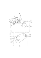
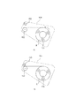
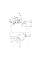
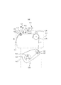
給紙部150は、図1及び図3に示すように、本体部110の下方であって脚部140の間に配設されており、ロール紙の両端を支持する一対の支持部151、ロール紙を給送する送り出しローラ152とピンチローラ153を備えている。さらに、支持部151が固定されているとともに、送り出しローラ152とピンチローラ153の各両端が軸支されている一対のアーム部154を備えている。このような構成の給紙部150の詳細について、さらに図8を参照して以下説明する。
【0048】
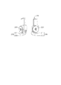
図8は、上記給紙部150の詳細を示す斜視図である。一対の支持部151は、対向配置される一対のアーム部154の対向面にそれぞれ固定して取り付けられている。そして、一対の支持部151は、軸受が内蔵されており、図9に示すロール紙Rの内周部に貫装されてロール紙Rを支持するスピンドル155の両端を回動自在に軸支持するようになっている。
【0049】
すなわち、スピンドル155は、中央にロール紙Rが嵌め込まれてロール紙Rの両側に一対のフランジ状のロール紙押さえ156が嵌め込まれ、一対の支持部151の間に架け渡されるようになっている。ユーザは、スピンドル155が取り付けられたロール紙を持ち上げて、スピンドル155の両端を一対の支持部151に嵌め込むのみでロール紙の装着を完了させることができるので、ロール紙のセッティング作業工数を大幅に減少させることができる。
【0050】
送り出しローラ152とピンチローラ153は、各両端が対向配置される一対のアーム部154の対向面にそれぞれ回動自在に軸支持されている。すなわち、送り出しローラ152とピンチローラ153は、一対のアーム部154の間に架け渡されるようにして配設されている。そして、送り出しローラ152の両端は一対のアーム部154の対向面の一定箇所に軸支持されているが、ピンチローラ153は送り出しローラ152に対して当接・離間可能なように、ピンチローラ153の両端軸は一対のアーム部154の対向面に設けられた例えば溝内を移動可能に軸支持されている。そして、ピンチローラ153は、送り出しローラ152に対して当接した位置及び離間した位置にて、例えばアーム部154の対向面に設けられた係止部材と付勢部材等を用いたロック機構によりロックされるようになっている。
【0051】
ユーザは、支持部151に内蔵されている軸受により、ロール紙の先端部を容易に引き出すことができるとともに、ピンチローラ153の移動機構により、ロール紙の先端部を送り出しローラ152とピンチローラ153の間に容易に挿入・挟持させることができるので、ロール紙のセッティング作業工数を大幅に減少させることができる。
【0052】
一対のアーム部154は、脚部140の2本の支持柱142の対向面にそれぞれ図示矢印方向に回動自在に取り付けられている。そして、一対のアーム部154の回動は、図10に示すロール紙のセッティング位置と図8に示すロール紙の給紙位置にて、例えば支持柱142の対向面に設けられた係止部材と付勢部材等を用いたロック機構によりロックされて位置決めされるようになっている。
【0053】
すなわち、一対のアーム部154をロール紙のセッティング位置に回動させたときは、送り出しローラ152とピンチローラ153はインクジェット式プリンタ100の前面側に飛び出し、一対のアーム部154をロール紙の給紙位置に回動させたときは、送り出しローラ152とピンチローラ153はインクジェット式プリンタ100の背面側に回り込んで、ロール紙の搬送経路と接続されるようになっている。
【0054】
ユーザは、ロール紙の先端部を送り出しローラ152とピンチローラ153の間に挿入・挟持させる際、インクジェット式プリンタ100の背面側に潜り込まなくても、インクジェット式プリンタ100の前面側にて通常の立ち位置で作業を行うことができるので、ロール紙のセッティング作業工数を大幅に減少させることができる。
【0055】
なお、上述した実施形態では、一対の支持部151は、対向配置される一対のアーム部154の対向面にそれぞれ固定して取り付けられ、アーム部154とともに回動する構成としたが、脚部140の2本の支持柱142の対向面に取り付けられたアーム部154の回動軸と同芯の軸にそれぞれ固定して取り付けるように構成しても同様の効果を奏する。すなわち、アーム部154の回動とは無関係に常に一定位置に固定された支持部151としても良い。
【0056】
このような構成において、第1の実施形態の記録媒体切断装置200を備えたインクジェット式プリンタ100の使用手順を図9〜図15を参照して説明する。先ず、図9(A)に示すように、ユーザは、スピンドル155に嵌め込まれている一対のロール紙押さえ156の一方をスピンドル155の一端から引き抜く。そして、図9(B)に示すように、ユーザは、スピンドル155の一端をロール紙Rの軸穴Cの一端から挿入して貫通させる。
【0057】
さらに、ユーザは、図9(C)に示すように、ロール紙Rの軸穴Cの一端をスピンドル155の他端側に挿入固定されている他方のロール紙押さえ156に嵌め込んで当接させる。続いて、ユーザは、一方のロール紙押さえ156をスピンドル155の一端から挿入して、ロール紙Rの軸穴Cの他端に嵌め込む。これにより、ロール紙Rはスピンドル155と共に回転可能となる。
【0058】
次に、ユーザは、例えば送り出しローラ152を手前に引いてアーム部154を揺動させ、ロール紙の給紙位置に位置決めされている状態(図8参照)にあるアーム部154を図10(A)に示すロール紙のセッティング位置に位置決めしてロックする。そして、ユーザは、スピンドル155が挿入されたロール紙Rを支持部151の上方へ持ち上げ、図10(B)に示すように、スピンドル155の両端部を各支持部151の窪み151aにそれぞれ嵌め込む。このように、スピンドル155の両端を一対の支持部151に嵌め込むのみでロール紙の装着を完了させることができるので、ロール紙のセッティング作業工数を大幅に減少させることができる。
【0059】
次に、図11(A)に示すように、ユーザは、ピンチローラ153を持ち上げて送り出しローラ152に対して離間させてロックする。そして、ロール紙Rの先端部を前方に引き出してピンチローラ153と送り出しローラ152の間に通す。続いて、図11(B)に示すように、ユーザは、ピンチローラ153を押し下げて送り出しローラ152に対して当接させてロックし、ロール紙Rの先端部をピンチローラ153と送り出しローラ152の間に挟持させる。このように、インクジェット式プリンタ100の前面側にて通常の立ち位置でロール紙の先端部を引き出して送り出しローラ152とピンチローラ153に挟持させることができるので、ロール紙のセッティング作業工数を大幅に減少させることができる。
【0060】
次に、図12(A)に示すように、ユーザは、例えば送り出しローラ152を奥へ押してアーム部154を揺動させ、ロール紙のセッティング位置に位置決めされている状態にあるアーム部154をロール紙の給紙位置に位置決めする。これにより、ピンチローラ153と送り出しローラ152の間に挟持されているロール紙Rの先端部歯、給紙案内157の入口に位置決めされる。
【0061】
ここで、ユーザが操作パネル170を操作してインクジェット式プリンタ100を起動させると、図12(B)に示すように、送り出しローラ152が回転を開始する。そして、ピンチローラ153と送り出しローラ152の間に挟持されているロール紙Rは、給紙案内157に案内されて上方の記録部120へ送り出される。そして、図13に示すように、ロール紙Rは、紙送りローラ125とその従動ローラ126に挟持されるとともに、排紙ローラ131とその従動ローラ132に挟持されて副走査方向に搬送されつつ主走査方向に移動する記録ヘッド121から吐出されるインク滴により所定の情報が記録される。
【0062】
この記録完了後、図14に示すように、ロール紙Rは、紙送りローラ125と排紙ローラ131の逆回転による逆搬送と縦カット用カッタ231により一側端側に近い位置に記録された画像から搬送方向にカッティングされる。そして、この紙送りローラ125と排紙ローラ131の逆回転による逆搬送と回転による搬送が繰り返されて、ロール紙Rに記録された複数の画像は一側端側から他側端側に向かって順に搬送方向に全てカッティングされる。
【0063】
次に、ロール紙Rは、横カット用カッタ211の主走査方向の移動により搬送先端側に近い位置に記録された画像から搬送直交方向にカッティングされる。そして、この横カット用カッタ211の主走査方向の移動と、紙送りローラ125と排紙ローラ131の回転による搬送が繰り返されて、ロール紙Rに記録された複数の画像は搬送先端側から搬送後端側に向かって順に搬送直交方向に全てカッティングされる。最後に、図15に示すように、カッティング完了した各画像が記録されたロール紙Rは、排紙ローラ131とその従動ローラ132に挟持されて排紙される。
【0064】
以上のように、本実施形態のインクジェット式プリンタ100によれば、記録媒体切断装置200、250は、搬送方向及び搬送直交方向に複数記録された画像のうち、ロール紙の一側端側に近い位置に記録された画像から順に搬送方向のカッティングを行った後、ロール紙の搬送先端側に近い位置に記録された画像から順に搬送直交方向のカッティングを行っている。したがって、複数の画像をロール紙に自由な寸法や配置で記録しても、各画像を自動的に切り分けることができるので、従来のようにユーザがカッティングする必要は無く、カッティング精度の高い各画像を容易に得ることができる。
【0065】
また、記録媒体切断装置200、250は、搬送直交方向に移動自在であり、搬送直交方向の所定位置で停止した状態でロール紙を逆搬送させることにより搬送方向のカッティングを行うので、ロール紙を引っ張った状態でカッティングすることができ、カッティング精度を高めることができる。また、記録媒体切断装置200、250は、ロール紙を所定位置で停止させた状態で搬送直交方向に移動することにより搬送直交方向のカッティングを行うので、例えば記録媒体切断装置200、250を記録ヘッド121が搭載されたキャリッジ122に装着して移動させることができる。したがって、記録媒体切断装置200、250のための移動手段を新たに配設する必要が無く、コストを低減させることができるとともに、装置をコンパクトに構成することができる。
【0066】
以上、本発明を種々の実施形態に関して述べたが、本発明は以上の実施形態に限られるものではなく、特許請求の範囲に記載された発明の範囲内で、他の実施形態についても適用されるのは勿論である。例えば、上述した実施形態では、記録装置としてインクジェット式プリンタを例に説明したが、これに限定されるものではなく、記録媒体切断装置を使用する記録装置であれば、例えばファクシミリ装置、コピー装置等であっても適用可能である。さらに、記録媒体を切断する装置であれば記録装置に限定されるものではなく、記録装置以外の装置にも適用可能である。
【図面の簡単な説明】
【図1】 本発明の実施の形態に係る記録媒体切断装置が適用された記録装置の1つであるインクジェット式プリンタの構成例を示す斜視図である。
【図2】 図1のプリンタの主要部の内部構成例を示す斜視図である。
【図3】 図1のプリンタの主要部の断面図である。
【図4】 記録媒体切断装置の第1の実施形態の詳細を示す斜視図である。
【図5】 記録媒体切断装置によるカッティング方法を示す図である。
【図6】 記録媒体切断装置の第2の実施形態の詳細を示す斜視図である。
【図7】 記録媒体切断装置の第3の実施形態の詳細を示す斜視図である。
【図8】 図1のプリンタの使用手順を示す第1の図である。
【図9】 図1のプリンタの使用手順を示す第2の図である。
【図10】 図1のプリンタの使用手順を示す第3の図である。
【図11】 図1のプリンタの使用手順を示す第4の図である。
【図12】 図1のプリンタの使用手順を示す第5の図である。
【図13】 図1のプリンタの使用手順を示す第6の図である。
【図14】 図1のプリンタの使用手順を示す第7の図である。
【図15】 図1のプリンタの使用手順を示す第8の図である。
【符号の説明】
10 インクカートリッジ、100 インクジェット式プリンタ、110 本体部、111 ハウジング、112 上蓋、113 前蓋、120 記録部、121 記録ヘッド、122 キャリッジ、123 FFC、124 インクチューブ、125 紙送りローラ、126 従動ローラ、127 レール、128 キャリッジベルト、130 排紙部、131 排紙ローラ、132 従動ローラ、140 脚部、141 コロ、142 支持柱、150 給紙部、151 支持部、152 送り出しローラ、153 ピンチローラ、154 アーム部、155 スピンドル、156 ロール紙押さえ、157 給紙案内、160 インクカートリッジホルダ、161 ホルダ本体、162 カバー、170 操作パネル、200、250 記録媒体切断装置、210 横カット用カッタユニット、220、240、253 押えローラ、230 縦カット用カッタユニット、251 カッタ[0001]
BACKGROUND OF THE INVENTION
The present invention relates to a recording medium cutting apparatus including a cutting unit that cuts a recording portion of a recording medium that has been conveyed and recorded in a conveyance direction and a direction orthogonal thereto, and a recording apparatus including the recording medium cutting apparatus.
[0002]
[Prior art]
Some printers, which are one of conventional recording apparatuses, include a cutter for cutting a roll paper as a medium. This printer moves the recording paper in the main scanning direction (conveyance orthogonal direction) while conveying the roll paper in the sub scanning direction (conveying direction), and records a plurality of images side by side in the sub scanning direction. The cutter is moved in the main scanning direction, and roll paper on which a plurality of images are recorded is cut together.
[0003]
Such a printer is a large printer capable of recording on a roll paper having a relatively large paper width such as JIS standard A1 size or JIS standard B1 size, and a plurality of images are, for example, JIS standard A5 size. And a relatively small size such as JIS standard B6 size, a plurality of images can be recorded side by side in the width direction of the roll paper. By adopting such a recording method, the recording processing time can be shortened and the use efficiency of the roll paper can be improved (see Patent Document 1).
[0004]
[Patent Document 1]
Japanese Patent Laid-Open No. 2000-158738
[Problems to be solved by the invention]
Since the conventional large-scale printer described above only moves the cutter in the main scanning direction and cuts the roll paper in the width direction, even if a plurality of images are recorded in the width direction of the roll paper, individual images Cannot be divided into. For this reason, it is necessary to separate the images into individual images later by hand.
[0006]
The present invention has been made in view of the various problems as described above, and an object of the present invention is to perform recording that can automatically cut a plurality of images recorded in the conveyance direction and the conveyance orthogonal direction of the recording medium individually. An object of the present invention is to provide a medium cutting device and a recording device including the recording medium cutting device.
[0007]
[Means for Solving the Problems]
In order to achieve the above object, the recording medium cutting apparatus of the present invention is a recording medium cutting apparatus comprising cutting means for cutting a recording portion of a transported and recorded recording medium in a transport direction and a transport orthogonal direction. The means cuts in the transport direction in order from an image recorded at a position close to one end of the recording medium among a plurality of images recorded in the transport direction and the transport orthogonal direction, and then transports the recording medium. It is characterized in that cutting in the conveyance orthogonal direction is performed in order from an image recorded at a position close to the front end side. As a result, even if a plurality of images are recorded in a recording medium with free dimensions and arrangement, each image can be automatically separated, so that the user does not need to perform a cutting process as in the prior art, and the cutting accuracy is high. Each image can be easily obtained.
[0008]
Further, the cutting means is movable in the transport orthogonal direction, and cuts in the transport direction by reversely transporting the recording medium while stopped at a predetermined position in the transport orthogonal direction. Thereby, since it can cut | disconnect in the state which pulled the recording medium, a cutting | disconnection precision can be improved. The cutting means is movable in the conveyance orthogonal direction, and cuts in the conveyance orthogonal direction by moving the recording medium in the conveyance orthogonal direction while being stopped at a predetermined position. Accordingly, for example, the cutting means can be mounted and moved on the carriage on which the recording head is mounted, so there is no need to newly provide a moving means for the cutting means, and the cost can be reduced. The apparatus can be configured compactly.
[0009]
In order to achieve the above object, the recording apparatus of the present invention is a recording apparatus that records on a recording medium and cuts the recording portion, and includes the recording medium cutting apparatuses. Thereby, it is possible to provide a recording apparatus that exhibits the action of each recording medium cutting apparatus.
[0010]
DETAILED DESCRIPTION OF THE INVENTION
FIG. 1 is a perspective view showing a configuration example of an ink jet printer that is one of recording devices to which a recording medium cutting device according to an embodiment of the present invention is applied. FIG. 2 is a main view of the ink jet printer. FIG. 3 is a perspective view showing an example of the internal configuration of the section, and FIG. The
[0011]
As shown in FIGS. 1 to 3, the
[0012]
As shown in FIGS. 1 to 3, the upper portion of the
[0013]
As shown in FIGS. 1 to 3, the lower part of the
[0014]
As shown in FIGS. 1 and 2, an
[0015]
Furthermore, as shown in FIGS. 1 and 2, an
[0016]
As shown in FIGS. 2 and 3, the
[0017]
The
[0018]
As shown in FIG. 2, the
[0019]
The
[0020]
The
[0021]
As shown in FIGS. 2 and 3, the
[0022]
As shown in FIG. 3, the recording
[0023]
FIG. 4 is a perspective view showing details of the first embodiment of the recording
[0024]
As means for moving the
[0025]
The vertical
[0026]
As means for moving the
[0027]
The horizontal
[0028]
FIG. 5 is a diagram illustrating a method of cutting the roll paper R by the recording
[0029]
When cutting such images P1 to P3 on the roll paper R, first, as shown in FIG. 5A, the
[0030]
That is, first, as shown in FIG. 5A, while the
[0031]
Next, the
[0032]
Next, the
[0033]
Subsequently, as shown in FIG. 5B, the
[0034]
Next, the
[0035]
Next, the
[0036]
Since the cutting lines in the main scanning direction of the images P1 to P3 extend in the conveyance orthogonal direction, the cutting end surface may be caught by protrusions or steps in the
[0037]
Therefore, the images P1 to P3 are first cut in the sub-scanning direction so that the cutting end surface is not caught by protrusions or steps in the
[0038]
FIG. 6 is a perspective view showing details of the second embodiment of the recording
[0039]
The
[0040]
The vertical
[0041]
The
[0042]
The horizontal
[0043]
FIG. 7 is a perspective view showing details of the third embodiment of the recording
[0044]
Further, a motor (cutting means) 254 and a gear mechanism (cutting means) 255 for rotating the
[0045]
The recording medium cutting device 250 is arranged to be movable in the main scanning direction. As a means for moving the recording medium cutting device 250 in the main scanning direction, for example, a combination of a motor and a pulley mechanism or the like is used, but it may be directly attached to the
[0046]
As shown in FIGS. 1 and 2, the
[0047]
As shown in FIGS. 1 and 3, the
[0048]
FIG. 8 is a perspective view showing details of the
[0049]
That is, the
[0050]
The
[0051]
The user can easily pull out the leading end portion of the roll paper by the bearing built in the
[0052]
The pair of
[0053]
That is, when the pair of
[0054]
When the user inserts and pinches the leading edge of the roll paper between the
[0055]
In the above-described embodiment, the pair of
[0056]
In such a configuration, a use procedure of the
[0057]
Further, as shown in FIG. 9C, the user fits one end of the shaft hole C of the roll paper R into the other
[0058]
Next, for example, the user pulls the
[0059]
Next, as shown in FIG. 11A, the user lifts the
[0060]
Next, as shown in FIG. 12A, for example, the user pushes the
[0061]
Here, when the user operates the
[0062]
After this recording is completed, as shown in FIG. 14, the roll paper R is recorded at a position close to one end side by the reverse conveyance by the reverse rotation of the
[0063]
Next, the roll paper R is cut in the conveyance orthogonal direction from an image recorded at a position close to the conveyance leading end side by the movement of the
[0064]
As described above, according to the
[0065]
In addition, the recording
[0066]
Although the present invention has been described with reference to various embodiments, the present invention is not limited to the above embodiments, and may be applied to other embodiments within the scope of the invention described in the claims. Of course. For example, in the above-described embodiment, the ink jet printer has been described as an example of the recording apparatus. However, the present invention is not limited to this, and any recording apparatus that uses a recording medium cutting apparatus may be used. Even so, it is applicable. Furthermore, the apparatus is not limited to a recording apparatus as long as the apparatus cuts the recording medium, and can be applied to apparatuses other than the recording apparatus.
[Brief description of the drawings]
FIG. 1 is a perspective view illustrating a configuration example of an ink jet printer that is one of recording apparatuses to which a recording medium cutting apparatus according to an embodiment of the present invention is applied.
FIG. 2 is a perspective view illustrating an internal configuration example of a main part of the printer in FIG. 1;
FIG. 3 is a cross-sectional view of a main part of the printer of FIG.
FIG. 4 is a perspective view showing details of the first embodiment of the recording medium cutting device.
FIG. 5 is a diagram showing a cutting method by a recording medium cutting device.
FIG. 6 is a perspective view showing details of a second embodiment of the recording medium cutting device.
FIG. 7 is a perspective view showing details of a third embodiment of the recording medium cutting device.
FIG. 8 is a first diagram illustrating a procedure for using the printer of FIG. 1;
FIG. 9 is a second diagram illustrating a procedure for using the printer of FIG. 1;
FIG. 10 is a third diagram illustrating a procedure for using the printer of FIG. 1;
FIG. 11 is a fourth diagram illustrating a procedure for using the printer of FIG. 1;
FIG. 12 is a fifth diagram illustrating the procedure for using the printer of FIG. 1;
FIG. 13 is a sixth diagram illustrating the procedure for using the printer of FIG. 1;
FIG. 14 is a seventh diagram illustrating the procedure for using the printer of FIG. 1;
FIG. 15 is an eighth diagram illustrating a procedure for using the printer of FIG. 1;
[Explanation of symbols]
DESCRIPTION OF
Claims (1)
カッタを所定位置に停止させた状態で記録媒体を搬送することにより、前記第1の辺に係る切断を行うと共に、記録媒体を所定位置に搬送した後にカッタを前記第2方向に沿って移動することにより、前記第2の辺に係る切断を行う切断手段を備え、
前記切断手段は、前記複数の画像に対応した切断を行う際、前記第2方向の辺に係る切断を行う前に前記複数の画像の全てについて前記第1方向の辺に係る切断を実行し、その後、前記複数の画像の全てについての前記第2方向の辺に係る切断を、前記順搬送における先端側からの順序で記録媒体の逆搬送を伴うことなく実行することを特徴とする記録装置。A plurality of rectangular images defined by a side in the first direction and a side in a second direction orthogonal to the first direction are recorded on a recording medium that can be forward-conveyed and reversely conveyed along the first direction. And a recording device that cuts the recording medium along the side in the first direction and the side in the second direction for each of the images,
The recording medium is transported in a state where the cutter is stopped at a predetermined position, thereby cutting the first side and moving the cutter along the second direction after transporting the recording medium to the predetermined position. A cutting means for cutting the second side,
The cutting means, when performing cutting corresponding to the plurality of images, before performing cutting related to the side in the second direction, to perform the cutting related to the side in the first direction for all of the plurality of images , After that, the recording apparatus is configured to perform cutting related to the side in the second direction with respect to all of the plurality of images in the order from the front end side in the forward transport without involving reverse transport of the recording medium.
Priority Applications (2)
| Application Number | Priority Date | Filing Date | Title |
|---|---|---|---|
| JP2003195514A JP4385666B2 (en) | 2003-07-11 | 2003-07-11 | Recording medium cutting device and recording device |
| US10/873,641 US20050051011A1 (en) | 2003-06-23 | 2004-06-23 | Cutting device for recording medium and recording apparatus incorporating the same |
Applications Claiming Priority (1)
| Application Number | Priority Date | Filing Date | Title |
|---|---|---|---|
| JP2003195514A JP4385666B2 (en) | 2003-07-11 | 2003-07-11 | Recording medium cutting device and recording device |
Publications (2)
| Publication Number | Publication Date |
|---|---|
| JP2005028700A JP2005028700A (en) | 2005-02-03 |
| JP4385666B2 true JP4385666B2 (en) | 2009-12-16 |
Family
ID=34206303
Family Applications (1)
| Application Number | Title | Priority Date | Filing Date |
|---|---|---|---|
| JP2003195514A Expired - Fee Related JP4385666B2 (en) | 2003-06-23 | 2003-07-11 | Recording medium cutting device and recording device |
Country Status (1)
| Country | Link |
|---|---|
| JP (1) | JP4385666B2 (en) |
Families Citing this family (2)
| Publication number | Priority date | Publication date | Assignee | Title |
|---|---|---|---|---|
| JP5187503B2 (en) | 2008-03-07 | 2013-04-24 | セイコーエプソン株式会社 | Cutter device, recording device |
| JP5673697B2 (en) * | 2013-01-25 | 2015-02-18 | セイコーエプソン株式会社 | Recording device |
-
2003
- 2003-07-11 JP JP2003195514A patent/JP4385666B2/en not_active Expired - Fee Related
Also Published As
| Publication number | Publication date |
|---|---|
| JP2005028700A (en) | 2005-02-03 |
Similar Documents
| Publication | Publication Date | Title |
|---|---|---|
| JP4990002B2 (en) | Printer / plotter device | |
| JP5621294B2 (en) | Roll paper printer and cover opening / closing method of roll paper printer | |
| JP3862142B2 (en) | Recording device | |
| JP4385666B2 (en) | Recording medium cutting device and recording device | |
| JP4525001B2 (en) | Rolled media holding system | |
| JP4240705B2 (en) | Printing method, ink jet printer, and tape cartridge used therefor | |
| JP2011143601A (en) | Inkjet printer with auto cutter and method for controlling the same | |
| JP4192696B2 (en) | Double-sided recording method, double-sided recording mechanism and recording apparatus for continuous recording medium | |
| JP4258294B2 (en) | Recording medium cutting device and recording device | |
| JP2005014095A (en) | Medium cutting device and recording device | |
| JP4535188B2 (en) | Recording device | |
| JP4306344B2 (en) | Recording medium cutting device and recording device | |
| JP2005041042A (en) | Recording medium cutting device and recorder | |
| JP2005028701A (en) | Recording medium cutting device and recording apparatus | |
| JP2005028580A (en) | Recording medium cutting device and recording apparatus | |
| JP2007245599A (en) | Medium carrier, liquid injection apparatus and recorder | |
| JP5126329B2 (en) | Recording device | |
| JP2005041043A (en) | Recording medium cutting device and recorder | |
| JP4186751B2 (en) | Recording medium cutting method | |
| JP2005014096A (en) | Medium cutting device and recording device | |
| JP2005001876A (en) | Medium transport device and recording apparatus | |
| CN1247381C (en) | Device for cutting solid medium and liquid fixing device | |
| JP2007238270A (en) | Roll-like medium support device and recording device | |
| JP2005096987A (en) | Medium conveyance device and recording device | |
| JPH06102499B2 (en) | Inkjet recording device |
Legal Events
| Date | Code | Title | Description |
|---|---|---|---|
| A621 | Written request for application examination |
Free format text: JAPANESE INTERMEDIATE CODE: A621 Effective date: 20060614 |
|
| RD03 | Notification of appointment of power of attorney |
Free format text: JAPANESE INTERMEDIATE CODE: A7423 Effective date: 20071228 |
|
| A977 | Report on retrieval |
Free format text: JAPANESE INTERMEDIATE CODE: A971007 Effective date: 20080930 |
|
| A131 | Notification of reasons for refusal |
Free format text: JAPANESE INTERMEDIATE CODE: A131 Effective date: 20081007 |
|
| A521 | Written amendment |
Free format text: JAPANESE INTERMEDIATE CODE: A523 Effective date: 20081114 |
|
| A131 | Notification of reasons for refusal |
Free format text: JAPANESE INTERMEDIATE CODE: A131 Effective date: 20090616 |
|
| A521 | Written amendment |
Free format text: JAPANESE INTERMEDIATE CODE: A523 Effective date: 20090803 |
|
| TRDD | Decision of grant or rejection written | ||
| A01 | Written decision to grant a patent or to grant a registration (utility model) |
Free format text: JAPANESE INTERMEDIATE CODE: A01 Effective date: 20090908 |
|
| A01 | Written decision to grant a patent or to grant a registration (utility model) |
Free format text: JAPANESE INTERMEDIATE CODE: A01 |
|
| A61 | First payment of annual fees (during grant procedure) |
Free format text: JAPANESE INTERMEDIATE CODE: A61 Effective date: 20090921 |
|
| R150 | Certificate of patent or registration of utility model |
Ref document number: 4385666 Country of ref document: JP Free format text: JAPANESE INTERMEDIATE CODE: R150 Free format text: JAPANESE INTERMEDIATE CODE: R150 |
|
| FPAY | Renewal fee payment (event date is renewal date of database) |
Free format text: PAYMENT UNTIL: 20121009 Year of fee payment: 3 |
|
| FPAY | Renewal fee payment (event date is renewal date of database) |
Free format text: PAYMENT UNTIL: 20121009 Year of fee payment: 3 |
|
| FPAY | Renewal fee payment (event date is renewal date of database) |
Free format text: PAYMENT UNTIL: 20131009 Year of fee payment: 4 |
|
| S531 | Written request for registration of change of domicile |
Free format text: JAPANESE INTERMEDIATE CODE: R313531 |
|
| R350 | Written notification of registration of transfer |
Free format text: JAPANESE INTERMEDIATE CODE: R350 |
|
| LAPS | Cancellation because of no payment of annual fees |