JP4384384B2 - Device for forming grafts in the digestive tract - Google Patents
Device for forming grafts in the digestive tract Download PDFInfo
- Publication number
- JP4384384B2 JP4384384B2 JP2001516449A JP2001516449A JP4384384B2 JP 4384384 B2 JP4384384 B2 JP 4384384B2 JP 2001516449 A JP2001516449 A JP 2001516449A JP 2001516449 A JP2001516449 A JP 2001516449A JP 4384384 B2 JP4384384 B2 JP 4384384B2
- Authority
- JP
- Japan
- Prior art keywords
- wall
- needle
- recess
- proximal
- tube
- Prior art date
- Legal status (The legal status is an assumption and is not a legal conclusion. Google has not performed a legal analysis and makes no representation as to the accuracy of the status listed.)
- Expired - Fee Related
Links
Images


Classifications
-
- A—HUMAN NECESSITIES
- A61—MEDICAL OR VETERINARY SCIENCE; HYGIENE
- A61F—FILTERS IMPLANTABLE INTO BLOOD VESSELS; PROSTHESES; DEVICES PROVIDING PATENCY TO, OR PREVENTING COLLAPSING OF, TUBULAR STRUCTURES OF THE BODY, e.g. STENTS; ORTHOPAEDIC, NURSING OR CONTRACEPTIVE DEVICES; FOMENTATION; TREATMENT OR PROTECTION OF EYES OR EARS; BANDAGES, DRESSINGS OR ABSORBENT PADS; FIRST-AID KITS
- A61F2/00—Filters implantable into blood vessels; Prostheses, i.e. artificial substitutes or replacements for parts of the body; Appliances for connecting them with the body; Devices providing patency to, or preventing collapsing of, tubular structures of the body, e.g. stents
- A61F2/02—Prostheses implantable into the body
- A61F2/04—Hollow or tubular parts of organs, e.g. bladders, tracheae, bronchi or bile ducts
-
- A—HUMAN NECESSITIES
- A61—MEDICAL OR VETERINARY SCIENCE; HYGIENE
- A61B—DIAGNOSIS; SURGERY; IDENTIFICATION
- A61B1/00—Instruments for performing medical examinations of the interior of cavities or tubes of the body by visual or photographical inspection, e.g. endoscopes; Illuminating arrangements therefor
- A61B1/00064—Constructional details of the endoscope body
- A61B1/00071—Insertion part of the endoscope body
- A61B1/0008—Insertion part of the endoscope body characterised by distal tip features
- A61B1/00089—Hoods
-
- A—HUMAN NECESSITIES
- A61—MEDICAL OR VETERINARY SCIENCE; HYGIENE
- A61B—DIAGNOSIS; SURGERY; IDENTIFICATION
- A61B17/00—Surgical instruments, devices or methods, e.g. tourniquets
- A61B17/34—Trocars; Puncturing needles
- A61B17/3478—Endoscopic needles, e.g. for infusion
-
- A—HUMAN NECESSITIES
- A61—MEDICAL OR VETERINARY SCIENCE; HYGIENE
- A61B—DIAGNOSIS; SURGERY; IDENTIFICATION
- A61B17/00—Surgical instruments, devices or methods, e.g. tourniquets
- A61B17/00234—Surgical instruments, devices or methods, e.g. tourniquets for minimally invasive surgery
- A61B2017/00238—Type of minimally invasive operation
- A61B2017/00269—Type of minimally invasive operation endoscopic mucosal resection EMR
-
- A—HUMAN NECESSITIES
- A61—MEDICAL OR VETERINARY SCIENCE; HYGIENE
- A61B—DIAGNOSIS; SURGERY; IDENTIFICATION
- A61B17/00—Surgical instruments, devices or methods, e.g. tourniquets
- A61B17/30—Surgical pincettes without pivotal connections
- A61B2017/306—Surgical pincettes without pivotal connections holding by means of suction
-
- A—HUMAN NECESSITIES
- A61—MEDICAL OR VETERINARY SCIENCE; HYGIENE
- A61F—FILTERS IMPLANTABLE INTO BLOOD VESSELS; PROSTHESES; DEVICES PROVIDING PATENCY TO, OR PREVENTING COLLAPSING OF, TUBULAR STRUCTURES OF THE BODY, e.g. STENTS; ORTHOPAEDIC, NURSING OR CONTRACEPTIVE DEVICES; FOMENTATION; TREATMENT OR PROTECTION OF EYES OR EARS; BANDAGES, DRESSINGS OR ABSORBENT PADS; FIRST-AID KITS
- A61F5/00—Orthopaedic methods or devices for non-surgical treatment of bones or joints; Nursing devices; Anti-rape devices
- A61F5/0003—Apparatus for the treatment of obesity; Anti-eating devices
- A61F5/0013—Implantable devices or invasive measures
- A61F5/0069—Implantable devices or invasive measures in the wall of the stomach
Landscapes
- Health & Medical Sciences (AREA)
- Heart & Thoracic Surgery (AREA)
- Cardiology (AREA)
- Life Sciences & Earth Sciences (AREA)
- Animal Behavior & Ethology (AREA)
- Transplantation (AREA)
- Engineering & Computer Science (AREA)
- Biomedical Technology (AREA)
- Gastroenterology & Hepatology (AREA)
- Vascular Medicine (AREA)
- Pulmonology (AREA)
- Oral & Maxillofacial Surgery (AREA)
- General Health & Medical Sciences (AREA)
- Public Health (AREA)
- Veterinary Medicine (AREA)
- Infusion, Injection, And Reservoir Apparatuses (AREA)
- Media Introduction/Drainage Providing Device (AREA)
- Prostheses (AREA)
- Surgical Instruments (AREA)
Abstract
Description
【0001】
【発明の属する技術分野】
本発明は、体内に窩洞を形成している壁の一部の治療に関するのものである。特に、本発明は、消化管を形成している壁の一部に移植片を形成する装置に関連している。
【0002】
【従来の技術】
逆流性胃食道炎(GERD)は逆流防止障壁の障害により、胃の内容物が消化管の食道内へと異常な逆流をさせてしまう症状である。逆流性胃食道炎は、下位食道括約筋(LES)不全を特徴とする疾患、食道蠕動障害を伴う胃内容排出疾患、または、食道蠕動障害を伴わない胃内容排出疾患をいう。この病気は通常は、「一過性下位食道括約筋弛緩」の症状が発現している間に顕在し、その頻度は逆流の発現がある患者では極めて高い。医学的治療または薬物治療は逆流性胃食道炎の管理の最初の処置である。しかし、薬物管理は症状の機械的病因論を扱うものではない。従って、諸症候は1年未満は薬物投与を中止した相当数の罹病者に再発している。更に、医学的治療は逆流性胃食道炎の酸に誘発された症候を有効に治癒し得るが、食道粘膜損傷は進行中のアルカリ逆流のせいで継続することがある。逆流性胃食道炎は慢性症状であるので、酸抑制および/または酸促進薬を含む医学的治療が患者の残りの人生にわたって必要となるかもしれない。
薬物に依存した余生にかかる経費と心理的負担、望ましからぬライフスタイルの変化、何かもっと新しい薬物の長期的効果についての不確実さ、症候の管理にもかかわらず持続する粘膜変化の潜在性など、これら全てが逆流性胃食道炎の外科手術治療を魅力的な選択肢にしている。残念ながら、外科手術の介入はあらゆる付随する致死性、失敗率、矯正過度の場合にはまた別な外科手術を必要とする失敗の危険を伴う大手術である。腹腔鏡外科手術は成功させるのに極めて高度な技術と特殊技術とを必要とする。
【0003】
【発明が解決しようとする課題】
従来は、消化管の壁に移植片を形成するために観血を最小限に抑えた処置手順を施して、GERDおよび他の慢性病を治療してきた。一貫した態様で所定寸法の移植片を形成することにより、かかる処置手順の再生能力を向上させる方法および装置を設けることが望ましい。
一般に、本発明の目的は、消化管のような体内の窩洞を形成している壁の一部に材料を注射して、壁に実質的に一貫した寸法の一個以上の移植片を形成することである。
本発明の別な目的は、探針の陥凹部を利用して、壁の一部に材料を注入する対象となる突起形状を成形する、上述の特徴を備えた装置を提供することである。
本発明の別な目的は、探針が注射針を突起形状部内へと誘導および位置決めする、上述の特徴を備えた装置を提供することである。
本発明の別な目的は、一貫した寸法に設定された多数の移植片が窩洞の壁の一部に形成される、上述の特徴を備えた装置を提供することである。
本発明の別な目的は、注射針が押されて壁を貫通するのを抑止することができる、上述の特性を備えた装置を提供することである。
本発明の別な目的は、逆流性胃食道炎(GERD)を治療するために利用することができる、上述の特性を備えた装置を提供することである。
【0004】
【発明の実施の形態】
ここで本発明の好ましい実施形態に詳細に言及するが、これらの具体例は添付の図面に例示されている。本発明は好ましい実施形態に関連付けて説明されるが、実施形態は発明を例示の実施形態に限定する意図はないものと理解するべきである。これとは逆に、本発明は、添付の特許請求の範囲の各請求項に限定されるような発明の精神および範囲に包含される代替例、修正例、均等例をも網羅することを意図している。
【0005】
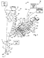
一般に、哺乳動物の体内の消化管を治療するための装置40がここに提示される。装置40は、消化管の壁に材料を導入して壁内に1個以上の移植片を形成するための探針と組み合わせて使用される管被覆部材および/または先端被覆部材を有し得る長手の探針部材41を備えている。図1に示された実施形態では、管被覆組立体42のような管状アセンブリは従来の探針装置44と組み合わせて使用されて、移植片形成用溶液を注射する対象となる消化管の壁の一部に突起形状部を形成する。図1に例示された医学的装置または医学的治療装置40は探針部材または探針44と管被覆組立体42とを有しており、この場合、管被覆組立体42は長手の探針部材41の遠位末端の一部を見なされる。光学視認装置48は探針44に含まれており、針組立体52は長手の探針部材41により滑動自在に保持されているが、この実施形態では探針44により保持されている。治療装置40は、針組立体52の基端部に搭載された供給組立体58を更に備えている。管被覆組立体42は探針44の遠位末端部に着脱自在に搭載されている。別な実施形態では、管被覆組立体の代わりに先端被覆組立体のような短縮された管状アセンブリが探針と組み合わせて使用されて、突起形状部を形成し、溶液を導入する。また別な実施形態では、管被覆部材は先端被覆組立体および探針と組み合わせて使用される。どの実施形態でも、上述の材料から壁内に固形物が形成されて壁を治療する。上述の処置手順で使用するキットがここに提示される。
【0006】
従来型またはその他の好適な胃鏡または内視鏡が探針44について利用され得る。図1から図3に例示されている具他的な探針44は、日本の東京のオリンパス株式会社により製造されているオリンパスCFタイプ40L/I内視鏡である。探針44は、可撓性のある長手の管状部材、すなわち、近位基端54aおよび遠位先端部54bと遠位面56とを有している挿入管54を備えている。ハンドル手段またはハンドル組立体が長手の第1部材すなわち挿入管54の近位基端54aに接続され、従来の探針ハンドル62を備えている。挿入管54は、近位基端54aから遠位先端54bまで軸線方向に延在している複数の穿孔または通路を備えている。中央通路64を含む5つのそのような通路が図2に例示されている。
図1および図2を参照すると、光学視認装置48は探針44と一体形成され、挿入管54の中央通路64により保有された光学素子すなわち対物レンズ66を有している。レンズ66は遠位面56における視野を有し、これは操作者が挿入管の遠位先端54bから前方を視認できるようにする。特に、レンズ66は、第2部材すなわち管被覆部材72の遠位端部72bの内部に形成された圧力チャンバー68の一部と、挿入管の遠位先端部の前方に配置された端部キャップ74の一部との視野を有している。光学視認装置48は探針ハンドル62の近位端部に搭載された接眼レンズ76を更に備えている。第2の照射通路78および第3の照射通路80は、それぞれの光ファイバー組立体すなわち光誘導体82を保有するための中央通路64の周辺で挿入管54の内部に設けられている。接続ケーブル84は、その一部が図1に例示されているが、探針ハンドル62から従来型の光源86まで延びている。第1および第2の光誘導体82は挿入管54およびケーブル84を通って延びて、挿入管54の前方に照明を供与している。
作業通路すなわちチャネル88が挿入管54に更に設けられており、探針ハンドル62に形成されたサイドポート90まで延びている。付加的な通路92は挿入管54を通って延び、吸入作用を供与するための空気入口および/または水入口または管腔として使用され得る。挿入管54は、体内を通して挿入および前進させるのを容易にするように可撓性に富み、所望の方向に遠位面56を選択的に方向付けるための屈曲自在な遠位端部を備えている。複数の指による操作が可能な制御部94が探針ハンドル62に設けられており、とりわけ、挿入管54の屈曲自在な遠位端部を操作し、挿入管54を通して流体を供給および除去することを目的としている。
【0007】
図1および図4を参照すると、針組立体52は、米国メリーランド州ビレリカのシー・アール・バード・インコーポレーティッド(C.R. Bard, Inc.)が製造するバード・フレクシチップ(Bard Flexitip(登録商標))針に類似した改良型の硬化療法用の針のような、どのような従来型のものであってもよい。針組立体52は針部材、すなわち、近位端部96aおよび遠位端部96bを有している針96を備えている。針組立体52は、任意のスリーブ部材、すなわち、近位端部すなわち近位基端98aおよび遠位端部すなわち遠位先端98bを有しているスリーブ98を備えていることもある。スリーブすなわち長手の管状部材98は可撓性プラスチックまたは可撓性金属のような好適な材料から作成されており、針96を受容するように、内部を長軸線方向に貫いて延びる管腔を有している。スリーブ98およびニードル96は互いに相対的に長軸線方向に滑動可能である。この点で、管状針96はスリーブ98内部に滑動自在に配置され、管状針96が遠位端部98bの内部に後退状態にある後退位置から、針96がスリーブ98から遠位方向に突出している伸張位置までの間で移動可能である。ニードル96およびスリーブ98は作業チャネル88とサイドポート90の内部に滑動自在に配置され得るが、各々が或る長さを有しており、遠位端部96bおよび98bが挿入管54の遠位先端54bから先へ延びている場合、または、遠位面56の付近に位置している場合には、近位端部96aおよび98aがサイドポート90に接近できるようにしている。針96には管腔、すなわち、内部を長軸線方向に延在する内部通路100が設けられており、針により液体その他の物質を搬送する。
【0008】
中空針すなわち管状の針96は、内部を長軸線方向に貫いて近位端部96aから遠位端部96bまで延びる内部通路100を有している。改良型の針の遠位端部96bは、ステンレス鋼のような好適な材料から作成され、16ゲージから28ゲージの範囲の寸法を有し、好ましくは、21ゲージから26ゲージの範囲の寸法を有している。図4に最も明瞭に例示されているように、遠位端部96bは内部通路100を形成するための円筒状壁102を有していると同時に、一部がテーパ状端面106によって形成された先鋭な遠位端、すなわち、斜角を設けた遠位端104を有している。少なくとも1個の開口が遠位端部96bに設けられており、テーパ状端部106に設けられた開口108aを含み得る、或いは、該開口を構成の一部とすることがある。開口108aの代用として、或いは、該開口に加えて、少なくとも1個の図示のような複数の開口が円筒状の壁102に設けられていてもよい。たとえば、2つの開口108bおよび2つの追加の開口108cが壁102に設けられる。開口108bは互いに対して正反対位置に配置され、180°離れるように設けられ、開口108cも互いに対して正反対位置に配置され、但し、開口108bから90°オフセットして設けられる。開口108cは開口108bの長軸線方向後部で互いに間隔を設けている。開口108bおよび開口108cはどのような好適な形状または寸法にされてもよく、長円または楕円の形状であるように図示されている。開口108bだけを有している、或いは、開口108cだけを有している針遠位端部96bが設けられても、本発明の範囲に入れられるものと正しく評価するべきである。或る実施形態では(図示せず)、テーパ状端面106は閉鎖されてもよく、また、開口108は円筒状の壁102にしか設けられない。針近位端部96aと針96の中央部はプラスチック、金属、その他の好適な材料から作成され得る。上記以外の針の構成も採用され得る。例えば、針には、概ね円錐形で開口を有していない先鋭な遠位端部すなわち先の尖った遠位端部が設けられていてもよい(図示せず)。また、3個またはそれを越える数の周方向に配置された開口が実質的に等しい分離角で設けられていてもよい。例えば、3個の周方向に互いに間隔を設けた開口の場合は、各々が他の開口から120°の間隔を置いていてもよい(図示せず)。
【0009】
図1に例示するように、流体コネクタ110は針96の近位端部96aに固着または接続され、把持部材すなわちグリップ112はスリーブ98の近位端部98aに固着される。流体コネクタ110は第1のルアー取り付け部分114および第2のルアー取り付け部分116、または、これら以外の好適な取り付け部分を備えており、これらの部分は針96の通路100と連通している。第1のルアー取り付け部分114は図1では被せで覆われている。流体コネクタ110およびグリップ112は互いに相対的に長軸線方向に移動可能であり、針96とスリーブ98の間に相対的な長軸線方向の運動を生じるようにしている。より詳細には、グリップ112は流体コネクタ110に対して針96の近位端部96a上で前後方向に滑動させられる。流体コネクタ110に対してグリップ112を前方に移動させることにより、スリーブ98の遠位端部98bは針96の遠位端部96bを十分に越えて伸張し、針がスリーブ98の内部に十分に後退した状態となる。これとは逆に、流体コネクタ110に対するグリップ112の後方への運動により、スリーブの遠位端部98bは針の遠位端部96bに対して後退させられ、針の遠位端部96bを露出させる。
治療装置40のハンドル手段は挿入管54の近位基端54aに接続された供給組立体58を備えている(図1)。より詳細には、供給組立体58は針組立体52の近位基端に固着されている。供給組立体58は、液体、溶液、または、これら以外の物質を針96の通路100を通して導入し、針の遠位端部96bに設けられた開口108のうちの1個またはそれ以上から排出するための、治療装置40の手段の内部に包含されている。供給組立体58は従来型の注射器または第1の注射器118を備えており、この注射器の貯蔵器またはバレル120にはその前端にルアー取り付け部分122のような好適な取り付け部分が設けられており、また、プランジャー124も設けられており、ルアー取り付け部分122を介してバレル120の内部に液体を放散する。
【0010】
どのような好適な材料であれ、流体が別な流体と別個に、または、互いに関連して体内に導入されると移植片を形成する原料となり得るものが注射器118の中に供給される。水性溶液また非水性溶液が使用され得る流体の一例であるが、不活性の吸収不能な材料が好ましい。このような材料としては、体内に導入されると生体分解性の無い固体を形成する少なくとも1種の溶液が挙げられる。ここで使用されているとおり、固体とは、適度な応力下では認知できる程の流動もしない物質を意味し、それ自体を変形させる傾向にある力(例えば、圧縮力、張力、引張り応力)に抵抗する有限の能力を有しており、常態では有限の寸法と有限の形状とを維持しているが、かかる固体としては、制約なしに、海綿状物質および/または多孔性物質が挙げられる。別な具体例としては、液体として体内に導入することが可能で、かつ、それを元に後で固体が沈殿する非水性溶液が挙げられる。このような非水性溶液の好ましい実施形態は、体内の溶液を視覚化するのを容易にするコントラスト剤を任意で含んでいることがある生体適合性ポリマーおよび生体適合性溶剤から構成される溶液が挙げられる。
特に好ましい移植片形成溶液またはバルキング溶液は、約2.5重量%から約8.0重量%の生体適合性ポリマーと、約52重量%から約87.5重量%の生体適合性溶液と、任意で、約10μm以下の好ましい平均粒子寸法を有している約10重量%から約40重量%の生体適合性コントラスト剤とを含む複合物である。コントラスト剤を含め、ここに述べた百分率はいずれも、コントラスト剤が利用されていない場合には比率調整されることになることを正当に評価するべきである。どのようなコントラスト剤にせよ、水溶性ではない生体適合性のコントラスト剤であるのが好ましい。ポリマー、コントラスト剤、生体適合性溶剤の重量%は完全な複合物の合計重量に基づいている。好ましい実施形態では、水溶性ではない生体適合性のコントラスト剤は、硫酸バリウム、タンタル粉末、酸化タンタルから成るグループから選択される。また別な実施形態では、生体適合性の溶剤はジメチルスルホキシド(DMSO)、エタノール、乳酸エチル、または、アセトンである。
【0011】
「生体適合性ポリマー」という語は、患者体内で使用した場合、使用量単位で、毒性がなく化学的に不活性で実質的に免疫原性であると同時に、生理学的液体中に実質的に不溶性を示すポリマーのことを言う。好適な生体適合性のポリマーとしては、具体的には、酢酸セルロース(二酢酸セルロース)、エチレンビニルアルコール共重合体、ヒドロゲル(例えば、アクリル酸物質)、ポリ(C1−C6)アクリラート、アクリル酸共重合体、アルキル(alkyl)グループとアルク(alk)グループが個別に1個ないし6個の炭素原子を含んでいるポリアルキルアルクアクリラート(polyalkyl alkacrylates)、ポリアクリロニトリル、ポリ酢酸ビニル、酢酸酪酸セルロース、ニトロセルロース、ウレタン/炭酸塩の共重合体、スチレン/マレイン酸の共重合体、これらの混合物が挙げられる。ウレタン/炭酸塩の共重合体の例としては、ジオールで終端しており、その後にメチレンビスフェニルジイソシアナートのようなジイソシアナ−トと反応してウレタン/炭酸塩の共重合体を提供するポリカーボネ−トが挙げられる。同様に、スチレン/マレイン酸の共重合体という語は、スチレン対マレイン酸の比が約7:3から約3:7である共重合体について言及するものである。生体適合性ポリマーはまた、肉体部位でそのまま使用された場合にも非炎症性であるのが好ましい。使用される特定の生体適合性ポリマーは重要ではなく、結果として生じるポリマー溶液の粘性、生体適合性ポリマーの生体適合性溶剤中での溶解度などに関連して選択される。このような要因も本願技術の範囲内に十分に適合している。
【0012】
ポリアクリロニトリル、ポリ酢酸ビニル、ポリ(C1−C6)アクリラート、アクリル酸共重合体、アルキル(alkyl)グループとアルク(alk)グループが個別に1個ないし6個の炭素原子を含んでいるポリアルキルアルクアクリラート、酢酸酪酸セルロース、ニトロセルロース、ウレタン/炭酸塩の共重合体、スチレン/マレイン酸の共重合体、これらの混合物のようなポリマーは、通常は、少なくとも約50,000の分子量を有し、約75,000から約300,000の分子量を有しているのがもっと好ましい。
好ましい生体適合性ポリマーとしては二酢酸セルロースとエチレンビニルアルコール共重合体が挙げられる。一実施形態では、二酢酸セルロースはアセチル基の含有量が約31重量%から約40重量%である。二酢酸セルロース重合体は市場で入手可能なものであるか、或いは、当該技術分野で承認された処置手順で準備されるか、いずれであってもよい。好ましい実施形態では、ゲル透過クロマトグラフィー法により測定されるような、二酢酸セルロース複合物の個数平均分子量は約25,000から約100,000の間であり、約50,000から約75,000の間であるのがもっと好ましく、約58,000から約64,000の間であるのが更にもっと好ましい。二酢酸セルロース複合物のゲル透過クロマトグラフィー法により測定される重量平均分子量は、約50,000から200,000の間であるのが好ましく、約100,000から約180,000の間であるのがもっと好ましい。当業者には明白であるが、他の要因が全て等しい場合には、低い分子量を有する二酢酸セルロース重合体は高い分子量のポリマーと比較して、複合物にもたらす粘性がより低い。従って、複合物の粘性の調整は、ポリマー複合物の分子量を調節するだけで簡単に達成される。
【0013】
エチレンビニルアルコール共重合体はエチレンモノマーとビニルアルコールモノマーの両方の残留物を含む。少量(例えば、5モル%より少量)の別なモノマーをポリマー構成に含有させるか、或いは、そのような別なモノマーが複合物の移植特性を変えない場合には、ポリマー構成上に融合させられる。このような別なモノマーとしては、具体的には、無水マレイン酸、スチレン、プロピレン、アクリル酸、酢酸ビニルなどが挙げられるが、これらに限定されない。
エチレンビニルアルコール共重合体は市場で入手可能であるか、または、当該技術で承認された処置手順によって準備されるか、いずれであってもよい。エチレンビニルアルコール共重合体の複合物は、DMSO中に8重量体積%のエチレンビニルアルコール共重合体を含有する溶液が20℃で60センチポアズに等しいかそれより低い粘性を有しているのが好ましく、20℃で40センチポアズであるのがより好ましい。当業者には明白であるように、他の要因が全て等しい場合には、低い分子量を有しているコポリマーは高い分子量を有しているコポリマーと比較した場合、複合物に与える粘性がより低い。従って、カテーテル搬送に必要となるような複合物の粘性の調節は、コポリマー複合物の分子量を調整するだけで簡単に達成される。
同様に明らかなことであるが、コポリマー中のエチレン対ビニルアルコールの比は複合物の疎水性/親水性全体に影響を及ぼし、次いで、疎水性/親水性が複合物の相対的な水溶性/不可溶性ばかりか、水性溶液中のコポリマーの沈殿率にも影響を及ぼす。特定の好ましい実施形態では、ここで使用されるコポリマーは約25モル%から約60モル%までの間のエチレンと約40モル%から約75モル%までの間のビニルアルコールとを含み、約40モル%から約60モル%までの間のエチレンと約40モル%から約60モル%までの間のビニルアルコールとを含んでいるのが更に好ましい。
【0014】
「コントラスト剤」という語は、哺乳類の被検体に注入する期間中に例えばX線撮影法により監視され得る生体適合性のある(毒性のない)放射線不透過性材料について言及したものである。コントラスト剤は水溶性であるか、または、水に不可溶性であるか、いずれであってもよい。水溶性コントラスト剤の具体例としては、メトリザミド、イオパミドール、ヨータラム酸ナトリウム、ヨーダミドナトリウム、メグラミンが挙げられる。「水に不可溶性のコントラスト剤」という語は、水に溶けない(すなわち、20℃で1ミリリットルあたり0.01ミリグラムよりも低い水溶性を示す)コントラスト剤について言及しており、タンタル、酸化タンタル、硫酸バリウムを具体例に挙げることができるが、これら物質の各々は、生体内使用について適切な形態で、また、好ましくは粒子寸法が10μm以下の状態で市場で入手できる。他の水に不可溶性のコントラスト剤としては金粉末、タングステン粉末、プラチナ粉末が挙げられる。このように水に不可溶性の平均粒子寸法が10μm以下である生体適合性コントラスト剤を以下に説明する。コントラスト剤は水に不可溶である(すなわち、20℃で0.01mg/mlより低い水溶性を示す)のが好ましい。
「生体適合性溶剤」という語は、少なくとも、生体適合性ポリマーが可溶性である哺乳類の体温では有機材料の液体であり、かつ、使用される量の単位内では、実質的に毒性のないものについて言及している。可溶性で生体適合性の溶剤としては、具体的には、ジメチルスルホキシド、ジメチルスルホキシドの類似体/同族体、エタノール、乳酸エチル、アセトンなどが挙げられる。使用される水の量が十分に少なくて、人体への注入時に溶解したポリマーが沈殿する場合には、生体適合性溶剤との水性混合物も使用することができる。生体適合性溶剤は乳酸エチルまたはジメチルスルホキシドであるのが好ましい。
沈殿物内に被包されているコントラスト剤に対して使用されるような「被包」という語は、カプセルが薬剤を封入するのと同程度に、沈殿物内にコントラスト剤を物理的に捕獲することを暗示するような意味合いは無い。むしろ、この語は、コポリマー成分およびコントラスト剤成分などの個々の成分へと分離してゆかない必須の干渉性沈殿物が形成されることを意味するために使用される。
本発明の方法で採用される各種複合物は従来技術の方法で準備されるが、これにより、個々の成分が添加され、その結果生じた複合物を一緒に混合し、最後には、複合物全体が実質的に均質となる。例えば、十分な量の選択されたポリマーを生体適合性溶剤に添加して、完全な複合物を得るのに有効な濃度を達成する。複合物は、その総重量に基づいて約2.5重量%から約8.0重量%のポリマーを含んでいるのが好ましいが、約4重量%から約5.2重量%のポリマーを含んでいるのがより好ましい。必要ならば、ゆっくりと加熱および攪拌する方法を採用して、例えば、50℃で12時間で、生体適合性溶剤にポリマーを溶解させることができる。
【0015】
次いで、十分な量のコントラスト剤を生体適合性溶剤に任意で添加して、完全な複合物を得るのに有効な濃度を達成する。複合物は、約10重量%から約40重量%のコントラスト剤を含んでおり、約20重量%から約40重量%のコントラスト剤を含んでいるのがより好ましく、約30重量%から約35重量%のコントラスト剤を含んでいるのが更にもっと好ましい。コントラスト剤が生体適合性溶剤に溶けない場合は、攪拌を行って、結果として生じる懸濁液の均質化を図る。懸濁液の形成を改善するために、コントラスト剤の粒子寸法は約10μm以下に維持されるのが好ましく、約1μmから約5μm(例えば、平均寸法が約2μm)に維持されるのがより好ましい。或る好ましい実施形態では、コントラスト剤の適切な粒子寸法は、例えば、分別により準備される。このような実施形態では、平均粒子寸法が約20ミクロン以下のタンタルのような水に不可溶性のコントラスト剤が、好ましくは清浄な環境でエタノール(無水)のような有機液に添加される。結果として生じる懸濁液を攪拌したのに続いて、約40秒間、沈静化させることにより、大型の粒子をより速く沈下させることができる。有機液の上澄み部分を除去したのに続いて、液体を粒子から分離させた結果、光学顕微鏡で確認される粒子寸法まで寸法低下させることになる。このプロセスは、所望の平均粒子寸法に達するまで、任意で反復される。
各成分を生体適合性溶剤に添加する特定の順序は重要ではなく、結果として生じた懸濁液の攪拌を必要に応じて遂行し、複合物の均質化を達成する。複合物の混合/攪拌作業は大気圧の無水雰囲気中で遂行される。結果として生じた複合物は加熱殺菌されてから、必要になるまで、密封した褐色瓶または褐色バイアル中に保存しておくのが好ましい。
【0016】
ここに引用された各々のポリマーは市場で入手可能であるが、当該技術で公知の方法によって準備されてもよい。例えば、ポリマーは、重合化触媒または重合化開始剤を必要に応じて採用しながら、ラジカル重合、熱重合、UV重合、ガンマ線照射重合、または、電子ビーム誘導重合のような従来の技術を用いてポリマー複合物を提供することにより、準備されるのが普通である。重合化の特定の態様は重要ではなく、採用される重合化技術はこの発明の一部には含まれ愛。生体適合性溶剤への可溶性を維持するために、ここに記載されたポリマーは橋かけ重合体ではないのが好ましい。
移植片形成溶液または移植片増強液の別な特に好ましい実施形態では、生体適合性ポリマー複合物は生体適合性プレポリマーを含有する生体適合性プレポリマー複合物で代用されてもよい。この実施形態では、複合物は生体適合性プレポリマーと、平均粒子寸法が10μm以下であるのが好ましい、任意の生体適合性の水に不可溶性のコントラスト剤と、任意であるが、生体適合性の溶剤とから構成される。
【0017】
「生体適合性ポリマー」という語は、そのままの位置で重合化してポリマーを形成する材料であって、かつ、患者の体内で使用した場合には、使用された量の単位では毒性がなく化学的に不活性で実質的に免疫原性の材料で、また同時に、生理学的液体中で実質的に不可溶性である材料について言及している。このような複合物は各種反応性化学薬品の混合物として体内に導入された後で、体内で生体適合性ポリマーを形成する。好適な生体適合性ポリマーとしては、具体的には、シアノアクリル酸塩、ヒドロキシエチルメタクリラ−ト、シリコンプレポリマーなどが挙げられる。プレポリマーはモノマーまたは反応性オリゴマーのいずれでもよい。生体適合性プレポリマーは、肉体部位にそのままで使用された場合にも非炎症性であるのが好ましい。
プレポリマー複合物は、完全なポリマー複合物を得るのに有効な濃度を達成するのに十分な量の任意のコントラスト剤を溶液(例えば液体プレポリマー)に添加することにより、準備される。プレポリマーの複合物は約10重量%から約40重量%のコントラスト剤を含んでいるのが好ましく、約20重量%から約40重量%のコントラスト剤を含んでいるのがより好ましく、約30重量%のコントラスト剤を含んでいるのが更にもっと好ましい。コントラスト剤が生体適合性プレポリマー複合物に溶解しない場合は、攪拌を利用して、結果として生じる懸濁液の均質化を図る。懸濁液の形成を改善するために、コントラスト剤の粒子寸法は約10μm以下に維持されるのが好ましく、約1μmから約5μm(例えば、平均寸法が約2μm)に維持されるのがより好ましい。
【0018】
プレポリマーが液体である場合(ポリウレタンの場合など)、生体適合性溶剤の使用は絶対に必要というわけではなく、移植片形成溶液に適切な粘性を提供するのに好ましい場合がある。生体適合性溶剤は、使用されるとすれば、プレポリマー複合物の総重量に基づいて、約10重量%から約50重量%の生体適合性プレポリマー複合物を含んでいるのが好ましい。生体適合性溶剤が使用される場合は、プレポリマー複合物は、通常は、複合物の総重量に基づいて約90重量%から約50重量%のプレポリマーを含んでいる。
特定の好ましい実施形態では、プレポリマーはシアノアクリレートであるが、これは、生体適合性溶剤が無い場合に使用されるのが好ましい。このように使用された時、シアノアクリレート粘着剤は20℃で約5センチポアズから約20センチポアズの間の粘性を有するように選択される。
各種成分を添加する特定の順序は重要ではなく、結果として生じる懸濁液の攪拌を必要に応じて遂行し、複合物の均質化を達成する。複合物の混合/攪拌作業は大気圧下の無水雰囲気中で遂行される。結果として生じる複合物は殺菌処理されてから、必要になるまで、密封した褐色瓶または褐色バイアルに保存されるのが好ましい。
本発明の装置と一緒に使用するのに好適な移植片形成溶液の幾つかの特定の実施形態が、1997年9月16日公布の米国特許第5,667,767号、1996年12月3日公布の第5,580,568号、1997年12月9日公布の第5,695,480号、および、国際公開日が1997年12月4日である国際公開番号WO97/45131号に記載されており、これらの全内容はここに引例として挙げることにより本願明細書中で援用されているものとする。
【0019】
供給組立体58は、第2の注射器126および第3の注射器128の形態で、第2および第3の貯蔵器を更に備えている。第2の注射器126にはジメチルスルホキシド(DMSO)または他の好適な液体が充填されている。第3の注射器128には生理食塩水溶液か、他の好適な水性溶液または生理学的溶液が充填されている。
マニホールドアセンブリすなわち多岐管130が注射器118、126、128を流体コネクタ110に接続するために設けられている。一実施形態では、多岐管130は3個の止水栓132、134、136と少なくとも2個の図示のような4個のポートすなわちルアー取り付け部分とを有している。第1のルアー取り付け部分138は注射器118の前方ルアー取り付け部分122と協働的に組になっている。第3のルアー取り付け部分142および第4のルアー取り付け部分144は付加的に設けられている。第3のルアー取り付け部分142は図1に一部が例示されている管146により第2の注射器126に接続され、第4のルアー取り付け部分108は図1に一部が例示されている管148により第3の注射器128に接続されている。止水栓132、134、136は従来の態様で作動し、ルアー取り付け部分138、140、142、144の間で流体流を方向付ける。本発明のまた別な実施形態(図示せず)では、注射器118は流体コネクタ110または針96の近位端部96aに直接固着される。代替例として、多岐管130にはルアー取り付け部分が何個でも設けられ、或いは、別な構成にして、複数の注射器または他の流体貯蔵器からの流体流を調和させようにしてもよい。
【0020】
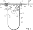
供給組立体58は、複数の別々に予備選択された量のバレル120内の流体を針96に供給するための輸送装置またはガン150を更に備えている(図1および図5を参照のこと)。ガン150はプラスチックまたは他の好適な材料から作成された、注射器バレル120を受容するための円筒状ハウジング152を有している。ハウジング152はベース部154と蝶番158によりベース部154に旋回自在に固着されたカバー部156とから形成されている。ラッチ160はカバー部156に旋回自在に接続されて、ベース部154に係合することによりカバー部156を閉位置にロックする。ハウジング152は注射器118のルアー取り付け部分122を受容するための前方開口162を有している。プラスチックまたは他の好適な材料から作成されたハンドル164はベース部154から懸垂している。ハンドル164は内部空洞166を有している。第1および第2の互いに間隔を設けて離した補強部材168および170は、ハンドル164の前後においてベース部154から下方向に延びている。補強部材168、170は長軸線方向に互いに整列し、各々には中を貫通して長軸線方向に延びて内部空洞166の中へと開放連絡している穿孔172が設けられている。プラスチックまたは他の好適な材料から作成されたロッド174は、穿孔172の内部で滑動自在に配置されている。ロッド174は、自らの後部から上方向にロッドの長軸線に直交して延在してるパドル176を有している。パドル176は注射器プランジャー124の端部に係合するようになっている。人間の手の指を受けるように寸法設定されたリング18がパドル176から後方に延びて、穿孔172の中でロッド174を後方に引く動作を容易にする。
【0021】
ロッド174およびパドル176はガン150の指で操作可能な手段の中に包含されて、注射器118のバレル120とプランジャ124との間の増分的な相対運動を引き起こす。トリガー180は、ハンドル164の前面のロッド174の下で開口182から延びている。トリガーは内部空洞166に設けられた第1および第2の互いに間隔を設けて離したガイド184の間で、ロッド174の長軸線に平行な方向に滑動自在に配置されている。トリガー180は、第1の十分に伸張した位置と第2の十分に後退した位置との間で移動する。レバー186はピン188によりハンドル164に旋回自在に接続されている。レバー186はトリガー180の後方に延在している第1の端部186aと楔型の形状を有しているとともに、ロッド174の底面に形成された複数の長軸線方向に互いに間隔を設けた切欠きのうちの1つに係合する第2の端部186bとを有している。トリガー180が人間の手の指によって後方に引かれると、トリガーはレバーの第1端部186aに係合して、レバー186をピン188を中心として第1のホームポジションから第2の作動位置へと旋回させる。レバーの第2端部186bはこの半ストロークの間に前方に移動して切欠き190のうちの1つと係合し、ロッド174をハウジング152に対して前方に移動させる。パドル176はロッド174に追従し、プランジャー124を増分的にバレル内120に押し入れ、1回ごとのトリガー180の引き動作に備える。
【0022】
固定式止め192がハンドル164に設けられ、トリガー180の後方運動を制限し、従って、トリガー180を1回引くごとに、注射器118から放散されるバレル120内の流体の増分量を決定する。トリガー180の後方移動は、図5に一個が例示されている1個以上の追加ピンまたは追加止め194により選択的に制限され得る。調節可能な制限ピン194はハンドル164の内部に滑動自在に搭載されて、トリガー180の経路からはずれた第1の位置からトリガー180の経路内の第2の位置まで移動し、第2の位置に係合および設置された時には、トリガー180の後方ストロークを選択的に制限する。
コイルスプリングまたは他の好適な変位部材は、一方端がハンドル164の内部に搭載されたピンに接続され、第2端がレバー186の第2端部186bに固着された状態で設けられている。トリガー180に課された指の圧力が解放されると、コイルスプリングはレバー186を後方へと付勢してホームポジションに移動させ、切欠き190との係合から外れる。コイルスプリングはレバーの第1端部196aにトリガー180を開口182からホームポジションへと外方向に押出させる。
【0023】
指で操作可能な調節機構196は針の近位端部96aおよびスリーブの近位端部98aに接続されて、針96とスリーブ98の間の長軸線方向の相対運動を引き起こす。調節機構196は、互いに関連して調節可能である針とスリーブを備えている好適な針組立体と一緒に使用するのに好適なタイプのものであればよい。かかる調節機構196の一実施形態は、ガン150によって保有されている。図1に例示されているように、このような調節機構196は第1の前方ポスト198と第2の後方ポスト200とがカバー部156の頂面から上方向に延在している。長軸線方向に互いに間隔を設けたポスト198とポスト200とはバレル120に直交して延びている。滑動自在な部材すなわちスライドバー202は前方ポスト198に設けられた穿孔(図示せず)に滑動自在に搭載されて、バレル120に平行な方向に前後運動する。拡大ヘッド部204aを有している蝶ねじ204は後方ポスト200に設けられた穿孔(図示せず)に滑動自在に配置される。ねじのヘッド部204aは後方ポスト200に当接し、ねじ204の他方端はスライドバー202の後方端の内部にねじ込み式に受容される。後方ポスト200に対する蝶ねじ204の反時計方向の回転により、スライドバー202は前方ポスト198に向けて後方に移動させられるが、蝶ねじ204の時計方向回転した場合は、スライドバー202はポスト198から離れるように前方へ移動する結果となる。L字型のカプラー206はピン208によりスライドバー202の前方端に旋回自在に接続される。カプラー206は第1および第2の互いに間隔を設けたアーム210が両者の間にスロット212を形成して、グリップ112の中央部を受容する。ねじ214は2つのアーム210の間に延在して、アームをグリップ112にロックし、従って、スリーブ98を針96に対して長軸線方向にロックする。
【0024】
本発明の管被覆組立体42は長手の管状部材または管被覆部材72を有している(図1から図3を参照のこと)。管被覆部材72は剛性材料または可撓性材料のいずれかから形成され得る。例えば、管被覆部材72は剛性のプラスチック管、可撓性のプラスチック管、または、可撓性のシリコン管から形成されていればよく、また、ポリエーテルケトン(PEEK)、ポリプロピレン(PP)、または、フッ化エチレンプロピレン(FEP)のような好適な材料から作成され得る。管被覆部材72は任意で透明であり、かつ、近位部および/または遠位部の端部キャップ74において挿入管54に対して密封摩擦シールを設けるように可撓性を有しているのが好ましい。管被覆部材72は近位端部72aと遠位端部72bを備えている。管被覆組立体42の長さは挿入管54の長さに近似しているのが好ましく、具体的には、100cmないし150cmの範囲の長さを有し、約125cmの長さであるのが好ましく、また、0.5cmないし2.5cmの範囲の直径を有しており、0.75cmないし1.5cmの範囲の直径であるのが好ましい。しかし、管被覆組立体42の長さは、探針44の寸法と、治療を意図した患者と、その他の要因とに依存して変化することがある。
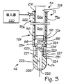
管被覆組立体42は挿入管54の少なくとも一部に回転自在に搭載されている。シール開口218を有しているシール216は管被覆部材72に設けられるが、管被覆部材72の近位端に設けられているように図示されている。挿入管54はシール開口218を通して管被覆組立体42に挿入され、それにより、挿入管54と管被覆組立体42との間に挿入チャンバーまたは圧力チャンバー68を形成することができる。吸入源220は吸入源接続部22を介して管被覆組立体42と接続されて、圧力チャンバー68の内部に負の圧力を生成する。吸入源220は、吸入ポンプまたは従来型の50立方センチメートル容量注射器のような公知の吸入装置を備えていてもよい。
【0025】
管被覆組立体42は、熱シール処理、粘着剤、ねじ、または、プレス嵌めのような好適な手段により管被覆部材72の遠位端部72bに固着された端部キャップ74を有している。端部キャップ74は1cmから10cmの範囲の長さを有しているが、2cmから3cmの範囲の長さであるのが好ましく、好適な材料による射出成形または機械加工により形成することができる。端部キャップ74はポリメチルペンテン(PMP)またはアクリル樹脂のような透明プラスチックから作成されるのが好ましい。端部キャップ74は外表面が外側円筒状表面224の形態であるのが好ましく、外径は管被覆部材72の外径に概ね等しくなる。端部キャプ74は丸み付けされた端部すなわち先端の鈍いノーズ部225を有しており、この部分が消化管への挿入と消化管を通しての前進を容易にし、従って、消化管への損傷を防止し、或いは、損傷を最小限に抑える。端部キャップ74にはチャンバー68と連通している中央通路すなわち穿孔223が設けられており、キャップは先端の鈍いノーズ部225に形成された開口で終端している。好適な材料から作成された光ウインドウ226は開口部でノーズ225に固着され、光視認装置48が端部キャップ74を越えた位置の消化管の視覚的フィードバックを提供できるようにしている。
【0026】
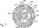
端部キャップ74には外表面224の上まで開いている少なくとも1個の陥凹部または真空空洞227が形成されている。1個、2個、3個、4個、またはそれを越える個数の陥凹部または真空空洞227が管被覆組立体42の遠位先端に設けられることがあるものと正当に評価するべきである。このような真空空洞は図1および図7に例示されているように、端部キャップの付近で周方向に配置可能であって、図1では4この周方向に間隔を設けた空洞227のうちの3つまでが例示されており、図7では4個の周方向に互いに間隔を設けた空洞227が例示されている。端部キャップ74の真空空洞227の各々は細長く、平坦な空洞基底229によって一部が定められる。周璧231は真空空洞227の側壁として機能する。真空空洞の寸法および形状は真空空洞を一緒に利用する医療処置手順によって変わることがあるものと認識するべきである。例えば、真空空洞は半球形状を有することがある。各真空空洞227は少なくとも1つの通路232により圧力チャンバー68に流体接続されるが、この通路は空洞227から中央穿孔223まで延在している。真空開口すなわちアパーチャ228は、図3に例示されているように、各真空空洞227の空洞基底229を形成している端部キャップ74の一部に配置されて、それぞれの内部通路232が真空空洞に入り込む開口部として機能している。各陥凹部壁すなわち基底229には複数のアパーチャ228が設けられており、特に、6個のアパーチャが横2列に配置されると同時に、各列に3個のアパーチャを含んでいる。基底229は平坦であるように図示されているが、基底229は凹状または凸状のような非平坦形状であって、本発明の範囲に入れられるものと認識するべきである。
挿入管54は、遠位先端54bが遠位端部72bに隣接するように、管被覆部材72を通って延在している(図1および図3を参照のこと)。光学視認装置48は、針96が挿入管54の遠位面56から真空空洞227内へと伸張している時には、針の周囲の視覚的フィードバックを提供する。管被覆組立体42は4個の真空空洞227と4個の対応する針ガイド234とを有し得る。スプラインのような識別参照マーク236が、探針44を通して認識可能となる遠位端72bに隣接して管被覆部材72の内部に設けられて、4個の真空空洞227に関して針96の位置を判定するための基準点を基底することができる。管被覆部材72の内側のエッチングとインク添加によるマークのような他の好適な識別参照マーク236が代用として設けられてもよい。識別マーク236の使用は管被覆組立体42の内部の探針44の相対位置、例えば、12時丁度の位置を提供する。
【0027】
逆流性胃食道炎(GERD)の治療のような上位消化管の内部における好適な処置手順について治療装置40を使用することができる。人体238の一部が図6および図7に例示されており、下位食道括約筋242を通って胃244まで延びている食道240の形態を呈する体内窩洞を有している。このような空洞は口(図示せず)の形態を呈する天然肉体開口部により接近可能であり、腔内壁232により形状が定められる。食道240は、口から肛門(図示せず)まで延在している、肉体238の消化管の一部である。食道粘膜246は食道240の腔内壁232の内側層として機能し、胃粘膜248は胃244の壁内壁232の内側層として機能する。食道粘膜と胃粘膜とは扁平円柱上皮接合部250で合流する。壁232は、粘膜層246、248の下方に延在している環状筋252の層と環状筋252の下方の縦走筋254の層とから構成された筋肉層を有している。筋肉層252、254は各々が食道240と胃244の周囲に延在している。壁232は粘膜層と筋肉層の間で延びる粘膜下層すなわち粘膜下組織256を更に有している。粘膜下空間は、潜在的な空間であるが、粘膜層246または粘膜層148と環状筋層252との間で層246または層248を筋肉層252から分離することにより設けることができる。更に、どの筋肉についてであれ、壁232は、単一筋肉の内部または筋肉層と筋肉層の間の筋繊維の拡延と分離により粘膜内に設けられる空間である、粘膜内の潜在的空間を有している。壁232は、少なくとも筋肉層246、248、筋肉層252、254、および、筋肉下組織256から成る深みすなわち厚さを有している。横隔膜−食道の靭帯258と隔膜260とは食道240の周囲で下位食道括約筋242の上方で延在している。
【0028】
本発明の一実施形態では、少なくとも1種の移植片形成溶液が消化管の壁232に導入されて、消化管の壁232に少なくとも1個の移植片264を形成する。操作と使用の1つの好ましい方法では、本発明の装置を利用して、1999年4月15日に出願された米国特許出願連続番号第09/286,245号に開示されたもにに類似している処置手順で、体内に窩洞を形成している壁の一部に移植片形成溶液を注入するが、上述の特許の全内容は引用することで本明細書中に援用されているものとする。特に、管被覆組立体42および治療装置40を本発明に従って利用して、移植片形成溶液を注入する対象となる壁232の一部に突起形状部230を形成する。
或る実施形態では、注射器118には処置手順の準備中に移植片形成溶液が充填される。カバー部156を開いてバレル120をハウジング152の内部に設置できるようにすることにより、注射器118がガン150内部に装填される。リング178を把持してハウジング152に対して後方にロッド174を引くと、パドル176が後退したプランジャー124の背後に配置される。カバー部156は閉じられて、ラッチ160によりベース部154に固着される。その後、医者が必要に応じてトリガー180を引いて、パドル176をプランジャー124の背面に係合させる。
【0029】
針96とスリーブ98が探針44の作業チャネル88に配置された後で、供給組立体58が針組立体52に装着される。代替例として、針組立体を探針44の内部に配置する前に、供給組立体52が針組立体に装着されるようにしてもよい。いずれの場合にも、多岐管130の第1のルアー取り付け部分138を注射器118のルアー取り付け部分122に接続し、また、多岐管の第2のルアー取り付け部分106を流体コネクタ110の第1のルアー取り付け部分156に接続することにより、装着が達成される。カプラー206が下方向に旋回された結果、その第1および第2のアーム176がグリップ172に係合し、ねじ179がきつく締まって2つのアーム176の間のスロット178にグリップ112を固着させる。蝶ねじ204は後方ポスト186に対して反時計方向に回転されて、針96がスリーブ98の内部に十分に後退されるのを確実にする。その後、生理食塩水溶液の注射器128が管148により多岐管130の第3のルアー取り付け部分142に接続され、DMSO注射器126が管146により多岐管の第4のルアー取り付け部分144に接続される。
光ケーブル84を光源86に接続し、かつ、適切な接眼レンズ76を探針ハンドル62に装着することにより、探針44の準備ができる。これに加えて、他の全ての従来型の装着物が探針44に適用される。挿入管54がここでシール216のアパーチャ21を介して管被覆組立体42の内部に挿入される。
【0030】
患者が適切に鎮静剤または麻酔を投与された後で、医者が探針ハンドル62を把持し、管被覆組立体42の遠位端部72bと探針44の遠位先端54bとを患者の口に導入し、挿入管54と一緒に管被覆組立体42を前進させて食道240へと降下させる。光学視認装置48により医者は挿入管54と管被覆組立体42を容易に前進させられる。更に、光学視認装置48は、管被覆組立体42が食道240の内部に適切に配置されるのを医者が確実に行えるようにする。挿入管54と管被覆組立体42は各々が或る長さを有して、遠位先端54bと遠位端部72bが下位食道括約筋242の付近に位置している時には、近位基端54aと近位端部72aとが肉体238の外に来るようにする。端部キャップ74の光学的に透明な材料によって、光ガイド82からの光は食道を照射することが可能となり、従って、ウインドウ226を通しての光学視認装置48による視覚化を向上させることができる。
食道内部に管被覆組立体42を位置決めする上述の方法がここには光学視認装置を利用するように説明されているが、管被覆組立体は光学視認装置の支援が無くても、食道内に導入されるものと認識するべきである。例えば、管被覆組立体42は、所望の治療部位までの所定の距離だけ管被覆組立体の遠位端部を導入するだけで、食道内に位置決め可能となる。管被覆組立体42の挿入距離は、組立体の近位基端を外部から観察することにより、また任意で、かかる近位基端の外表面に設けられた段差(図示せず)により測定することができる。
【0031】
下位食道括約筋242の付近の壁232を治療する処置手順の一部が図6に例示されている。光ウインドウ226を通して挿入管54の遠位面56の前方と管被覆組立体42の前方の視野を得る光学視認装置48の誘導下で、少なくとも1個の真空空洞227が治療を受けるべき壁232の部分に隣接するような位置まで、管被覆組立体42が操作される。次いで、吸入源220が始動されて、管被覆組立体42の圧力チャンバー68から空気を吸入して真空引きをする。従って、負の圧力が圧力チャンバー68と真空空洞227の内部に生じる。この負の圧力は、治療を受けるべき壁232の一部である目標組織を吸引して真空空洞227に投入する吸入効果を生じ、図6に例示されているように、目標組織に突起形状部230を形成する。図6および図7は幾分概略的であり、この点で、食道240の寸法が図6の挿入管54および管被覆部材72の寸法に対して誇張されているものと認識するべきである。挿入管54と管被覆部材72に対する食道240の寸法設定は、図7ではもっと正確である。
針組立体52の遠位端部96b、98bがここで前進させられて、最終的には、針96とスリーブ98のかかる遠位端部が挿入管の遠位先端54bと、管被覆部材の遠位端部72bと、端部キャップ74との付近に位置するまでになる。針96とスリーブ98は各々が、遠位端部96b、98bの各々が挿入管54の内部に後退させられ、従って作業チャネル88の内部に後退させられる第1の位置から、遠位端部96b、98bが挿入管54の端部を越えて遠位方向に伸張した第2の位置まで移動可能となる。針とスリーブは各々が十分な長さを有しており、それは、ガン150を保持している医者が針とスリーブの両方を遠位先端54bから遠位方向に伸ばせる程度である。調節機構196により医者は針96に相対的にスリーブ98を後退させ、針の遠位端部96bがスリーブの遠位端部98bを越えて少なくとも2ミリメートルの選択された量だけ伸びるようにしているが、この量は2ミリメートルから15ミリメートルの間の範囲であるのが好ましい。このような伸張量は、例えば、かかる伸張を蝶ねじ204の回転の関数として相関関係づけてから、この点で後方ポスト200に対する蝶ねじ204の位置を適切に較正することにより、容易に決定することができる。
医者は針96を注射器128からの生理食塩水か他の水性溶液または生理学的溶液の呼び水を注入し、光学視認装置48を用いて生理食塩水溶液が針の絵に端部96bの1個以上の開口108から放散されているのを観察することにより、針の通路100に生理食塩水溶液が充填されることを確実とする。単純化を図るために、適切な流体を針の通路100に向かわせたり、そこから別な方向に向かわせたりするための従来型の止水栓132、134、136の動作をこの処置手順と関連して論じることはしない。
【0032】
医者はスリーブ98および針96を挿入管の遠位先端54bから遠位方向に前進させてそれぞれの針ガイド234に入れ、スリーブ98および針96が突起形状部230の近位に位置するようにする。針96およびスリーブ98をサイドポート90に一層近接させるように移動させることにより、医者はニードルガイド234を通して針96を真空空洞227の中へと伸張させるが、この真空空洞は治療を受けるべき壁232の部分により占有されている。これが針96の先鋭な端部104に壁232の突起形状部230を刺し通させる。光学視認装置48の視野により、医者は針96が針の開口またはガイド234の中に移動するのを観察できるようになり、また、場合によっては、突起形状部230の刺し通しを観察できるようになる。端部キャップ74の光学的に透明な材料により、光ガイド82はかかる視覚化を向上させることができる。針96が真空空洞227内部に伸張する量は、例えば、かかる伸張を蝶ねじ204の回転の関数として相関関係づけてから、上述のように、後方ポート200に関連して蝶ねじ204の位置を適切に較正することにより決定することができる点が着目される。
生理食塩水溶液は壁232に注入されて、このような場合に起こり得ることであるが、食道粘膜246または胃粘膜248を環状筋252から分離させて、生理食塩水溶液が充填された内部空間262を設けている壁232の突起形状部230を更に拡大させる。空間262を設けるのに必要な生理食塩水溶液の量は、0.25立方センチメートルから10立方センチメートルの範疇にあるが、1立方センチメートルから3立方センチメートルの範囲にあるのが好ましいかもしれない。次いで、医者は針96を空間262、駆動227、ガイド234から後退させ、注射器128のプランジャーを引き戻すことにより、或いは、他の好適な方法により、通路100から残留する生理食塩水溶液を引き出す。次に医者は注射器126からのDMSOで針の通路100を洗浄し、生理食塩水溶液が通路100から除去されるのを確実にする。DMSOによる洗浄は、針の遠位端部96bから僅かな量のDMSOが放散されるのを確認することにより判断される。洗浄工程は、生理食塩水の止水栓103の下流側と移植片形成溶液の止水栓101の上流側とでDMSOを導入することにより改善される。ここで、注射器126のプランジャーを引き出すことにより、または、他の好適な手段により、DMSOは通路100から除去される。通路100から生理食塩水溶液を除去し、通路をDMSOで洗浄することにより、移植片形成溶液中のDMSOに起因して移植片形成溶液中に生体適合性ポリマーが注射器118内部で時期尚早に沈殿するのを防止している。次いで、移植片形成溶液が張りの遠位端部96bの開口108で利用できるようになるまで、針の通路100は注射器118により保有されているかかる溶液で呼び水注入される。
【0033】
医者は再度、管被覆組立体42の内部に挿入管遠位先端96bを位置決めし、針96が針ガイド234と整列し、針の遠位端部96bが針ガイド234を通って伸びるようにするとともに、突起形状部230を刺し通して空間262の中へと伸張させる。その後、医者はトリガー180を引いて、所望の予め選択された量の移植片形成溶液を探針44を通って延在している針を通して空間262へと導入する。針の遠位端部96bの開口108は、移植片形成溶液が空間262の中央へとうまく導入されるように位置決めされる。移植片形成溶液中のコントラスト剤が、蛍光透視法による移植片形成溶液の視認を可能にしている。更に、移植片形成溶液を壁232に導入する処理は、超音波により、経腹式または経食道式に監視することができる。移植片形成溶液を空間262に注入する速度は、1分あたり0.1立方センチメートルから1分あたり10立方センチメートルの範囲であってもよい。
移植片形成溶液が壁232に導入されてしまうと、移植片形成溶液の生体適合性ポリマーが沈殿して、1個以上の非連続の堆積物または固体移植片264を形成する(図6を参照のこと)。各移植片ごとに壁232に注入された移植片形成溶液の量またはボーラスは、0.05立方センチメートルから10立方センチメートルの範囲となり得る。空間262内の移植片形成溶液の生理食塩水に対する割合は2:1から1:8の範囲にあるが、移植片形成溶液が約1であるのに対して生理食塩水が2から3の割合の範囲であるのが好ましい。一実施形態では、生理食塩水溶液により設けられた空間262は沈殿物または移植片264の形状を予め限定する。図6から解かるように、そこに図示された分離移植片264は空間262全体よりも小さい空間を占有している。別な実施形態では(図示せず)、生理食塩水よりも大量の移植片形成溶液を壁232に導入して、分離移植片264が生理食塩水によって設けられた空間262を単に充填する以上の効果を生むようにしている。
【0034】
移植片形成溶液の注入前に壁232に生理食塩水溶液のような好適な水性溶液または生理学的溶液を注入することで空間262を設け、この空間が真空空洞227に対して壁232を押圧する。生理食塩水を充填した空間262に移植片形成溶液を注入することで、生体適合性ポリマーの迅速な沈殿とより良好な固化を促進している。このように迅速に固化させることで、移植片264を所望するとおりに成形することが容易となるが、これは、図6に幾分概略的かつ細長い形状で例示されているとともに、真空空洞227の形状に実質的に対応しているように図示されている。生理食塩水溶液が比較的柔軟な海綿状移植片264の生成を促進していることも解かっている。移植片形成溶液の注入と生体適合性ポリマーの固化を完了した後、空間262に残留している溶液は体内に分散され、空間262は移植片264の周囲で収縮する(図7を参照のこと)。
図6および図7では下位食道括約筋242の付近の壁232に1個の移植片264だけが例示されているが、これより多くの移植片が壁232の中に設けられることがある。その準備工程では、針96が突起形状部230、真空空洞227、針ガイドから除去され、プランジャー124を引き戻すことにより、通路100の内部の移植片形成溶液が引き出される。注射器128からのDMSOで針の通路100を充填してから、通路100からDMSOを引き出すことで、針96はDMSOで洗浄される。その後、注射器128からの生理食塩水溶液で針の通路100に呼び水を注入した後で、医者は消化管内部に管被覆組立体42を位置決めし、所望の陥凹部227が壁232の所望の部分に押圧配置されるようにする。次いで、挿入管の遠位先端54bが管被覆組立体42の内部に位置決めされて、かかる空洞227に対応して針96を針ガイド234と整列させ、上述の手順を反復して、1個以上の追加移植片229を設ける。医者は管被覆組立体42に関して挿入管54と一緒に探針44を回転させて、治療を受けるべき壁232の部分に対して真空空洞227’が位置決めされている場合には図6に例示されている第2の針ガイド234’のような所望の針ガイド234と針96を整列させる。
【0035】
壁232に形成された移植片229の数と形状とは変動し得る。移植片形状の特定の具体例は、1999年4月5日に出願された同時係属中の米国特許出願連続番号第09/286,245号に開示されている。例えば、複数の周方向に互いに間隔を設けた移植片(図示せず)は下位食道括約筋242の下方で、かつ、扁平円柱上皮接合部250の下方で壁232の中に設けられる。これら移植片は実質的には、食道240の中心線に沿って胃244の中へと延在している長軸線に直交して延びる平面に配置される。移植片はまた、上述の中心線の周囲で実質的に均等に互いに間隔を設けられており、例えば4個の移植片の場合では、約90°の間隔で設けられる。しかしながら、4個より少数の移植片または4個より多数の移植片を設けることも、それらを周方向に互いに間隔を設けて、中心線の周囲に概ね等しい角間隔で、或いは、非対称的に配置することも可能であることを認識するべきである。移植片の平面は下位食道括約筋242の上方、下方、および/またはそのレベルに配置することができる。
他の実施形態では、一平面には配置されない多数の移植片を形成することができる。更に、移植片の寸法設定、間隔設定、形状によって、食道が拡大状態になるか、部分的癒着状態になるか、或いは、完全に癒着状態になるかが決まる。複数の移植片が、移植片の第1平面から間隔を設けた追加平面に形成されることもある。このような移植片の配列は扁平円柱上皮接合部上で縦走方向に中心を置くことができる。別な実施形態では、1個の移植片を設けて、下位食道括約筋の付近で食道を拡大させ、部分的に癒着させ、または、完全に癒着させることができる。
【0036】
1個以上の移植片を粘膜層以外の壁の各部に形成することができることも、正当に評価するべきである。例えば、1個以上の移植片を筋肉層252と筋肉層254の一方または両方、もしくは、それらの間に形成することが可能である。このような移植片は、下位食道括約筋の付近で食道を拡大させ、部分的または完全に癒着させるように作用することもあれば、筋肉層の伸展性を低下させるように作用することもある。筋肉層252と筋肉層254の内部または両方の間に形成される移植片は多様な形状をに配置されて、その中には、上述の移植片の多様な形状も含まれる。
本発明の装置により設けられた移植片は壁232に容積を加え、胃と食道の間に障壁を形成することができ、かつ/または、壁232の筋肉層252、254の一方または両方に導入された場合は、筋肉層252、254の伸展性を低下させるように作用し、それにより、下位食道括約筋242の付近の壁232の耐性を増大させることができる。移植片は、1999年11月23日に出願された係属中の米国特許出願連続番号第09/447,663号に開示されているようなバルブ状いい高を形成していてもよいが、この出願の全内容はここに引例に挙げることで本明細書中に援用されているものとする。
この発明の方法は、移植片形成溶液を壁232に注入する前に壁232に注入される生理食塩水溶液によって空間262を形成することを含むものと記載されているが、空間262は他の水性溶液または生理学的溶液により、或いは、局部麻酔薬により形成することができるものと認識するべきである。移植片形成溶液の注入前に水性溶液またはその他の溶液を注入することが不可欠であるというわけではないことに留意するべきである。例えば、生理食塩水の注入などにより空間262を事前形成せずに、移植片形成溶液を突起形状部230に直接注入することは本発明の範囲に入る。移植片形成溶液は、本明細書中または他所に記載されている二次的目的で生理食塩水または他の溶液を注入せずに、壁232に直接注入されてもよい。生理食塩水溶液か、他の水性溶液または生理学的溶液は、移植片形成溶液により形成された空間に任意で導入されるが、これは移植片形成溶液を壁232に導入した後のことであり、結果として、移植片形成溶液中に存在するDMSOまたは他の生体適合性溶剤の分散を促進する。こうして、本発明は、治療前、治療中、または、治療後に調節溶液を組織に導入して治療を容易にする点をカバーするのに十分に広いことが解かる。
壁232の内部に複数の移植片を形成する代替の方法では、複数の空間262は注射器128からの生理食塩水溶液によって形成される。その後、注射器118からの移植片形成溶液は、かかる各々の空間に連続的に射出される。
【0037】
本発明の移植片は放射性同位元素、化学療法薬、抗炎症剤、および/または、抗生物質のような他の材料の輸送媒体として使用することができることを認識するべきである。更に、治療装置40は、他の好適な材料から肉体の壁232に移植片を形成するために使用することができる。このような材料は、ウオーカー(Walker)ほか著の「射出可能なポリテトラフルオロエチレン粒子の潜在的代用物としての射出可能なバイオガラス(Injectable Bioglass as a Potential Substitute for Injectable Polytetrafluoroethylene Particles)」泌尿器学ジャーナル148号645頁から647頁(1992年刊)に記載されたタイプの射出可能なバイオガラスのような好適な懸濁剤や、ポリテフ(Polytef(登録商標))のようなグリセリン中のポリテトラフルオロエチレン(PTFE)粒子のような小型粒子種や、バーグ(Berg)に付与された米国特許第5,007,940号、第5,158,573号、第5,116,387号に記載されているような別個のポリマー塊やシリコンラバー塊を含有する生体適合性複合物や、ローイン(Lawin)に付与された米国特許第5,451,406号に開示されているような炭素被膜ビーズを含有する生体適合性複合物が挙げられる。このような、移植片を形成するのに好適な材料としては、ウオレス(Wallace)らに付与された米国特許第4,803,075号に開示されたタイプのコラーゲンその他の生体適合性材料と、これら以外の射出可能な材料が更に挙げられる。
移植片の任意のコントラスト剤は、上述の処置手順の完了後に、移植片を監視することができるようにする。従って、移植片の安定性と形状とは経時的に観察することができる。先に形成した移植片を補足するために、別な処置手順を実施することができる。
【0038】
上述の移植片形成溶液と一緒に使用するための装置は、逆流性胃食道炎の治療以外の目的で他の胃腸処置手順で使用することも可能であり、これは本発明の範囲に入る。例えば、この装置は瘻管の付近の管腔壁を拡大させて、1999年4月5日に出願された係属中の米国特許出願連続番号第09/286,531号に開示されているようなステント設置または他の治療の支援を行うことができるが、上述の特許の全内容は、ここに引用して本明細書に援用するものとする。この装置は、1999年10月4日に出願された係属中の米国特許出願連続番号第09/412,105号に開示されているような静脈および動脈の治療を目的とした応用例も有しているが、上述の特許の全内容はここに引例として挙げることにより本明細書中に援用するものとする。この点で、改良された装置は、食道静脈瘤を治療する目的で下位食道の静脈に溶液を注入するために使用されたり、胃潰瘍などを治療する目的で潰瘍の付近の静脈に溶液を注入するために使用されてきた。更に、同様の装置を使用して、1999年4月5日に出願された係属中の米国特許出願連続番号第09/286,245号に開示されているような肛門括約筋不全症を治療する目的で肛門括約筋の付近の筋肉のような肉体の他の筋肉を膨張させるために使用することができるが、上述の特許の全内容はここに引例として挙げることにより本明細書中に援用されているものとする。同様に、この装置は外側痔静脈の静脈瘤の治療に利用することができる。
【0039】
本発明は、治療を受けるべき肉体の窩洞を形成している壁の一部を成形するための、すなわち、内部の材料を注射するために壁の目標組織を成形するための、観血を最小限に抑えた装置を包含している。真空空洞227により、医者は目標組織を突起形状部230に成形し、一貫した所定の寸法および形状を有している突起形状の移植片264を形成することが有効にできる。一貫した寸法および形状に設定された移植片264を設ける能力は、この処置手順の反復利用性に寄与する。
針96には内部を長軸線方向に貫通して延びる複数の管腔または通路(図示せず)が設けられ、多種の液体を針で別々に搬送することができるようにしていることに留意するべきである。また別な実施形態では、複数の針(図示せず)を探針44のような好適な探針の作業チャネルを通して導入することができる。各々の針は、本発明に従って管被覆組立体と組み合わせて使用することができる。例えば、生理食塩水溶液か、他の生理学的溶液または水性溶液を導入するための針、DMSOまたは他の生体適合性溶剤を導入するための針、更に、消化管の壁232の一部に形成された突起形状部230に移植片形成溶液を導入するための針を別個に提供することができる。また別な代替の実施形態では、1個の針組立体における複数の針を、探針54の1個の作業チャネル(図示せず)を通して導入することができる。移植片形成溶液および生理食塩水溶液は同じ針を通して導入されることがなくなるので、多数の針を備えていることにより、処置手順の複雑さを低減している。従って、例えば、DMSOの呼び水注入工程が削除される。
【0040】
管被覆組立体と探針の構造は、本発明の範囲で変更してもよい。別な実施形態では、複数の針を挿入管および/または管被覆組立体のいずれかに設けてもよい。例えば、図8から図11には、4本の針268、269、270、271を備えている改良型の管被覆組立体266が例示されている。管被覆組立体266は近位基端266aおよび遠位先端266bを有しており、管被覆組立体72に類似しており、同一参照番号を使って管被覆組立体72および管被覆組立体266の同一構成要素を記述している。管被覆組立体266は、実質的に管被覆部材72に類似している管被覆部材276と、管被覆部材276の遠位端部に搭載された端部キャップ280とを有している。端部キャップ280の近位端部には環状の陥凹部282が設けられており、管被覆部材276の遠位端部を受容している(図9を参照のこと)。端部キャップ280は、粘着剤または熱収縮作用のような好適な手段により、または、プレス嵌め、スナップ嵌め、ねじ嵌めにより、管被覆部材276に装着される。端部キャップ74と同様に、端部キャップ280には、基底229および周壁231により定められた少なくとも1個の、また図示したように4個の周方向に互いに間隔を設けた陥凹部227が設けられている。複数のアパーチャ228が基底229に或るパターンで形成され、基底の中を貫通して延びて、通路(図示せず)により管被覆部材276の内部チャンバー68と真空空洞227を連絡している。端部キャップ280は、上述の端部キャップ74と同様に、管被覆部材276と一体形成されてもよく、これは本発明の範囲に入る。
【0041】
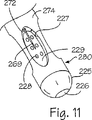
それぞれのスリーブ98(図示せず)の内部に滑動自在に配置されているのが好ましいが、各々の針268、269、270、271は管被覆部材276の側壁274に配置されたそれぞれの通路または管腔272を通って延在している(図10を参照のこと)。針は各々が、図8に例示しているように、管被覆組立体266の近位端部266aに配置された針ポート273を通してそれぞれの管腔272に入る。4個の針ポート273が図7には互いに接近した位置で非対称的に間隔を設けて例示されているが、管被覆組立体266には、非対照的に、または、対照的に互いに間隔を設けた近位端部266aであってもよい可変個数の針ポートが設けられる。側壁の管腔272は管被覆部材276の側壁274を通って延びて、それぞれの真空空洞227で終端している(図11を参照のこと)。4つの管腔272は、それぞれの真空空洞227に対応するように、遠位先端266bで管被覆部材276の長軸線を中心として互いに角間隔を設けている。図8から図11の実施形態では、近位端部266aは、非対称的に間隔を設けたポート273から管被覆部材276の側壁274に設けられた対称的に間隔を設けた管腔272までの間で針268、269、270、271を方向付ける従来型の取り付け部材を備えている。針268、269、270、271は図12に例示されているように多様な長さを有していてもよいが、針には等しい長さが与えられているのが好ましい。図10は管腔272が管被覆部材276の長軸線の周囲で対照的に互いに間隔を設けているのを例示しているが、管腔272は長軸線を中心として非対称に互いに間隔を設けていてもよい。
【0042】
図12に概略的に例示されているような、異なる長さの針268、269、270、271を設けて、体内の個々の針を手術中の医者が識別するのを支援することができる。例えば、長い針は相対的な12時丁度の位置に置かれ、短い針は相対的な10時丁度の位置に置かれるが、このような位置は、各針が装置40に等しく挿入されていれば、医者に容易に認識される。代替例として、針は互いに異なる色づけをされたり、異なる証印が付されて、それぞれの識別を助けることもできる。多様な長さの針は識別マークと組み合わせて使用して、体内の針を識別する支援を行ったり、管被覆部材に関するそれぞれの相対的な位置を判定することができる。図3に例示されているような識別マーク236は管被覆組立体42の内部の位置を提示し、このマークから針の位置を確認できる。例えば、図10については、針270は図10には例示されていない識別マークに隣接した12時丁度の位置に位置決め可能であり、従って、針271は3時丁度の位置に設置されることになり、針268は6時丁度の位置に、針269は9時丁度の位置に設置されることになる。管被覆部材276の遠位端部276bに配向されている時の針の伸張の長さは、管被覆組立体266の内部に配置された識別マークを参照しながら視認すれば、それぞれの空間的位置を明確にする。多様な長さおよび/または多様な色を備えた管被覆組立体は識別マークを付けずに設けられることを認識するべきである。
図8から図12の実施形態の用途と動作とは上述の第1の実施形態のものに類似している。例えば、管被覆組立体266は或る長さを有しており、その長さは、遠位端部266bが下位食道括約筋の付近にある時には、近位端部266aが体外にあって、医者が針268、269、270、271を操ることができるようにする程度である。複数の針を設けることは、別個の針は各真空空洞227の方を向けられて、複数の真空空洞の対応する針ガイドと探針の針をうまく整列させる必要を除去しているという点で有利である。
【0043】
図13および図14に例示された別な実施形態では、管被覆部材274は、それぞれの真空空洞227において一緒に終端している複数対の互いに平行な管腔を備えている。より詳細には、空洞内の管被覆部材276は複数対の管腔272、272’を有しており、これらは側壁274を通って互いに平行に延びて、1個の真空空洞227の内部で終端している。1対の針278、278’は対応する1対の管腔272、272’を通って延びており、図14に例示されているように、対応する真空空洞227に挿入可能である。この実施形態の利点は、各針が1種の溶液の専用とされており、従って、針に呼び水を再度注入する必要を排除している。例えば、針278は注射器128の生理食塩水溶液の専用とされてもよく、針278’は注射器126のDMSOの専用とされてもよい。
【0044】
別な実施形態では、1個の真空空洞284を有している管被覆組立体283が設けられる。図15に例示されている管被覆組立体283は実質的に管被覆組立体266に類似しており、同一参照番号を使用して管被覆組立体266および管被覆組立体283の同一構成要素を記述している。管被覆部材276と類似している管被覆部材285と端部キャップ286とが組立体283に包含されている。端部キャップ286は射出成形のような好適な手段により形成されるが、光学的に透明な材料から作成されるのが好ましい。端部キャップ286は1cmから10cmの範囲の長さを有し、1cmから3cmの範囲の長さが好ましいが、更に、粘着剤(図示せず)のような好適な手段により管被覆部材285に固着されている。端部キャップは外側円筒状壁を有しており、ここには1個の窪み部分すなわち陥凹部284が形成されているとともに、管被覆部材285の側壁管腔272と連絡している長軸線方向に延びた管腔287が設けられている。管腔287は真空空洞284で終端しており、真空空洞は基底288と周壁289により定められている。複数の通路またはアパーチャ290は基底288を通って延び、管被覆組立体283の内部チャンバー68と連絡している。アパーチャ290は縦走方向に延びた4列の各列ごとに2個のアパーチャが在るパターンで配置されている。保護スリーブ98を備えた針96は管腔272および管腔287を通って延び、管被覆組立体の近位基端に接近できるようにして、真空空洞284の内外へ移動できるようにしている。端部キャップ286は先端が鈍く丸み付けされた閉じたノーズ部291が形成されている。
端部キャップ74に関して先に言及されているように、光ガイド82で食道を照射できるようにすることによって、端部キャプ286の光学的に透明な材料は視覚化を向上させている。比較的短い端部キャップ286と、挿入管54より遠位に位置する比較的大きい径の圧力チャンバー68により、光学視認装置48は端部キャップ286から遠位方向を見た比較的大きい視野を有することができる。端部キャップのノーズ部の形状は視認装置48が得ることのできる画像のタイプに寄与している。図15の実施形態では、丸み付けされた凸状のノーズ部291は光学装置48により視認された画像を拡大する。
【0045】
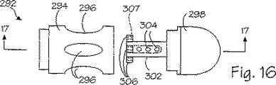
本発明の端部キャップは多数の構成要素から形成される。ズ16に例示された実施形態では、上述の管被覆部材に類似した管被覆部材に端部キャップ280に関して先に論じた態様で搭載可能である、端部キャップ292が設けられる。代替例として、端部キャップ280は以下に論じる端部キャップ332のように分離したピースであってもよく、端部キャップ332に関して以下に論じるような好適な手段により挿入管54に着脱自在に搭載されている。各キャップ292は円筒状のスリーブ部材294を有しており、この部材には、少なくとも1個か、図示したように複数個の開口297が形成されて、開口と等数の真空陥凹部297を端部キャップに設けている。スリーブ部材294は終片298の内側円筒状部分302を受容する。円筒状部分302は端部キャップ292の真空陥凹部または空洞297のベースとして機能する。真空アパーチャ304は円筒状部分302の内部に形成され、該円筒状部分の中を貫いて延び、真空空洞297に吸引力を与えている。針ガイド306は各々の真空空洞ごとに、内側円筒状部分302から半径方向外向きに延在しており、中を貫通して延びる開口307が形成されて、挿入管54の内部に保有されているそれぞれの針96とスリーブ98を真空陥凹部206に向けてガイドする。
図17に例示された端部キャップ292の動作については、突起形状部230が上述の態様で真空空洞297に形成される。次いで、手術中の医者は針96を突起形状部の中に伸ばして、移植片264を形成し、従って、壁232を治療する。突起形状部230は針注入期間中は光学視認装置48を用いて視覚化される。
【0046】
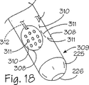
ここに記載される真空空洞は、多様な所望の形状または幾何学的形状の突起形状部を形成するために、互いに異なる形状または幾何学的形状の態様を採ることがある。例えば、上述の端部キャップ74、280、286のいずれにも実質的に類似している端部キャップ309には、実質的に形状が半球状である1個以上の陥凹または真空空洞308が設けられる(図18を参照のこと)。同一参照番号を用いて端部キャップ74、280、286、309の同一構成要素を記述している。開口または陥凹部308の各々は断面が実質的に円形であり、断面が実質的に円形である壁310により定められる。開口311の配列は各々の陥凹部または真空空洞308の壁310に設けられている。開口311は、端部キャップ309に設けられた通路または管腔(図示せず)により真空源(図示せず)と連絡している。例えば、上述の針96に類似している針(図示せず)は、通路または針ガイド312により真空空洞308の各々に挿入可能である。
また別な実施形態では、細長い、または、楕円形の少なくとも1個の陥凹部または真空空洞314を有している端部キャップ313が設けられる(図19を参照のこと)。端部キャップ313は端部キャップ309に実質的に類似しており、同一参照番号を使用して端部キャップ309および313の同一構成要素を記述している。図示のように、複数の真空空洞314が端部キャップ313に設けられている。各々の楕円形状の真空空洞は、実質的に平坦な基底315と実質的に形状が楕円である周囲側壁316とにより定められる。
【0047】
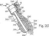
管被覆組立体42に実質的に類似している管被覆組立体317が図20に例示されており、同図では、同一参照番号を用いて管被覆組立体42および317の同一構成要素を記述している。管被覆組立体は端部キャップ318が管被覆部材72の遠位端部に固着され、この端部キャップ318は管被覆部材72と一体形成されているように特に図示されている。少なくとも1個か、図示のように複数個の陥凹部または真空空洞319は端部キャップ318の外側円筒状壁に形成されている。より詳細には、管被覆組立体317は4個の真空空洞319が管被覆組立体317の長軸線を中心として90°の等しい分離角度で周方向に互いに間隔を設けて配置されている。各々の真空空洞は、真空空洞の実質的に全長をゆるやかに湾曲させて、涙粒の半分体に似た形状を有するように、弧状で凹状の壁320により定められる。
管被覆組立体317の動作と用途は管被覆組立体42に関して先に論じた処置手順に類似している。真空空洞319のちの1個が目標組織に隣接して配置された状態で、管被覆組立体317と探針54とが消化管の内部に適切に位置決めされた後、手術中の医者により吸入源220を始動させて、チャンバー68と各々の真空陥凹部318に負の圧力を設け、従って、壁232の一部を所望の真空空洞319へと真空引きする。これにより、突起形状部230は実質的には真空空洞の形状を有している上述のような真空空洞へと形成される(図20を参照のこと)。針96はそれぞれの針ガイド234を通して真空空洞へと挿入され、突起形状部230を刺し通し、突起形状部の内部に移植片を形成する。移植片形成溶液を突起形状部に注入する前に、針96が図20の環状筋層252を刺し通しているのが例示されている。陥凹部壁320の弧状の形状は壁232に形成された移植片の断面形状に影響を与える。
【0048】
図から明らかなように、互いに異なる形状の真空空洞または陥凹部を利用して多様な形状の突起形状部230を形成することができる。例えば、図18に例示された空洞陥凹部308を利用して、実質的に半球形状の突起形状部と、従って、これと同じ形状の移植片とを形成することができる。前述のことから、多数の別な空洞形状および空洞プロファイルとが本発明に従って利用することができる。例えば、他の端部キャップに、四角形または矩形の形状を有している1個以上の真空陥凹部を設けることができる。
本発明の装置には、装置の遠位部分を中心として周方向に延在する多数の真空空洞を設けることもできる。管被覆組立体42に実質的に類似した管被覆組立体321の遠位部が図21と図22に例示されている。同一参照番号を図21と図22に用いて、管被覆組立体42と管被覆組立体321の同一参照番号を記述している。管被覆組立体321は、好適な手段により管被覆部材72の遠位端部に端部キャップ322が固着されている。少なくとも1個か、図示のように1個の陥凹部または真空空洞323が端部キャップ322の外側円筒状壁に形成されている。陥凹部または真空空洞323は、図21に例示されているように、管被覆組立体321の長軸線を中心として360°の角度で周方向に延在しており、半球状の壁324により定められる。複数の周方向に配置された真空アパーチャ326は壁または陥凹基底324を貫いて延びている。真空アパーチャ326は、半径方向に延び、かつ、管被覆組立体324の長軸線を中心として周方向に互いに間隔を設けて、中央穿孔223により周方向陥凹部323を圧力チャンバー68と流体接続し、陥凹部323に吸引力を与えている。針96は、陥凹部壁324の近位部を通って内部チャンバーの遠位端部から延在している複数の周方向に互いに間隔を設けた穿孔または針ガイド330により、真空空洞323の選択された部分に挿入可能である。
管被覆組立体321の動作については、吸入源220が始動されると、治療を受けるべき壁232の一部が周方向真空陥凹部323へと引き込まれる。壁232のかかる部分は周方向真空陥凹部323の形状を実質的に呈しており、1999年11月23日に出願された米国特許出願連続番号第09/447,663号に開示されているタイプの弧状の突起形状部のような少なくとも一部が弧状の突起形状部または周方向の突起形状部を形成することができる。針ガイド330は周方向真空陥凹323に針96を案内する支援をするのと同時に、そこに形成された突起形状部にも針を案内する。1本の針96で1回の注入を行う方法を利用して、真空空洞323に引き入れられる壁232の該当部に移植片を形成することができるが、代替の処置手順では、1本以上の針96により多数回の注入が行える。
【0049】
他の周方向陥凹部の幾何学的形状を利用して、多様な突起形状部と移植片の形状とを設けることができる。例えば、多様な所望形状の周方向突起を形成するために、図18から図20に例示されたプロファイルまたは断面のような好適なプロファイルが、真空空洞323に類似した周方向真空陥凹部に設けられる。管被覆組立体の全周よりも短い管被覆組立体の長軸線を中心として角度を設けて延在している弧状の真空陥凹部が設けられる。例えば、管被覆組立体の周囲で約90°または180°で延在している真空空洞が設けられ、これは本発明の範囲に入る。
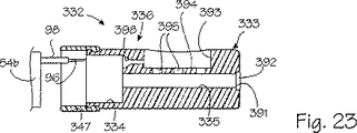
図23に例示したような、本発明の別な実施形態では、短い管状アセンブリすなわち先端被覆組立体332が挿入管54のような従来型の探針と組み合わせて使用されている。より詳細には、第2部材すなわち先端被覆組立体332は挿入管54の遠位端部54bに取外し自在に装着または搭載される。このように、先端被覆組立体332は挿入管54の長さに沿って延在している訳ではなく、挿入管と一緒に使用した場合は、肉体238外部に接近可能な近位部分を有してはいない。この点で、先端被覆組立体332は1cmから10cmの範囲の長さを有しており、2cmから3cmの範囲の長さであるのが好ましい。先端被覆組立体はプラスチックまたは他の好適な材料から作成された円筒状本体または端部キャップ333を備えている。端部キャップ333は0.5cmから2.5cmの範囲の直径を有しており、直径は0.75cmから1.5cmの範囲であるのが好ましい。長軸線方向に延在している内部チャンバー334は端部キャップ333の近位基端に設けられており、中央穿孔335はチャンバー334から遠位端部または端部キャップ333の開口391まで遠位方向に延びている。少なくとも1個か、図示のように1個の真空陥凹部または空洞393が端部キャップ333の外側円筒状表面に設けられている。平坦な壁または基底394により陥凹部または真空空洞393は部分的に定められ、空洞は、上述の形状を含む好適な寸法および形状を有していればよい。複数の穿孔またはアパーチャ395は基底394を貫いて延び、真空空洞392を中央穿孔335と流体接続する。
【0050】
可撓性のある管状部材すなわちスリーブ397を含む手段が先端被覆組立体332に包含されて、挿入管または探針54の遠位端部54bに着脱自在に端部キャップ333を搭載する。スリーブ397はシリコーンのような好適な材料から作成され、対立的に寸法設定にされ、遠位端部54の一部を覆って延在してそこに摩擦嵌めで固着されるのに十分な弾性を有している。端部キャップ333の近位端部は、先端被覆組立体32が挿入管54に固着された時には、概ね遠位端部54bに当接する。スリーブ397はシールとして更に機能し、従って、挿入管54と端部キャップ33の間の流体密封接続部を設けるように機能する。少なくとも1個の長軸線方向に延在する穿孔またはガイド398は内部チャンバー334の遠位端部から真空空洞393の近位端部まで延びて、挿入管54により保有されている針96を真空空洞393に着脱自在に挿入できるようにする。
動作中および使用中は、先端被覆組立体332は、管54を肉体238に挿入する前に、挿入管54の遠位端部54bに搭載される。挿入管が壁232の一部を空洞393に引き込むのが望ましい時には、挿入管によって「内部チャンバー334に、従って、真空空洞393に吸引力が与えられる。挿入管54によって滑動自在に保有され、肉体238の外部から操作可能である針96は、空洞393に形成された突起形状部230に挿入されて、移植片形成溶液を突起形状部230に注入し、従って壁232にも上述の態様で注入する。
【0051】
哺乳動物の体内の窩洞の壁に移植片を形成する装置の別な実施形態が図24に例示されている。該図の装置337は挿入管54と、上述の先端被覆組立体332に実質的に類似する先端被覆組立体338とを備えている。同一参照番号を図24で使用して、先端被覆組立体332および先端被覆組立体338の同一構成要素を同定している。端部キャップ333に実質的に類似している端部キャップ339と、可撓性のある取付けスリーブ334とが先端被覆組立体338に包含されている。端部キャップ339は長軸線方向に中を貫いて延在している中央通路または穿孔340を備えており、光学視認装置43を用いると先端被覆組立体338から前方が見られるようにしている。比較的に短い先端被覆組立体332は光学視認装置48により前方を見るのが容易になる。このような前方視認は、比較的大きい径を有する中央穿孔340を形成することにより更に向上させられる。先端被覆組立体338は中央穿孔340の遠位端部に光ウインドウ392のような光ウインドウを備えてはいない。その結果、穿孔340はアパーチャ395と端部キャップ339の真空空洞393とに負の圧力すなわち吸引力を与えることはできない。
真空空洞393に吸引力を与えるための外部手段が装置337に設けられ、外部手段は、挿入管54に沿って外部へと延びる外部吸入管342を備えている。吸引管342は近位端部342aが従来の止水栓および流体取付け組立体343に接続されて、管342が流体密封の態様で上述の吸入源220のような好適な吸入源に接続されるようにしている。吸入管は、端部キャップ339の内部へと延びて、流体密封の態様でアパーチャ395に接続されている遠位端部342bを備えている。外部吸入管342は、吸入管54の周囲に同心配置されて、吸引管342をその外周部に押圧保持するようにした小型のラバースリーブ344のような好適な手段により、挿入管54に沿って固着され得る。
【0052】
装置337は、先端被覆組立体338と挿入管54の上を滑動自在に伸張してそれらと一緒に回転運動する、多数ウインドウの管被覆部材346を備えている。管被覆部材346はプラスチックのような好適な材料から作成され、先端被覆組立体と挿入管を滑動自在かつ回動自在に受容するように、中央通路347が設けられている。管被覆部材346は近位基端346aおよび遠位先端346bを有しており、また、遠位先端346bが上位消化管のような肉体の所望の空洞の内側で目標組織に隣接した位置にある場合には、近位基端346aが体外に位置するような程度の長さを有している。複数個の、図示したように4個の周方向に互いに間隔を設けた側部開口348が遠位先端346bに形成される。遠位開口すなわち端部開口349が管被覆部材346に更に設けられている。各々の側部開口348は、真空空洞393の開口の寸法および形状に近似している寸法および形状を有しており、管被覆部材346に長軸線方向に位置決めされて、先端被覆組立体338が管被覆部材346の端部に当接した時には、開口348のうちの1個を真空空洞393と選択的に整合させることができる。端部開口349は先端被覆組立体339の中央穿孔340の寸法に近似する寸法および形状を有して、管被覆部材346を通して前方を視認できるようにするのが好ましい。フランジ部材またはハンドル350が管被覆部材346の近位基端346に形成されて、挿入管54と先端被覆組立体338の周囲で管被覆部材が回転するのを容易にしている。
【0053】
動作中と使用中は、管被覆部材346は肉体窩洞の内部で先端被覆組立体338と挿入管54が回転するのを容易にするよう機能するが、特にこの場合は、管被覆部材はかかる肉体窩洞の内部で包囲するように配置される。例えば、探針が肉体窩洞で包囲するように配置されている場合は、軟組織を探針と並置することが起こり、従って、窩洞の内部で探針が回転するのを防止することができる。この結果、窩洞の内部で望ましい位置に探針を術中の医師が設置する能力に制約が加わることがある。管被覆部材346は、多数側部開口またはウインドウ348を有しているが、食道240または他の肉体通路の内部で管被覆部材を一度だけ回転させることにより、管被覆部材346の位置を術中の医師が調節できるようにし、それから、管被覆部材の側部ウインドウ348と先端被覆組立体の真空空洞393が整合している複数の位置のうちの1つ以上の場所まで、管被覆部材の内部で挿入部材54と先端被覆組立体338とを回転させることにより、食道または他の肉体通路の複数の領域を医師が治療できるようにすることによって、この欠点は克服される。管被覆部材346が食道内部で反復して回転させられることがないので、軟組織を装置337と並置する危険は低減され、かつ/または、除去される。
先端被覆組立体338には、たった1個の真空空洞393が設けられている。これは、多数の真空空洞のうちのわずか1つが壁232に係合し、残りの真空空洞が消化管の内部で開くことにより、選択された真空空洞に共通の吸入源を供給する能力のある真空力を低減させてしまう管被覆組立体または先端被覆組立体と比べて、真空空洞393に形成された突起形状部に及ぼされる吸入力を有利に増大させている。外部吸入管342により、専用の真空供給が1個の空洞393に設けられる。上述のように、真空空洞393は術中は管被覆部材346の所望の側部開口348と整合可能である。
前方の視覚化は、短縮された先端被覆組立体338と、先端被覆組立体における大きい径に設定された中央穿孔340と、先端被覆組立体338および管被覆組立体346の遠位端部の塞栓されていない開口とにより、最適化される。
【0054】
別な実施形態では、目標の壁部分に真空陥凹部を押圧付勢して、壁の中の移植片形成を向上させる手段を備えている装置が提供される。例えば、図25に例示された装置351はバルーンの形態の付勢手段を有している。装置351は先端被覆組立体332に実質的に類似する先端被覆組立体352を有している。同一参照番号を図25で使用して、先端被覆組立体352および先端被覆組立体332の同一構成要素を同定している。先端被覆組立体352は、可撓性スリーブ397のような好適な手段により挿入管54の遠位端部54bに搭載される。
膨張可能なバルーン353は、真空空洞393の概ね反対側で端部キャップ339に設けられた陥凹部354の内部に保有されている。外部搭載型の空気給送管または空気供給管355が膨張可能バルーン353に設けられている。供給管355は従来型の止水栓および流体取付け組立体399に接続された近位端部355aを有しており、管355を好適な流体膨張供給部(図示せず)に流体密封の態様で接続できるようにしている。供給管は、端部キャップ339内へと延びて流体密封の態様でバルーン353に接続する遠位端部355を有している。空気供給管355は、ラバースリーブ344などにより、上述の吸入管342と同じ態様で挿入管54の外部に搭載される。代替例として、挿入管54の内部の空気管または膨張流体管はバルーン353を膨張させるために設けられる。
【0055】
動作中と使用中は、バルーン353は挿入管54および先端被覆組立体338を付勢して、空洞393内部に捕獲されて移植されるべき壁232の部分を押圧するために使用される。移植の最中である食道または他の肉体通路の壁の反対部分に端部キャップ339を押し付けることにより、バルーン353は壁232に真空空洞393を押圧設置し、かつ、真空空洞の内部に吸引力を生じるのを容易にする。バルーン353は吸入源220とは無関係に使用されるか、或いは、吸入源220と関連して使用されて、食道または他の肉体通路の壁の目標部分を移植空洞393の中へと付勢し、針96による注入を行うことができる。バルーン353のようなバルーンが上述の発明の実施形態のいずれかに設けられることも認識されるべきである。
バルーン352が吸入源220と関連して使用されると、外部搭載型の吸入管342と空気吸入管355とが設けられる。一実施形態では、外部搭載型の2元式管腔の管が設けられるが、ここでは、管の一方の管腔は真空空洞393と流体接続されてそこに吸引力を与え、管の他方管腔はバルーン355に流体接続されて、そこに空気を供給する。
【0056】
本発明の方法に従って、壁に突起形状部を形成し、人体の消化管の上位部を定める壁を治療する際に使用するためのキット356が図26に概略的に例示されている。キット356は、ダンボールまたはプラスチックのような好適な材料から作成されて、その内容物を搬送するようにしたパッケージ358から成る。図26に例示された具体的なパッケージ358は、底面壁360と四側面壁362と頂面壁364から形成された箱である。頂面壁364の一部が図26では切り取られており、壁360、壁362、壁364によって定められる内部空間366を顕わにしている。受容体すなわちパッケージ358の内容物は内部空間366に配置されている。
針組立体52はパッケージ358により内部空間366の中に保有されている。上述のように、針組立体52はスリーブ98および流体コネクタ110の内部に針96を有している。キャップ368はスリーブ98の遠位端部98bに取外し自在に装着されて、貯蔵および組立ての最中に、針の遠位端部96bにより使用者が我知らず穴を開けてしまうのを防止している。流体コネクタ110のルアー取付け部分114、116は図26にキャップを被った状態で例示されている。キット356は、貯蔵器または注射器118と、好適な移植片形成溶液の容器またはバイアル370とを更に備えている。1つの好ましい実施形態では、移植片形成材料は上述の非水性移植形成溶液である。バイアル370は針を刺し通し可能なキャップを有しており、注射器118のルアー取付け部分122は、任意でキット356に含まれる標準の皮下注射針373に装着されるが、この針はキャップ372を刺し通すことによりキャップ372に着脱自在に接続されて、注射器118を装填する。上述のように、注射器118のルアー取付け部分122も針組立体52の流体コネクタ110に着脱自在に接続される。
【0057】
先端被覆組立体332のような管状組立体はキット356に含まれて、上述のような胃腸壁に突起形状部を形成する。先端被覆組立体332が図26に例示されているが、キット356は、先端被覆組立体332の代わりに、または、該組立体に加えて、図1から図3に例示された管被覆組立体42のような長い管被覆組立体を含むこともある。キット356はまた、任意で、注射器であるとして図26に例示されている好適な吸入源220も含み、端部キャップ333の圧力チャンバーおよび真空陥凹部393の内部に負の圧力を生成する。
注射器118から複数回分の非連続の所定量の非水性溶液を供給するための、ガン150のような搬送機構がキット356に任意で含まれる。注射器118はガン150の内部に搭載されているとして図26には例示されている。キット356の付加的な任意の構成要素としては、注射器126のような第2の貯蔵器と、バイアル374の形態の、DMSOのような生体適合性溶剤の容器とが挙げられる。バイアル374は針を刺し通すことができるキャップ376を備えており、注射器126は、任意でキット356に含まれる標準的な皮下注射針377に装着されるルアー取付け部分378を有しており、この針はバイアル374のキャップ376に着脱自在に接続されている。キット356は止水栓132、134、136のような図26に例示していない複数の止水栓を更に任意で備え、上述の態様で針組立体52を通る液体の流れを選択的に方向付けることができる。生理食塩水溶液(図示せず)のような水性溶液の第3の貯蔵器または注射器、および/または、バイアルも任意でキット356に含まれてもよい。
【0058】
キット356は上述の処置手順で、または、他の処置手順で使用されて、上位消化管の壁232を治療することができる。キット356の針組立体52は、図1から図3、図6および図7を参照しながら上述の探針44のような探針装置と一緒に使用されるのが好ましい。この点で、針組立体52は探針44を通して、もっと特定すると、探針の挿入管54の作業チャネル88を通して消化管に導入するように対立的に寸法設定される。注射器118には、注射器118のルアー取付け部分122を皮下注射針373に接続して、バイアル330のキャップ332を刺し通すような好適な手段により、バイアル331から非水性溶液が装填される。充満すると、注射器118は上述の態様で流体コネクタ110に装着される。探針44は、挿入管54の遠位先端54bが治療領域の付近に位置するようになるまで、食道240に導入される。その後、針組立体22の遠位端部96b、98bは挿入管遠位先端54bの付近に位置する。
ガン150がこのように使用される場合は、注射器は118は上述の態様でガンの内部に搭載される。更に、任意の注射器126を使用して、処置手順期間中は、針組立体52を通してDMSOのような好適な生体適合性溶剤を供給することができる。注射器126はそのルアー取付け部分378を皮下注射針377に着脱自在に接続してバイアル374のキャップ376を刺し通すことにより充満される。その後、注射器126は上述の態様で流体コネクタ110に接続される。更に、任意の生理食塩水溶液の注射器128は、処置手順期間中は、上述の太陽で流体コネクタ110に接続されて使用に付される。
【0059】
先端被覆組立体332は挿入管54の遠位端部54bに搭載されて、肉体238の目標壁に移植片を形成するのを容易にすることができる。
キット356は気管−食道の瘻管、静脈、動脈、胃潰瘍を上述の態様で治療するために使用することができる。キット356はまた、消化管または窩洞の壁に移植片を形成するのが望ましい場合には、体内の上位消化管または他の好適な窩洞の内部で、上記以外の処置手順でも使用することができる。
【0060】
本発明の治療装置の別な実施形態が図27から図29に例示されている。各図に例示された治療装置の一部として、挿入管54と一緒に使用するための追加部材すなわち短い先端被覆組立体411が挙げられる。先端被覆組立体411は上述の先端被覆組立体332に類似しており、PMPまたはアクリル樹脂のような好適な硬質プラスチックから作成される終片または端部キャップ412を備えている。終片412は光学的に透明であるのが好ましい。終片412は近位基端412aと遠位先端412bが長軸線上に中心を置かれており、1cmから10cmの範囲の長さを有し、1cmから3cmの範囲の長さであるのが好ましい。
終片の遠位先端412bは外側円筒状壁416から形成される。少なくとも1個の窪み部分または陥凹部417が先端被覆組立体411に設けられており、図27から図29に例示されているように、1個の陥凹部417が遠位先端412bの外側円筒状壁416に形成される。陥凹部417はカップ型の形状にされ、基底壁または基底418、周壁または縁419から定められる。終片412は周壁419の遠位端部により定められた先端の鈍いノーズ部422を有している。光ウインドウ423の形態の平坦な壁は、先端の鈍いノーズ部422から、終片の長軸線に対して斜角を設けて延在している。ウインドウ423は実質的に陥凹部417の反対側に配置され、陥凹部417の下方で延びている。
先端被覆組立体411には、挿入管54のような探針の遠位端部に終片412を着脱自在に搭載するための手段が備わっている。かかる手段は、スリーブ397に実質的に類似しているとともに、シリコーンのような好適な材料から作成されたスリーブ426を備えている。管状スリーブ426は、挿入管54の遠位端部を包囲するように受容するよう寸法設定された内径を有している。終片412の近位基端412aは形状が環状であり、スリーブ426に対して対立的に寸法設定されて、その上にスリーブ426の遠位端部を包囲するように受容する。スリーブ426はこのようにして終片412を挿入管54に固着させるように機能すると同時に、終片と挿入管の間に流体密封シールを設けるように機能している。
【0061】
通路431の内部チャンバーは中空の終片412の内部に設けられる。複数の通路または開口432が陥凹部417の基底418を通って延び、内部チャンバー431と陥凹部417の間の流体連絡を設けている。開口432はどのような好適な寸法および形状であってもよいが、開口432は、先端被覆組立体411の長軸線に実質的に直交する基底418を横断して延びる複数のスロット432aと、陥凹部417の近位端部において縁419の下方に形成された大きな開口432bとを有しているように例示されている。
終片412には針ガイド433が設けられて、図27に例示された針96のような挿入管54の内部に滑動自在に保有された針を陥凹部417の近位端部内に方向付ける。針ガイドは終片の近位基端412aの環状壁から懸架し、更に、大きな近位開口432bにより内部チャンバー431の近位端部における開口から陥凹部417の中へと延びている。針ガイド433は、終片412の近位端から陥凹部417の内部へと延びる穿孔434を有している。穿孔434の近位端は、ガイド433により針96を捕獲するのを容易にするように、末広がりの形状にされている。
【0062】
動作中と使用中は、先端被覆組立体411は、弾性スリーブ426により、挿入管54の遠位端部54bに着脱自在に搭載される。挿入管の遠位先端54bはスリーブ426によって受容され、終片412の近位基端412aに概ね当接する。先端被覆組立体411と挿入管84は、上述の態様で、例えば口を通って食道に入るような、肉体の適当な窩洞に導入される。
先端被覆組立体411は、食道に入ってからその中を通って前進するのを促進するような、また、食道壁232の所望の部位の治療を容易にするような寸法と構成にされるのが有利である。比較的短い終片412は先端被覆組立体411が食道の入口を通って、特に声帯の付近で容易に案内できるようにする。終片の光学的に透明な材料は、光ガイド82により照射に寄与しており、結果として、壁232が明るくなる。平坦な窓423により、逸れを最小限にして前方を見ることが可能となる。終片412の比較的短い長さは元より、内部チャンバー431の比較的大きな縦走方向寸法は、光学視認装置48に比較的広い視野をもたらしている。
【0063】
食道の内部に先端被覆組立体411を適切に設置した後で、スロット432aと近位開口432bにより、吸入源220からの吸引力が陥凹部417に供与される。治療を受けるべき壁232の所望の部分は、かかる吸引力により陥凹部417に引き込まれるが、この時、スロット432aは陥凹部417の基底を押圧しながら組織を引張り、近位開口432bは陥凹部417の近位端部で針ガイド433の遠位端部を押圧しながら組織を引き上げる。その後、針6は挿入管54から針ガイド433を通して、陥凹部417の内部に形成された突起形状部230(図示せず)の中へと前進させられ、突起形状部に上述の態様で1個以上の移植片が形成できるようにする。開口432により陥凹部417で突起形状部をピンと引張ることで、同様の移植片の反復可能な形成が促進される。終片412に対して挿入管の遠位先端54bを位置決めする方法と、内部チャンバー431の比較的大きな縦走方向距離とにより、光学視認装置48は針96が陥凹部417や、そこに形成される突起形状部230に導入されていくのを容易に見ることができるようになる。
前述のないようから明らかなように、観血を最小限に抑えた装置を設けて、消化管のような、体内窩洞を定める壁の一部に材料を注入し、実質的に一貫した寸法の1個以上の移植片を壁の中に形成している。探針における陥凹部を利用して、材料が注入される対象となる突起形状部へと壁の該当部を成形する。探針は注射針を突起形状部内へと案内し、位置決めする。一貫した寸法に設定された多数の移植片を空洞の壁の一部に形成することができる。探針は、注射が必要なために窩洞の壁を押し貫いてしまうことを防止している。逆流性胃食道炎を治療するための装置と処置手順が利用される。
【0064】
本発明の特定の実施形態の先の記載は、例示と説明を目的として提示されてきた。余すところ無く説明すること、開示されたとおりの厳密な形式に発明を限定することは意図しておらず、上記教示内容に照らせば、多くの修正例や変更例が可能となるのは明らかである。上記実施形態は、本発明の原理とその実際の適用例を最もうまく説明するために選択され、記載されたものであり、これにより、当業者なら思いついた特定の用途に適するように多様な修正を加えて本発明と多様な実施形態を最良に利用することができるようにしている。本発明の範囲は添付の特許請求の範囲の各請求項とそれぞれの均等物によって限定されることが意図されている。
【図面の簡単な説明】
【図1】 体内に窩洞を形成している壁の一部を治療するための本発明による装置の斜視図である。
【図2】 図1の線2−2における図1の装置の断面図である。
【図3】 図1の線3−3における図1の装置の一部の断面図である。
【図4】 図3の装置の一部の拡大側面図である。
【図5】 図1の線5−5における図1の装置の基部の断面図である。
【図6】 本発明に従った下位食道括約筋を治療する図1の装置の立面図である。
【図7】 図6の線7−7における、胃の噴門部の水平面において図6の下位食道括約筋を示した断面図である。
【図8】 本発明の装置の一部の別な実施形態の斜視図である。
【図9】 図8の装置の先端を断絶分離させた拡大斜視図である。
【図10】 図8の線10−10における、図8の装置の断面図である。
【図11】 図8の装置の先端部の拡大斜視図である。
【図12】 図8の装置で使用するための複数の針を示した斜視図である。
【図13】 本発明の装置の別な実施形態を例示した、図10に類似する断面図である。
【図14】 図13の装置の先端部を示した、図11に類似する拡大斜視図である。
【図15】 本発明の装置のまた別な実施形態の先端部を示す断面図である。
【図16】 本発明の装置の別な実施形態の先端部を示す分解図である。
【図17】 本発明に従って窩洞の壁の一部を治療しているのを例示した、図16の線17−17に沿って破断された、図16の先端部を示す部分分解断面図である。
【図18】 本発明の装置の別な実施形態の先端部を示す、図11に類似する拡大斜視図である。
【図19】 本発明の別な装置の先端部を示す、図18に類似する拡大斜視図である。
【図20】 本発明の装置の別な実施形態の先端部を示し、本発明に従って窩洞の壁の一部を治療しているのを例示した、図3に類似する拡大断面図である。
【図21】 本発明の装置の別な実施形態の先端部を示す、図11に類似する拡大斜視図である。
【図22】 図21の線22−22における、図21の先端部を示す断面図である。
【図23】 本発明の装置のまた別な実施形態の先端部を示す断面図である。
【図24】 本発明の装置の又別な実施形態の先端部を示す斜視図である。
【図25】 本発明の装置の別な実施形態の先端部を示す斜視図である。
【図26】 体内に窩洞を形成している壁の一部を治療するための本発明のキットを例示する、やや概略的な部分切取り平面図である。
【図27】 本発明の装置の別な実施形態の先端部を示す分解側面立面図である。
【図28】 図27の装置の一部を示す分解斜視図である。
【図29】 図28に例示された装置の部分の組立て後を示す斜視図である。[0001]
BACKGROUND OF THE INVENTION
The present invention relates to the treatment of a portion of a wall forming a cavity in the body. In particular, the present invention relates to a device for forming an implant on a portion of the wall forming the digestive tract.
[0002]
[Prior art]
Reflux gastroesophagitis (GERD) is a condition in which the contents of the stomach cause abnormal reflux into the esophagus of the gastrointestinal tract due to a barrier barrier. Reflux gastroesophagitis refers to a disease characterized by lower esophageal sphincter (LES) failure, a gastric emptying disease with esophageal peristalsis disorder, or a gastric emptying disease without esophageal peristalsis disorder. This disease is usually manifested while the symptoms of “transient lower esophageal sphincter relaxation” are present, and the frequency is very high in patients with onset of reflux. Medical therapy or drug therapy is the first treatment in the management of reflux gastroesophagitis. However, drug management does not address the mechanical etiology of symptoms. Thus, symptoms have recurred in a significant number of affected individuals who discontinued medication for less than a year. Moreover, while medical treatment can effectively cure acid-induced symptoms of reflux gastroesophagitis, esophageal mucosal damage may continue due to ongoing alkaline reflux. Because reflux gastroesophagitis is a chronic condition, medical treatment including acid suppression and / or acid promoters may be required for the remainder of the patient's life.
Expenses and psychological burdens on drug-dependent life expectancy, undesired lifestyle changes, uncertainty about the long-term effects of any newer drugs, potential for mucosal changes that persist despite the management of symptoms All of these, such as sex, make surgical treatment of reflux gastroesophagitis an attractive option. Unfortunately, surgical intervention is a major operation with any associated lethality, failure rate, risk of failure requiring another surgical procedure in case of overcorrection. Laparoscopic surgery requires very advanced and specialized techniques to be successful.
[0003]
[Problems to be solved by the invention]
Traditionally, GERD and other chronic illnesses have been treated with minimal invasive procedures to form grafts on the walls of the gastrointestinal tract. It would be desirable to provide a method and apparatus that improves the regenerative capabilities of such treatment procedures by forming implants of a predetermined size in a consistent manner.
In general, it is an object of the present invention to inject material into a portion of a wall that forms a cavity in the body, such as the gastrointestinal tract, to form one or more implants with substantially consistent dimensions in the wall. It is.
Another object of the present invention is to provide an apparatus having the above-described features, which uses a recessed portion of a probe to form a projection shape to be injected with a material into a part of a wall.
Another object of the present invention is to provide a device with the above-mentioned features in which a probe guides and positions the injection needle into the protrusion shape.
Another object of the present invention is to provide a device with the above-mentioned features, in which a number of implants of consistent dimensions are formed in a portion of the cavity wall.
Another object of the present invention is to provide an apparatus having the above-mentioned characteristics that can prevent the injection needle from being pushed through the wall.
Another object of the present invention is to provide a device with the above properties that can be used to treat reflux gastroesophagitis (GERD).
[0004]
DETAILED DESCRIPTION OF THE INVENTION
Reference will now be made in detail to the preferred embodiments of the invention, examples of which are illustrated in the accompanying drawings. While the invention will be described in conjunction with the preferred embodiments, it is to be understood that the embodiments are not intended to limit the invention to the illustrated embodiments. On the contrary, the invention is intended to cover alternatives, modifications, and equivalents which are included in the spirit and scope of the invention as defined by the appended claims. is doing.
[0005]
In general, a
[0006]
A conventional or other suitable gastroscope or endoscope may be utilized for the
Referring to FIGS. 1 and 2, the optical
A working channel or
[0007]
1 and 4, the
[0008]
The hollow needle or
[0009]
As illustrated in FIG. 1, the
The handle means of the
[0010]
Any suitable material is supplied into the
A particularly preferred grafting or bulking solution is about 2.5% to about 8.0% by weight biocompatible polymer, about 52% to about 87.5% by weight biocompatible solution, and optionally about 10 μm or less. A composite comprising from about 10% to about 40% by weight of a biocompatible contrast agent having a preferred average particle size. It should be justified that any of the percentages mentioned here, including contrast agents, will be ratio adjusted if no contrast agent is utilized. Whatever contrast agent is, it is preferably a biocompatible contrast agent that is not water soluble. The weight percent of polymer, contrast agent, biocompatible solvent is based on the total weight of the complete composite. In a preferred embodiment, the non-water soluble biocompatible contrast agent is selected from the group consisting of barium sulfate, tantalum powder, tantalum oxide. In another embodiment, the biocompatible solvent is dimethyl sulfoxide (DMSO), ethanol, ethyl lactate, or acetone.
[0011]
The term “biocompatible polymer” means, when used in a patient, a dosage unit that is non-toxic, chemically inert and substantially immunogenic while at the same time being substantially in a physiological fluid. This refers to a polymer that shows insolubility. Specific examples of suitable biocompatible polymers include cellulose acetate (cellulose diacetate), ethylene vinyl alcohol copolymer, hydrogel (eg, acrylic acid material), poly (C 1 −C 6 ) Acrylates, acrylic copolymers, polyalkyl alkacrylates, polyacrylonitriles, polyacetic acids in which the alkyl and alk groups individually contain 1 to 6 carbon atoms Vinyl, cellulose acetate butyrate, nitrocellulose, urethane / carbonate copolymers, styrene / maleic acid copolymers, and mixtures thereof. An example of a urethane / carbonate copolymer is a polycarbonate terminated with a diol and then reacted with a diisocyanate such as methylene bisphenyl diisocyanate to provide a urethane / carbonate copolymer. -G. Similarly, the term styrene / maleic acid copolymer refers to a copolymer having a ratio of styrene to maleic acid of from about 7: 3 to about 3: 7. The biocompatible polymer is also preferably non-inflammatory when used as such at the body site. The particular biocompatible polymer used is not critical and is selected in relation to the viscosity of the resulting polymer solution, the solubility of the biocompatible polymer in the biocompatible solvent, and the like. Such factors also fit well within the scope of the present technology.
[0012]
Polyacrylonitrile, polyvinyl acetate, poly (C 1 −C 6 ) Acrylates, acrylic copolymers, polyalkyl alkacrylates in which the alkyl and alk groups individually contain 1 to 6 carbon atoms, cellulose acetate butyrate, nitrocellulose, urethane / Polymers such as carbonate copolymers, styrene / maleic acid copolymers, and mixtures thereof typically have a molecular weight of at least about 50,000 and a molecular weight of from about 75,000 to about 300,000. Is more preferable.
Preferred biocompatible polymers include cellulose diacetate and ethylene vinyl alcohol copolymers. In one embodiment, the cellulose diacetate has an acetyl group content of about 31% to about 40% by weight. Cellulose diacetate polymers can be either commercially available or prepared with art-recognized procedures. In a preferred embodiment, the number average molecular weight of the cellulose diacetate complex, as determined by gel permeation chromatography, is between about 25,000 and about 100,000, more preferably between about 50,000 and about 75,000. Even more preferred is between about 58,000 and about 64,000. The weight average molecular weight of the cellulose diacetate composite as measured by gel permeation chromatography is preferably between about 50,000 and 200,000, more preferably between about 100,000 and about 180,000. As will be apparent to those skilled in the art, if all other factors are equal, the cellulose diacetate polymer having a low molecular weight will have a lower viscosity in the composite compared to a high molecular weight polymer. Therefore, adjustment of the viscosity of the composite can be achieved simply by adjusting the molecular weight of the polymer composite.
[0013]
The ethylene vinyl alcohol copolymer contains residues of both ethylene monomers and vinyl alcohol monomers. A small amount (for example, less than 5 mol%) of another monomer is included in the polymer composition, or if such another monomer does not change the grafting properties of the composite, it is fused onto the polymer composition. . Specific examples of such another monomer include, but are not limited to, maleic anhydride, styrene, propylene, acrylic acid, vinyl acetate and the like.
The ethylene vinyl alcohol copolymer may be either commercially available or prepared by a procedure approved in the art. The ethylene vinyl alcohol copolymer composite preferably has a solution containing 8 wt% ethylene vinyl alcohol copolymer in DMSO equal to or less than 60 centipoise at 20 ° C. More preferably, it is 40 centipoise at 20 ° C. As will be apparent to those skilled in the art, if all other factors are equal, a copolymer having a low molecular weight will have a lower viscosity on the composite when compared to a copolymer having a high molecular weight. . Therefore, adjustment of the viscosity of the composite as required for catheter delivery can be accomplished simply by adjusting the molecular weight of the copolymer composite.
Equally obvious is that the ratio of ethylene to vinyl alcohol in the copolymer affects the overall hydrophobicity / hydrophilicity of the composite, and then the hydrophobicity / hydrophilicity depends on the relative water solubility / Not only is it insoluble, it also affects the precipitation rate of the copolymer in aqueous solution. In certain preferred embodiments, the copolymer used herein comprises between about 25 mol% and about 60 mol% ethylene and between about 40 mol% and about 75 mol% vinyl alcohol, More preferably, it comprises between about mol% and about 60 mol% ethylene and between about 40 mol% and about 60 mol% vinyl alcohol.
[0014]
The term “contrast agent” refers to a biocompatible (non-toxic) radiopaque material that can be monitored, for example, by radiography, during the period of injection into a mammalian subject. The contrast agent may be either water-soluble or insoluble in water. Specific examples of the water-soluble contrast agent include metrizamide, iopamidol, sodium iotalamate, sodium iodamide, and megramin. The term “water-insoluble contrast agent” refers to a contrast agent that is insoluble in water (ie, exhibits a water solubility of less than 0.01 milligrams per milliliter at 20 ° C.) and includes tantalum, tantalum oxide, sulfuric acid Barium can be mentioned as a specific example, but each of these materials is commercially available in a form suitable for in vivo use and preferably with a particle size of 10 μm or less. Other water-insoluble contrast agents include gold powder, tungsten powder, and platinum powder. A biocompatible contrast agent having an average particle size insoluble in water of 10 μm or less will be described below. The contrast agent is preferably insoluble in water (ie, exhibits a water solubility of less than 0.01 mg / ml at 20 ° C.).
The term “biocompatible solvent” refers to a liquid that is an organic material at least at the body temperature of a mammal in which the biocompatible polymer is soluble, and that is substantially non-toxic within the unit of quantity used. It mentions. Specific examples of the soluble and biocompatible solvent include dimethyl sulfoxide, analogs / homologs of dimethyl sulfoxide, ethanol, ethyl lactate, and acetone. If the amount of water used is sufficiently small and the dissolved polymer precipitates upon injection into the human body, an aqueous mixture with a biocompatible solvent can also be used. The biocompatible solvent is preferably ethyl lactate or dimethyl sulfoxide.
The term “encapsulation” as used for contrast agents encapsulated in a precipitate is the same as the capsule encapsulates the drug, physically capturing the contrast agent in the precipitate. There is no implied meaning to do. Rather, the term is used to mean that an essential interfering precipitate is formed that does not separate into individual components, such as a copolymer component and a contrast agent component.
The various composites employed in the method of the present invention are prepared by prior art methods whereby individual components are added and the resulting composite is mixed together and finally the composite. The whole becomes substantially homogeneous. For example, a sufficient amount of the selected polymer is added to the biocompatible solvent to achieve a concentration effective to obtain a complete composite. The composite preferably contains from about 2.5% to about 8.0% polymer by weight based on its total weight, but more preferably contains from about 4% to about 5.2% polymer by weight. If necessary, a method of slowly heating and stirring can be employed to dissolve the polymer in the biocompatible solvent, for example, at 50 ° C. for 12 hours.
[0015]
A sufficient amount of contrast agent is then optionally added to the biocompatible solvent to achieve a concentration effective to obtain a complete composite. The composite includes from about 10% to about 40% by weight contrast agent, more preferably from about 20% to about 40% by weight contrast agent, from about 30% to about 35% by weight. It is even more preferred to include a% contrast agent. If the contrast agent is not soluble in the biocompatible solvent, agitation is performed to homogenize the resulting suspension. In order to improve the formation of the suspension, the particle size of the contrast agent is preferably maintained below about 10 μm, more preferably from about 1 μm to about 5 μm (eg, the average size is about 2 μm). . In certain preferred embodiments, the appropriate particle size of the contrast agent is provided, for example, by fractionation. In such embodiments, a water insoluble contrast agent such as tantalum having an average particle size of about 20 microns or less is added to an organic liquid such as ethanol (anhydrous), preferably in a clean environment. Following agitation of the resulting suspension, large particles can settle more quickly by being allowed to settle for about 40 seconds. Subsequent to removing the supernatant portion of the organic liquid, the liquid is separated from the particles resulting in a reduction in size to the particle size as confirmed by the optical microscope. This process is optionally repeated until the desired average particle size is reached.
The particular order in which each component is added to the biocompatible solvent is not critical and the resulting suspension is agitated as necessary to achieve homogenization of the composite. The mixing / stirring operation of the composite is performed in an anhydrous atmosphere at atmospheric pressure. The resulting composite is preferably heat sterilized and then stored in a sealed brown or brown vial until needed.
[0016]
Each polymer cited herein is commercially available, but may be prepared by methods known in the art. For example, the polymer may be polymerized using conventional techniques such as radical polymerization, thermal polymerization, UV polymerization, gamma irradiation polymerization, or electron beam induced polymerization, while optionally employing a polymerization catalyst or polymerization initiator. It is usually provided by providing a polymer composite. The particular mode of polymerization is not important and the polymerization technique employed is included as part of this invention. In order to maintain solubility in the biocompatible solvent, the polymers described herein are preferably not cross-linked polymers.
In another particularly preferred embodiment of the graft forming solution or graft enhancing solution, the biocompatible polymer composite may be substituted with a biocompatible prepolymer composite containing a biocompatible prepolymer. In this embodiment, the composite is a biocompatible prepolymer, an optional biocompatible water-insoluble contrast agent, preferably having an average particle size of 10 μm or less, and optionally a biocompatible And a solvent.
[0017]
The term “biocompatible polymer” refers to a material that polymerizes in situ to form a polymer, and when used in a patient's body, the amount used is non-toxic and chemically Refers to materials that are inert and substantially immunogenic and at the same time substantially insoluble in physiological fluids. Such composites are introduced into the body as a mixture of various reactive chemicals and then form a biocompatible polymer in the body. Specific examples of suitable biocompatible polymers include cyanoacrylate, hydroxyethyl methacrylate, silicon prepolymer, and the like. The prepolymer may be either a monomer or a reactive oligomer. The biocompatible prepolymer is preferably non-inflammatory when used as such on the body part.
The prepolymer composite is prepared by adding to the solution (eg a liquid prepolymer) an amount of any contrast agent sufficient to achieve an effective concentration to obtain a complete polymer composite. The prepolymer composite preferably contains about 10% to about 40% by weight contrast agent, more preferably about 20% to about 40% by weight contrast agent, about 30% by weight. It is even more preferred to include a% contrast agent. If the contrast agent does not dissolve in the biocompatible prepolymer composite, agitation is used to homogenize the resulting suspension. In order to improve the formation of the suspension, the particle size of the contrast agent is preferably maintained below about 10 μm, more preferably from about 1 μm to about 5 μm (eg, the average size is about 2 μm). .
[0018]
If the prepolymer is a liquid (such as in the case of polyurethane), the use of a biocompatible solvent is not absolutely necessary and may be preferred to provide the appropriate viscosity for the graft forming solution. If used, the biocompatible solvent preferably comprises from about 10% to about 50% by weight of the biocompatible prepolymer composite, based on the total weight of the prepolymer composite. When a biocompatible solvent is used, the prepolymer composite typically contains about 90% to about 50% by weight prepolymer, based on the total weight of the composite.
In certain preferred embodiments, the prepolymer is cyanoacrylate, which is preferably used in the absence of a biocompatible solvent. When used in this manner, the cyanoacrylate adhesive is selected to have a viscosity between about 5 centipoise and about 20 centipoise at 20 ° C.
The particular order in which the various ingredients are added is not critical and the resulting suspension is agitated as necessary to achieve homogenization of the composite. The mixing / stirring operation of the composite is carried out in an anhydrous atmosphere at atmospheric pressure. The resulting composite is preferably sterilized and then stored in a sealed brown or brown vial until needed.
Some specific embodiments of graft-forming solutions suitable for use with the device of the present invention are described in U.S. Pat.No. 5,667,767 issued 16 Sep. 1997, issued 3 Dec. 1996. No. 5,580,568, No. 5,695,480 promulgated on December 9, 1997, and International Publication No. WO97 / 45131, whose international publication date is December 4, 1997. All of these are cited here. Which is incorporated herein by reference.
[0019]
The supply assembly 58 further comprises second and third reservoirs in the form of a
A manifold assembly or
[0020]
The supply assembly 58 further includes a transport device or
[0021]
Rod 174 and paddle 176 are included in the means operable by the fingers of
[0022]
A
A coil spring or other suitable displacement member is provided with one end connected to a pin mounted within the
[0023]
A finger
[0024]
The
The
[0025]
The
[0026]
The
The
[0027]
The
[0028]
In one embodiment of the present invention, at least one graft forming solution is introduced into the
In certain embodiments, the
[0029]
After the
The
[0030]
After the patient has been properly administered sedation or anesthesia, the doctor grasps the probe handle 62 and places the
Although the above-described method of positioning the
[0031]
A portion of the procedure for treating the
The distal ends 96b, 98b of the
The doctor injects
[0032]
The physician advances the
Saline solution is injected into the
[0033]
The physician again positions the insertion tube
Once the graft-forming solution has been introduced into the
[0034]
A space 262 is provided by injecting a suitable aqueous or physiological solution, such as a saline solution, into the
Although only one
[0035]
The number and shape of the
In other embodiments, multiple implants can be formed that are not arranged in a plane. Furthermore, the size setting, spacing setting, and shape of the graft will determine whether the esophagus is in an enlarged state, in a partial adhesion state, or in a complete adhesion state. A plurality of implants may be formed in an additional plane spaced from the first plane of the implant. Such an array of grafts can be centered in the longitudinal direction on the flat columnar epithelial junction. In another embodiment, a single graft may be provided to enlarge the esophagus in the vicinity of the lower esophageal sphincter, partially coalesce, or fully coalesce.
[0036]
It should also be appreciated that one or more grafts can be formed on each part of the wall other than the mucosal layer. For example, one or more implants can be formed in one or both of
The implant provided by the device of the present invention can add volume to the
Although the method of the present invention has been described as including forming the space 262 with a saline solution injected into the
In an alternative method of forming a plurality of implants within the
[0037]
It should be appreciated that the implants of the invention can be used as a transport medium for other materials such as radioisotopes, chemotherapeutic agents, anti-inflammatory agents, and / or antibiotics. In addition, the
The optional contrast agent of the graft allows the graft to be monitored after completion of the treatment procedure described above. Therefore, the stability and shape of the graft can be observed over time. Another treatment procedure can be performed to supplement the previously formed graft.
[0038]
The device for use with the graft-forming solution described above can also be used in other gastrointestinal procedure procedures for purposes other than the treatment of reflux gastroesophagitis, which are within the scope of the invention. For example, the device enlarges the lumen wall in the vicinity of the fistula and allows for stent placement as disclosed in pending US patent application Ser. No. 09 / 286,531, filed Apr. 5, 1999. While other treatment support can be provided, the entire contents of the above patents are hereby incorporated by reference. The device also has applications for the treatment of veins and arteries as disclosed in pending U.S. Patent Application Serial No. 09 / 412,105 filed October 4, 1999. However, the entire contents of the above-mentioned patents are incorporated herein by reference. In this regard, the improved device can be used to inject solutions into the lower esophageal vein for the purpose of treating esophageal varices or inject solutions into veins near the ulcer for purposes such as treating gastric ulcers Has been used for. In addition, similar devices may be used to treat anal sphincter insufficiency as disclosed in pending US patent application Ser. No. 09 / 286,245 filed Apr. 5, 1999. Although it can be used to swell other muscles of the body, such as the muscles near the sphincter, the entire contents of the above-mentioned patents are incorporated herein by reference. To do. Similarly, the device can be used to treat varicose veins in the lateral vaginal vein.
[0039]
The present invention minimizes blood opening for shaping a part of the wall forming the cavity of the body to be treated, i.e. for shaping the target tissue of the wall to inject the internal material. Includes limited equipment. The
Note that the
[0040]
The structure of the tube covering assembly and the probe may be changed within the scope of the present invention. In another embodiment, multiple needles may be provided on either the insertion tube and / or tube covering assembly. For example, FIGS. 8-11 illustrate an improved
[0041]
Each
[0042]
Different length needles 268, 269, 270, 271 may be provided, as schematically illustrated in FIG. 12, to assist the operating physician in identifying individual needles within the body. For example, a long needle is placed at a relative twelve o'clock position, and a short needle is placed at a relative ten o'clock position, such that each needle is inserted equally into the
The application and operation of the embodiment of FIGS. 8-12 are similar to those of the first embodiment described above. For example, the
[0043]
In another embodiment illustrated in FIGS. 13 and 14, the
[0044]
In another embodiment, a
As previously mentioned with respect to the
[0045]
The end cap of the present invention is formed from a number of components. In the embodiment illustrated in FIG. 16, an end cap 292 is provided that can be mounted in a manner previously discussed with respect to the
For the operation of the end cap 292 illustrated in FIG. 17, the protrusion-shaped
[0046]
The vacuum cavities described herein may take different shapes or geometric aspects to form a variety of desired or geometric shaped protrusions. For example, an
In another embodiment, an
[0047]
A
The operation and use of the
[0048]
As is apparent from the drawing, various shapes of protrusion-shaped
The device of the present invention can also be provided with a number of vacuum cavities extending circumferentially about the distal portion of the device. A distal portion of a
Regarding the operation of the
[0049]
Various geometric shapes of the circumferential recesses can be utilized to provide a variety of protrusion shapes and implant shapes. For example, a suitable profile, such as the profile or cross section illustrated in FIGS. 18-20, is provided in a circumferential vacuum recess similar to the
In another embodiment of the present invention, as illustrated in FIG. 23, a short tubular assembly or
[0050]
Means including a flexible tubular member or
During operation and use, the
[0051]
Another embodiment of a device for forming an implant in a cavity wall in a mammalian body is illustrated in FIG. The
External means for applying a suction force to the
[0052]
The
[0053]
During operation and use, the tube covering member 346 functions to facilitate rotation of the
The
Anterior visualization includes a shortened
[0054]
In another embodiment, an apparatus is provided that includes means for urging a vacuum recess in a target wall portion to improve graft formation in the wall. For example, the
An
[0055]
During operation and use,
When the
[0056]
A
[0057]
A tubular assembly, such as
A
[0058]
When the
[0059]
The
[0060]
Another embodiment of the treatment device of the present invention is illustrated in FIGS. Part of the treatment device illustrated in each figure includes an additional member or short
The
The
[0061]
The internal chamber of the
The
[0062]
During operation and use, the
The
[0063]
After properly installing the
As is apparent from the foregoing, a device with minimal open blood is provided to inject material into a portion of the wall that defines the body cavity, such as the gastrointestinal tract, to provide a substantially consistent dimension. One or more implants are formed in the wall. Using the recessed portion of the probe, the corresponding portion of the wall is formed into a protruding shape portion into which the material is to be injected. The probe guides and positions the injection needle into the protruding portion. A number of implants set to consistent dimensions can be formed on a portion of the cavity wall. The probe prevents the cavity wall from being pushed through because injection is required. Devices and procedures for treating reflux gastroesophagitis are utilized.
[0064]
The foregoing descriptions of specific embodiments of the present invention have been presented for purposes of illustration and description. It is not intended to be exhaustive or to limit the invention to the precise form disclosed, and obviously many modifications and variations are possible in light of the above teaching. is there. The above embodiments have been selected and described in order to best explain the principles of the invention and its practical application, and thus various modifications may be made to suit a particular application that would occur to those skilled in the art. In addition, the present invention and various embodiments can be best utilized. It is intended that the scope of the invention be limited by the claims and their equivalents of the appended claims.
[Brief description of the drawings]
FIG. 1 is a perspective view of a device according to the present invention for treating a portion of a wall forming a cavity in a body.
2 is a cross-sectional view of the apparatus of FIG. 1 taken along line 2-2 of FIG.
3 is a cross-sectional view of a portion of the apparatus of FIG. 1 taken along line 3-3 of FIG.
4 is an enlarged side view of a portion of the apparatus of FIG.
5 is a cross-sectional view of the base of the apparatus of FIG. 1 taken along line 5-5 of FIG.
6 is an elevational view of the apparatus of FIG. 1 treating the lower esophageal sphincter according to the present invention.
7 is a cross-sectional view of the lower esophageal sphincter in FIG. 6 in the horizontal plane of the gastric cardia at line 7-7 in FIG. 6;
FIG. 8 is a perspective view of another embodiment of a portion of the apparatus of the present invention.
FIG. 9 is an enlarged perspective view in which the tip of the apparatus of FIG. 8 is cut off and separated.
10 is a cross-sectional view of the apparatus of FIG. 8 taken along line 10-10 of FIG.
11 is an enlarged perspective view of the distal end portion of the apparatus of FIG.
12 is a perspective view showing a plurality of needles for use with the apparatus of FIG. 8. FIG.
13 is a cross-sectional view similar to FIG. 10, illustrating another embodiment of the apparatus of the present invention.
14 is an enlarged perspective view similar to FIG. 11, showing the tip of the device of FIG.
FIG. 15 is a cross-sectional view showing the tip of yet another embodiment of the device of the present invention.
FIG. 16 is an exploded view showing the tip of another embodiment of the apparatus of the present invention.
17 is a partially exploded cross-sectional view of the tip of FIG. 16 taken along line 17-17 of FIG. 16, illustrating treating a portion of the cavity wall in accordance with the present invention. .
18 is an enlarged perspective view similar to FIG. 11, showing the tip of another embodiment of the device of the present invention.
FIG. 19 is an enlarged perspective view similar to FIG. 18, showing the tip of another device of the present invention.
20 is an enlarged cross-sectional view similar to FIG. 3 showing the tip of another embodiment of the device of the present invention and illustrating treating a portion of the cavity wall according to the present invention.
FIG. 21 is an enlarged perspective view similar to FIG. 11 showing the tip of another embodiment of the device of the present invention.
22 is a cross-sectional view showing the distal end portion of FIG. 21 taken along line 22-22 of FIG.
FIG. 23 is a cross-sectional view showing the tip of another embodiment of the apparatus of the present invention.
FIG. 24 is a perspective view showing the tip of another embodiment of the apparatus of the present invention.
FIG. 25 is a perspective view showing a distal end portion of another embodiment of the apparatus of the present invention.
FIG. 26 is a somewhat schematic partial cut-away plan view illustrating a kit of the present invention for treating a portion of a wall forming a cavity in the body.
FIG. 27 is an exploded side elevational view showing the tip of another embodiment of the apparatus of the present invention.
28 is an exploded perspective view showing a part of the apparatus of FIG. 27. FIG.
FIG. 29 is a perspective view showing a part of the apparatus illustrated in FIG. 28 after assembly.
Claims (28)
Applications Claiming Priority (5)
| Application Number | Priority Date | Filing Date | Title |
|---|---|---|---|
| US14883899P | 1999-08-13 | 1999-08-13 | |
| US60/148,838 | 1999-08-13 | ||
| US09/538,863 US6358197B1 (en) | 1999-08-13 | 2000-03-29 | Apparatus for forming implants in gastrointestinal tract and kit for use therewith |
| US09/538,863 | 2000-03-29 | ||
| PCT/US2000/020313 WO2001012102A1 (en) | 1999-08-13 | 2000-07-26 | Apparatus for forming implants in gastrointestinal tract and kit for use therewith |
Publications (3)
| Publication Number | Publication Date |
|---|---|
| JP2003520068A JP2003520068A (en) | 2003-07-02 |
| JP2003520068A5 JP2003520068A5 (en) | 2007-09-20 |
| JP4384384B2 true JP4384384B2 (en) | 2009-12-16 |
Family
ID=26846217
Family Applications (1)
| Application Number | Title | Priority Date | Filing Date |
|---|---|---|---|
| JP2001516449A Expired - Fee Related JP4384384B2 (en) | 1999-08-13 | 2000-07-26 | Device for forming grafts in the digestive tract |
Country Status (7)
| Country | Link |
|---|---|
| US (3) | US6358197B1 (en) |
| EP (1) | EP1207806B1 (en) |
| JP (1) | JP4384384B2 (en) |
| AT (1) | ATE521301T1 (en) |
| AU (1) | AU769327B2 (en) |
| CA (1) | CA2381942C (en) |
| WO (1) | WO2001012102A1 (en) |
Families Citing this family (676)
| Publication number | Priority date | Publication date | Assignee | Title |
|---|---|---|---|---|
| US6464697B1 (en) * | 1998-02-19 | 2002-10-15 | Curon Medical, Inc. | Stomach and adjoining tissue regions in the esophagus |
| US6790207B2 (en) * | 1998-06-04 | 2004-09-14 | Curon Medical, Inc. | Systems and methods for applying a selected treatment agent into contact with tissue to treat disorders of the gastrointestinal tract |
| US20030135206A1 (en) * | 1998-02-27 | 2003-07-17 | Curon Medical, Inc. | Method for treating a sphincter |
| US20110071468A1 (en) * | 1998-06-04 | 2011-03-24 | Mederi Therapeutics, Inc. | Systems and methods for applying a selected treatment agent into contact with tissue to treat sphincter dysfunction |
| US6802841B2 (en) | 1998-06-04 | 2004-10-12 | Curon Medical, Inc. | Systems and methods for applying a selected treatment agent into contact with tissue to treat sphincter dysfunction |
| US6251064B1 (en) * | 1998-12-11 | 2001-06-26 | Enteric Medical Technologies, Inc. | Method for creating valve-like mechanism in natural body passageway |
| US7132582B2 (en) * | 2003-05-30 | 2006-11-07 | Council Of Scientific And Industrial Research | Catalytic process for the preparation of isolongifolene |
| US6238335B1 (en) * | 1998-12-11 | 2001-05-29 | Enteric Medical Technologies, Inc. | Method for treating gastroesophageal reflux disease and apparatus for use therewith |
| US6338345B1 (en) | 1999-04-07 | 2002-01-15 | Endonetics, Inc. | Submucosal prosthesis delivery device |
| WO2000059376A1 (en) * | 1999-04-07 | 2000-10-12 | Endonetics, Inc. | Implantable monitoring probe |
| US7185657B1 (en) | 1999-04-07 | 2007-03-06 | Johnson George M | Method and device for treating gastroesophageal reflux disease |
| US6285897B1 (en) * | 1999-04-07 | 2001-09-04 | Endonetics, Inc. | Remote physiological monitoring system |
| US8287554B2 (en) * | 1999-06-22 | 2012-10-16 | Ethicon Endo-Surgery, Inc. | Method and devices for tissue reconfiguration |
| US7846180B2 (en) | 1999-06-22 | 2010-12-07 | Ethicon Endo-Surgery, Inc. | Tissue fixation devices and methods of fixing tissue |
| US6821285B2 (en) * | 1999-06-22 | 2004-11-23 | Ndo Surgical, Inc. | Tissue reconfiguration |
| US6835200B2 (en) * | 1999-06-22 | 2004-12-28 | Ndo Surgical. Inc. | Method and devices for tissue reconfiguration |
| US6663639B1 (en) * | 1999-06-22 | 2003-12-16 | Ndo Surgical, Inc. | Methods and devices for tissue reconfiguration |
| US7744613B2 (en) * | 1999-06-25 | 2010-06-29 | Usgi Medical, Inc. | Apparatus and methods for forming and securing gastrointestinal tissue folds |
| US7637905B2 (en) | 2003-01-15 | 2009-12-29 | Usgi Medical, Inc. | Endoluminal tool deployment system |
| US7618426B2 (en) * | 2002-12-11 | 2009-11-17 | Usgi Medical, Inc. | Apparatus and methods for forming gastrointestinal tissue approximations |
| US7416554B2 (en) * | 2002-12-11 | 2008-08-26 | Usgi Medical Inc | Apparatus and methods for forming and securing gastrointestinal tissue folds |
| US6358197B1 (en) * | 1999-08-13 | 2002-03-19 | Enteric Medical Technologies, Inc. | Apparatus for forming implants in gastrointestinal tract and kit for use therewith |
| WO2001035846A1 (en) * | 1999-11-16 | 2001-05-25 | Ganz Robert A | System and method of treating abnormal tissue in the human esophagus |
| US20040215296A1 (en) * | 1999-11-16 | 2004-10-28 | Barrx, Inc. | System and method for treating abnormal epithelium in an esophagus |
| US20060095032A1 (en) * | 1999-11-16 | 2006-05-04 | Jerome Jackson | Methods and systems for determining physiologic characteristics for treatment of the esophagus |
| US20040215235A1 (en) * | 1999-11-16 | 2004-10-28 | Barrx, Inc. | Methods and systems for determining physiologic characteristics for treatment of the esophagus |
| MXPA02009787A (en) * | 2000-03-31 | 2004-09-06 | Artes Medical Usa Inc | Urethra surgical device. |
| US7220266B2 (en) * | 2000-05-19 | 2007-05-22 | C. R. Bard, Inc. | Tissue capturing and suturing device and method |
| US6540789B1 (en) | 2000-06-15 | 2003-04-01 | Scimed Life Systems, Inc. | Method for treating morbid obesity |
| US6511474B1 (en) * | 2000-07-12 | 2003-01-28 | Corpak, Inc. | Bolus for non-occluding high flow enteral feeding tube |
| US7737109B2 (en) * | 2000-08-11 | 2010-06-15 | Temple University Of The Commonwealth System Of Higher Education | Obesity controlling method |
| AU2001284774A1 (en) * | 2000-08-11 | 2002-02-25 | Temple University Of The Commonwealth System Of Higher Education | Obesity controlling method |
| US7033373B2 (en) | 2000-11-03 | 2006-04-25 | Satiety, Inc. | Method and device for use in minimally invasive placement of space-occupying intragastric devices |
| WO2002045598A2 (en) * | 2000-12-05 | 2002-06-13 | Lumend, Inc. | Catheter system for vascular re-entry from a sub-intimal space |
| US20040030217A1 (en) * | 2001-02-02 | 2004-02-12 | Yeung Jeffrey E | Urethral muscle controlled micro-invasive sphincteric closure device |
| US20020177847A1 (en) * | 2001-03-30 | 2002-11-28 | Long Gary L. | Endoscopic ablation system with flexible coupling |
| US7097644B2 (en) * | 2001-03-30 | 2006-08-29 | Ethicon Endo-Surgery, Inc. | Medical device with improved wall construction |
| US20020183739A1 (en) * | 2001-03-30 | 2002-12-05 | Long Gary L. | Endoscopic ablation system with sealed sheath |
| US20030181900A1 (en) * | 2002-03-25 | 2003-09-25 | Long Gary L. | Endoscopic ablation system with a plurality of electrodes |
| US20080065169A1 (en) * | 2001-05-01 | 2008-03-13 | Intrapace, Inc. | Endoscopic Instrument for Engaging a Device |
| US7702394B2 (en) | 2001-05-01 | 2010-04-20 | Intrapace, Inc. | Responsive gastric stimulator |
| US7083629B2 (en) * | 2001-05-30 | 2006-08-01 | Satiety, Inc. | Overtube apparatus for insertion into a body |
| US6558400B2 (en) * | 2001-05-30 | 2003-05-06 | Satiety, Inc. | Obesity treatment tools and methods |
| US6884220B2 (en) * | 2001-06-29 | 2005-04-26 | The Trustees Of Columbia University In The City Of New York | Optical transesophageal echocardiography probe |
| US6675809B2 (en) | 2001-08-27 | 2004-01-13 | Richard S. Stack | Satiation devices and methods |
| CN101810521B (en) * | 2001-08-27 | 2015-05-13 | 辛尼科有限责任公司 | Satiation devices and methods |
| US6845776B2 (en) * | 2001-08-27 | 2005-01-25 | Richard S. Stack | Satiation devices and methods |
| US7097665B2 (en) | 2003-01-16 | 2006-08-29 | Synecor, Llc | Positioning tools and methods for implanting medical devices |
| US20030078466A1 (en) * | 2001-08-31 | 2003-04-24 | Silverman David E. | Method for treating muscle in wall and apparatus for same |
| US20030088437A1 (en) * | 2001-11-08 | 2003-05-08 | Iobst Susanne Teklits | Method for identifying skin conditions, selecting suitable treatment products, or predicting product efficacy |
| JP4480936B2 (en) * | 2001-11-26 | 2010-06-16 | オリンパス株式会社 | Tissue puncture system |
| WO2003053253A1 (en) * | 2001-12-20 | 2003-07-03 | Rex Medical, L.P. | Apparatus and method for treating gastroesophageal reflux disease |
| US7137981B2 (en) * | 2002-03-25 | 2006-11-21 | Ethicon Endo-Surgery, Inc. | Endoscopic ablation system with a distally mounted image sensor |
| US7146984B2 (en) * | 2002-04-08 | 2006-12-12 | Synecor, Llc | Method and apparatus for modifying the exit orifice of a satiation pouch |
| US8105342B2 (en) * | 2002-05-08 | 2012-01-31 | Apollo Endosurgery, Inc. | Apparatus for ligating/suturing living tissues and system for resecting/suturing living tissues |
| IL149844A (en) * | 2002-05-23 | 2010-11-30 | Hadasit Med Res Service | Method, system and apparatus for evaluation of esophageal function |
| US7274876B2 (en) * | 2002-06-06 | 2007-09-25 | At&T Corp. | Integrated electrical/optical hybrid communication system with revertive hitless switch |
| US9439714B2 (en) | 2003-04-29 | 2016-09-13 | Atricure, Inc. | Vacuum coagulation probes |
| US7572257B2 (en) * | 2002-06-14 | 2009-08-11 | Ncontact Surgical, Inc. | Vacuum coagulation and dissection probes |
| US7063698B2 (en) * | 2002-06-14 | 2006-06-20 | Ncontact Surgical, Inc. | Vacuum coagulation probes |
| US6893442B2 (en) * | 2002-06-14 | 2005-05-17 | Ablatrics, Inc. | Vacuum coagulation probe for atrial fibrillation treatment |
| US8235990B2 (en) | 2002-06-14 | 2012-08-07 | Ncontact Surgical, Inc. | Vacuum coagulation probes |
| US6773440B2 (en) * | 2002-07-02 | 2004-08-10 | Satiety, Inc. | Method and device for use in tissue approximation and fixation |
| US6746460B2 (en) * | 2002-08-07 | 2004-06-08 | Satiety, Inc. | Intra-gastric fastening devices |
| US7033384B2 (en) | 2002-08-30 | 2006-04-25 | Satiety, Inc. | Stented anchoring of gastric space-occupying devices |
| US7214233B2 (en) * | 2002-08-30 | 2007-05-08 | Satiety, Inc. | Methods and devices for maintaining a space occupying device in a relatively fixed location within a stomach |
| US7220237B2 (en) | 2002-10-23 | 2007-05-22 | Satiety, Inc. | Method and device for use in endoscopic organ procedures |
| US7229428B2 (en) * | 2002-10-23 | 2007-06-12 | Satiety, Inc. | Method and device for use in endoscopic organ procedures |
| US6656194B1 (en) * | 2002-11-05 | 2003-12-02 | Satiety, Inc. | Magnetic anchoring devices |
| WO2004047651A2 (en) * | 2002-11-25 | 2004-06-10 | Boston Scientific Limited | Injection device for treating mammalian body |
| US7942884B2 (en) | 2002-12-11 | 2011-05-17 | Usgi Medical, Inc. | Methods for reduction of a gastric lumen |
| US7942898B2 (en) | 2002-12-11 | 2011-05-17 | Usgi Medical, Inc. | Delivery systems and methods for gastric reduction |
| US20040143342A1 (en) | 2003-01-16 | 2004-07-22 | Stack Richard S. | Satiation pouches and methods of use |
| US7175638B2 (en) | 2003-04-16 | 2007-02-13 | Satiety, Inc. | Method and devices for modifying the function of a body organ |
| US7374547B2 (en) * | 2003-04-25 | 2008-05-20 | Medtronic, Inc. | Delivery device for an acidity monitoring system |
| JP4565218B2 (en) * | 2003-05-16 | 2010-10-20 | シー・アール・バード・インク | Single intubation multiple-time suture endoscopic suture system |
| US20070084897A1 (en) | 2003-05-20 | 2007-04-19 | Shelton Frederick E Iv | Articulating surgical stapling instrument incorporating a two-piece e-beam firing mechanism |
| US9060770B2 (en) | 2003-05-20 | 2015-06-23 | Ethicon Endo-Surgery, Inc. | Robotically-driven surgical instrument with E-beam driver |
| US20040267338A1 (en) * | 2003-06-25 | 2004-12-30 | Kent Harrison | Targeted tissue cooling within a body |
| EP2085049B1 (en) * | 2003-08-11 | 2019-06-19 | Cook Medical Technologies LLC | Surgical implant with penetrating tip |
| US8216252B2 (en) | 2004-05-07 | 2012-07-10 | Usgi Medical, Inc. | Tissue manipulation and securement system |
| US8206456B2 (en) | 2003-10-10 | 2012-06-26 | Barosense, Inc. | Restrictive and/or obstructive implant system for inducing weight loss |
| US20050247320A1 (en) * | 2003-10-10 | 2005-11-10 | Stack Richard S | Devices and methods for retaining a gastro-esophageal implant |
| US7097650B2 (en) * | 2003-10-14 | 2006-08-29 | Satiety, Inc. | System for tissue approximation and fixation |
| US7914543B2 (en) | 2003-10-14 | 2011-03-29 | Satiety, Inc. | Single fold device for tissue fixation |
| WO2005037869A2 (en) * | 2003-10-15 | 2005-04-28 | Applera Corporation | Method of reducing leachate from protein a affinity media |
| US7381180B2 (en) * | 2003-10-31 | 2008-06-03 | Medtronic, Inc. | Implantable devices and methods for treating fecal incontinence |
| US7585271B2 (en) * | 2003-11-01 | 2009-09-08 | Thd Spa | Implantable devices and methods for treating urinary incontinence |
| US7347863B2 (en) | 2004-05-07 | 2008-03-25 | Usgi Medical, Inc. | Apparatus and methods for manipulating and securing tissue |
| US20050251189A1 (en) * | 2004-05-07 | 2005-11-10 | Usgi Medical Inc. | Multi-position tissue manipulation assembly |
| US7361180B2 (en) * | 2004-05-07 | 2008-04-22 | Usgi Medical, Inc. | Apparatus for manipulating and securing tissue |
| US7150745B2 (en) | 2004-01-09 | 2006-12-19 | Barrx Medical, Inc. | Devices and methods for treatment of luminal tissue |
| US20050177176A1 (en) * | 2004-02-05 | 2005-08-11 | Craig Gerbi | Single-fold system for tissue approximation and fixation |
| US8828025B2 (en) * | 2004-02-13 | 2014-09-09 | Ethicon Endo-Surgery, Inc. | Methods and devices for reducing hollow organ volume |
| US7708684B2 (en) * | 2004-02-27 | 2010-05-04 | Satiety, Inc. | Methods and devices for reducing hollow organ volume |
| US7703459B2 (en) * | 2004-03-09 | 2010-04-27 | Usgi Medical, Inc. | Apparatus and methods for mapping out endoluminal gastrointestinal surgery |
| US8449560B2 (en) | 2004-03-09 | 2013-05-28 | Satiety, Inc. | Devices and methods for placement of partitions within a hollow body organ |
| US8252009B2 (en) * | 2004-03-09 | 2012-08-28 | Ethicon Endo-Surgery, Inc. | Devices and methods for placement of partitions within a hollow body organ |
| US20050203488A1 (en) * | 2004-03-09 | 2005-09-15 | Usgi Medical Inc. | Apparatus and methods for mapping out endoluminal gastrointestinal surgery |
| US8628547B2 (en) | 2004-03-09 | 2014-01-14 | Ethicon Endo-Surgery, Inc. | Devices and methods for placement of partitions within a hollow body organ |
| US9028511B2 (en) | 2004-03-09 | 2015-05-12 | Ethicon Endo-Surgery, Inc. | Devices and methods for placement of partitions within a hollow body organ |
| CA2561193A1 (en) | 2004-03-26 | 2005-10-20 | Satiety, Inc. | Systems and methods for treating obesity |
| US7654985B2 (en) * | 2004-03-30 | 2010-02-02 | Given Imaging Ltd. | Controlled detachment of intra-luminal medical device |
| WO2005105003A1 (en) | 2004-04-26 | 2005-11-10 | Synecor, Llc | Restrictive and/or obstructive implant for inducing weight loss |
| US20050288566A1 (en) * | 2004-04-30 | 2005-12-29 | Levendusky Joseph A | Apparatus with partially insulated needle for measuring tissue impedance |
| US20050250984A1 (en) * | 2004-05-07 | 2005-11-10 | Usgi Medical Inc. | Multiple removable apparatus and methods for manipulating and securing tissue |
| US7736374B2 (en) * | 2004-05-07 | 2010-06-15 | Usgi Medical, Inc. | Tissue manipulation and securement system |
| US7520884B2 (en) * | 2004-05-07 | 2009-04-21 | Usgi Medical Inc. | Methods for performing gastroplasty |
| US8444657B2 (en) | 2004-05-07 | 2013-05-21 | Usgi Medical, Inc. | Apparatus and methods for rapid deployment of tissue anchors |
| US8257394B2 (en) | 2004-05-07 | 2012-09-04 | Usgi Medical, Inc. | Apparatus and methods for positioning and securing anchors |
| US7918869B2 (en) * | 2004-05-07 | 2011-04-05 | Usgi Medical, Inc. | Methods and apparatus for performing endoluminal gastroplasty |
| US7931661B2 (en) * | 2004-06-14 | 2011-04-26 | Usgi Medical, Inc. | Apparatus and methods for performing transluminal gastrointestinal procedures |
| EP1761244A4 (en) * | 2004-06-30 | 2009-12-09 | Tyco Healthcare | Isocyanate-based compositions and their use |
| US20060020276A1 (en) * | 2004-07-23 | 2006-01-26 | Usgi Medical Inc. | Apparatus and methods for achieving prolonged maintenance of gastrointestinal tissue folds |
| US8215531B2 (en) | 2004-07-28 | 2012-07-10 | Ethicon Endo-Surgery, Inc. | Surgical stapling instrument having a medical substance dispenser |
| US11890012B2 (en) | 2004-07-28 | 2024-02-06 | Cilag Gmbh International | Staple cartridge comprising cartridge body and attached support |
| US9072535B2 (en) | 2011-05-27 | 2015-07-07 | Ethicon Endo-Surgery, Inc. | Surgical stapling instruments with rotatable staple deployment arrangements |
| US11998198B2 (en) | 2004-07-28 | 2024-06-04 | Cilag Gmbh International | Surgical stapling instrument incorporating a two-piece E-beam firing mechanism |
| US7305993B2 (en) * | 2004-10-26 | 2007-12-11 | Medtronic, Inc. | Implantation of tissue bulking devices |
| US7780592B2 (en) * | 2004-10-29 | 2010-08-24 | Medtronic, Inc. | Distal portion of an endoscopic delivery system |
| US20060106288A1 (en) | 2004-11-17 | 2006-05-18 | Roth Alex T | Remote tissue retraction device |
| US8262605B2 (en) * | 2004-12-09 | 2012-09-11 | Ams Research Corporation | Needleless delivery systems |
| US7976518B2 (en) | 2005-01-13 | 2011-07-12 | Corpak Medsystems, Inc. | Tubing assembly and signal generator placement control device and method for use with catheter guidance systems |
| US20090132021A1 (en) * | 2005-02-01 | 2009-05-21 | Shifrin Edward G | Apparatus and method for delivery, spreading and double-ended fixation of vascular grafts |
| US7736392B2 (en) | 2005-04-28 | 2010-06-15 | Medtronic, Inc. | Bulking of upper esophageal sphincter for treatment of obesity |
| US20060257445A1 (en) * | 2005-04-29 | 2006-11-16 | Medtronic, Inc. | Devices for augmentation of lumen walls |
| US20060257444A1 (en) * | 2005-04-29 | 2006-11-16 | Medtronic, Inc. | Devices for augmentation of lumen walls |
| US7984717B2 (en) * | 2005-04-29 | 2011-07-26 | Medtronic, Inc. | Devices for augmentation of lumen walls |
| US7731654B2 (en) * | 2005-05-13 | 2010-06-08 | Merit Medical Systems, Inc. | Delivery device with viewing window and associated method |
| US8932208B2 (en) * | 2005-05-26 | 2015-01-13 | Maquet Cardiovascular Llc | Apparatus and methods for performing minimally-invasive surgical procedures |
| US9585651B2 (en) * | 2005-05-26 | 2017-03-07 | Usgi Medical, Inc. | Methods and apparatus for securing and deploying tissue anchors |
| US8298291B2 (en) * | 2005-05-26 | 2012-10-30 | Usgi Medical, Inc. | Methods and apparatus for securing and deploying tissue anchors |
| US20100241105A1 (en) * | 2005-08-04 | 2010-09-23 | C.R. Bard, Inc. | System for introducing implants |
| US10159482B2 (en) | 2005-08-31 | 2018-12-25 | Ethicon Llc | Fastener cartridge assembly comprising a fixed anvil and different staple heights |
| US11246590B2 (en) | 2005-08-31 | 2022-02-15 | Cilag Gmbh International | Staple cartridge including staple drivers having different unfired heights |
| US11484312B2 (en) | 2005-08-31 | 2022-11-01 | Cilag Gmbh International | Staple cartridge comprising a staple driver arrangement |
| US9237891B2 (en) | 2005-08-31 | 2016-01-19 | Ethicon Endo-Surgery, Inc. | Robotically-controlled surgical stapling devices that produce formed staples having different lengths |
| US7934630B2 (en) | 2005-08-31 | 2011-05-03 | Ethicon Endo-Surgery, Inc. | Staple cartridges for forming staples having differing formed staple heights |
| US7669746B2 (en) | 2005-08-31 | 2010-03-02 | Ethicon Endo-Surgery, Inc. | Staple cartridges for forming staples having differing formed staple heights |
| US7896890B2 (en) * | 2005-09-02 | 2011-03-01 | Ethicon Endo-Surgery, Inc. | Method and apparatus for endoscopically performing gastric reduction surgery in a single step |
| US20070073098A1 (en) * | 2005-09-23 | 2007-03-29 | Ellipse Technologies, Inc. | Method and apparatus for adjusting body lumens |
| US9055942B2 (en) * | 2005-10-03 | 2015-06-16 | Boston Scienctific Scimed, Inc. | Endoscopic plication devices and methods |
| US20080190989A1 (en) * | 2005-10-03 | 2008-08-14 | Crews Samuel T | Endoscopic plication device and method |
| US20070106317A1 (en) | 2005-11-09 | 2007-05-10 | Shelton Frederick E Iv | Hydraulically and electrically actuated articulation joints for surgical instruments |
| WO2007059199A2 (en) | 2005-11-14 | 2007-05-24 | C.R. Bard, Inc. | Sling anchor system |
| US7997278B2 (en) | 2005-11-23 | 2011-08-16 | Barrx Medical, Inc. | Precision ablating method |
| US7959627B2 (en) | 2005-11-23 | 2011-06-14 | Barrx Medical, Inc. | Precision ablating device |
| US8702694B2 (en) * | 2005-11-23 | 2014-04-22 | Covidien Lp | Auto-aligning ablating device and method of use |
| US20070142884A1 (en) * | 2005-12-16 | 2007-06-21 | Acoustx Corporation | Methods and apparatuses for treating an esophageal disorder such as gastroesophageal reflux disease |
| US20070142699A1 (en) * | 2005-12-16 | 2007-06-21 | Acoustx Corporation | Methods and implantable apparatuses for treating an esophageal disorder such as gastroesophageal reflux disease |
| US8726909B2 (en) | 2006-01-27 | 2014-05-20 | Usgi Medical, Inc. | Methods and apparatus for revision of obesity procedures |
| US11793518B2 (en) | 2006-01-31 | 2023-10-24 | Cilag Gmbh International | Powered surgical instruments with firing system lockout arrangements |
| US8708213B2 (en) | 2006-01-31 | 2014-04-29 | Ethicon Endo-Surgery, Inc. | Surgical instrument having a feedback system |
| US7845537B2 (en) | 2006-01-31 | 2010-12-07 | Ethicon Endo-Surgery, Inc. | Surgical instrument having recording capabilities |
| US8186555B2 (en) | 2006-01-31 | 2012-05-29 | Ethicon Endo-Surgery, Inc. | Motor-driven surgical cutting and fastening instrument with mechanical closure system |
| US20120292367A1 (en) | 2006-01-31 | 2012-11-22 | Ethicon Endo-Surgery, Inc. | Robotically-controlled end effector |
| US8820603B2 (en) | 2006-01-31 | 2014-09-02 | Ethicon Endo-Surgery, Inc. | Accessing data stored in a memory of a surgical instrument |
| US11278279B2 (en) | 2006-01-31 | 2022-03-22 | Cilag Gmbh International | Surgical instrument assembly |
| US20110024477A1 (en) | 2009-02-06 | 2011-02-03 | Hall Steven G | Driven Surgical Stapler Improvements |
| US20110295295A1 (en) | 2006-01-31 | 2011-12-01 | Ethicon Endo-Surgery, Inc. | Robotically-controlled surgical instrument having recording capabilities |
| US11224427B2 (en) | 2006-01-31 | 2022-01-18 | Cilag Gmbh International | Surgical stapling system including a console and retraction assembly |
| US7753904B2 (en) | 2006-01-31 | 2010-07-13 | Ethicon Endo-Surgery, Inc. | Endoscopic surgical instrument with a handle that can articulate with respect to the shaft |
| US20070191870A1 (en) * | 2006-02-10 | 2007-08-16 | Endogastric Solutions, Inc. | Transesophageal gastric reduction method and device for practicing same |
| US20070191871A1 (en) * | 2006-02-10 | 2007-08-16 | Endogastric Solutions, Inc. | Transesophageal gastric reduction method and device for reducing the size of a previously formed gastric reduction pouch |
| US20170014132A9 (en) * | 2006-02-10 | 2017-01-19 | Steve G. Baker | Transesophageal gastric reduction method and device for reducing the size of a previously formed gastric reduction pouch |
| US8992422B2 (en) | 2006-03-23 | 2015-03-31 | Ethicon Endo-Surgery, Inc. | Robotically-controlled endoscopic accessory channel |
| US8147397B1 (en) * | 2006-05-19 | 2012-04-03 | Carbon Medical Technologies, Inc. | Urethral needle guide device |
| JP4868945B2 (en) * | 2006-05-31 | 2012-02-01 | オリンパスメディカルシステムズ株式会社 | Endoscope |
| US8322455B2 (en) | 2006-06-27 | 2012-12-04 | Ethicon Endo-Surgery, Inc. | Manually driven surgical cutting and fastening instrument |
| US8870916B2 (en) | 2006-07-07 | 2014-10-28 | USGI Medical, Inc | Low profile tissue anchors, tissue anchor systems, and methods for their delivery and use |
| WO2008008318A2 (en) | 2006-07-10 | 2008-01-17 | Boston Scientific Limited | Optical spectroscopic injection needle |
| WO2008030403A1 (en) | 2006-09-02 | 2008-03-13 | Synecor, Llc | Intestinal sleeves and associated deployment systems and methods |
| WO2008033950A2 (en) | 2006-09-13 | 2008-03-20 | C. R. Bard, Inc. | Urethral support system |
| US20090125040A1 (en) * | 2006-09-13 | 2009-05-14 | Hambly Pablo R | Tissue acquisition devices and methods |
| EP2068719B1 (en) * | 2006-09-15 | 2017-10-25 | Boston Scientific Scimed, Inc. | System for anchoring stomach implant |
| US10568652B2 (en) | 2006-09-29 | 2020-02-25 | Ethicon Llc | Surgical staples having attached drivers of different heights and stapling instruments for deploying the same |
| US8348131B2 (en) | 2006-09-29 | 2013-01-08 | Ethicon Endo-Surgery, Inc. | Surgical stapling instrument with mechanical indicator to show levels of tissue compression |
| US11980366B2 (en) | 2006-10-03 | 2024-05-14 | Cilag Gmbh International | Surgical instrument |
| US8603138B2 (en) * | 2006-10-04 | 2013-12-10 | Ethicon Endo-Surgery, Inc. | Use of an adhesive to treat intraluminal bleeding |
| US9675285B2 (en) * | 2006-10-16 | 2017-06-13 | Given Imaging Ltd. | Delivery device for implantable monitor |
| US20080103360A1 (en) * | 2006-11-01 | 2008-05-01 | Boris Shtul | Endoscopic device insertable into a body cavity and movable in a predetermined direction, and method of moving the endoscopic device in the body cavity |
| EP2086441A4 (en) * | 2006-11-09 | 2012-04-25 | Ncontact Surgical Inc | Vacuum coagulation probes |
| US8684253B2 (en) | 2007-01-10 | 2014-04-01 | Ethicon Endo-Surgery, Inc. | Surgical instrument with wireless communication between a control unit of a robotic system and remote sensor |
| US11291441B2 (en) | 2007-01-10 | 2022-04-05 | Cilag Gmbh International | Surgical instrument with wireless communication between control unit and remote sensor |
| US8652120B2 (en) | 2007-01-10 | 2014-02-18 | Ethicon Endo-Surgery, Inc. | Surgical instrument with wireless communication between control unit and sensor transponders |
| US8632535B2 (en) | 2007-01-10 | 2014-01-21 | Ethicon Endo-Surgery, Inc. | Interlock and surgical instrument including same |
| US11039836B2 (en) | 2007-01-11 | 2021-06-22 | Cilag Gmbh International | Staple cartridge for use with a surgical stapling instrument |
| US7434717B2 (en) | 2007-01-11 | 2008-10-14 | Ethicon Endo-Surgery, Inc. | Apparatus for closing a curved anvil of a surgical stapling device |
| US20080171905A1 (en) * | 2007-01-17 | 2008-07-17 | Ams Research Corporation | Transvaginal Delivery of Bulking Masses Adjacent the Urethra to Alleviate Female Incontinence |
| JP4847354B2 (en) * | 2007-01-22 | 2011-12-28 | オリンパスメディカルシステムズ株式会社 | Endoscopic treatment tool |
| US7669747B2 (en) | 2007-03-15 | 2010-03-02 | Ethicon Endo-Surgery, Inc. | Washer for use with a surgical stapling instrument |
| US20080234703A1 (en) * | 2007-03-23 | 2008-09-25 | Ethicon Endo-Surgery, Inc. | Tissue approximation system |
| US8852216B2 (en) | 2007-03-23 | 2014-10-07 | Ethicon Endo-Surgery, Inc. | Tissue approximation methods |
| US8893946B2 (en) | 2007-03-28 | 2014-11-25 | Ethicon Endo-Surgery, Inc. | Laparoscopic tissue thickness and clamp load measuring devices |
| US8641711B2 (en) | 2007-05-04 | 2014-02-04 | Covidien Lp | Method and apparatus for gastrointestinal tract ablation for treatment of obesity |
| AU2008251300B2 (en) * | 2007-05-12 | 2014-05-29 | Boston Scientific Scimed, Inc. | Devices and methods for stomach partitioning |
| US20090198212A1 (en) * | 2007-05-16 | 2009-08-06 | Tyler Timberlake | Endoscopic injection needle assembly inluding an endoscopic hood |
| CA2688261C (en) * | 2007-05-25 | 2013-04-30 | Wilson-Cook Medical, Inc. | Medical devices, systems and methods for closing perforations |
| US8931682B2 (en) | 2007-06-04 | 2015-01-13 | Ethicon Endo-Surgery, Inc. | Robotically-controlled shaft based rotary drive systems for surgical instruments |
| US11672531B2 (en) | 2007-06-04 | 2023-06-13 | Cilag Gmbh International | Rotary drive systems for surgical instruments |
| US7753245B2 (en) | 2007-06-22 | 2010-07-13 | Ethicon Endo-Surgery, Inc. | Surgical stapling instruments |
| US8784338B2 (en) | 2007-06-22 | 2014-07-22 | Covidien Lp | Electrical means to normalize ablational energy transmission to a luminal tissue surface of varying size |
| US11849941B2 (en) | 2007-06-29 | 2023-12-26 | Cilag Gmbh International | Staple cartridge having staple cavities extending at a transverse angle relative to a longitudinal cartridge axis |
| US8251992B2 (en) | 2007-07-06 | 2012-08-28 | Tyco Healthcare Group Lp | Method and apparatus for gastrointestinal tract ablation to achieve loss of persistent and/or recurrent excess body weight following a weight-loss operation |
| EP2170202A1 (en) * | 2007-07-06 | 2010-04-07 | Barrx Medical, Inc. | Ablation in the gastrointestinal tract to achieve hemostasis and eradicate lesions with a propensity for bleeding |
| US20090012518A1 (en) * | 2007-07-06 | 2009-01-08 | Utley David S | Method and Apparatus for Ablation of Benign, Pre-Cancerous and Early Cancerous Lesions That Originate Within the Epithelium and are Limited to the Mucosal Layer of the Gastrointestinal Tract |
| US8128592B2 (en) * | 2007-07-11 | 2012-03-06 | Apollo Endosurgery, Inc. | Methods and systems for performing submucosal medical procedures |
| WO2009011881A1 (en) | 2007-07-18 | 2009-01-22 | Barosense, Inc. | Overtube introducer for use in endoscopic bariatric surgery |
| CN101827559B (en) | 2007-07-18 | 2013-05-29 | 压力感应器公司 | Endoscopic implant system |
| US8646460B2 (en) | 2007-07-30 | 2014-02-11 | Covidien Lp | Cleaning device and methods |
| US8273012B2 (en) | 2007-07-30 | 2012-09-25 | Tyco Healthcare Group, Lp | Cleaning device and methods |
| US9339265B2 (en) * | 2007-09-25 | 2016-05-17 | Cook Medical Technologies Llc | Medical devices, systems, and methods for using tissue anchors |
| CA2701609C (en) * | 2007-10-05 | 2017-04-18 | Barry D. Weitzner | Transluminal endoscopic surgery kit |
| US8303573B2 (en) * | 2007-10-17 | 2012-11-06 | The Invention Science Fund I, Llc | Medical or veterinary digestive tract utilization systems and methods |
| US8707964B2 (en) * | 2007-10-31 | 2014-04-29 | The Invention Science Fund I, Llc | Medical or veterinary digestive tract utilization systems and methods |
| US8789536B2 (en) * | 2007-10-17 | 2014-07-29 | The Invention Science Fund I, Llc | Medical or veterinary digestive tract utilization systems and methods |
| EP2219536B1 (en) * | 2007-10-23 | 2012-12-19 | Boston Scientific Scimed, Inc. | Apparatus for treating tissue |
| US8109920B2 (en) * | 2007-10-31 | 2012-02-07 | The Invention Science Fund I, Llc | Medical or veterinary digestive tract utilization systems and methods |
| US8808271B2 (en) * | 2007-10-31 | 2014-08-19 | The Invention Science Fund I, Llc | Medical or veterinary digestive tract utilization systems and methods |
| US20090163894A1 (en) * | 2007-10-31 | 2009-06-25 | Searete Llc, A Limited Liability Corporation Of The State Of Delaware | Medical or veterinary digestive tract utilization systems and methods |
| US8333754B2 (en) * | 2007-10-31 | 2012-12-18 | The Invention Science Fund I, Llc | Medical or veterinary digestive tract utilization systems and methods |
| US8206280B2 (en) | 2007-11-13 | 2012-06-26 | C. R. Bard, Inc. | Adjustable tissue support member |
| US20090157099A1 (en) * | 2007-12-18 | 2009-06-18 | Wilson-Cook Medical, Inc. | Device and method for placement of tissue anchors |
| US20090171383A1 (en) * | 2007-12-31 | 2009-07-02 | David Cole | Gastric space occupier systems and methods of use |
| US8573465B2 (en) | 2008-02-14 | 2013-11-05 | Ethicon Endo-Surgery, Inc. | Robotically-controlled surgical end effector system with rotary actuated closure systems |
| RU2493788C2 (en) | 2008-02-14 | 2013-09-27 | Этикон Эндо-Серджери, Инк. | Surgical cutting and fixing instrument, which has radio-frequency electrodes |
| US9179912B2 (en) | 2008-02-14 | 2015-11-10 | Ethicon Endo-Surgery, Inc. | Robotically-controlled motorized surgical cutting and fastening instrument |
| US7866527B2 (en) | 2008-02-14 | 2011-01-11 | Ethicon Endo-Surgery, Inc. | Surgical stapling apparatus with interlockable firing system |
| US8636736B2 (en) | 2008-02-14 | 2014-01-28 | Ethicon Endo-Surgery, Inc. | Motorized surgical cutting and fastening instrument |
| US7819298B2 (en) | 2008-02-14 | 2010-10-26 | Ethicon Endo-Surgery, Inc. | Surgical stapling apparatus with control features operable with one hand |
| US11986183B2 (en) | 2008-02-14 | 2024-05-21 | Cilag Gmbh International | Surgical cutting and fastening instrument comprising a plurality of sensors to measure an electrical parameter |
| US8758391B2 (en) | 2008-02-14 | 2014-06-24 | Ethicon Endo-Surgery, Inc. | Interchangeable tools for surgical instruments |
| US11272927B2 (en) | 2008-02-15 | 2022-03-15 | Cilag Gmbh International | Layer arrangements for surgical staple cartridges |
| US8371491B2 (en) * | 2008-02-15 | 2013-02-12 | Ethicon Endo-Surgery, Inc. | Surgical end effector having buttress retention features |
| US9615826B2 (en) | 2010-09-30 | 2017-04-11 | Ethicon Endo-Surgery, Llc | Multiple thickness implantable layers for surgical stapling devices |
| US8020741B2 (en) | 2008-03-18 | 2011-09-20 | Barosense, Inc. | Endoscopic stapling devices and methods |
| US20090318914A1 (en) * | 2008-06-18 | 2009-12-24 | Utley David S | System and method for ablational treatment of uterine cervical neoplasia |
| AU2009274127A1 (en) * | 2008-07-21 | 2010-01-28 | Arstasis, Inc. | Devices, methods, and kits for forming tracts in tissue |
| US9005230B2 (en) | 2008-09-23 | 2015-04-14 | Ethicon Endo-Surgery, Inc. | Motorized surgical instrument |
| US8210411B2 (en) | 2008-09-23 | 2012-07-03 | Ethicon Endo-Surgery, Inc. | Motor-driven surgical cutting instrument |
| US11648005B2 (en) | 2008-09-23 | 2023-05-16 | Cilag Gmbh International | Robotically-controlled motorized surgical instrument with an end effector |
| US9386983B2 (en) | 2008-09-23 | 2016-07-12 | Ethicon Endo-Surgery, Llc | Robotically-controlled motorized surgical instrument |
| US8317679B2 (en) * | 2008-10-06 | 2012-11-27 | Cook Medical Technologies Llc | Endcap for safely deploying tissue anchors |
| US8608045B2 (en) | 2008-10-10 | 2013-12-17 | Ethicon Endo-Sugery, Inc. | Powered surgical cutting and stapling apparatus with manually retractable firing system |
| US8376932B2 (en) * | 2008-10-29 | 2013-02-19 | Cook Medical Technologies Llc | Endoscope endcap for suturing tissue |
| US7934631B2 (en) | 2008-11-10 | 2011-05-03 | Barosense, Inc. | Multi-fire stapling systems and methods for delivering arrays of staples |
| US8317820B2 (en) * | 2008-12-31 | 2012-11-27 | Cook Medical Technologies Llc | Medical device with pivotable jaws |
| US8517239B2 (en) | 2009-02-05 | 2013-08-27 | Ethicon Endo-Surgery, Inc. | Surgical stapling instrument comprising a magnetic element driver |
| BRPI1008667A2 (en) | 2009-02-06 | 2016-03-08 | Ethicom Endo Surgery Inc | improvement of the operated surgical stapler |
| US8444036B2 (en) | 2009-02-06 | 2013-05-21 | Ethicon Endo-Surgery, Inc. | Motor driven surgical fastener device with mechanisms for adjusting a tissue gap within the end effector |
| US20100211043A1 (en) * | 2009-02-17 | 2010-08-19 | Yehiel Ziv | Methods for fixing a gastrointestinal device in the gi tract |
| US9226689B2 (en) | 2009-03-10 | 2016-01-05 | Medtronic Xomed, Inc. | Flexible circuit sheet |
| US9226688B2 (en) | 2009-03-10 | 2016-01-05 | Medtronic Xomed, Inc. | Flexible circuit assemblies |
| US8504139B2 (en) | 2009-03-10 | 2013-08-06 | Medtronic Xomed, Inc. | Navigating a surgical instrument |
| US20100276469A1 (en) * | 2009-05-01 | 2010-11-04 | Barosense, Inc. | Plication tagging device and method |
| US8961539B2 (en) | 2009-05-04 | 2015-02-24 | Boston Scientific Scimed, Inc. | Endoscopic implant system and method |
| US12070224B2 (en) | 2009-12-22 | 2024-08-27 | Cook Medical Technologies Llc | Medical devices with detachable pivotable jaws |
| US8545519B2 (en) | 2009-12-22 | 2013-10-01 | Cook Medical Technologies Llc | Medical devices with detachable pivotable jaws |
| DK2515770T3 (en) | 2009-12-22 | 2019-02-25 | Cook Medical Technologies Llc | MEDICAL DEVICES WITH REMOVABLE THREADABLE BUYERS |
| US10010336B2 (en) | 2009-12-22 | 2018-07-03 | Cook Medical Technologies, Inc. | Medical devices with detachable pivotable jaws |
| US8851354B2 (en) | 2009-12-24 | 2014-10-07 | Ethicon Endo-Surgery, Inc. | Surgical cutting instrument that analyzes tissue thickness |
| US8220688B2 (en) | 2009-12-24 | 2012-07-17 | Ethicon Endo-Surgery, Inc. | Motor-driven surgical cutting instrument with electric actuator directional control assembly |
| US8219171B2 (en) * | 2010-03-16 | 2012-07-10 | Given Imaging Ltd. | Delivery device for implantable monitor |
| CN105877844B (en) | 2010-04-30 | 2018-07-20 | 美敦力施美德公司 | The plasticity surgical instruments being navigated |
| AU2011255279B2 (en) | 2010-05-21 | 2015-02-26 | Boston Scientific Scimed, Inc. | Tissue-acquisition and fastening devices and methods |
| WO2012013246A1 (en) * | 2010-07-30 | 2012-02-02 | Ethicon Endo-Surgery, Inc. | A system and method for submucosal tunneling of the gi tract for the diversion of bodily fluids |
| US8783543B2 (en) | 2010-07-30 | 2014-07-22 | Ethicon Endo-Surgery, Inc. | Tissue acquisition arrangements and methods for surgical stapling devices |
| US9016542B2 (en) | 2010-09-30 | 2015-04-28 | Ethicon Endo-Surgery, Inc. | Staple cartridge comprising compressible distortion resistant components |
| US9386988B2 (en) | 2010-09-30 | 2016-07-12 | Ethicon End-Surgery, LLC | Retainer assembly including a tissue thickness compensator |
| US9364233B2 (en) | 2010-09-30 | 2016-06-14 | Ethicon Endo-Surgery, Llc | Tissue thickness compensators for circular surgical staplers |
| US9839420B2 (en) | 2010-09-30 | 2017-12-12 | Ethicon Llc | Tissue thickness compensator comprising at least one medicament |
| US9861361B2 (en) | 2010-09-30 | 2018-01-09 | Ethicon Llc | Releasable tissue thickness compensator and fastener cartridge having the same |
| US9517063B2 (en) | 2012-03-28 | 2016-12-13 | Ethicon Endo-Surgery, Llc | Movable member for use with a tissue thickness compensator |
| US11298125B2 (en) | 2010-09-30 | 2022-04-12 | Cilag Gmbh International | Tissue stapler having a thickness compensator |
| US11925354B2 (en) | 2010-09-30 | 2024-03-12 | Cilag Gmbh International | Staple cartridge comprising staples positioned within a compressible portion thereof |
| US11812965B2 (en) | 2010-09-30 | 2023-11-14 | Cilag Gmbh International | Layer of material for a surgical end effector |
| US9629814B2 (en) | 2010-09-30 | 2017-04-25 | Ethicon Endo-Surgery, Llc | Tissue thickness compensator configured to redistribute compressive forces |
| US10945731B2 (en) | 2010-09-30 | 2021-03-16 | Ethicon Llc | Tissue thickness compensator comprising controlled release and expansion |
| WO2012045030A2 (en) | 2010-10-01 | 2012-04-05 | Intrapace, Inc. | Feedback systems and methods to enhance obstructive and other obesity treatments, optionally using multiple sensors |
| US8695866B2 (en) | 2010-10-01 | 2014-04-15 | Ethicon Endo-Surgery, Inc. | Surgical instrument having a power control circuit |
| AU2011316696B2 (en) | 2010-10-11 | 2015-07-02 | Cook Medical Technologies Llc | Medical devices with detachable pivotable jaws |
| EP2939610B1 (en) | 2010-10-11 | 2018-11-28 | Cook Medical Technologies LLC | Medical devices with detachable pivotable jaws |
| DK2627263T3 (en) | 2010-10-11 | 2017-03-06 | Cook Medical Technologies Llc | MEDICAL DEVICES WITH THIRD Jaws |
| US9149271B2 (en) | 2010-11-22 | 2015-10-06 | The Board Of Trustees Of The Leland Stanford, Jr. University | Device and method for treatment of hemorrhoids |
| WO2012083041A2 (en) | 2010-12-15 | 2012-06-21 | Cook Medical Technologies Llc | Medical devices with detachable pivotable jaws |
| EP2665433B1 (en) | 2011-01-19 | 2021-03-10 | Fractyl Laboratories Inc. | Devices for the treatment of tissue |
| US10492868B2 (en) | 2011-01-28 | 2019-12-03 | Medtronic Navigation, Inc. | Method and apparatus for image-based navigation |
| US9974501B2 (en) | 2011-01-28 | 2018-05-22 | Medtronic Navigation, Inc. | Method and apparatus for image-based navigation |
| US10617374B2 (en) | 2011-01-28 | 2020-04-14 | Medtronic Navigation, Inc. | Method and apparatus for image-based navigation |
| US10278774B2 (en) | 2011-03-18 | 2019-05-07 | Covidien Lp | Selectively expandable operative element support structure and methods of use |
| US8784300B2 (en) * | 2011-03-30 | 2014-07-22 | Children's Hospital & Research Center Oakland | Devices, systems, and methods for removing empyema from a pleural cavity |
| RU2606493C2 (en) | 2011-04-29 | 2017-01-10 | Этикон Эндо-Серджери, Инк. | Staple cartridge, containing staples, located inside its compressible part |
| US11207064B2 (en) | 2011-05-27 | 2021-12-28 | Cilag Gmbh International | Automated end effector component reloading system for use with a robotic system |
| ES2580634T3 (en) * | 2011-07-17 | 2016-08-25 | Turbo Seal L.P. | Nasogastric tube |
| US9827169B2 (en) * | 2011-07-17 | 2017-11-28 | Nutriseal L.P. | Nasogastric tube with camera |
| US10350145B2 (en) * | 2011-07-17 | 2019-07-16 | Envizion Medical Ltd. | Nasogastric tube |
| US9789029B2 (en) * | 2011-07-17 | 2017-10-17 | Nutriseal Limited Partnership | Nasogastric tube |
| US9028441B2 (en) | 2011-09-08 | 2015-05-12 | Corpak Medsystems, Inc. | Apparatus and method used with guidance system for feeding and suctioning |
| US9955957B2 (en) * | 2011-09-09 | 2018-05-01 | Endogastric Solutions, Inc. | Methods and devices for manipulating and fastening tissue |
| US9750486B2 (en) | 2011-10-25 | 2017-09-05 | Medtronic Navigation, Inc. | Trackable biopsy needle |
| US9044230B2 (en) | 2012-02-13 | 2015-06-02 | Ethicon Endo-Surgery, Inc. | Surgical cutting and fastening instrument with apparatus for determining cartridge and firing motion status |
| WO2013130655A1 (en) | 2012-02-27 | 2013-09-06 | Fractyl Laboratories, Inc. | Heat ablation systems, devices and methods for the treatment of tissue |
| CN104321024B (en) | 2012-03-28 | 2017-05-24 | 伊西康内外科公司 | Tissue thickness compensator comprising a plurality of layers |
| BR112014024098B1 (en) | 2012-03-28 | 2021-05-25 | Ethicon Endo-Surgery, Inc. | staple cartridge |
| RU2644272C2 (en) | 2012-03-28 | 2018-02-08 | Этикон Эндо-Серджери, Инк. | Limitation node with tissue thickness compensator |
| US20150051450A1 (en) * | 2012-03-30 | 2015-02-19 | The Regents Of The University Of California | System, device and method for measurement of esophageal wall blood perfusion |
| US9265514B2 (en) | 2012-04-17 | 2016-02-23 | Miteas Ltd. | Manipulator for grasping tissue |
| JP6235559B2 (en) * | 2012-04-19 | 2017-11-22 | フラクティル ラボラトリーズ インコーポレイテッド | Organization expansion device, system and method |
| WO2013172474A1 (en) * | 2012-05-15 | 2013-11-21 | 国立大学法人茨城大学 | Body insertion tube self-adhering to tissue, and method for adhering body insertion tube to body organ tissue |
| US20130317481A1 (en) | 2012-05-25 | 2013-11-28 | Arstasis, Inc. | Vascular access configuration |
| US9101358B2 (en) | 2012-06-15 | 2015-08-11 | Ethicon Endo-Surgery, Inc. | Articulatable surgical instrument comprising a firing drive |
| US11197671B2 (en) | 2012-06-28 | 2021-12-14 | Cilag Gmbh International | Stapling assembly comprising a lockout |
| CN104487005B (en) | 2012-06-28 | 2017-09-08 | 伊西康内外科公司 | Empty squeeze latching member |
| US20140005718A1 (en) | 2012-06-28 | 2014-01-02 | Ethicon Endo-Surgery, Inc. | Multi-functional powered surgical device with external dissection features |
| BR112014032776B1 (en) | 2012-06-28 | 2021-09-08 | Ethicon Endo-Surgery, Inc | SURGICAL INSTRUMENT SYSTEM AND SURGICAL KIT FOR USE WITH A SURGICAL INSTRUMENT SYSTEM |
| US9289256B2 (en) | 2012-06-28 | 2016-03-22 | Ethicon Endo-Surgery, Llc | Surgical end effectors having angled tissue-contacting surfaces |
| US20140001231A1 (en) | 2012-06-28 | 2014-01-02 | Ethicon Endo-Surgery, Inc. | Firing system lockout arrangements for surgical instruments |
| US20140001234A1 (en) | 2012-06-28 | 2014-01-02 | Ethicon Endo-Surgery, Inc. | Coupling arrangements for attaching surgical end effectors to drive systems therefor |
| US9282974B2 (en) | 2012-06-28 | 2016-03-15 | Ethicon Endo-Surgery, Llc | Empty clip cartridge lockout |
| EP2879605A4 (en) | 2012-07-30 | 2016-04-06 | Fractyl Lab Inc | Electrical energy ablation systems, devices and methods for the treatment of tissue |
| EP2882362B1 (en) | 2012-08-09 | 2024-01-03 | Fractyl Health, Inc. | Ablation systems, devices and methods for the treatment of tissue |
| US9700310B2 (en) | 2013-08-23 | 2017-07-11 | Ethicon Llc | Firing member retraction devices for powered surgical instruments |
| EP2903626A4 (en) | 2012-10-05 | 2016-10-19 | Fractyl Lab Inc | Methods, systems and devices for performing multiple treatments on a patient |
| JP6382235B2 (en) | 2013-03-01 | 2018-08-29 | エシコン・エンド−サージェリィ・インコーポレイテッドEthicon Endo−Surgery,Inc. | Articulatable surgical instrument with a conductive path for signal communication |
| BR112015021082B1 (en) | 2013-03-01 | 2022-05-10 | Ethicon Endo-Surgery, Inc | surgical instrument |
| US9888919B2 (en) | 2013-03-14 | 2018-02-13 | Ethicon Llc | Method and system for operating a surgical instrument |
| US9629629B2 (en) | 2013-03-14 | 2017-04-25 | Ethicon Endo-Surgey, LLC | Control systems for surgical instruments |
| BR112015026109B1 (en) | 2013-04-16 | 2022-02-22 | Ethicon Endo-Surgery, Inc | surgical instrument |
| US9649110B2 (en) | 2013-04-16 | 2017-05-16 | Ethicon Llc | Surgical instrument comprising a closing drive and a firing drive operated from the same rotatable output |
| US10278729B2 (en) | 2013-04-26 | 2019-05-07 | Medtronic Xomed, Inc. | Medical device and its construction |
| WO2014197632A2 (en) | 2013-06-04 | 2014-12-11 | Fractyl Laboratories, Inc. | Methods, systems and devices for reducing the luminal surface area of the gastrointestinal tract |
| JP6416260B2 (en) | 2013-08-23 | 2018-10-31 | エシコン エルエルシー | Firing member retractor for a powered surgical instrument |
| ES2971767T3 (en) | 2013-08-29 | 2024-06-06 | Motus Gi Medical Tech Ltd | Colon cleansing system with automatic self-purging features |
| WO2015038973A1 (en) | 2013-09-12 | 2015-03-19 | Fractyl Laboratories, Inc. | Systems, methods and devices for treatment of target tissue |
| WO2015075721A1 (en) * | 2013-11-21 | 2015-05-28 | Motus Gi Medical Technologies Ltd. | Distal front end for coordinated positioning of an endoscope with a suction device |
| US9949618B2 (en) | 2013-11-21 | 2018-04-24 | Motus Gi Medical Technologies Ltd. | Apparatus and method for coupling between a colonoscope and add-on tubes |
| EP3071286B1 (en) | 2013-11-22 | 2024-01-03 | Fractyl Health, Inc. | Systems for the creation of a therapeutic restriction in the gastrointestinal tract |
| US9962161B2 (en) | 2014-02-12 | 2018-05-08 | Ethicon Llc | Deliverable surgical instrument |
| BR112016019387B1 (en) | 2014-02-24 | 2022-11-29 | Ethicon Endo-Surgery, Llc | SURGICAL INSTRUMENT SYSTEM AND FASTENER CARTRIDGE FOR USE WITH A SURGICAL FIXING INSTRUMENT |
| US10959774B2 (en) | 2014-03-24 | 2021-03-30 | Fractyl Laboratories, Inc. | Injectate delivery devices, systems and methods |
| US10028761B2 (en) | 2014-03-26 | 2018-07-24 | Ethicon Llc | Feedback algorithms for manual bailout systems for surgical instruments |
| BR112016021943B1 (en) | 2014-03-26 | 2022-06-14 | Ethicon Endo-Surgery, Llc | SURGICAL INSTRUMENT FOR USE BY AN OPERATOR IN A SURGICAL PROCEDURE |
| US20150272557A1 (en) | 2014-03-26 | 2015-10-01 | Ethicon Endo-Surgery, Inc. | Modular surgical instrument system |
| US9826977B2 (en) | 2014-03-26 | 2017-11-28 | Ethicon Llc | Sterilization verification circuit |
| ES2841350T3 (en) | 2014-04-09 | 2021-07-08 | Motus Gi Medical Tech Ltd | Stool evacuation channel |
| JP6636452B2 (en) | 2014-04-16 | 2020-01-29 | エシコン エルエルシーEthicon LLC | Fastener cartridge including extension having different configurations |
| BR112016023825B1 (en) | 2014-04-16 | 2022-08-02 | Ethicon Endo-Surgery, Llc | STAPLE CARTRIDGE FOR USE WITH A SURGICAL STAPLER AND STAPLE CARTRIDGE FOR USE WITH A SURGICAL INSTRUMENT |
| BR112016023807B1 (en) | 2014-04-16 | 2022-07-12 | Ethicon Endo-Surgery, Llc | CARTRIDGE SET OF FASTENERS FOR USE WITH A SURGICAL INSTRUMENT |
| US10327764B2 (en) | 2014-09-26 | 2019-06-25 | Ethicon Llc | Method for creating a flexible staple line |
| US20150297225A1 (en) | 2014-04-16 | 2015-10-22 | Ethicon Endo-Surgery, Inc. | Fastener cartridges including extensions having different configurations |
| US9877721B2 (en) | 2014-04-16 | 2018-01-30 | Ethicon Llc | Fastener cartridge comprising tissue control features |
| US20150313634A1 (en) * | 2014-05-05 | 2015-11-05 | Rainbow Medical Ltd. | Pericardial access device |
| WO2015198297A1 (en) * | 2014-06-26 | 2015-12-30 | Turbo Seal L.P. | Nasogastric tube |
| US9757535B2 (en) | 2014-07-16 | 2017-09-12 | Fractyl Laboratories, Inc. | Systems, devices and methods for performing medical procedures in the intestine |
| WO2016011269A1 (en) | 2014-07-16 | 2016-01-21 | Fractyl Laboratories, Inc. | Methods and systems for treating diabetes and related diseases and disorders |
| US11185367B2 (en) | 2014-07-16 | 2021-11-30 | Fractyl Health, Inc. | Methods and systems for treating diabetes and related diseases and disorders |
| EP3179976B1 (en) | 2014-08-14 | 2019-04-17 | Envizion Medical Ltd. | Nasogastric tube |
| CN104173118A (en) * | 2014-08-22 | 2014-12-03 | 山西省肿瘤研究所 | Device for establishing rectal transplanted tumor in mice |
| JP5989277B2 (en) * | 2014-09-04 | 2016-09-07 | オリンパス株式会社 | Endoscope tip structure |
| US11311294B2 (en) | 2014-09-05 | 2022-04-26 | Cilag Gmbh International | Powered medical device including measurement of closure state of jaws |
| BR112017004361B1 (en) | 2014-09-05 | 2023-04-11 | Ethicon Llc | ELECTRONIC SYSTEM FOR A SURGICAL INSTRUMENT |
| US10016199B2 (en) | 2014-09-05 | 2018-07-10 | Ethicon Llc | Polarity of hall magnet to identify cartridge type |
| US10105142B2 (en) | 2014-09-18 | 2018-10-23 | Ethicon Llc | Surgical stapler with plurality of cutting elements |
| BR112017005981B1 (en) | 2014-09-26 | 2022-09-06 | Ethicon, Llc | ANCHOR MATERIAL FOR USE WITH A SURGICAL STAPLE CARTRIDGE AND SURGICAL STAPLE CARTRIDGE FOR USE WITH A SURGICAL INSTRUMENT |
| US11523821B2 (en) | 2014-09-26 | 2022-12-13 | Cilag Gmbh International | Method for creating a flexible staple line |
| US10076325B2 (en) | 2014-10-13 | 2018-09-18 | Ethicon Llc | Surgical stapling apparatus comprising a tissue stop |
| US9924944B2 (en) | 2014-10-16 | 2018-03-27 | Ethicon Llc | Staple cartridge comprising an adjunct material |
| US10550187B2 (en) * | 2014-10-24 | 2020-02-04 | Incept, Llc | Extra luminal scaffold |
| US11141153B2 (en) | 2014-10-29 | 2021-10-12 | Cilag Gmbh International | Staple cartridges comprising driver arrangements |
| US10517594B2 (en) | 2014-10-29 | 2019-12-31 | Ethicon Llc | Cartridge assemblies for surgical staplers |
| US9844376B2 (en) | 2014-11-06 | 2017-12-19 | Ethicon Llc | Staple cartridge comprising a releasable adjunct material |
| US10736636B2 (en) | 2014-12-10 | 2020-08-11 | Ethicon Llc | Articulatable surgical instrument system |
| US9844374B2 (en) | 2014-12-18 | 2017-12-19 | Ethicon Llc | Surgical instrument systems comprising an articulatable end effector and means for adjusting the firing stroke of a firing member |
| US9987000B2 (en) | 2014-12-18 | 2018-06-05 | Ethicon Llc | Surgical instrument assembly comprising a flexible articulation system |
| BR112017012996B1 (en) | 2014-12-18 | 2022-11-08 | Ethicon Llc | SURGICAL INSTRUMENT WITH AN ANvil WHICH IS SELECTIVELY MOVABLE ABOUT AN IMMOVABLE GEOMETRIC AXIS DIFFERENT FROM A STAPLE CARTRIDGE |
| US9968355B2 (en) | 2014-12-18 | 2018-05-15 | Ethicon Llc | Surgical instruments with articulatable end effectors and improved firing beam support arrangements |
| US10188385B2 (en) | 2014-12-18 | 2019-01-29 | Ethicon Llc | Surgical instrument system comprising lockable systems |
| US9844375B2 (en) | 2014-12-18 | 2017-12-19 | Ethicon Llc | Drive arrangements for articulatable surgical instruments |
| US10085748B2 (en) | 2014-12-18 | 2018-10-02 | Ethicon Llc | Locking arrangements for detachable shaft assemblies with articulatable surgical end effectors |
| ES2749647T3 (en) * | 2015-02-02 | 2020-03-23 | Envizion Medical Ltd | Enteral feeding pump |
| US10180463B2 (en) | 2015-02-27 | 2019-01-15 | Ethicon Llc | Surgical apparatus configured to assess whether a performance parameter of the surgical apparatus is within an acceptable performance band |
| US10182816B2 (en) | 2015-02-27 | 2019-01-22 | Ethicon Llc | Charging system that enables emergency resolutions for charging a battery |
| US11154301B2 (en) | 2015-02-27 | 2021-10-26 | Cilag Gmbh International | Modular stapling assembly |
| US10687806B2 (en) | 2015-03-06 | 2020-06-23 | Ethicon Llc | Adaptive tissue compression techniques to adjust closure rates for multiple tissue types |
| US9808246B2 (en) | 2015-03-06 | 2017-11-07 | Ethicon Endo-Surgery, Llc | Method of operating a powered surgical instrument |
| US9993248B2 (en) | 2015-03-06 | 2018-06-12 | Ethicon Endo-Surgery, Llc | Smart sensors with local signal processing |
| US10052044B2 (en) | 2015-03-06 | 2018-08-21 | Ethicon Llc | Time dependent evaluation of sensor data to determine stability, creep, and viscoelastic elements of measures |
| JP2020121162A (en) | 2015-03-06 | 2020-08-13 | エシコン エルエルシーEthicon LLC | Time dependent evaluation of sensor data to determine stability element, creep element and viscoelastic element of measurement |
| US9901342B2 (en) | 2015-03-06 | 2018-02-27 | Ethicon Endo-Surgery, Llc | Signal and power communication system positioned on a rotatable shaft |
| US10441279B2 (en) | 2015-03-06 | 2019-10-15 | Ethicon Llc | Multiple level thresholds to modify operation of powered surgical instruments |
| US10617412B2 (en) | 2015-03-06 | 2020-04-14 | Ethicon Llc | System for detecting the mis-insertion of a staple cartridge into a surgical stapler |
| US9924961B2 (en) | 2015-03-06 | 2018-03-27 | Ethicon Endo-Surgery, Llc | Interactive feedback system for powered surgical instruments |
| US10245033B2 (en) | 2015-03-06 | 2019-04-02 | Ethicon Llc | Surgical instrument comprising a lockable battery housing |
| US10390825B2 (en) | 2015-03-31 | 2019-08-27 | Ethicon Llc | Surgical instrument with progressive rotary drive systems |
| US11058425B2 (en) | 2015-08-17 | 2021-07-13 | Ethicon Llc | Implantable layers for a surgical instrument |
| CA2997550A1 (en) * | 2015-09-17 | 2017-03-23 | Avery M. Jackson, Iii | Illuminated endoscopic pedicle probe with dynamic real time monitoring for proximity to nerves |
| US10105139B2 (en) | 2015-09-23 | 2018-10-23 | Ethicon Llc | Surgical stapler having downstream current-based motor control |
| US10238386B2 (en) | 2015-09-23 | 2019-03-26 | Ethicon Llc | Surgical stapler having motor control based on an electrical parameter related to a motor current |
| US10363036B2 (en) | 2015-09-23 | 2019-07-30 | Ethicon Llc | Surgical stapler having force-based motor control |
| US10327769B2 (en) | 2015-09-23 | 2019-06-25 | Ethicon Llc | Surgical stapler having motor control based on a drive system component |
| US10299878B2 (en) | 2015-09-25 | 2019-05-28 | Ethicon Llc | Implantable adjunct systems for determining adjunct skew |
| US10524788B2 (en) | 2015-09-30 | 2020-01-07 | Ethicon Llc | Compressible adjunct with attachment regions |
| US11890015B2 (en) | 2015-09-30 | 2024-02-06 | Cilag Gmbh International | Compressible adjunct with crossing spacer fibers |
| US10980539B2 (en) | 2015-09-30 | 2021-04-20 | Ethicon Llc | Implantable adjunct comprising bonded layers |
| US10433846B2 (en) | 2015-09-30 | 2019-10-08 | Ethicon Llc | Compressible adjunct with crossing spacer fibers |
| WO2017070652A1 (en) * | 2015-10-23 | 2017-04-27 | Boston Scientific Scimed, Inc. | Endoscopic submucosal dissection hood |
| US10327812B2 (en) | 2015-11-04 | 2019-06-25 | Rainbow Medical Ltd. | Pericardial access device |
| US11033290B2 (en) * | 2015-12-21 | 2021-06-15 | Boston Scientific Scimed, Inc | Medical device and methods of use |
| US10292704B2 (en) | 2015-12-30 | 2019-05-21 | Ethicon Llc | Mechanisms for compensating for battery pack failure in powered surgical instruments |
| US10368865B2 (en) | 2015-12-30 | 2019-08-06 | Ethicon Llc | Mechanisms for compensating for drivetrain failure in powered surgical instruments |
| US10265068B2 (en) | 2015-12-30 | 2019-04-23 | Ethicon Llc | Surgical instruments with separable motors and motor control circuits |
| US10470764B2 (en) | 2016-02-09 | 2019-11-12 | Ethicon Llc | Surgical instruments with closure stroke reduction arrangements |
| JP6911054B2 (en) | 2016-02-09 | 2021-07-28 | エシコン エルエルシーEthicon LLC | Surgical instruments with asymmetric joint composition |
| US11213293B2 (en) | 2016-02-09 | 2022-01-04 | Cilag Gmbh International | Articulatable surgical instruments with single articulation link arrangements |
| US11224426B2 (en) | 2016-02-12 | 2022-01-18 | Cilag Gmbh International | Mechanisms for compensating for drivetrain failure in powered surgical instruments |
| US10448948B2 (en) | 2016-02-12 | 2019-10-22 | Ethicon Llc | Mechanisms for compensating for drivetrain failure in powered surgical instruments |
| US10258331B2 (en) | 2016-02-12 | 2019-04-16 | Ethicon Llc | Mechanisms for compensating for drivetrain failure in powered surgical instruments |
| US10617413B2 (en) | 2016-04-01 | 2020-04-14 | Ethicon Llc | Closure system arrangements for surgical cutting and stapling devices with separate and distinct firing shafts |
| US10485542B2 (en) | 2016-04-01 | 2019-11-26 | Ethicon Llc | Surgical stapling instrument comprising multiple lockouts |
| US11607239B2 (en) | 2016-04-15 | 2023-03-21 | Cilag Gmbh International | Systems and methods for controlling a surgical stapling and cutting instrument |
| US10456137B2 (en) | 2016-04-15 | 2019-10-29 | Ethicon Llc | Staple formation detection mechanisms |
| US11179150B2 (en) | 2016-04-15 | 2021-11-23 | Cilag Gmbh International | Systems and methods for controlling a surgical stapling and cutting instrument |
| US10405859B2 (en) | 2016-04-15 | 2019-09-10 | Ethicon Llc | Surgical instrument with adjustable stop/start control during a firing motion |
| US10492783B2 (en) | 2016-04-15 | 2019-12-03 | Ethicon, Llc | Surgical instrument with improved stop/start control during a firing motion |
| BR112018070850B1 (en) * | 2016-04-15 | 2023-12-12 | Establishment Labs Sa | Medical devices and methods of using them |
| US10335145B2 (en) | 2016-04-15 | 2019-07-02 | Ethicon Llc | Modular surgical instrument with configurable operating mode |
| US10828028B2 (en) | 2016-04-15 | 2020-11-10 | Ethicon Llc | Surgical instrument with multiple program responses during a firing motion |
| US10357247B2 (en) | 2016-04-15 | 2019-07-23 | Ethicon Llc | Surgical instrument with multiple program responses during a firing motion |
| US10426467B2 (en) | 2016-04-15 | 2019-10-01 | Ethicon Llc | Surgical instrument with detection sensors |
| US20170296173A1 (en) | 2016-04-18 | 2017-10-19 | Ethicon Endo-Surgery, Llc | Method for operating a surgical instrument |
| US10363037B2 (en) | 2016-04-18 | 2019-07-30 | Ethicon Llc | Surgical instrument system comprising a magnetic lockout |
| US11317917B2 (en) | 2016-04-18 | 2022-05-03 | Cilag Gmbh International | Surgical stapling system comprising a lockable firing assembly |
| US10610224B2 (en) | 2016-12-21 | 2020-04-07 | Ethicon Llc | Lockout arrangements for surgical end effectors and replaceable tool assemblies |
| JP7010956B2 (en) | 2016-12-21 | 2022-01-26 | エシコン エルエルシー | How to staple tissue |
| US10682138B2 (en) | 2016-12-21 | 2020-06-16 | Ethicon Llc | Bilaterally asymmetric staple forming pocket pairs |
| US20180168609A1 (en) | 2016-12-21 | 2018-06-21 | Ethicon Endo-Surgery, Llc | Firing assembly comprising a fuse |
| US20180168615A1 (en) | 2016-12-21 | 2018-06-21 | Ethicon Endo-Surgery, Llc | Method of deforming staples from two different types of staple cartridges with the same surgical stapling instrument |
| US10667811B2 (en) | 2016-12-21 | 2020-06-02 | Ethicon Llc | Surgical stapling instruments and staple-forming anvils |
| US11134942B2 (en) | 2016-12-21 | 2021-10-05 | Cilag Gmbh International | Surgical stapling instruments and staple-forming anvils |
| US10856868B2 (en) | 2016-12-21 | 2020-12-08 | Ethicon Llc | Firing member pin configurations |
| CN110087565A (en) | 2016-12-21 | 2019-08-02 | 爱惜康有限责任公司 | Surgical stapling system |
| US10537325B2 (en) | 2016-12-21 | 2020-01-21 | Ethicon Llc | Staple forming pocket arrangement to accommodate different types of staples |
| US11419606B2 (en) | 2016-12-21 | 2022-08-23 | Cilag Gmbh International | Shaft assembly comprising a clutch configured to adapt the output of a rotary firing member to two different systems |
| US10517596B2 (en) | 2016-12-21 | 2019-12-31 | Ethicon Llc | Articulatable surgical instruments with articulation stroke amplification features |
| US10624635B2 (en) | 2016-12-21 | 2020-04-21 | Ethicon Llc | Firing members with non-parallel jaw engagement features for surgical end effectors |
| JP7086963B2 (en) | 2016-12-21 | 2022-06-20 | エシコン エルエルシー | Surgical instrument system with end effector lockout and launch assembly lockout |
| CN110099619B (en) | 2016-12-21 | 2022-07-15 | 爱惜康有限责任公司 | Lockout device for surgical end effector and replaceable tool assembly |
| US10426471B2 (en) | 2016-12-21 | 2019-10-01 | Ethicon Llc | Surgical instrument with multiple failure response modes |
| US10758229B2 (en) | 2016-12-21 | 2020-09-01 | Ethicon Llc | Surgical instrument comprising improved jaw control |
| US10667810B2 (en) | 2016-12-21 | 2020-06-02 | Ethicon Llc | Closure members with cam surface arrangements for surgical instruments with separate and distinct closure and firing systems |
| US10542982B2 (en) | 2016-12-21 | 2020-01-28 | Ethicon Llc | Shaft assembly comprising first and second articulation lockouts |
| US10758230B2 (en) | 2016-12-21 | 2020-09-01 | Ethicon Llc | Surgical instrument with primary and safety processors |
| AU2018210381B2 (en) | 2017-01-19 | 2023-08-17 | Ohio State Innovation Foundation | Systems and methods for mechanical displacement of an esophagus |
| US11497507B2 (en) | 2017-02-19 | 2022-11-15 | Orpheus Ventures, Llc | Systems and methods for closing portions of body tissue |
| US11517325B2 (en) | 2017-06-20 | 2022-12-06 | Cilag Gmbh International | Closed loop feedback control of motor velocity of a surgical stapling and cutting instrument based on measured displacement distance traveled over a specified time interval |
| US11653914B2 (en) | 2017-06-20 | 2023-05-23 | Cilag Gmbh International | Systems and methods for controlling motor velocity of a surgical stapling and cutting instrument according to articulation angle of end effector |
| US11382638B2 (en) | 2017-06-20 | 2022-07-12 | Cilag Gmbh International | Closed loop feedback control of motor velocity of a surgical stapling and cutting instrument based on measured time over a specified displacement distance |
| US11071554B2 (en) | 2017-06-20 | 2021-07-27 | Cilag Gmbh International | Closed loop feedback control of motor velocity of a surgical stapling and cutting instrument based on magnitude of velocity error measurements |
| US10368864B2 (en) | 2017-06-20 | 2019-08-06 | Ethicon Llc | Systems and methods for controlling displaying motor velocity for a surgical instrument |
| US10390841B2 (en) | 2017-06-20 | 2019-08-27 | Ethicon Llc | Control of motor velocity of a surgical stapling and cutting instrument based on angle of articulation |
| US10888321B2 (en) | 2017-06-20 | 2021-01-12 | Ethicon Llc | Systems and methods for controlling velocity of a displacement member of a surgical stapling and cutting instrument |
| US10624633B2 (en) | 2017-06-20 | 2020-04-21 | Ethicon Llc | Systems and methods for controlling motor velocity of a surgical stapling and cutting instrument |
| US10881396B2 (en) | 2017-06-20 | 2021-01-05 | Ethicon Llc | Surgical instrument with variable duration trigger arrangement |
| US10779820B2 (en) | 2017-06-20 | 2020-09-22 | Ethicon Llc | Systems and methods for controlling motor speed according to user input for a surgical instrument |
| US10980537B2 (en) | 2017-06-20 | 2021-04-20 | Ethicon Llc | Closed loop feedback control of motor velocity of a surgical stapling and cutting instrument based on measured time over a specified number of shaft rotations |
| US10813639B2 (en) | 2017-06-20 | 2020-10-27 | Ethicon Llc | Closed loop feedback control of motor velocity of a surgical stapling and cutting instrument based on system conditions |
| US11090046B2 (en) | 2017-06-20 | 2021-08-17 | Cilag Gmbh International | Systems and methods for controlling displacement member motion of a surgical stapling and cutting instrument |
| USD879808S1 (en) | 2017-06-20 | 2020-03-31 | Ethicon Llc | Display panel with graphical user interface |
| USD890784S1 (en) | 2017-06-20 | 2020-07-21 | Ethicon Llc | Display panel with changeable graphical user interface |
| USD879809S1 (en) | 2017-06-20 | 2020-03-31 | Ethicon Llc | Display panel with changeable graphical user interface |
| US10881399B2 (en) | 2017-06-20 | 2021-01-05 | Ethicon Llc | Techniques for adaptive control of motor velocity of a surgical stapling and cutting instrument |
| US10307170B2 (en) | 2017-06-20 | 2019-06-04 | Ethicon Llc | Method for closed loop control of motor velocity of a surgical stapling and cutting instrument |
| US10646220B2 (en) | 2017-06-20 | 2020-05-12 | Ethicon Llc | Systems and methods for controlling displacement member velocity for a surgical instrument |
| US10327767B2 (en) | 2017-06-20 | 2019-06-25 | Ethicon Llc | Control of motor velocity of a surgical stapling and cutting instrument based on angle of articulation |
| US10993716B2 (en) | 2017-06-27 | 2021-05-04 | Ethicon Llc | Surgical anvil arrangements |
| US11266405B2 (en) | 2017-06-27 | 2022-03-08 | Cilag Gmbh International | Surgical anvil manufacturing methods |
| US11324503B2 (en) | 2017-06-27 | 2022-05-10 | Cilag Gmbh International | Surgical firing member arrangements |
| US10772629B2 (en) | 2017-06-27 | 2020-09-15 | Ethicon Llc | Surgical anvil arrangements |
| US20180368844A1 (en) | 2017-06-27 | 2018-12-27 | Ethicon Llc | Staple forming pocket arrangements |
| US10856869B2 (en) | 2017-06-27 | 2020-12-08 | Ethicon Llc | Surgical anvil arrangements |
| US10779824B2 (en) | 2017-06-28 | 2020-09-22 | Ethicon Llc | Surgical instrument comprising an articulation system lockable by a closure system |
| US10765427B2 (en) | 2017-06-28 | 2020-09-08 | Ethicon Llc | Method for articulating a surgical instrument |
| US11564686B2 (en) | 2017-06-28 | 2023-01-31 | Cilag Gmbh International | Surgical shaft assemblies with flexible interfaces |
| USD869655S1 (en) | 2017-06-28 | 2019-12-10 | Ethicon Llc | Surgical fastener cartridge |
| US10903685B2 (en) | 2017-06-28 | 2021-01-26 | Ethicon Llc | Surgical shaft assemblies with slip ring assemblies forming capacitive channels |
| US11478242B2 (en) | 2017-06-28 | 2022-10-25 | Cilag Gmbh International | Jaw retainer arrangement for retaining a pivotable surgical instrument jaw in pivotable retaining engagement with a second surgical instrument jaw |
| EP3420947B1 (en) | 2017-06-28 | 2022-05-25 | Cilag GmbH International | Surgical instrument comprising selectively actuatable rotatable couplers |
| USD851762S1 (en) | 2017-06-28 | 2019-06-18 | Ethicon Llc | Anvil |
| US10211586B2 (en) | 2017-06-28 | 2019-02-19 | Ethicon Llc | Surgical shaft assemblies with watertight housings |
| USD854151S1 (en) | 2017-06-28 | 2019-07-16 | Ethicon Llc | Surgical instrument shaft |
| US11259805B2 (en) | 2017-06-28 | 2022-03-01 | Cilag Gmbh International | Surgical instrument comprising firing member supports |
| US11246592B2 (en) | 2017-06-28 | 2022-02-15 | Cilag Gmbh International | Surgical instrument comprising an articulation system lockable to a frame |
| US10716614B2 (en) | 2017-06-28 | 2020-07-21 | Ethicon Llc | Surgical shaft assemblies with slip ring assemblies with increased contact pressure |
| USD906355S1 (en) | 2017-06-28 | 2020-12-29 | Ethicon Llc | Display screen or portion thereof with a graphical user interface for a surgical instrument |
| US10398434B2 (en) | 2017-06-29 | 2019-09-03 | Ethicon Llc | Closed loop velocity control of closure member for robotic surgical instrument |
| US10898183B2 (en) | 2017-06-29 | 2021-01-26 | Ethicon Llc | Robotic surgical instrument with closed loop feedback techniques for advancement of closure member during firing |
| US10932772B2 (en) | 2017-06-29 | 2021-03-02 | Ethicon Llc | Methods for closed loop velocity control for robotic surgical instrument |
| US10258418B2 (en) | 2017-06-29 | 2019-04-16 | Ethicon Llc | System for controlling articulation forces |
| US11007022B2 (en) | 2017-06-29 | 2021-05-18 | Ethicon Llc | Closed loop velocity control techniques based on sensed tissue parameters for robotic surgical instrument |
| US11974742B2 (en) | 2017-08-03 | 2024-05-07 | Cilag Gmbh International | Surgical system comprising an articulation bailout |
| US11944300B2 (en) | 2017-08-03 | 2024-04-02 | Cilag Gmbh International | Method for operating a surgical system bailout |
| US11471155B2 (en) | 2017-08-03 | 2022-10-18 | Cilag Gmbh International | Surgical system bailout |
| US11304695B2 (en) | 2017-08-03 | 2022-04-19 | Cilag Gmbh International | Surgical system shaft interconnection |
| JPWO2018021582A1 (en) * | 2017-08-31 | 2020-10-15 | 富士フイルム株式会社 | Surgical system |
| US10456164B2 (en) * | 2017-10-02 | 2019-10-29 | URO-1, Inc. | Anti-microbial medical injection assemblies for onabotulinumtoxina delivery and methods of use thereof |
| USD907648S1 (en) | 2017-09-29 | 2021-01-12 | Ethicon Llc | Display screen or portion thereof with animated graphical user interface |
| US10729501B2 (en) | 2017-09-29 | 2020-08-04 | Ethicon Llc | Systems and methods for language selection of a surgical instrument |
| US10796471B2 (en) | 2017-09-29 | 2020-10-06 | Ethicon Llc | Systems and methods of displaying a knife position for a surgical instrument |
| USD917500S1 (en) | 2017-09-29 | 2021-04-27 | Ethicon Llc | Display screen or portion thereof with graphical user interface |
| US11399829B2 (en) | 2017-09-29 | 2022-08-02 | Cilag Gmbh International | Systems and methods of initiating a power shutdown mode for a surgical instrument |
| USD907647S1 (en) | 2017-09-29 | 2021-01-12 | Ethicon Llc | Display screen or portion thereof with animated graphical user interface |
| US10765429B2 (en) | 2017-09-29 | 2020-09-08 | Ethicon Llc | Systems and methods for providing alerts according to the operational state of a surgical instrument |
| US10743872B2 (en) | 2017-09-29 | 2020-08-18 | Ethicon Llc | System and methods for controlling a display of a surgical instrument |
| US10888643B2 (en) * | 2017-10-07 | 2021-01-12 | Thomas Zink | Negative pressure interbody device, system, and method |
| SE541467C2 (en) | 2017-10-13 | 2019-10-08 | Dev Ab | Device for use in the treatment of hemorrhoids |
| US11134944B2 (en) | 2017-10-30 | 2021-10-05 | Cilag Gmbh International | Surgical stapler knife motion controls |
| US11090075B2 (en) | 2017-10-30 | 2021-08-17 | Cilag Gmbh International | Articulation features for surgical end effector |
| US10842490B2 (en) | 2017-10-31 | 2020-11-24 | Ethicon Llc | Cartridge body design with force reduction based on firing completion |
| US10779903B2 (en) | 2017-10-31 | 2020-09-22 | Ethicon Llc | Positive shaft rotation lock activated by jaw closure |
| US10667842B2 (en) | 2017-11-24 | 2020-06-02 | Rainbow Medical Ltd. | Pericardial needle mechanism |
| US10828033B2 (en) | 2017-12-15 | 2020-11-10 | Ethicon Llc | Handheld electromechanical surgical instruments with improved motor control arrangements for positioning components of an adapter coupled thereto |
| US11033267B2 (en) | 2017-12-15 | 2021-06-15 | Ethicon Llc | Systems and methods of controlling a clamping member firing rate of a surgical instrument |
| US10743874B2 (en) | 2017-12-15 | 2020-08-18 | Ethicon Llc | Sealed adapters for use with electromechanical surgical instruments |
| US10779826B2 (en) | 2017-12-15 | 2020-09-22 | Ethicon Llc | Methods of operating surgical end effectors |
| US10743875B2 (en) | 2017-12-15 | 2020-08-18 | Ethicon Llc | Surgical end effectors with jaw stiffener arrangements configured to permit monitoring of firing member |
| US11197670B2 (en) | 2017-12-15 | 2021-12-14 | Cilag Gmbh International | Surgical end effectors with pivotal jaws configured to touch at their respective distal ends when fully closed |
| US11006955B2 (en) | 2017-12-15 | 2021-05-18 | Ethicon Llc | End effectors with positive jaw opening features for use with adapters for electromechanical surgical instruments |
| US10779825B2 (en) | 2017-12-15 | 2020-09-22 | Ethicon Llc | Adapters with end effector position sensing and control arrangements for use in connection with electromechanical surgical instruments |
| US10966718B2 (en) | 2017-12-15 | 2021-04-06 | Ethicon Llc | Dynamic clamping assemblies with improved wear characteristics for use in connection with electromechanical surgical instruments |
| US10869666B2 (en) | 2017-12-15 | 2020-12-22 | Ethicon Llc | Adapters with control systems for controlling multiple motors of an electromechanical surgical instrument |
| US11071543B2 (en) | 2017-12-15 | 2021-07-27 | Cilag Gmbh International | Surgical end effectors with clamping assemblies configured to increase jaw aperture ranges |
| US10687813B2 (en) | 2017-12-15 | 2020-06-23 | Ethicon Llc | Adapters with firing stroke sensing arrangements for use in connection with electromechanical surgical instruments |
| US10835330B2 (en) | 2017-12-19 | 2020-11-17 | Ethicon Llc | Method for determining the position of a rotatable jaw of a surgical instrument attachment assembly |
| USD910847S1 (en) | 2017-12-19 | 2021-02-16 | Ethicon Llc | Surgical instrument assembly |
| US11045270B2 (en) | 2017-12-19 | 2021-06-29 | Cilag Gmbh International | Robotic attachment comprising exterior drive actuator |
| US10729509B2 (en) | 2017-12-19 | 2020-08-04 | Ethicon Llc | Surgical instrument comprising closure and firing locking mechanism |
| US10716565B2 (en) | 2017-12-19 | 2020-07-21 | Ethicon Llc | Surgical instruments with dual articulation drivers |
| US11020112B2 (en) | 2017-12-19 | 2021-06-01 | Ethicon Llc | Surgical tools configured for interchangeable use with different controller interfaces |
| US11076853B2 (en) | 2017-12-21 | 2021-08-03 | Cilag Gmbh International | Systems and methods of displaying a knife position during transection for a surgical instrument |
| US11311290B2 (en) | 2017-12-21 | 2022-04-26 | Cilag Gmbh International | Surgical instrument comprising an end effector dampener |
| US11883019B2 (en) | 2017-12-21 | 2024-01-30 | Cilag Gmbh International | Stapling instrument comprising a staple feeding system |
| US11129680B2 (en) | 2017-12-21 | 2021-09-28 | Cilag Gmbh International | Surgical instrument comprising a projector |
| US11039850B2 (en) | 2018-02-28 | 2021-06-22 | Gi Supply | Endoscopic tool with suction for facilitating injection of a fluid into a submucosal layer of tissue |
| US11246644B2 (en) | 2018-04-05 | 2022-02-15 | Covidien Lp | Surface ablation using bipolar RF electrode |
| EP3836982B1 (en) | 2018-08-16 | 2024-01-17 | Motus GI Medical Technologies Ltd. | Integrated endoscope cleansing system |
| US11083458B2 (en) | 2018-08-20 | 2021-08-10 | Cilag Gmbh International | Powered surgical instruments with clutching arrangements to convert linear drive motions to rotary drive motions |
| US10912559B2 (en) | 2018-08-20 | 2021-02-09 | Ethicon Llc | Reinforced deformable anvil tip for surgical stapler anvil |
| US11207065B2 (en) | 2018-08-20 | 2021-12-28 | Cilag Gmbh International | Method for fabricating surgical stapler anvils |
| US11039834B2 (en) | 2018-08-20 | 2021-06-22 | Cilag Gmbh International | Surgical stapler anvils with staple directing protrusions and tissue stability features |
| US10856870B2 (en) | 2018-08-20 | 2020-12-08 | Ethicon Llc | Switching arrangements for motor powered articulatable surgical instruments |
| US10779821B2 (en) | 2018-08-20 | 2020-09-22 | Ethicon Llc | Surgical stapler anvils with tissue stop features configured to avoid tissue pinch |
| US11253256B2 (en) | 2018-08-20 | 2022-02-22 | Cilag Gmbh International | Articulatable motor powered surgical instruments with dedicated articulation motor arrangements |
| US11324501B2 (en) | 2018-08-20 | 2022-05-10 | Cilag Gmbh International | Surgical stapling devices with improved closure members |
| US11045192B2 (en) | 2018-08-20 | 2021-06-29 | Cilag Gmbh International | Fabricating techniques for surgical stapler anvils |
| USD914878S1 (en) | 2018-08-20 | 2021-03-30 | Ethicon Llc | Surgical instrument anvil |
| US10842492B2 (en) | 2018-08-20 | 2020-11-24 | Ethicon Llc | Powered articulatable surgical instruments with clutching and locking arrangements for linking an articulation drive system to a firing drive system |
| US11291440B2 (en) | 2018-08-20 | 2022-04-05 | Cilag Gmbh International | Method for operating a powered articulatable surgical instrument |
| US11172929B2 (en) | 2019-03-25 | 2021-11-16 | Cilag Gmbh International | Articulation drive arrangements for surgical systems |
| US11147551B2 (en) | 2019-03-25 | 2021-10-19 | Cilag Gmbh International | Firing drive arrangements for surgical systems |
| US11147553B2 (en) | 2019-03-25 | 2021-10-19 | Cilag Gmbh International | Firing drive arrangements for surgical systems |
| US11696761B2 (en) | 2019-03-25 | 2023-07-11 | Cilag Gmbh International | Firing drive arrangements for surgical systems |
| US11253254B2 (en) | 2019-04-30 | 2022-02-22 | Cilag Gmbh International | Shaft rotation actuator on a surgical instrument |
| US11426251B2 (en) | 2019-04-30 | 2022-08-30 | Cilag Gmbh International | Articulation directional lights on a surgical instrument |
| US11903581B2 (en) | 2019-04-30 | 2024-02-20 | Cilag Gmbh International | Methods for stapling tissue using a surgical instrument |
| US11432816B2 (en) | 2019-04-30 | 2022-09-06 | Cilag Gmbh International | Articulation pin for a surgical instrument |
| US11471157B2 (en) | 2019-04-30 | 2022-10-18 | Cilag Gmbh International | Articulation control mapping for a surgical instrument |
| US11452528B2 (en) | 2019-04-30 | 2022-09-27 | Cilag Gmbh International | Articulation actuators for a surgical instrument |
| US11648009B2 (en) | 2019-04-30 | 2023-05-16 | Cilag Gmbh International | Rotatable jaw tip for a surgical instrument |
| US11229437B2 (en) | 2019-06-28 | 2022-01-25 | Cilag Gmbh International | Method for authenticating the compatibility of a staple cartridge with a surgical instrument |
| US11771419B2 (en) | 2019-06-28 | 2023-10-03 | Cilag Gmbh International | Packaging for a replaceable component of a surgical stapling system |
| US11291451B2 (en) | 2019-06-28 | 2022-04-05 | Cilag Gmbh International | Surgical instrument with battery compatibility verification functionality |
| US11553971B2 (en) | 2019-06-28 | 2023-01-17 | Cilag Gmbh International | Surgical RFID assemblies for display and communication |
| US11478241B2 (en) | 2019-06-28 | 2022-10-25 | Cilag Gmbh International | Staple cartridge including projections |
| US11298127B2 (en) | 2019-06-28 | 2022-04-12 | Cilag GmbH Interational | Surgical stapling system having a lockout mechanism for an incompatible cartridge |
| US11298132B2 (en) | 2019-06-28 | 2022-04-12 | Cilag GmbH Inlernational | Staple cartridge including a honeycomb extension |
| US11399837B2 (en) | 2019-06-28 | 2022-08-02 | Cilag Gmbh International | Mechanisms for motor control adjustments of a motorized surgical instrument |
| US11627959B2 (en) | 2019-06-28 | 2023-04-18 | Cilag Gmbh International | Surgical instruments including manual and powered system lockouts |
| US11523822B2 (en) | 2019-06-28 | 2022-12-13 | Cilag Gmbh International | Battery pack including a circuit interrupter |
| US11224497B2 (en) | 2019-06-28 | 2022-01-18 | Cilag Gmbh International | Surgical systems with multiple RFID tags |
| US11684434B2 (en) | 2019-06-28 | 2023-06-27 | Cilag Gmbh International | Surgical RFID assemblies for instrument operational setting control |
| US12004740B2 (en) | 2019-06-28 | 2024-06-11 | Cilag Gmbh International | Surgical stapling system having an information decryption protocol |
| US11426167B2 (en) | 2019-06-28 | 2022-08-30 | Cilag Gmbh International | Mechanisms for proper anvil attachment surgical stapling head assembly |
| US11246678B2 (en) | 2019-06-28 | 2022-02-15 | Cilag Gmbh International | Surgical stapling system having a frangible RFID tag |
| US11376098B2 (en) | 2019-06-28 | 2022-07-05 | Cilag Gmbh International | Surgical instrument system comprising an RFID system |
| US11660163B2 (en) | 2019-06-28 | 2023-05-30 | Cilag Gmbh International | Surgical system with RFID tags for updating motor assembly parameters |
| US11638587B2 (en) | 2019-06-28 | 2023-05-02 | Cilag Gmbh International | RFID identification systems for surgical instruments |
| US11497492B2 (en) | 2019-06-28 | 2022-11-15 | Cilag Gmbh International | Surgical instrument including an articulation lock |
| US11219455B2 (en) | 2019-06-28 | 2022-01-11 | Cilag Gmbh International | Surgical instrument including a lockout key |
| US11464601B2 (en) | 2019-06-28 | 2022-10-11 | Cilag Gmbh International | Surgical instrument comprising an RFID system for tracking a movable component |
| US11259803B2 (en) | 2019-06-28 | 2022-03-01 | Cilag Gmbh International | Surgical stapling system having an information encryption protocol |
| US11051807B2 (en) | 2019-06-28 | 2021-07-06 | Cilag Gmbh International | Packaging assembly including a particulate trap |
| US11931033B2 (en) | 2019-12-19 | 2024-03-19 | Cilag Gmbh International | Staple cartridge comprising a latch lockout |
| US11559304B2 (en) | 2019-12-19 | 2023-01-24 | Cilag Gmbh International | Surgical instrument comprising a rapid closure mechanism |
| US11446029B2 (en) | 2019-12-19 | 2022-09-20 | Cilag Gmbh International | Staple cartridge comprising projections extending from a curved deck surface |
| US11701111B2 (en) | 2019-12-19 | 2023-07-18 | Cilag Gmbh International | Method for operating a surgical stapling instrument |
| US11529139B2 (en) | 2019-12-19 | 2022-12-20 | Cilag Gmbh International | Motor driven surgical instrument |
| US11844520B2 (en) | 2019-12-19 | 2023-12-19 | Cilag Gmbh International | Staple cartridge comprising driver retention members |
| US12035913B2 (en) | 2019-12-19 | 2024-07-16 | Cilag Gmbh International | Staple cartridge comprising a deployable knife |
| US11291447B2 (en) | 2019-12-19 | 2022-04-05 | Cilag Gmbh International | Stapling instrument comprising independent jaw closing and staple firing systems |
| US11607219B2 (en) | 2019-12-19 | 2023-03-21 | Cilag Gmbh International | Staple cartridge comprising a detachable tissue cutting knife |
| US11234698B2 (en) | 2019-12-19 | 2022-02-01 | Cilag Gmbh International | Stapling system comprising a clamp lockout and a firing lockout |
| US11576672B2 (en) | 2019-12-19 | 2023-02-14 | Cilag Gmbh International | Surgical instrument comprising a closure system including a closure member and an opening member driven by a drive screw |
| US11304696B2 (en) | 2019-12-19 | 2022-04-19 | Cilag Gmbh International | Surgical instrument comprising a powered articulation system |
| US11911032B2 (en) | 2019-12-19 | 2024-02-27 | Cilag Gmbh International | Staple cartridge comprising a seating cam |
| US11529137B2 (en) | 2019-12-19 | 2022-12-20 | Cilag Gmbh International | Staple cartridge comprising driver retention members |
| US11504122B2 (en) | 2019-12-19 | 2022-11-22 | Cilag Gmbh International | Surgical instrument comprising a nested firing member |
| US11464512B2 (en) | 2019-12-19 | 2022-10-11 | Cilag Gmbh International | Staple cartridge comprising a curved deck surface |
| USD974560S1 (en) | 2020-06-02 | 2023-01-03 | Cilag Gmbh International | Staple cartridge |
| USD967421S1 (en) | 2020-06-02 | 2022-10-18 | Cilag Gmbh International | Staple cartridge |
| USD975278S1 (en) | 2020-06-02 | 2023-01-10 | Cilag Gmbh International | Staple cartridge |
| USD976401S1 (en) | 2020-06-02 | 2023-01-24 | Cilag Gmbh International | Staple cartridge |
| USD966512S1 (en) | 2020-06-02 | 2022-10-11 | Cilag Gmbh International | Staple cartridge |
| USD975851S1 (en) | 2020-06-02 | 2023-01-17 | Cilag Gmbh International | Staple cartridge |
| USD975850S1 (en) | 2020-06-02 | 2023-01-17 | Cilag Gmbh International | Staple cartridge |
| CN111603215B (en) * | 2020-06-04 | 2023-03-10 | 李朝阳 | Rectum mucous membrane columnar folding suturing device |
| US11864756B2 (en) | 2020-07-28 | 2024-01-09 | Cilag Gmbh International | Surgical instruments with flexible ball chain drive arrangements |
| US11617577B2 (en) | 2020-10-29 | 2023-04-04 | Cilag Gmbh International | Surgical instrument comprising a sensor configured to sense whether an articulation drive of the surgical instrument is actuatable |
| US12053175B2 (en) | 2020-10-29 | 2024-08-06 | Cilag Gmbh International | Surgical instrument comprising a stowed closure actuator stop |
| USD980425S1 (en) | 2020-10-29 | 2023-03-07 | Cilag Gmbh International | Surgical instrument assembly |
| US11517390B2 (en) | 2020-10-29 | 2022-12-06 | Cilag Gmbh International | Surgical instrument comprising a limited travel switch |
| USD1013170S1 (en) | 2020-10-29 | 2024-01-30 | Cilag Gmbh International | Surgical instrument assembly |
| US11931025B2 (en) | 2020-10-29 | 2024-03-19 | Cilag Gmbh International | Surgical instrument comprising a releasable closure drive lock |
| US11896217B2 (en) | 2020-10-29 | 2024-02-13 | Cilag Gmbh International | Surgical instrument comprising an articulation lock |
| US11779330B2 (en) | 2020-10-29 | 2023-10-10 | Cilag Gmbh International | Surgical instrument comprising a jaw alignment system |
| US11717289B2 (en) | 2020-10-29 | 2023-08-08 | Cilag Gmbh International | Surgical instrument comprising an indicator which indicates that an articulation drive is actuatable |
| US11844518B2 (en) | 2020-10-29 | 2023-12-19 | Cilag Gmbh International | Method for operating a surgical instrument |
| US11452526B2 (en) | 2020-10-29 | 2022-09-27 | Cilag Gmbh International | Surgical instrument comprising a staged voltage regulation start-up system |
| US11534259B2 (en) | 2020-10-29 | 2022-12-27 | Cilag Gmbh International | Surgical instrument comprising an articulation indicator |
| US11678882B2 (en) | 2020-12-02 | 2023-06-20 | Cilag Gmbh International | Surgical instruments with interactive features to remedy incidental sled movements |
| US11890010B2 (en) | 2020-12-02 | 2024-02-06 | Cllag GmbH International | Dual-sided reinforced reload for surgical instruments |
| US11737751B2 (en) | 2020-12-02 | 2023-08-29 | Cilag Gmbh International | Devices and methods of managing energy dissipated within sterile barriers of surgical instrument housings |
| US11653915B2 (en) | 2020-12-02 | 2023-05-23 | Cilag Gmbh International | Surgical instruments with sled location detection and adjustment features |
| US11653920B2 (en) | 2020-12-02 | 2023-05-23 | Cilag Gmbh International | Powered surgical instruments with communication interfaces through sterile barrier |
| US11944296B2 (en) | 2020-12-02 | 2024-04-02 | Cilag Gmbh International | Powered surgical instruments with external connectors |
| US11849943B2 (en) | 2020-12-02 | 2023-12-26 | Cilag Gmbh International | Surgical instrument with cartridge release mechanisms |
| US11744581B2 (en) | 2020-12-02 | 2023-09-05 | Cilag Gmbh International | Powered surgical instruments with multi-phase tissue treatment |
| US11627960B2 (en) | 2020-12-02 | 2023-04-18 | Cilag Gmbh International | Powered surgical instruments with smart reload with separately attachable exteriorly mounted wiring connections |
| US12011161B2 (en) * | 2021-01-21 | 2024-06-18 | Ethicon, Inc. | Suture needle adaptors for delivering suture needles through cannulas while simultaneously visualizing the delivery of the suture needles through the cannulas |
| US11696757B2 (en) | 2021-02-26 | 2023-07-11 | Cilag Gmbh International | Monitoring of internal systems to detect and track cartridge motion status |
| US11793514B2 (en) | 2021-02-26 | 2023-10-24 | Cilag Gmbh International | Staple cartridge comprising sensor array which may be embedded in cartridge body |
| US11749877B2 (en) | 2021-02-26 | 2023-09-05 | Cilag Gmbh International | Stapling instrument comprising a signal antenna |
| US11744583B2 (en) | 2021-02-26 | 2023-09-05 | Cilag Gmbh International | Distal communication array to tune frequency of RF systems |
| US11723657B2 (en) | 2021-02-26 | 2023-08-15 | Cilag Gmbh International | Adjustable communication based on available bandwidth and power capacity |
| US11980362B2 (en) | 2021-02-26 | 2024-05-14 | Cilag Gmbh International | Surgical instrument system comprising a power transfer coil |
| US11925349B2 (en) | 2021-02-26 | 2024-03-12 | Cilag Gmbh International | Adjustment to transfer parameters to improve available power |
| US11812964B2 (en) | 2021-02-26 | 2023-11-14 | Cilag Gmbh International | Staple cartridge comprising a power management circuit |
| US11730473B2 (en) | 2021-02-26 | 2023-08-22 | Cilag Gmbh International | Monitoring of manufacturing life-cycle |
| US11950777B2 (en) | 2021-02-26 | 2024-04-09 | Cilag Gmbh International | Staple cartridge comprising an information access control system |
| US11701113B2 (en) | 2021-02-26 | 2023-07-18 | Cilag Gmbh International | Stapling instrument comprising a separate power antenna and a data transfer antenna |
| US11950779B2 (en) | 2021-02-26 | 2024-04-09 | Cilag Gmbh International | Method of powering and communicating with a staple cartridge |
| US11751869B2 (en) | 2021-02-26 | 2023-09-12 | Cilag Gmbh International | Monitoring of multiple sensors over time to detect moving characteristics of tissue |
| US11826042B2 (en) | 2021-03-22 | 2023-11-28 | Cilag Gmbh International | Surgical instrument comprising a firing drive including a selectable leverage mechanism |
| US11717291B2 (en) | 2021-03-22 | 2023-08-08 | Cilag Gmbh International | Staple cartridge comprising staples configured to apply different tissue compression |
| US11723658B2 (en) | 2021-03-22 | 2023-08-15 | Cilag Gmbh International | Staple cartridge comprising a firing lockout |
| US11759202B2 (en) | 2021-03-22 | 2023-09-19 | Cilag Gmbh International | Staple cartridge comprising an implantable layer |
| US11806011B2 (en) | 2021-03-22 | 2023-11-07 | Cilag Gmbh International | Stapling instrument comprising tissue compression systems |
| US11826012B2 (en) | 2021-03-22 | 2023-11-28 | Cilag Gmbh International | Stapling instrument comprising a pulsed motor-driven firing rack |
| US11737749B2 (en) | 2021-03-22 | 2023-08-29 | Cilag Gmbh International | Surgical stapling instrument comprising a retraction system |
| US11944336B2 (en) | 2021-03-24 | 2024-04-02 | Cilag Gmbh International | Joint arrangements for multi-planar alignment and support of operational drive shafts in articulatable surgical instruments |
| US11832816B2 (en) | 2021-03-24 | 2023-12-05 | Cilag Gmbh International | Surgical stapling assembly comprising nonplanar staples and planar staples |
| US11896218B2 (en) | 2021-03-24 | 2024-02-13 | Cilag Gmbh International | Method of using a powered stapling device |
| US11786239B2 (en) | 2021-03-24 | 2023-10-17 | Cilag Gmbh International | Surgical instrument articulation joint arrangements comprising multiple moving linkage features |
| US11849944B2 (en) | 2021-03-24 | 2023-12-26 | Cilag Gmbh International | Drivers for fastener cartridge assemblies having rotary drive screws |
| US11903582B2 (en) | 2021-03-24 | 2024-02-20 | Cilag Gmbh International | Leveraging surfaces for cartridge installation |
| US11896219B2 (en) | 2021-03-24 | 2024-02-13 | Cilag Gmbh International | Mating features between drivers and underside of a cartridge deck |
| US11786243B2 (en) | 2021-03-24 | 2023-10-17 | Cilag Gmbh International | Firing members having flexible portions for adapting to a load during a surgical firing stroke |
| US11857183B2 (en) | 2021-03-24 | 2024-01-02 | Cilag Gmbh International | Stapling assembly components having metal substrates and plastic bodies |
| US11744603B2 (en) | 2021-03-24 | 2023-09-05 | Cilag Gmbh International | Multi-axis pivot joints for surgical instruments and methods for manufacturing same |
| US11793516B2 (en) | 2021-03-24 | 2023-10-24 | Cilag Gmbh International | Surgical staple cartridge comprising longitudinal support beam |
| US11849945B2 (en) | 2021-03-24 | 2023-12-26 | Cilag Gmbh International | Rotary-driven surgical stapling assembly comprising eccentrically driven firing member |
| US11826047B2 (en) | 2021-05-28 | 2023-11-28 | Cilag Gmbh International | Stapling instrument comprising jaw mounts |
| US11877745B2 (en) | 2021-10-18 | 2024-01-23 | Cilag Gmbh International | Surgical stapling assembly having longitudinally-repeating staple leg clusters |
| US11980363B2 (en) | 2021-10-18 | 2024-05-14 | Cilag Gmbh International | Row-to-row staple array variations |
| US11957337B2 (en) | 2021-10-18 | 2024-04-16 | Cilag Gmbh International | Surgical stapling assembly with offset ramped drive surfaces |
| US12089841B2 (en) | 2021-10-28 | 2024-09-17 | Cilag CmbH International | Staple cartridge identification systems |
| US11937816B2 (en) | 2021-10-28 | 2024-03-26 | Cilag Gmbh International | Electrical lead arrangements for surgical instruments |
Family Cites Families (46)
| Publication number | Priority date | Publication date | Assignee | Title |
|---|---|---|---|---|
| US4271827A (en) | 1979-09-13 | 1981-06-09 | Angelchik Jean P | Method for prevention of gastro esophageal reflux |
| US4424208A (en) | 1982-01-11 | 1984-01-03 | Collagen Corporation | Collagen implant material and method for augmenting soft tissue |
| US4582640A (en) | 1982-03-08 | 1986-04-15 | Collagen Corporation | Injectable cross-linked collagen implant material |
| US4837285A (en) | 1984-03-27 | 1989-06-06 | Medimatrix | Collagen matrix beads for soft tissue repair |
| US4803075A (en) | 1986-06-25 | 1989-02-07 | Collagen Corporation | Injectable implant composition having improved intrudability |
| US4773393A (en) | 1986-07-03 | 1988-09-27 | C. R. Bard, Inc. | Hypodermically implantable genitourinary prosthesis |
| US4763667A (en) * | 1986-09-19 | 1988-08-16 | Microvasive, Inc. | Tissue-penetrating catheter device |
| US5258028A (en) | 1988-12-12 | 1993-11-02 | Ersek Robert A | Textured micro implants |
| US5158573A (en) | 1989-06-09 | 1992-10-27 | American Medical Systems, Inc. | Injectable polymeric bodies |
| US5007940A (en) | 1989-06-09 | 1991-04-16 | American Medical Systems, Inc. | Injectable polymeric bodies |
| US5116387A (en) | 1989-06-09 | 1992-05-26 | American Medical Systems, Inc. | Preparation of injectable polymeric bodies |
| US5314473A (en) | 1989-07-20 | 1994-05-24 | Godin Norman J | Prosthesis for preventing gastric reflux into the esophagus |
| US5067965A (en) | 1990-03-20 | 1991-11-26 | Bioplasty, Inc. | Bio-osmotic gel for implant prostheses |
| JPH0564642A (en) | 1991-09-06 | 1993-03-19 | Sumitomo Bakelite Co Ltd | Medical reusable puncture needle tube |
| US5204382A (en) | 1992-02-28 | 1993-04-20 | Collagen Corporation | Injectable ceramic compositions and methods for their preparation and use |
| US5480644A (en) | 1992-02-28 | 1996-01-02 | Jsf Consultants Ltd. | Use of injectable biomaterials for the repair and augmentation of the anal sphincters |
| JP3004724B2 (en) | 1992-04-06 | 2000-01-31 | ユーロプラスティ インコーポレイテッド | Treatment of reflux obstruction by microparticle injection |
| GB9218754D0 (en) | 1992-09-04 | 1992-10-21 | Univ London | Device for use in securing a thread |
| US6010515A (en) | 1993-09-03 | 2000-01-04 | University College London | Device for use in tying knots |
| GB9405791D0 (en) | 1994-03-23 | 1994-05-11 | Univ London | Device for use in cutting threads |
| GB9405790D0 (en) * | 1994-03-23 | 1994-05-11 | Univ London | Sewing device |
| JP4259610B2 (en) * | 1994-04-08 | 2009-04-30 | キューエルティー・ユーエスエイ・インコーポレーテッド | Liquid delivery composition |
| US5451406A (en) | 1994-07-14 | 1995-09-19 | Advanced Uroscience, Inc. | Tissue injectable composition and method of use |
| US5599852A (en) * | 1994-10-18 | 1997-02-04 | Ethicon, Inc. | Injectable microdispersions for soft tissue repair and augmentation |
| CH688174A5 (en) | 1995-03-28 | 1997-06-13 | Norman Godin | Prosthesis to oppose the gastric reflux into the esophagus. |
| US5964740A (en) * | 1996-07-09 | 1999-10-12 | Asahi Kogaku Kogyo Kabushiki Kaisha | Treatment accessory for an endoscope |
| US5667767A (en) | 1995-07-27 | 1997-09-16 | Micro Therapeutics, Inc. | Compositions for use in embolizing blood vessels |
| US5580568A (en) | 1995-07-27 | 1996-12-03 | Micro Therapeutics, Inc. | Cellulose diacetate compositions for use in embolizing blood vessels |
| US6090063A (en) | 1995-12-01 | 2000-07-18 | C. R. Bard, Inc. | Device, system and method for implantation of filaments and particles in the body |
| WO1997045131A1 (en) | 1996-05-31 | 1997-12-04 | Micro Therapeutics, Inc. | Compositions for use in embolizing blood vessels |
| US5855615A (en) | 1996-06-07 | 1999-01-05 | Menlo Care, Inc. | Controller expansion sphincter augmentation media |
| US5792478A (en) | 1996-07-08 | 1998-08-11 | Advanced Uro Science | Tissue injectable composition and method of use |
| US5695480A (en) | 1996-07-29 | 1997-12-09 | Micro Therapeutics, Inc. | Embolizing compositions |
| US5830178A (en) | 1996-10-11 | 1998-11-03 | Micro Therapeutics, Inc. | Methods for embolizing vascular sites with an emboilizing composition comprising dimethylsulfoxide |
| AU4672597A (en) | 1996-10-18 | 1998-05-15 | Micro Therapeutics, Inc. | Method for treating urinary reflux |
| US5785642A (en) | 1996-10-18 | 1998-07-28 | Micro Therapeutics, Inc. | Methods for treating urinary incontinence in mammals |
| US5766183A (en) * | 1996-10-21 | 1998-06-16 | Lasersurge, Inc. | Vascular hole closure |
| US6059719A (en) * | 1997-08-06 | 2000-05-09 | Olympus Optical Co., Ltd. | Endoscope system |
| US5972013A (en) | 1997-09-19 | 1999-10-26 | Comedicus Incorporated | Direct pericardial access device with deflecting mechanism and method |
| AU742786B2 (en) | 1998-03-06 | 2002-01-10 | Biosphere Medical, Inc. | Implantable particles for tissue bulking and the treatment of gastroesophageal reflux disease, urinary incontinence, and skin wrinkles |
| US6152943A (en) * | 1998-08-14 | 2000-11-28 | Incept Llc | Methods and apparatus for intraluminal deposition of hydrogels |
| US6238335B1 (en) * | 1998-12-11 | 2001-05-29 | Enteric Medical Technologies, Inc. | Method for treating gastroesophageal reflux disease and apparatus for use therewith |
| US6098629A (en) * | 1999-04-07 | 2000-08-08 | Endonetics, Inc. | Submucosal esophageal bulking device |
| US6338345B1 (en) * | 1999-04-07 | 2002-01-15 | Endonetics, Inc. | Submucosal prosthesis delivery device |
| US6285897B1 (en) * | 1999-04-07 | 2001-09-04 | Endonetics, Inc. | Remote physiological monitoring system |
| US6358197B1 (en) * | 1999-08-13 | 2002-03-19 | Enteric Medical Technologies, Inc. | Apparatus for forming implants in gastrointestinal tract and kit for use therewith |
-
2000
- 2000-03-29 US US09/538,863 patent/US6358197B1/en not_active Expired - Lifetime
- 2000-07-26 EP EP00952204A patent/EP1207806B1/en not_active Expired - Lifetime
- 2000-07-26 WO PCT/US2000/020313 patent/WO2001012102A1/en active IP Right Grant
- 2000-07-26 AU AU64947/00A patent/AU769327B2/en not_active Ceased
- 2000-07-26 CA CA002381942A patent/CA2381942C/en not_active Expired - Fee Related
- 2000-07-26 JP JP2001516449A patent/JP4384384B2/en not_active Expired - Fee Related
- 2000-07-26 AT AT00952204T patent/ATE521301T1/en not_active IP Right Cessation
-
2002
- 2002-01-31 US US10/066,155 patent/US6695764B2/en not_active Expired - Lifetime
-
2004
- 2004-02-23 US US10/785,713 patent/US7846085B2/en not_active Expired - Fee Related
Also Published As
| Publication number | Publication date |
|---|---|
| US20040249239A1 (en) | 2004-12-09 |
| CA2381942A1 (en) | 2001-02-22 |
| JP2003520068A (en) | 2003-07-02 |
| AU769327B2 (en) | 2004-01-22 |
| CA2381942C (en) | 2008-07-22 |
| US6695764B2 (en) | 2004-02-24 |
| ATE521301T1 (en) | 2011-09-15 |
| US6358197B1 (en) | 2002-03-19 |
| WO2001012102A1 (en) | 2001-02-22 |
| EP1207806B1 (en) | 2011-08-24 |
| EP1207806A1 (en) | 2002-05-29 |
| EP1207806A4 (en) | 2009-05-13 |
| US7846085B2 (en) | 2010-12-07 |
| AU2004201700A1 (en) | 2004-05-20 |
| US20020091299A1 (en) | 2002-07-11 |
| AU6494700A (en) | 2001-03-13 |
Similar Documents
| Publication | Publication Date | Title |
|---|---|---|
| JP4384384B2 (en) | Device for forming grafts in the digestive tract | |
| US6248058B1 (en) | Method for treating tracheo-esophageal fistulas | |
| US9867943B2 (en) | Apparatus and method for treating tissue | |
| AU2004201529B2 (en) | Method for treating gastrointestinal tract |
Legal Events
| Date | Code | Title | Description |
|---|---|---|---|
| A711 | Notification of change in applicant |
Free format text: JAPANESE INTERMEDIATE CODE: A711 Effective date: 20040130 |
|
| A521 | Request for written amendment filed |
Free format text: JAPANESE INTERMEDIATE CODE: A821 Effective date: 20040130 |
|
| A521 | Request for written amendment filed |
Free format text: JAPANESE INTERMEDIATE CODE: A523 Effective date: 20070725 |
|
| A621 | Written request for application examination |
Free format text: JAPANESE INTERMEDIATE CODE: A621 Effective date: 20070725 |
|
| A131 | Notification of reasons for refusal |
Free format text: JAPANESE INTERMEDIATE CODE: A131 Effective date: 20090202 |
|
| A601 | Written request for extension of time |
Free format text: JAPANESE INTERMEDIATE CODE: A601 Effective date: 20090507 |
|
| A602 | Written permission of extension of time |
Free format text: JAPANESE INTERMEDIATE CODE: A602 Effective date: 20090514 |
|
| A521 | Request for written amendment filed |
Free format text: JAPANESE INTERMEDIATE CODE: A523 Effective date: 20090803 |
|
| TRDD | Decision of grant or rejection written | ||
| A01 | Written decision to grant a patent or to grant a registration (utility model) |
Free format text: JAPANESE INTERMEDIATE CODE: A01 Effective date: 20090827 |
|
| A01 | Written decision to grant a patent or to grant a registration (utility model) |
Free format text: JAPANESE INTERMEDIATE CODE: A01 |
|
| A61 | First payment of annual fees (during grant procedure) |
Free format text: JAPANESE INTERMEDIATE CODE: A61 Effective date: 20090925 |
|
| FPAY | Renewal fee payment (event date is renewal date of database) |
Free format text: PAYMENT UNTIL: 20121002 Year of fee payment: 3 |
|
| R150 | Certificate of patent or registration of utility model |
Ref document number: 4384384 Country of ref document: JP Free format text: JAPANESE INTERMEDIATE CODE: R150 Free format text: JAPANESE INTERMEDIATE CODE: R150 |
|
| FPAY | Renewal fee payment (event date is renewal date of database) |
Free format text: PAYMENT UNTIL: 20131002 Year of fee payment: 4 |
|
| R250 | Receipt of annual fees |
Free format text: JAPANESE INTERMEDIATE CODE: R250 |
|
| R250 | Receipt of annual fees |
Free format text: JAPANESE INTERMEDIATE CODE: R250 |
|
| R250 | Receipt of annual fees |
Free format text: JAPANESE INTERMEDIATE CODE: R250 |
|
| R250 | Receipt of annual fees |
Free format text: JAPANESE INTERMEDIATE CODE: R250 |
|
| R250 | Receipt of annual fees |
Free format text: JAPANESE INTERMEDIATE CODE: R250 |
|
| R250 | Receipt of annual fees |
Free format text: JAPANESE INTERMEDIATE CODE: R250 |
|
| R250 | Receipt of annual fees |
Free format text: JAPANESE INTERMEDIATE CODE: R250 |
|
| LAPS | Cancellation because of no payment of annual fees |