JP4380798B2 - Small spectroscope - Google Patents
Small spectroscope Download PDFInfo
- Publication number
- JP4380798B2 JP4380798B2 JP52369698A JP52369698A JP4380798B2 JP 4380798 B2 JP4380798 B2 JP 4380798B2 JP 52369698 A JP52369698 A JP 52369698A JP 52369698 A JP52369698 A JP 52369698A JP 4380798 B2 JP4380798 B2 JP 4380798B2
- Authority
- JP
- Japan
- Prior art keywords
- tissue
- light
- light source
- spectrometer
- photodetectors
- Prior art date
- Legal status (The legal status is an assumption and is not a legal conclusion. Google has not performed a legal analysis and makes no representation as to the accuracy of the status listed.)
- Expired - Fee Related
Links
- 230000003287 optical effect Effects 0.000 claims description 46
- 239000000463 material Substances 0.000 claims description 28
- 239000000758 substrate Substances 0.000 claims description 26
- 239000012530 fluid Substances 0.000 claims description 12
- 230000005540 biological transmission Effects 0.000 claims description 8
- 238000000034 method Methods 0.000 claims description 7
- 235000019796 monopotassium phosphate Nutrition 0.000 claims description 5
- 239000012141 concentrate Substances 0.000 claims description 3
- 239000013078 crystal Substances 0.000 claims description 3
- 229910000402 monopotassium phosphate Inorganic materials 0.000 claims description 2
- PJNZPQUBCPKICU-UHFFFAOYSA-N phosphoric acid;potassium Chemical group [K].OP(O)(O)=O PJNZPQUBCPKICU-UHFFFAOYSA-N 0.000 claims description 2
- 238000004611 spectroscopical analysis Methods 0.000 claims 6
- 238000012544 monitoring process Methods 0.000 claims 2
- 239000007943 implant Substances 0.000 claims 1
- 210000001519 tissue Anatomy 0.000 description 44
- 239000013307 optical fiber Substances 0.000 description 12
- 238000010183 spectrum analysis Methods 0.000 description 12
- 239000004593 Epoxy Substances 0.000 description 8
- 230000004044 response Effects 0.000 description 6
- 230000008901 benefit Effects 0.000 description 5
- 239000004033 plastic Substances 0.000 description 5
- 229920003023 plastic Polymers 0.000 description 5
- 239000000975 dye Substances 0.000 description 4
- 239000011521 glass Substances 0.000 description 4
- 230000003993 interaction Effects 0.000 description 4
- 238000012545 processing Methods 0.000 description 4
- VYPSYNLAJGMNEJ-UHFFFAOYSA-N silicon dioxide Inorganic materials O=[Si]=O VYPSYNLAJGMNEJ-UHFFFAOYSA-N 0.000 description 4
- 239000004793 Polystyrene Substances 0.000 description 3
- XUIMIQQOPSSXEZ-UHFFFAOYSA-N Silicon Chemical compound [Si] XUIMIQQOPSSXEZ-UHFFFAOYSA-N 0.000 description 3
- 238000010521 absorption reaction Methods 0.000 description 3
- 238000012512 characterization method Methods 0.000 description 3
- 238000001514 detection method Methods 0.000 description 3
- 239000000835 fiber Substances 0.000 description 3
- 238000002347 injection Methods 0.000 description 3
- 239000007924 injection Substances 0.000 description 3
- 229920002223 polystyrene Polymers 0.000 description 3
- 238000004382 potting Methods 0.000 description 3
- 229910052710 silicon Inorganic materials 0.000 description 3
- 239000010703 silicon Substances 0.000 description 3
- 229910052814 silicon oxide Inorganic materials 0.000 description 3
- 238000004458 analytical method Methods 0.000 description 2
- 230000015572 biosynthetic process Effects 0.000 description 2
- 229910052980 cadmium sulfide Inorganic materials 0.000 description 2
- 230000008859 change Effects 0.000 description 2
- 238000013461 design Methods 0.000 description 2
- 238000010586 diagram Methods 0.000 description 2
- 239000003814 drug Substances 0.000 description 2
- 229940079593 drug Drugs 0.000 description 2
- 239000007789 gas Substances 0.000 description 2
- 238000005259 measurement Methods 0.000 description 2
- 229910052751 metal Inorganic materials 0.000 description 2
- 239000002184 metal Substances 0.000 description 2
- 230000004048 modification Effects 0.000 description 2
- 238000012986 modification Methods 0.000 description 2
- 230000035515 penetration Effects 0.000 description 2
- 229920000647 polyepoxide Polymers 0.000 description 2
- -1 polyethylene Polymers 0.000 description 2
- 239000000523 sample Substances 0.000 description 2
- 239000004065 semiconductor Substances 0.000 description 2
- 238000001228 spectrum Methods 0.000 description 2
- 239000012780 transparent material Substances 0.000 description 2
- XLYOFNOQVPJJNP-UHFFFAOYSA-N water Substances O XLYOFNOQVPJJNP-UHFFFAOYSA-N 0.000 description 2
- WUPHOULIZUERAE-UHFFFAOYSA-N 3-(oxolan-2-yl)propanoic acid Chemical compound OC(=O)CCC1CCCO1 WUPHOULIZUERAE-UHFFFAOYSA-N 0.000 description 1
- 241000894006 Bacteria Species 0.000 description 1
- 229910001369 Brass Inorganic materials 0.000 description 1
- RYGMFSIKBFXOCR-UHFFFAOYSA-N Copper Chemical compound [Cu] RYGMFSIKBFXOCR-UHFFFAOYSA-N 0.000 description 1
- 229920001651 Cyanoacrylate Polymers 0.000 description 1
- JOYRKODLDBILNP-UHFFFAOYSA-N Ethyl urethane Chemical compound CCOC(N)=O JOYRKODLDBILNP-UHFFFAOYSA-N 0.000 description 1
- KRHYYFGTRYWZRS-UHFFFAOYSA-M Fluoride anion Chemical compound [F-] KRHYYFGTRYWZRS-UHFFFAOYSA-M 0.000 description 1
- MWCLLHOVUTZFKS-UHFFFAOYSA-N Methyl cyanoacrylate Chemical compound COC(=O)C(=C)C#N MWCLLHOVUTZFKS-UHFFFAOYSA-N 0.000 description 1
- VVQNEPGJFQJSBK-UHFFFAOYSA-N Methyl methacrylate Chemical compound COC(=O)C(C)=C VVQNEPGJFQJSBK-UHFFFAOYSA-N 0.000 description 1
- 206010028980 Neoplasm Diseases 0.000 description 1
- 239000004677 Nylon Substances 0.000 description 1
- 239000004698 Polyethylene Substances 0.000 description 1
- 239000004642 Polyimide Substances 0.000 description 1
- 239000004115 Sodium Silicate Substances 0.000 description 1
- CZMRCDWAGMRECN-UGDNZRGBSA-N Sucrose Chemical compound O[C@H]1[C@H](O)[C@@H](CO)O[C@@]1(CO)O[C@@H]1[C@H](O)[C@@H](O)[C@H](O)[C@@H](CO)O1 CZMRCDWAGMRECN-UGDNZRGBSA-N 0.000 description 1
- 229930006000 Sucrose Natural products 0.000 description 1
- 239000000853 adhesive Substances 0.000 description 1
- 230000001070 adhesive effect Effects 0.000 description 1
- 229910052782 aluminium Inorganic materials 0.000 description 1
- XAGFODPZIPBFFR-UHFFFAOYSA-N aluminium Chemical compound [Al] XAGFODPZIPBFFR-UHFFFAOYSA-N 0.000 description 1
- 230000003321 amplification Effects 0.000 description 1
- 210000004204 blood vessel Anatomy 0.000 description 1
- 239000010951 brass Substances 0.000 description 1
- FRLJSGOEGLARCA-UHFFFAOYSA-N cadmium sulfide Chemical compound [S-2].[Cd+2] FRLJSGOEGLARCA-UHFFFAOYSA-N 0.000 description 1
- 201000011510 cancer Diseases 0.000 description 1
- 239000002826 coolant Substances 0.000 description 1
- 230000008878 coupling Effects 0.000 description 1
- 238000010168 coupling process Methods 0.000 description 1
- 238000005859 coupling reaction Methods 0.000 description 1
- 230000001419 dependent effect Effects 0.000 description 1
- 239000010432 diamond Substances 0.000 description 1
- 229910003460 diamond Inorganic materials 0.000 description 1
- 201000010099 disease Diseases 0.000 description 1
- 208000037265 diseases, disorders, signs and symptoms Diseases 0.000 description 1
- 229920001971 elastomer Polymers 0.000 description 1
- 239000000806 elastomer Substances 0.000 description 1
- 230000008030 elimination Effects 0.000 description 1
- 238000003379 elimination reaction Methods 0.000 description 1
- 125000003700 epoxy group Chemical group 0.000 description 1
- 239000003822 epoxy resin Substances 0.000 description 1
- 239000011152 fibreglass Substances 0.000 description 1
- 239000010408 film Substances 0.000 description 1
- 238000001914 filtration Methods 0.000 description 1
- 239000007850 fluorescent dye Substances 0.000 description 1
- PCHJSUWPFVWCPO-UHFFFAOYSA-N gold Chemical compound [Au] PCHJSUWPFVWCPO-UHFFFAOYSA-N 0.000 description 1
- 229910052737 gold Inorganic materials 0.000 description 1
- 239000010931 gold Substances 0.000 description 1
- 238000001746 injection moulding Methods 0.000 description 1
- 238000003780 insertion Methods 0.000 description 1
- 230000037431 insertion Effects 0.000 description 1
- 230000001678 irradiating effect Effects 0.000 description 1
- 230000013011 mating Effects 0.000 description 1
- 230000009347 mechanical transmission Effects 0.000 description 1
- 230000007246 mechanism Effects 0.000 description 1
- 238000002844 melting Methods 0.000 description 1
- 230000008018 melting Effects 0.000 description 1
- QSHDDOUJBYECFT-UHFFFAOYSA-N mercury Chemical compound [Hg] QSHDDOUJBYECFT-UHFFFAOYSA-N 0.000 description 1
- 238000000465 moulding Methods 0.000 description 1
- 210000004400 mucous membrane Anatomy 0.000 description 1
- HLXZNVUGXRDIFK-UHFFFAOYSA-N nickel titanium Chemical compound [Ti].[Ti].[Ti].[Ti].[Ti].[Ti].[Ti].[Ti].[Ti].[Ti].[Ti].[Ni].[Ni].[Ni].[Ni].[Ni].[Ni].[Ni].[Ni].[Ni].[Ni].[Ni].[Ni].[Ni].[Ni] HLXZNVUGXRDIFK-UHFFFAOYSA-N 0.000 description 1
- 229910001000 nickel titanium Inorganic materials 0.000 description 1
- 230000004297 night vision Effects 0.000 description 1
- 238000003199 nucleic acid amplification method Methods 0.000 description 1
- 229920001778 nylon Polymers 0.000 description 1
- 239000003921 oil Substances 0.000 description 1
- 230000002093 peripheral effect Effects 0.000 description 1
- 229940109328 photofrin Drugs 0.000 description 1
- 238000007747 plating Methods 0.000 description 1
- 238000005498 polishing Methods 0.000 description 1
- 229920003217 poly(methylsilsesquioxane) Polymers 0.000 description 1
- 239000004417 polycarbonate Substances 0.000 description 1
- 229920000515 polycarbonate Polymers 0.000 description 1
- 229920000573 polyethylene Polymers 0.000 description 1
- 229920001721 polyimide Polymers 0.000 description 1
- 230000008569 process Effects 0.000 description 1
- 239000010453 quartz Substances 0.000 description 1
- 238000005070 sampling Methods 0.000 description 1
- 150000003376 silicon Chemical class 0.000 description 1
- NTHWMYGWWRZVTN-UHFFFAOYSA-N sodium silicate Chemical compound [Na+].[Na+].[O-][Si]([O-])=O NTHWMYGWWRZVTN-UHFFFAOYSA-N 0.000 description 1
- 229910052911 sodium silicate Inorganic materials 0.000 description 1
- 238000005393 sonoluminescence Methods 0.000 description 1
- 230000003595 spectral effect Effects 0.000 description 1
- 229910001220 stainless steel Inorganic materials 0.000 description 1
- 239000010935 stainless steel Substances 0.000 description 1
- 239000000126 substance Substances 0.000 description 1
- 239000005720 sucrose Substances 0.000 description 1
- 230000001225 therapeutic effect Effects 0.000 description 1
- 229920001169 thermoplastic Polymers 0.000 description 1
- 239000004416 thermosoftening plastic Substances 0.000 description 1
- 239000010409 thin film Substances 0.000 description 1
- 238000012549 training Methods 0.000 description 1
- 238000012546 transfer Methods 0.000 description 1
- WFKWXMTUELFFGS-UHFFFAOYSA-N tungsten Chemical compound [W] WFKWXMTUELFFGS-UHFFFAOYSA-N 0.000 description 1
- 229910052721 tungsten Inorganic materials 0.000 description 1
- 239000010937 tungsten Substances 0.000 description 1
- 230000002792 vascular Effects 0.000 description 1
- 238000003466 welding Methods 0.000 description 1
- 229910052724 xenon Inorganic materials 0.000 description 1
- FHNFHKCVQCLJFQ-UHFFFAOYSA-N xenon atom Chemical compound [Xe] FHNFHKCVQCLJFQ-UHFFFAOYSA-N 0.000 description 1
Images


Classifications
-
- A—HUMAN NECESSITIES
- A61—MEDICAL OR VETERINARY SCIENCE; HYGIENE
- A61B—DIAGNOSIS; SURGERY; IDENTIFICATION
- A61B5/00—Measuring for diagnostic purposes; Identification of persons
- A61B5/68—Arrangements of detecting, measuring or recording means, e.g. sensors, in relation to patient
- A61B5/6846—Arrangements of detecting, measuring or recording means, e.g. sensors, in relation to patient specially adapted to be brought in contact with an internal body part, i.e. invasive
- A61B5/6847—Arrangements of detecting, measuring or recording means, e.g. sensors, in relation to patient specially adapted to be brought in contact with an internal body part, i.e. invasive mounted on an invasive device
- A61B5/6848—Needles
-
- A—HUMAN NECESSITIES
- A61—MEDICAL OR VETERINARY SCIENCE; HYGIENE
- A61B—DIAGNOSIS; SURGERY; IDENTIFICATION
- A61B5/00—Measuring for diagnostic purposes; Identification of persons
- A61B5/0059—Measuring for diagnostic purposes; Identification of persons using light, e.g. diagnosis by transillumination, diascopy, fluorescence
- A61B5/0075—Measuring for diagnostic purposes; Identification of persons using light, e.g. diagnosis by transillumination, diascopy, fluorescence by spectroscopy, i.e. measuring spectra, e.g. Raman spectroscopy, infrared absorption spectroscopy
-
- A—HUMAN NECESSITIES
- A61—MEDICAL OR VETERINARY SCIENCE; HYGIENE
- A61B—DIAGNOSIS; SURGERY; IDENTIFICATION
- A61B5/00—Measuring for diagnostic purposes; Identification of persons
- A61B5/0059—Measuring for diagnostic purposes; Identification of persons using light, e.g. diagnosis by transillumination, diascopy, fluorescence
- A61B5/0082—Measuring for diagnostic purposes; Identification of persons using light, e.g. diagnosis by transillumination, diascopy, fluorescence adapted for particular medical purposes
- A61B5/0084—Measuring for diagnostic purposes; Identification of persons using light, e.g. diagnosis by transillumination, diascopy, fluorescence adapted for particular medical purposes for introduction into the body, e.g. by catheters
-
- G—PHYSICS
- G01—MEASURING; TESTING
- G01J—MEASUREMENT OF INTENSITY, VELOCITY, SPECTRAL CONTENT, POLARISATION, PHASE OR PULSE CHARACTERISTICS OF INFRARED, VISIBLE OR ULTRAVIOLET LIGHT; COLORIMETRY; RADIATION PYROMETRY
- G01J3/00—Spectrometry; Spectrophotometry; Monochromators; Measuring colours
- G01J3/02—Details
- G01J3/0205—Optical elements not provided otherwise, e.g. optical manifolds, diffusers, windows
- G01J3/0208—Optical elements not provided otherwise, e.g. optical manifolds, diffusers, windows using focussing or collimating elements, e.g. lenses or mirrors; performing aberration correction
-
- G—PHYSICS
- G01—MEASURING; TESTING
- G01J—MEASUREMENT OF INTENSITY, VELOCITY, SPECTRAL CONTENT, POLARISATION, PHASE OR PULSE CHARACTERISTICS OF INFRARED, VISIBLE OR ULTRAVIOLET LIGHT; COLORIMETRY; RADIATION PYROMETRY
- G01J3/00—Spectrometry; Spectrophotometry; Monochromators; Measuring colours
- G01J3/02—Details
- G01J3/0256—Compact construction
- G01J3/0259—Monolithic
-
- G—PHYSICS
- G01—MEASURING; TESTING
- G01J—MEASUREMENT OF INTENSITY, VELOCITY, SPECTRAL CONTENT, POLARISATION, PHASE OR PULSE CHARACTERISTICS OF INFRARED, VISIBLE OR ULTRAVIOLET LIGHT; COLORIMETRY; RADIATION PYROMETRY
- G01J3/00—Spectrometry; Spectrophotometry; Monochromators; Measuring colours
- G01J3/28—Investigating the spectrum
- G01J3/30—Measuring the intensity of spectral lines directly on the spectrum itself
- G01J3/36—Investigating two or more bands of a spectrum by separate detectors
-
- G—PHYSICS
- G01—MEASURING; TESTING
- G01N—INVESTIGATING OR ANALYSING MATERIALS BY DETERMINING THEIR CHEMICAL OR PHYSICAL PROPERTIES
- G01N21/00—Investigating or analysing materials by the use of optical means, i.e. using sub-millimetre waves, infrared, visible or ultraviolet light
- G01N21/17—Systems in which incident light is modified in accordance with the properties of the material investigated
- G01N21/25—Colour; Spectral properties, i.e. comparison of effect of material on the light at two or more different wavelengths or wavelength bands
- G01N21/31—Investigating relative effect of material at wavelengths characteristic of specific elements or molecules, e.g. atomic absorption spectrometry
- G01N21/33—Investigating relative effect of material at wavelengths characteristic of specific elements or molecules, e.g. atomic absorption spectrometry using ultraviolet light
-
- G—PHYSICS
- G01—MEASURING; TESTING
- G01J—MEASUREMENT OF INTENSITY, VELOCITY, SPECTRAL CONTENT, POLARISATION, PHASE OR PULSE CHARACTERISTICS OF INFRARED, VISIBLE OR ULTRAVIOLET LIGHT; COLORIMETRY; RADIATION PYROMETRY
- G01J3/00—Spectrometry; Spectrophotometry; Monochromators; Measuring colours
- G01J3/12—Generating the spectrum; Monochromators
- G01J2003/1213—Filters in general, e.g. dichroic, band
-
- G—PHYSICS
- G01—MEASURING; TESTING
- G01N—INVESTIGATING OR ANALYSING MATERIALS BY DETERMINING THEIR CHEMICAL OR PHYSICAL PROPERTIES
- G01N21/00—Investigating or analysing materials by the use of optical means, i.e. using sub-millimetre waves, infrared, visible or ultraviolet light
- G01N21/17—Systems in which incident light is modified in accordance with the properties of the material investigated
- G01N21/25—Colour; Spectral properties, i.e. comparison of effect of material on the light at two or more different wavelengths or wavelength bands
- G01N21/31—Investigating relative effect of material at wavelengths characteristic of specific elements or molecules, e.g. atomic absorption spectrometry
- G01N21/314—Investigating relative effect of material at wavelengths characteristic of specific elements or molecules, e.g. atomic absorption spectrometry with comparison of measurements at specific and non-specific wavelengths
- G01N2021/3166—Investigating relative effect of material at wavelengths characteristic of specific elements or molecules, e.g. atomic absorption spectrometry with comparison of measurements at specific and non-specific wavelengths using separate detectors and filters
Description
関連出願への引用
本発明は、1996年11月21日に出願された、米国仮特許出願番号第60/033,334号に基づく。
技術分野
本発明は分光器に関し、より具体的には、組織性質決定のために体内に配置される小型分光器に関する。
背景情報
生命のある組織のスペクトル分析は、様々な形態の癌および他の種類の疾病を検出するために用いられ得る。スペクトル分析では、光が検査中の組織領域を照射し、光検出器が照射される組織領域の光学的特性を検出する。検出は、その組織領域と相互作用することによって変更された、所定の周波数および振幅域における光エネルギーを測定することによって行われる。光学的特性は、その組織領域に注入される様々な材料に対する、吸収、発光、蛍光、周波数および時間域応答、および他の電磁的応答を含む。疾病の組織は、得られたスペクトルを、同一に制御された状況下で得られる正常な組織のスペクトルと比較することで、特定され得る。
組織性質決定のために現在利用可能な、スペクトル分析を用いるデバイスは、内視鏡および多チャネル光ファイバ送達システムと共に用いられるように設定されるフィルタを備えた、暗視感知システムを含む。多チャネル光ファイバ送達システムは、典型的に、光源、光学導管、光アプリケータおよびレシーバ、第2の光導管、分光器、ならびに表示ユニットを含む。これらのシステムは、非常に高価で、付随の大規模な電気システムが必要となる傾向があり、且つ操作訓練が必要とされるように複雑となる傾向がある。
多チャネル光ファイバ送達システムにおいて光学導管として用いられる光ファイバは、設計上の難点のもとである。適切な量の光エネルギーを、光源から体内の組織領域に移送するために、大量の光ファイバが介入デバイス内に含まれる必要がある。しかし、カテーテルなどの介入デバイスは多くのスペースを含まず、必要となるスペースが少ない、より高品質な光ファイバは高価である。
光ファイバは、また、介入デバイスと共に用いられるために必要な機械的特性が欠落している。光ファイバは、屈曲された場合に破壊し得、従来のカテーテル材料と比較して、その剛度は比較的大きい。したがって、光ファイバを含むカテーテル用の可撓性の先端部を設計することは困難で、且つ、光ファイバを含む介入デバイスの全体的な可撓性には限界がある。
更に、光ファイバは高価な終端コネクタを必要とし、且つ、適当な光処理能力を得るために適切に連結される必要がある。光ファイバベースのデバイスの信号効率性は、そのデバイスの、所望の波長で十分な光を光ファイバ内に連結する能力に大きく依存する。スペクトル分析には、コストおよび周波数的汎用度の点から、レーザ光源よりも濾過された広帯域光源が好ましい。しかし、ランプ源から小口径の光ファイバ内に光を効率的に連結することが課題である。レーザ光はより容易に光ファイバ内へ連結されるが、レーザ光源は一般により高価であり、いくつかの選択された波長においてのみ光が得られ、且つ他の光源よりもより重要な規制による管理の対象となる。更に、レーザ光によって照射される対象物から発する光は弱くなる傾向にあり、また、レーザシステムの問題点である損失機構および非効率性の全てからの影響を被る。
コネクタおよび連結器などの追加のハードウェア、および介入デバイスの全長に沿った1つ以上の光学導管を提供する必要性は、スペクトル分析に用いられる従来のデバイスを比較的高価、不便、および、およそらくは非実用的なものにする。
発明の要旨
1つの局面において、発明は、スペクトル分析に用いられる小型分光器を提示する。分光器は、体内に配置される光源および光検出器を含み、それにより、体内の組織へ、または体内の組織から光信号を送達するための、光学導管が必要ではなくなる。小型分光器は、光源および1つ以上の光検出器を含む。光源は組織領域を照射し、光検出器は、変更された光信号を測定することによって、照射される組織の光学的特性を検出する。光検出器は光学的信号を電気的信号に変換し、それにより、介入デバイス内に配設される1つ以上の電気ワイヤが、組織からの電気的信号を信号ディスプレイまたはマイクロプロセッサに送達し得る。
発明のこの局面の実施態様は、以下の特徴を含む。光源および光検出器は、電気ワイヤを介して、外部電源によって起動される。別の実施態様では、光学的に透明な先端部が分光器を内包する。先端部は、組織との接触および光学透過を最適化するように形作られる。分光器を内包する先端部は、介入デバイスの遠位端に備えられる。先端部は、光の透過を向上させるための材料で被覆され得る。先端部は、流体を組織領域に送達するために、流体通路を少なくとも1つ含み得、その流体通路は、介入デバイス内のルーメンに連結する。開示される1つの実施態様において、発明の分光器は、1つの基板上に形成される光源および光検出器を含む。光源は発光ダイオードで有り得、光検出器は多チャネルを含む光ダイオードであり得る。両デバイスは、シリコン基板上に形成される。光検出器は、多波長の発光を検出するために、多チャネルを含み得る。
別の局面では、発明は組織の性質決定をする方法を提示する。その方法によると、光源および複数の光検出器を含む分光器が提供される。分光器は、体内の性質決定される組織領域近傍に設置される。光源および検出器は、電気ワイヤを介して電源に接続される。起動された光源は光を発生し、組織領域を照射する。検出器は、組織領域との相互作用の結果、変更された光信号を測定する。光検出器は、受け取った光学的信号を電気的信号に変換する。発明のこの局面についての1つの実施態様では、光学的に透明な先端部は分光器を内包し、介入プローブの遠位端近傍に位置づけられる。方法は、分光器を先端部に対して回転させる工程を更に含み得る。その回転は、組織を照射するために伝達された光の光学的特性を調節する。
発明の、前述のおよび他の目的、局面、特徴および利点は、以下の説明および特許請求の範囲からより明らかになる。
【図面の簡単な説明】
図面中、同一の参照符号は、総括的に、異なる図にわたって同一の部分を示す。また、図面は必ずしも正確な縮尺で描かれたものではなく、発明の原理を示すために、総じて強調されている。
図1Aは、外部構成要素に連結する分光器モジュールを含む、スペクトル分析のためのシステムのブロック図である。
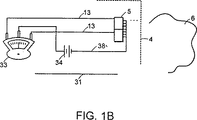
図1Bは、信号分析用の別の電気システムに連結する、図1Aの分光器モジュールの光検出器を示す。
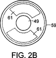
図2Aは、介入デバイスの遠位端に備えられる分光器モジュールの、図2B中の線2A−2Aに沿った、断面図である。
図2Bは、図2Aにおける分光器モジュールの遠位端の断面図である。
図3は、介入デバイス、および介入デバイスの遠位端に備えられる分光器モジュールの概略図である。
図4は、介入デバイスの遠位端に備えられ、その先端部に内包される、図2Aの分光器モジュールの断面図である。
図5は、1つの基板分光器モジュールの断面図であり、モジュールの長手方向に沿った断面図である。
説明
図1Aを参照すると、分光器モジュール1は、互いに、および対象の領域6に近接する光源3および多チャネル光検出器5を含む。対象の領域6は、体内に位置する生命のある組織であり得る。光源3および光検出器5は対象の領域に近接し、それにより、その双方は、介在する空間または材料を最小限に、光エネルギーを効率的に放出および/または連結し得る。光源3は、DC電力線9を介して電力供給または電源7に連結し、光検出器5はバイアス供給線10を介して電源7に連結する。電源7は、高電圧または低電圧いずれかの直流(DC)、適切な周波数の交流(AC)、またはパルスを提供し得る。変調器17を用いて光源を調節するために、AC電力が光源3に提供され得る。または、複雑な波形を有する電流が光源3に供給され得る。AC電力のいくらかを整流するために、光源3における回路にダイオードが設置され得、それにより、ダイオードは検出器5をバイアスするために用いられ得る。開示される実施態様では、計量デバイス19が電源に設置され、その計量デバイス19は、光源3に付与される電力を監視する、および表示するために電流サンプリング回路20を一線に用いる。この構成は、使用中における器具調整を補助するために用いられ得る。
1つ以上の出力線13が、増幅器21およびA−D変換器23を介して、検出器5からマイクロプロセッサ25およびディスプレイ11に延びる。出力線13はノイズピックアップを削減するために遮蔽され得る。検出器5の出力は、増幅器21を介して増幅され、アナログからデジタルへの(A−D、A/D、またはAからD)変換器23に送られる。次いで、デジタル化された信号は、引き続くスペクトル分析のために、マイクロプロセッサ25または他の論理デバイスに送られ得る。別の信号処理システムが図1Bに示される。
ここで図1Bを参照すると、別の信号処理システムはセンタリングスケールメータ33を含む。このメータ33は、光検出器38から延びる共通復帰線38に設置されるDC源34によって駆動される。この別の信号処理システムは、光検出器5の、同時に作動する2つ以上のチャネルによって受け取られる光学的信号の異なる信号振幅を観測するために用いられ得るか、または光検出器5によって受け取られる光エネルギーに対して光源の規格化された出力を観測するために用いられ得る。表示される増幅は、入力信号に対する応答信号の傾斜を決定するために用いられ得るか、または他の、より複雑な機能を実行するために用いられ得る。チャネルの応答特性が時間とともに変化する限りにおいては、単一チャネル光検出器の使用からも等価の操作を得ることができることを、この時点で理解されたい。応答特性を、例えば1つ以上のフィルタを用いることで変化させ得る。単一チャネル光検出器の場合、必要に応じて、2つの信号は連続的に獲得され得る。上述の回路によって提供される機能は、発明の思想および範囲から逸脱することなく、他のまたは追加の電気的、機械的、および/または光学的装置によって達成され得る。
図2Aおよび2Bを参照すると、分光器モジュール41は介入デバイス4の遠位先端部に備えられる。分光器モジュール41はハウジング43内に設置される。ハウジング43は光学的に透明な材料を含む。ハウジング41の口径は、分光器モジュール41およびハウジング43が、カテーテルの様々なルーメン、ならびに血管および非血管道管などの体内のルーメンを通過することを可能にするのに十分な程小さい。例えば、カテーテル4と共に用いられる分光器モジュール41のハウジング43は、最大口径が約0.25インチである。ガイドワイヤサイズのデバイスと共に用いられる分光器モジュール41のハウジング43は、最大口径が約0.081インチである。
分光器モジュール41は、光源3、2つの光検出器61、レンズ47、光増幅器49、および窓55を含む。光源3は半導体ダイオードソースであり、出力端部45がモジュール41の遠位端に面するように搭載される。一般に、光源3は介入デバイス4の中心軸と直線をなす。または、光源3は、その出力端部が介入デバイス4の中心軸を横切る方向に面するように配置され得る。光源3によって発生される光は、組織領域を直接照射し得るか、または組織領域を照射する前に、レンズ47によって集中され得る。レンズ47は光を所望のパターンに集中するように形作られ得るか、または必要に応じて、光を拡散するために用いられ得る。周波数逓信器49は、光出力の周波数を増幅するために、光源3によって発生される光の経路に設置される。周波数逓信器49は、光学的に非線形な基板を含む。光学的に非線形な基板49は、光源3の位置に対して基板49の位置を維持するために、リングホルダー51に合わせてその位置に保持される。または、非線形的基板49は、光学的に透明な接合材料を用いて、光源3の出力端部45に直接接合され得る。光学的に透明な接合材料は、エポキシ、シアノアクリレート、またはケイ酸ナトリウムであり得る。接合材料は、光源5の出力端部45およびその周辺領域に直接備えられ、非線形的基板49は、その接合材料の上に配置され得る。本発明の分光器モジュールでの使用に適切な、光学的に非線形的基板の例は、リン酸二水素カリウム(KH2PO4)すなわちKDP結晶である。光の透過を向上させるために、KDP結晶の少なくとも1つの表面は、1/4波整合層53として機能するフッ化物層によって被覆され得る。窓55は、モジュールを保護するために、分光器モジュール41の遠位端に設置される。窓55は、接着剤57を用いて、介入デバイスの遠位先端部に接合することによって、その位置に維持され得る。好適な実施態様では、窓55は帯域消去フィルタ特性を含み、それは、所定の周波数を有する光出力の通路を許可しながら、光源3によって発生される光の出力周波数を減弱する特性である。フィルタを通過することを許可される光出力はしばしば紫外範囲にあり、特に、約300nmから400nmの波長を有する。そのようなフィルタは一般に入手可能であり、公知である。この種類のフィルタの例は、薄く着色されたガラス、サンドイッチ状に挟まれた染料、および、ダイクロイックフィルタ(dichroic filter)としても公知の、干渉フィルタを含む。または、図4に示される薄く着色されたプラスチックカテーテルシースまたは先端部81などの、別の着色された材料の位置に対して、モジュール41の内部を回転させることによる様々な濾過が用いられ得る。カテーテルシースまたは先端部81は、厚さの変化または局在化する染料に起因して、異なるフィルタ特性を有し得る。
1つ以上の光検出器61およびフィルタ63が非線形的基板49の周囲に備えられ得る(図2B)。光検出器61は、例えば、小型化され、且つ、口径が約0.250インチ以下のデバイスの範囲内に設置され得る、シリコン光ダイオード、電極を備える硫化カドミウムスラブ、電荷が接続されたデバイス、または一般的な任意の光センサであり得る。光検出器61は、対象領域6によって発せられる光の収集を補助するために、角度を有して位置づけられ得る(図2A)。または、光検出器61は、光源3に隣接する平坦な基板上に備えられ得る。対象領域を照射する光信号は、対象領域6と相互作用する結果、変更される。光検出器61は、変更された光信号を検出する。光検出器61は、光源からの発光をも監視し得る。光検出器61は、電力線10を介して、電源7からのエネルギーによって起動される(図1A)。周波数選択検出器61は、光検出器61上にフィルタ63を備えることで作成される。フィルタ63は、光検出器61によって受け取られるエネルギーの1つ以上の周波数帯を減弱する。フィルタ63は、例えば、波長を選択的に許可する帯域通過タイプであり得る。1つのフィルタの具体的な帯域通過は、380nmに中心があり得、別のフィルタは440nmに中心があり得る。信号出力を送達する信号ワイヤ13は、捻られた対のワイヤの形を取り得、または共通の接地経路を共有し得る。信号ワイヤ13は、介入デバイス4の1つ以上のルーメン65内を通され、介入デバイス4の近位端上またはその近傍に位置づけられる適切なコネクタまで延びる。
図3を参照すると、図2の分光器モジュール41は介入デバイス70の遠位端に備えられる。開示される実施態様において、モジュール41はシャフト71の遠位端に取り付けられ、シャフト71は信号ワイヤ9、10、および13を組み込む。シャフト71は、近位端で小さいコネクタ73によって終結する。コネクタ73は、係合するコネクタへの電気的、光学的、および機械的接続を可能にするために整列される1つ以上の接触を有し得る。シャフト71は、また、体内における配置の深さについての制御を可能にするために予め位置決めされ得る、スライド可能なストップ75をも有する。ストップは、コレットリング77を備える継ぎ管であり得、そのコレットリング77は、正ストップを提供するために捻られる場合に緊縮する。シャフト71は、ステンレス鋼ハイポ管、超弾性(ニチノール)管などの管を含み得る。そのようなシャフトの利点は、それらが比較的剛性にとみ、部分的に閉塞した経路内への挿入を可能にすることである。非常に小さいシャフトは金属管から形成され得る。多くの場合、口径が約0.08インチ以上のより大きいシャフトが適当であるが、外径約0.005インチのシャフトが提供され得る。シャフトの長さも数ミリメートルから200センチメートル以上まで変更し得る。シャフト71は、必要に応じて、より可撓性を有する材料から形成され得る。多層に積層された、小さい口径の逆巻きされたワイヤがシャフト材料として用いられ得る。これらのシャフトは、長手方向の可撓性が比較的高く、且つねじれに対する良好な剛性を有し、手動での捻りまたはモータによって、特定の角度を有して設置され得る。他のシャフトは、ポリエチレン、ポリイミド、またはナイロンなどのプラスチックを含み得、1つ以上のルーメンを有し得る。ルーメンは、電気的、光学的、または機械的透過線、または冷却液を担持する。開示される実施態様では、シャフト71は、モジュール41のシャフト71への取り付けおよび取り外しを補助するために、遠位端にネジ山79を有する。取り付けネジ山の可能な使用目的の1つは、一旦モジュール41が体内に位置づけられると、モジュール41をネジ抜きし、取りはずすことによって、シャフト71の端部からモジュール41を解除することであり得る。次いで、管状シャフト71は小さいコネクタ73上をスライドし得、体外に残され得る。モジュール41は、体内からモジュール41を引き抜く前にシャフト71に再接続され得る。
図4を参照すると、図2Aの分光器モジュール41は光学的に透明な先端部81の内部に位置づけられ、先端部81およびモジュール41は介入デバイス80の遠位端に備えられる。先端部81は、ポリスチレンなどのプラスチック、石英などのガラスを含み得、またはスクロースなどの溶解可能な材料から成形される。先端部81は、カテーテル本体83の中央ルーメン84に連結する流体通路82を含む。流体通路82は、水などの連結液をデバイスの先端部またはその近傍に提供するために、或いは染料(墨など)または薬剤(Photofrinなど)を注入するために、或いは流体または組織サンプルを回収するために用いられ得る。先端部81は二次的なフィルタを含み得る。先端部81に対するモジュール41の位置づけは、様々な種類の光学経路の獲得を可能にする。例えば、モジュール41は先端部81内で回転され得、それにより、二次的フィルタは1つ以上の検出器61、または光源3から発せられる光と直線上に並ぶ。
カテーテル本体83は、粘膜組織85内の対象領域にモジュール41を導くために、モジュールをカテーテル83の中央ルーメン84内を通して、その中にモジュール41を組み込み得る。図4に示される実施態様は、操作者が、薬剤注入による組織内の変化、または蛍光染料の選択的取込について監視することを可能にする。先端部81の形状は、粘膜ライニング85の表面から光の鏡面反射の回避を助け、且つ、しばしば強い蛍光を発するバクテリアなどの介入材料の移動を助ける。先端部81は組織材料の実際の除去についての必要性を回避しながら、基本的に、角度の独立性を提供し得る。先端部81が若干その向きを変えられる場合、組織の移動は、その組織を顕著に実際に切り裂くことなく達成される。侵入の深さは、カテーテル83の肩部86を組織に押しつけて設置し、且つカテーテル83に対して先端部81をスライドさせることによって、制御され得る。肩部86を越える先端部81の同一平面または負の隙間から、約1.0ミリメートルまたはより大きい突出状態までの伸張の範囲が、2つの構成要素の間の摩擦係合を用いる場合には、実用的である。シャフト71(図3)およびモジュール41は、必要に応じて、透明エポキシを用いて先端部81に接合され得る。そのような構成の利点は、アセンブリ全体がカテーテル83内においてスライド可能および回転可能に設置され得ることである。カテーテル83の管状形態は、は、例示的なものであるにすぎない。流体を送達するために用いられる多くのカテーテルシースおよび他の介入デバイスは、針、ガイドワイヤ、誘導カテーテル、外套針、イントロデューサ、内視鏡、およびステントを含んで、用いられる。
管またはハウジングは、任意に、透明材料または拡散材料で満たされ得る。光学的に透明な材料の例は、エポキシ、水、および油を含む。拡散材料の例は、粘性の流体中に保たれる特定の物質を含み、硬化するエポキシ、あるいは、様々な解剖学的状態に適合するか、または様々なカテーテル先端部内の形に適合するために可撓性を保持し得る、エラストマー材料などがそれである。
図4の介入デバイスは、機能的要素の全てを1つの基板に組み込むことで、より有用、より安価、またより小さいものに作成され得る。その1つの基板は、介入デバイス、および必要に応じて生命のある組織にはめ込まれるか、取り付けられるか、備えられるか、または埋め込まれ得る。図5では、単一基板のスペクトル分析パッケージ90は、非常にコンパクトな配置で、それらの特徴を用いる。開示される実施態様では、前述の要素は、ドープ処理された積層シリコン基板上に形成される。または、基板91は、エポキシ繊維ガラス樹脂基板上にエッチングされたプリント回路であり得る。発光部分は、基板91の一方の側面に接合される、エッチングされた半導体N材料95およびダイヤモンドヒートシンク97を含む、一体的な発光ダイオード配列93である。基板91の基準表面の下にエッチングされた間隙99は、圧電気光変調器103に接合される鏡101に光エネルギーが導かれることを可能にする。鏡101は、変調器103を面取りし、研磨した後に、その圧電気光変調器103の1部にアルミニウムめっきを施すことによって形成され得る。または、鏡は、ガラス材料からなる約0.150ミリメートル四方で0.010ミリメートル厚の小さいスラブを含み得る。そのスラブは、間隙99内に隙間を持たせるような位置にアクチュエータを配置するために、エポキシ樹脂の薄膜と接合される。圧電気光変調器103の構成は、導電性のエポキシを用いてLead Zirconate−Titinate(PZT)の1つの層を基板91に直接接合し、細密な銅製ワイヤ107を備える電極105を超音波的に溶接するか、またはエポキシ接合することによって達成され得る。次に、電極105は、電気ターミナルポスト(terminal post)109に接合される。ターミナルポスト109は直径約0.030ミリメートル、長さ約0.328ミリメートルであり得、金を被覆した黄銅ワイヤを含み得る。大きいポスト110は基板91のベースに超音波的に溶接され、配向キーである機械的安定器として機能し、また若干大きい電流を担持し得る。
アバランシェ光ダイオード(APD)アレイ121もまた、基板91からエッチングされ、非常に敏感な光検出器として機能する。図5に示される実施態様では、光検出器121は2つのチャネルバージョンを有する。しかし、より多くのチャネルが、以下の構成を単純に繰り返すことによって付加され得る。細いワイヤ107を介してポスト109に個別に接続されるN材料層125上に、酸化シリコン(SiO2)層123を堆積する。空乏層127は、N材料層125と基板91との間に挟まれ、且つポスト110への共通復帰回路の1部としても機能し得る。着色された光フィルタ131は、APDの1つ以上の光感応部分の上に位置づけられ得、それにより、1つのチャネルのスペクトル応答が他のそれと異なる。開示される実施態様において、着色された光フィルタ131は1つのチャネル上に位置づけられる。フィルタは、例えば、ガラス、格子、または染料から形成されるダイクロイックフィルタなどのウェーブフィルタを含み得る。フィルタ131は、暫定的に、酸化シリコン層123上に設置され、光学ポッチング(potting)プラスチック133がアセンブリを覆って成形される間、その位置に保持される。例えば、ポリスチレン、ポリカーボネート、およびメチルメタクリレートなどの材料が、パッケージ90の所望の形状を成形または射出成形するための光学ポッチングプラスチックとして用いられ得る。ウレタンなどの他の材料は、光エネルギーを十分に透過し得、且つ鏡101などの小さいエクスカーションを可能にするのに妥当な弾性を有する限り、鋳型を形成するために用いられ得る。間隙99の周辺の空気スペースは、鏡101近傍および発光ダイオード93の出力端部において必要な屈折率に依って、好適であり得る。これを達成するための方法の1つは、予め成形されたフレームを間隙99にかぶせることであり、それにより、領域内へのポッチング材料の流入が防がれる。フレームは、パッケージ90にも用いられる材料、または融点がより高い材料から射出成形され得る。フレームは、透明エポキシフィルムの薄層の適所に接合され得る。パッケージ90は、パッケージに入る光学的信号またはそこから出る光学的信号の変更を可能にするように形作られ得る。示される実施態様では、鋸状のレンズ135はパッケージ90の表面に成形またはエンボス加工される。この構成の利点は、研磨された鋳型が、必要に応じて、所望の精密な光学表面を形成するために用いられ得ることである。最新技術の射出成形技術、およびポリスチレンなどの比較的粘性の低い熱可塑性は、表面上における制御可能な寸法およびステップ高を備えた、非常に精巧な特徴の形成を可能にする。表面特徴の寸法は、約0.005ミリメートルの範囲内であり得る。0.005ミリメートルより小さい、より一層精巧な特徴は、圧力およびフォトエッチングされたマスタ(master)を用いてエンボス加工され得、それによりIR光、可視光、およびUV光を回折し得るバイナリ光学工程、ホログラム、または格子がパッケージ90の表面上に直接形成され得る。表面上、またはアセンブリ内におけるそのような特徴の形成は、高価な光学構成要素およびそれらのホルダの追加の必要性を回避する。従来の湾曲レンズ137は、必要に応じて光エネルギーを集めるために、パッケージ90の表面上に形成される。従来の湾曲レンズ137もまた、成形操作中に表面に成形され得る。格子は、1つ以上の、周波数選択能力を提供する検出器にわたって光を分散し得る。
本発明による分光器モジュールは、光源および光検出器を、スペクトル分析下の組織領域の近くに配置するように設計される。スペクトル分析を使用する組織の性質決定は、光源から発せられた光が組織と相互作用し、光が変化するという知見に基づく。吸収、散乱、および他のエネルギー損失は、光が組織と相互作用するときに生じる。しかし、種々の組織の種類は、異なる吸収および反射特性を有する。したがって、組織は、スペクトル分析を使用して特徴づけられ得る。しかし、これらの相互作用現象はまた、達成され得る光の侵入の深さを制限する。したがって、光源が対象の組織の近くに配置されない場合、異質な因子によるエネルギー損失は深刻になり得る。本発明は、光源および光検出器を対象の組織の近くに配置する手段を提供し、効率的な操作が達成され得る。したがって、発明の分光器モジュールは、不必要な光損失を排除し、光検出器が組織との相互作用によって起こされる光の変化を検出することを可能にする。
一般に、分析下の被験体との相互作用によって変化された光信号を検出し得え、そして介入デバイス中にうまく合うように十分に小さく作成され得る任意のタイプの光検出器が、本発明に従って使用され得る。例えば、電荷結合素子(CCD)センサが、エネルギー生成源のまわりに円周をなすように配置され、そして信号ワイヤを介して接続され得る。あるいは、シリコン光ダイオード、硫化カドミニウムセル、またはシンチレーション検出器が、光波エネルギーの戻る部分が捕捉されそして測定されるように配置され得る。CCD型センサの場合、そのようなセンサの1つだけが有用な信号を得,そして測定するために必要であり得るが、多くのそのようなデバイスがまた非常に小さい領域に組み込まれ得る。あるいは、2つ以上のセンサが本発明に従って使用され得る。複数のセンサを使用する利点は、それらがフィルタを変化させる必要を排除することである。例えば、2つの波長の相対強度が特定の組織の種類または状態を示す傾斜を生成するように、フィルタxが青色光波を通すように配置され得、同時にフィルタyが赤色光波を通すように配置され得る。
介入デバイスに配置され得る任意の光源が本発明にしたがって使用され得る。タングステンフィラメント光源などの普通の白熱光源であってその上に適切なフィルタを配置されたもの、アークランプ、水銀蒸気(vapor)ランプ、キセノンフラッシュランプ、種々のガスを充填されたガス放電ランプ、金属蒸気、可視光およびUV光を生成し得る音駆動型音ルミネセンス源、X線、超高エネルギー(SHF)のグン(Gunn)ダイオード源、発光ダイオード、ならびに長波長または短波長で長持続時間または短持続時間出力のいずれでも可能な他の光源が本発明に使用され得る。
可能な光源システムおよび光検出構成は、2つの共通に所有される米国仮特許出願、すなわち米国仮特許出願第60/033,333号および米国仮特許出願第60/033,335号において記載される。これらの開示、およびこれらの暫定出願の1つまたは両方を基礎に変換された任意の正規の米国特許出願は、本明細書中で参考として援用される。一般に、光源システムおよび光検出システムは、例えば、コスト、複雑性、小型化、および治療特性を含む種々の因子に基づいて、本発明による使用のために選択される。
本発明の分光器モジュールの形状は、モジュールと対象の領域との接触または生成された光の対象の領域への光学的透過を最適化するために適切な任意の形態でよい。可能な形状は、例えば、凹状、階段状、円筒状、先端のとがった形状、円錐形状、凸状、および半球状である。加えて、モジュールの外側または内側表面は、光透過特性を増強するためか、またはマイクロレンズ、バイナリー光学工程、または波長フィルタが提供されるために、特定の材料でコーティングされ得る。
本発明は、光源システムおよび光検出器システムの両方の点で説明されたが、光源システムおよび検出器システムが単独で、必要が生じる特定の状況において使用され得ることが当業者に理解されるべきである。。さらに、光源または検出器のいずれかは、非光生成または非受光デバイスで置き換えられ得る。実施例は、より長い波長で分光測定し得る高周波数生成および受信システム、およびx線分光測定し得るx線生成および受光システムを含む。一般に、本発明の基本的な特徴のいくつかは、局所的エネルギー源を生成する工程、エネルギー源を組織の選択された領域へ付与する工程、組織の選択された領域との相互作用で変化されたエネルギーを収集する工程を含む。好ましくは、収集されたエネルギー信号が組織を性質決定するために分析され、そしてその結果が操作者またはユーザーに示される。
本明細書中に記載されるものの変形、改変、および他の実装は、請求されるような発明の精神および範囲を逸脱せずに当業者に思い付かれる。したがって、本発明は、先行の例示的説明によってではなく、以下の請求項の精神および範囲によって規定されるべきである。 Citation to related application
The present invention is based on US Provisional Patent Application No. 60 / 033,334, filed Nov. 21, 1996.
Technical field
The present invention relates to a spectroscope, and more particularly to a miniature spectroscope that is placed in the body to determine tissue properties.
Background information
Spectral analysis of living tissue can be used to detect various forms of cancer and other types of diseases. In spectral analysis, light illuminates a tissue region under examination and an optical property of the tissue region illuminated by a photodetector is detected. Detection is performed by measuring light energy in a predetermined frequency and amplitude range that has been altered by interacting with the tissue region. Optical properties include absorption, emission, fluorescence, frequency and time domain response, and other electromagnetic responses to various materials injected into the tissue region. Diseased tissue can be identified by comparing the resulting spectrum with the spectrum of normal tissue obtained under identically controlled conditions.
Currently available spectral analysis devices for tissue characterization include a night vision sensing system with a filter configured to be used with an endoscope and a multi-channel fiber optic delivery system. A multi-channel fiber optic delivery system typically includes a light source, an optical conduit, an optical applicator and receiver, a second optical conduit, a spectrometer, and a display unit. These systems are very expensive, tend to require an accompanying large electrical system, and tend to be so complex that operational training is required.
Optical fibers used as optical conduits in multi-channel fiber optic delivery systems are a design challenge. In order to transfer the appropriate amount of light energy from the light source to the tissue region in the body, a large amount of optical fiber needs to be included in the interventional device. However, interventional devices such as catheters do not include a lot of space, and higher quality optical fibers that require less space are expensive.
Optical fibers also lack the mechanical properties necessary to be used with interventional devices. Optical fibers can break when bent, and their stiffness is relatively high compared to conventional catheter materials. Thus, it is difficult to design a flexible tip for a catheter that includes an optical fiber, and the overall flexibility of an interventional device that includes an optical fiber is limited.
In addition, optical fibers require expensive termination connectors and need to be properly coupled to obtain adequate light processing capabilities. The signal efficiency of an optical fiber-based device is highly dependent on the device's ability to couple enough light into the optical fiber at the desired wavelength. For spectral analysis, a filtered broadband light source is preferred over a laser light source in terms of cost and frequency versatility. However, it is a challenge to efficiently couple light from a lamp source into a small diameter optical fiber. Although laser light is more easily coupled into optical fibers, laser light sources are generally more expensive, can only obtain light at some selected wavelengths, and are managed by more important regulations than other light sources It becomes the object of. Furthermore, the light emitted from the object illuminated by the laser light tends to be weak and suffers from all of the loss mechanisms and inefficiencies that are problems with laser systems.
The need to provide additional hardware, such as connectors and couplers, and one or more optical conduits along the entire length of the interventional device makes conventional devices used for spectral analysis relatively expensive, inconvenient, and roughly Make it impractical.
Summary of the Invention
In one aspect, the invention presents a miniature spectrometer used for spectral analysis. The spectrograph includes a light source and a photodetector disposed within the body, thereby eliminating the need for an optical conduit for delivering optical signals to or from tissue within the body. The miniature spectrometer includes a light source and one or more photodetectors. The light source illuminates the tissue region and the photodetector detects the optical characteristics of the illuminated tissue by measuring the altered optical signal. The photodetector converts the optical signal into an electrical signal so that one or more electrical wires disposed within the interventional device can deliver the electrical signal from the tissue to a signal display or microprocessor. .
Embodiments of this aspect of the invention include the following features. The light source and photodetector are activated by an external power source via electrical wires. In another embodiment, an optically clear tip encloses the spectrometer. The tip is shaped to optimize tissue contact and optical transmission. A tip containing the spectroscope is provided at the distal end of the interventional device. The tip can be coated with a material to improve light transmission. The tip may include at least one fluid passage for delivering fluid to the tissue region, the fluid passage being coupled to a lumen in the interventional device. In one disclosed embodiment, the inventive spectrometer includes a light source and a photodetector formed on a single substrate. The light source can be a light emitting diode and the photodetector can be a multi-channel photodiode. Both devices are formed on a silicon substrate. The photodetector may include multiple channels to detect multi-wavelength emission.
In another aspect, the invention presents a method for tissue characterization. According to the method, a spectrometer is provided that includes a light source and a plurality of photodetectors. The spectroscope is placed in the vicinity of the tissue region to be characterized in the body. The light source and detector are connected to a power source via electrical wires. The activated light source generates light and illuminates the tissue region. The detector measures a modified optical signal as a result of interaction with the tissue region. The photodetector converts the received optical signal into an electrical signal. In one embodiment for this aspect of the invention, the optically clear tip encloses the spectrometer and is positioned near the distal end of the interventional probe. The method can further include rotating the spectrometer relative to the tip. The rotation adjusts the optical properties of the light transmitted to illuminate the tissue.
The foregoing and other objects, aspects, features and advantages of the invention will become more apparent from the following description and appended claims.
[Brief description of the drawings]
In the drawings, like reference characters generally refer to the same parts throughout the different views. Also, the drawings are not necessarily drawn to scale, but are emphasized generally to illustrate the principles of the invention.
FIG. 1A is a block diagram of a system for spectral analysis that includes a spectrometer module coupled to external components.
FIG. 1B shows the photodetector of the spectrometer module of FIG. 1A coupled to another electrical system for signal analysis.
FIG. 2A is a cross-sectional view of the spectrometer module provided at the distal end of the interventional device, taken along line 2A-2A in FIG. 2B.
2B is a cross-sectional view of the distal end of the spectrometer module in FIG. 2A.
FIG. 3 is a schematic diagram of the interventional device and the spectroscopic module provided at the distal end of the interventional device.
FIG. 4 is a cross-sectional view of the spectrometer module of FIG. 2A provided at the distal end of the interventional device and contained within the tip thereof.
FIG. 5 is a cross-sectional view of one substrate spectrometer module, and is a cross-sectional view along the longitudinal direction of the module.
Explanation
Referring to FIG. 1A, the spectrometer module 1 includes a light source 3 and a
One or
Referring now to FIG. 1B, another signal processing system includes a centering scale meter 33. The meter 33 is driven by a
With reference to FIGS. 2A and 2B, the
The
One or
Referring to FIG. 3, the
Referring to FIG. 4, the
The
The tube or housing can optionally be filled with a transparent or diffusing material. Examples of optically transparent materials include epoxy, water, and oil. Examples of diffusing materials include certain substances that are kept in viscous fluids, to cure epoxies, or to adapt to various anatomical conditions or shapes within various catheter tips For example, an elastomer material that can retain flexibility.
The interventional device of FIG. 4 can be made more useful, less expensive, and smaller by incorporating all of the functional elements into one substrate. The one substrate may be fitted, attached, provided, or implanted in the interventional device, and in living tissue as required. In FIG. 5, a single substrate
An avalanche photodiode (APD)
The spectrometer module according to the present invention is designed to place the light source and photodetector near the tissue region under spectral analysis. Tissue characterization using spectral analysis is based on the finding that light emitted from a light source interacts with the tissue and the light changes. Absorption, scattering, and other energy losses occur when light interacts with tissue. However, different tissue types have different absorption and reflection characteristics. Thus, the tissue can be characterized using spectral analysis. However, these interaction phenomena also limit the depth of light penetration that can be achieved. Thus, if the light source is not placed close to the tissue of interest, energy loss due to extraneous factors can be severe. The present invention provides a means for positioning the light source and photodetector near the tissue of interest so that efficient operation can be achieved. Thus, the inventive spectrometer module eliminates unnecessary light loss and allows the photodetector to detect light changes caused by interaction with tissue.
In general, any type of photodetector that can detect an optical signal altered by interaction with a subject under analysis and can be made small enough to fit well in an interventional device is in accordance with the present invention. Can be used. For example, a charge coupled device (CCD) sensor can be placed around the energy generating source and connected via a signal wire. Alternatively, a silicon photodiode, cadmium sulfide cell, or scintillation detector can be positioned so that the returning portion of the light wave energy is captured and measured. In the case of a CCD type sensor, only one such sensor may be necessary to obtain and measure a useful signal, but many such devices can also be incorporated in a very small area. Alternatively, more than one sensor can be used in accordance with the present invention. The advantage of using multiple sensors is that they eliminate the need to change the filter. For example, filter x can be arranged to pass blue light waves, while filter y is arranged to pass red light waves, such that the relative intensity of the two wavelengths produces a slope indicative of a particular tissue type or condition. obtain.
Any light source that can be placed on the interventional device can be used in accordance with the present invention. An ordinary incandescent light source such as a tungsten filament light source with an appropriate filter disposed thereon, an arc lamp, a mercury vapor (lamp) lamp, a xenon flash lamp, a gas discharge lamp filled with various gases, a metal Sound-driven sonoluminescence sources capable of producing vapor, visible light and UV light, X-rays, very high energy (SHF) Gunn diode sources, light emitting diodes and long or short wavelength long duration or Other light sources capable of any short duration output can be used in the present invention.
Possible light source systems and light detection configurations are described in two commonly owned US provisional patent applications, namely US provisional patent application 60 / 033,333 and US provisional patent application 60 / 033,335. . These disclosures, and any regular US patent application converted on the basis of one or both of these provisional applications, are hereby incorporated by reference. In general, light source systems and light detection systems are selected for use according to the present invention based on various factors including, for example, cost, complexity, miniaturization, and therapeutic properties.
The shape of the spectrometer module of the present invention may be in any form suitable for optimizing optical contact of the module with the area of interest or optical transmission of the generated light into the area of interest. Possible shapes are, for example, concave, stepped, cylindrical, pointed, conical, convex and hemispherical. In addition, the outer or inner surface of the module can be coated with specific materials to enhance light transmission properties or to provide microlenses, binary optical processes, or wavelength filters.
Although the present invention has been described in terms of both a light source system and a light detector system, it should be understood by those skilled in the art that the light source system and the detector system can be used alone in specific situations where the need arises. It is. . Further, either the light source or the detector can be replaced with a non-light generating or non-light receiving device. Examples include a high frequency generation and reception system that can perform spectroscopic measurements at longer wavelengths, and an x-ray generation and reception system that can perform x-ray spectroscopic measurements. In general, some of the basic features of the present invention are altered by generating a local energy source, applying an energy source to a selected region of tissue, and interacting with a selected region of tissue. Collecting the collected energy. Preferably, the collected energy signal is analyzed to characterize the tissue and the results are presented to the operator or user.
Variations, modifications, and other implementations of what is described herein will occur to those skilled in the art without departing from the spirit and scope of the invention as claimed. Accordingly, the invention is to be defined not by the preceding illustrative description but instead by the spirit and scope of the following claims.
Claims (24)
角度をなす表面を有し、かつ該分光器を封入する光学的に透明な先端であって、該先端が組織接触および光学的透過を最適にするための形状を有する、先端、
ここで、該分光器が先端にたいして回転するように適応され、それによって該光源によって生成された光の光学的特性を調節し;および
分光器を組織へ送達するための介入デバイス、
を包含する組織分光デバイス。A spectroscope comprising a light source for illuminating tissue and a plurality of photodetectors for detecting optical properties of the illuminated tissue, wherein the plurality of photodetectors convert the optical signals into electrical signals A spectrometer adapted to convert, wherein the light source and the plurality of photodetectors are adapted to be placed together in a living body;
An optically transparent tip having an angled surface and encapsulating the spectrometer, the tip having a shape to optimize tissue contact and optical transmission;
Wherein the spectrometer is adapted to rotate relative to the tip, thereby adjusting the optical properties of the light generated by the light source; and an interventional device for delivering the spectrometer to the tissue;
Including a tissue spectroscopic device.
ここで、該分光デバイスが、患者の内部の特徴づける患者の組織の近くに配置されるよう適合され;
ここで、該分光器が、該光源によって生成された該光の光学的特性を調節するために該先端にたいして回転するよう適合され;そして
該照射された組織の光学的特性が測定され得る、組織を特徴づけるための組織分光デバイス。(I) a spectroscope comprising a light source and a plurality of photodetectors adapted to convert an optical signal into an electrical signal; (ii) an angled surface, and optimal tissue contact and optical transmission An optically transparent tip that encapsulates the spectrometer, and (iii) an interventional device for delivery to the tissue that characterizes the spectrometer;
Wherein the spectroscopic device is adapted to be placed near the patient tissue characterizing the interior of the patient;
Wherein the spectrometer is adapted to rotate relative to the tip to adjust the optical properties of the light generated by the light source; and the optical properties of the irradiated tissue can be measured Tissue spectroscopic device for characterizing.
Applications Claiming Priority (5)
| Application Number | Priority Date | Filing Date | Title |
|---|---|---|---|
| US3333496P | 1996-11-21 | 1996-11-21 | |
| US60/033,334 | 1996-11-21 | ||
| US08/898,604 US6119031A (en) | 1996-11-21 | 1997-07-22 | Miniature spectrometer |
| US08/898,604 | 1997-07-22 | ||
| PCT/US1997/020324 WO1998022805A1 (en) | 1996-11-21 | 1997-11-07 | Miniature spectrometer |
Publications (3)
| Publication Number | Publication Date |
|---|---|
| JP2001504371A JP2001504371A (en) | 2001-04-03 |
| JP2001504371A5 JP2001504371A5 (en) | 2005-07-14 |
| JP4380798B2 true JP4380798B2 (en) | 2009-12-09 |
Family
ID=26709571
Family Applications (1)
| Application Number | Title | Priority Date | Filing Date |
|---|---|---|---|
| JP52369698A Expired - Fee Related JP4380798B2 (en) | 1996-11-21 | 1997-11-07 | Small spectroscope |
Country Status (6)
| Country | Link |
|---|---|
| US (4) | US6119031A (en) |
| EP (1) | EP0939894B1 (en) |
| JP (1) | JP4380798B2 (en) |
| AU (1) | AU5172998A (en) |
| DE (1) | DE69737478T2 (en) |
| WO (1) | WO1998022805A1 (en) |
Families Citing this family (152)
| Publication number | Priority date | Publication date | Assignee | Title |
|---|---|---|---|---|
| US6119031A (en) | 1996-11-21 | 2000-09-12 | Boston Scientific Corporation | Miniature spectrometer |
| US6826422B1 (en) | 1997-01-13 | 2004-11-30 | Medispectra, Inc. | Spectral volume microprobe arrays |
| US6441943B1 (en) * | 1997-04-02 | 2002-08-27 | Gentex Corporation | Indicators and illuminators using a semiconductor radiation emitter package |
| US6324418B1 (en) * | 1997-09-29 | 2001-11-27 | Boston Scientific Corporation | Portable tissue spectroscopy apparatus and method |
| US5984861A (en) * | 1997-09-29 | 1999-11-16 | Boston Scientific Corporation | Endofluorescence imaging module for an endoscope |
| US6238348B1 (en) * | 1997-07-22 | 2001-05-29 | Scimed Life Systems, Inc. | Miniature spectrometer system and method |
| US7637948B2 (en) | 1997-10-10 | 2009-12-29 | Senorx, Inc. | Tissue marking implant |
| US8668737B2 (en) | 1997-10-10 | 2014-03-11 | Senorx, Inc. | Tissue marking implant |
| WO1999018844A1 (en) * | 1997-10-10 | 1999-04-22 | Boston Scientific Corporation | Miniature spectrometer system |
| US6289229B1 (en) * | 1998-01-20 | 2001-09-11 | Scimed Life Systems, Inc. | Readable probe array for in vivo use |
| US6922576B2 (en) * | 1998-06-19 | 2005-07-26 | Becton, Dickinson And Company | Micro optical sensor device |
| US6444970B1 (en) | 1998-06-26 | 2002-09-03 | Scimed Life Systems, Inc. | Miniature low-noise photodiode system |
| US6535753B1 (en) * | 1998-08-20 | 2003-03-18 | Microsense International, Llc | Micro-invasive method for painless detection of analytes in extra-cellular space |
| US6197257B1 (en) * | 1998-08-20 | 2001-03-06 | Microsense Of St. Louis, Llc | Micro sensor device |
| WO2000036973A1 (en) * | 1998-12-23 | 2000-06-29 | Medispectra, Inc. | Optical methods and systems for cervical screening |
| US6411838B1 (en) | 1998-12-23 | 2002-06-25 | Medispectra, Inc. | Systems and methods for optical examination of samples |
| US7524289B2 (en) * | 1999-01-25 | 2009-04-28 | Lenker Jay A | Resolution optical and ultrasound devices for imaging and treatment of body lumens |
| US6592526B1 (en) * | 1999-01-25 | 2003-07-15 | Jay Alan Lenker | Resolution ultrasound devices for imaging and treatment of body lumens |
| US6725083B1 (en) | 1999-02-02 | 2004-04-20 | Senorx, Inc. | Tissue site markers for in VIVO imaging |
| US20090030309A1 (en) | 2007-07-26 | 2009-01-29 | Senorx, Inc. | Deployment of polysaccharide markers |
| US7983734B2 (en) | 2003-05-23 | 2011-07-19 | Senorx, Inc. | Fibrous marker and intracorporeal delivery thereof |
| US9820824B2 (en) | 1999-02-02 | 2017-11-21 | Senorx, Inc. | Deployment of polysaccharide markers for treating a site within a patent |
| US6862470B2 (en) | 1999-02-02 | 2005-03-01 | Senorx, Inc. | Cavity-filling biopsy site markers |
| US7651505B2 (en) | 2002-06-17 | 2010-01-26 | Senorx, Inc. | Plugged tip delivery for marker placement |
| US8498693B2 (en) | 1999-02-02 | 2013-07-30 | Senorx, Inc. | Intracorporeal marker and marker delivery device |
| US8361082B2 (en) | 1999-02-02 | 2013-01-29 | Senorx, Inc. | Marker delivery device with releasable plug |
| US6575991B1 (en) * | 1999-06-17 | 2003-06-10 | Inrad, Inc. | Apparatus for the percutaneous marking of a lesion |
| US7373197B2 (en) * | 2000-03-03 | 2008-05-13 | Intramedical Imaging, Llc | Methods and devices to expand applications of intraoperative radiation probes |
| AU2001255522A1 (en) | 2000-04-20 | 2001-11-07 | Greatbio Technologies, Inc. | Mri-resistant implantable device |
| US8527046B2 (en) | 2000-04-20 | 2013-09-03 | Medtronic, Inc. | MRI-compatible implantable device |
| WO2002033385A2 (en) * | 2000-10-19 | 2002-04-25 | Motorola, Inc. | Biochip excitation and analysis structure |
| CA2429127A1 (en) * | 2000-11-09 | 2002-05-16 | Sicel Technologies, Inc. | In vivo detection of biomolecule concentrations using fluorescent tags |
| EA200300574A1 (en) * | 2000-11-16 | 2004-06-24 | Кэмилийен Медикал Инновейшн Лтд. | SYSTEM FOR DIAGNOSTIC EARS |
| ES2409758T3 (en) | 2000-11-20 | 2013-06-27 | Senorx, Inc. | Tissue site markers for in vivo imaging |
| US6657197B2 (en) * | 2000-12-22 | 2003-12-02 | Honeywell International Inc. | Small profile spectrometer |
| DE10203720B4 (en) * | 2001-02-02 | 2012-11-22 | Nippon Telegraph And Telephone Corp. | Blood flow meter and sensor part of the blood flow meter |
| US20020116029A1 (en) | 2001-02-20 | 2002-08-22 | Victor Miller | MRI-compatible pacemaker with power carrying photonic catheter and isolated pulse generating electronics providing VOO functionality |
| US6829509B1 (en) | 2001-02-20 | 2004-12-07 | Biophan Technologies, Inc. | Electromagnetic interference immune tissue invasive system |
| US6488704B1 (en) * | 2001-05-07 | 2002-12-03 | Biomed Solutions, Llc | Implantable particle measuring apparatus |
| US6793642B2 (en) * | 2001-05-07 | 2004-09-21 | Biomed Solutions, Llc | Flow cytometer |
| US6898451B2 (en) * | 2001-03-21 | 2005-05-24 | Minformed, L.L.C. | Non-invasive blood analyte measuring system and method utilizing optical absorption |
| US20040225326A1 (en) * | 2001-05-07 | 2004-11-11 | Weiner Mike L. | Apparatus for the detection of restenosis |
| US6654630B2 (en) * | 2001-05-31 | 2003-11-25 | Infraredx, Inc. | Apparatus and method for the optical imaging of tissue samples |
| US6731979B2 (en) | 2001-08-30 | 2004-05-04 | Biophan Technologies Inc. | Pulse width cardiac pacing apparatus |
| WO2003020103A2 (en) * | 2001-09-04 | 2003-03-13 | Amit Technology Science & Medicine Ltd. | Method of and device for therapeutic illumination of internal organs and tissues |
| JP2003102672A (en) * | 2001-10-01 | 2003-04-08 | Japan Science & Technology Corp | Method and device for automatically detecting, treating, and collecting objective site of lesion or the like |
| AT412695B (en) * | 2001-11-20 | 2005-05-25 | Efkon Ag | INFRARED (IR) TRANSMISSION DEVICE |
| TWI293363B (en) | 2001-12-11 | 2008-02-11 | Sensors For Med & Science Inc | High performance fluorescent optical sensor |
| US8423110B2 (en) * | 2002-01-09 | 2013-04-16 | Boston Scientific Scimed, Inc. | Imaging device and related methods |
| US6968236B2 (en) * | 2002-01-28 | 2005-11-22 | Biophan Technologies, Inc. | Ceramic cardiac electrodes |
| US8504128B2 (en) * | 2002-03-08 | 2013-08-06 | Glt Acquisition Corp. | Method and apparatus for coupling a channeled sample probe to tissue |
| US8718738B2 (en) | 2002-03-08 | 2014-05-06 | Glt Acquisition Corp. | Method and apparatus for coupling a sample probe with a sample site |
| US20090318786A1 (en) * | 2002-03-08 | 2009-12-24 | Blank Thomas B | Channeled tissue sample probe method and apparatus |
| CA2479841C (en) * | 2002-03-22 | 2012-03-13 | Ethicon Endo-Surgery, Inc. | An integrated visualization system |
| US8131332B2 (en) * | 2002-04-04 | 2012-03-06 | Veralight, Inc. | Determination of a measure of a glycation end-product or disease state using tissue fluorescence of various sites |
| US20070015981A1 (en) * | 2003-08-29 | 2007-01-18 | Benaron David A | Device and methods for the detection of locally-weighted tissue ischemia |
| US6711426B2 (en) * | 2002-04-09 | 2004-03-23 | Spectros Corporation | Spectroscopy illuminator with improved delivery efficiency for high optical density and reduced thermal load |
| US20080009689A1 (en) * | 2002-04-09 | 2008-01-10 | Benaron David A | Difference-weighted somatic spectroscopy |
| US6711440B2 (en) | 2002-04-11 | 2004-03-23 | Biophan Technologies, Inc. | MRI-compatible medical device with passive generation of optical sensing signals |
| US6725092B2 (en) | 2002-04-25 | 2004-04-20 | Biophan Technologies, Inc. | Electromagnetic radiation immune medical assist device adapter |
| AU2003240529A1 (en) | 2002-06-04 | 2003-12-19 | Biophan Technologies, Inc. | Nuclear magnetic resonance spectrometer assembly |
| US7672713B2 (en) * | 2002-06-19 | 2010-03-02 | Infraredx, Inc. | Multi-channel catheter tip |
| US6818903B2 (en) | 2002-07-09 | 2004-11-16 | Medispectra, Inc. | Method and apparatus for identifying spectral artifacts |
| US6768918B2 (en) | 2002-07-10 | 2004-07-27 | Medispectra, Inc. | Fluorescent fiberoptic probe for tissue health discrimination and method of use thereof |
| US6925322B2 (en) * | 2002-07-25 | 2005-08-02 | Biophan Technologies, Inc. | Optical MRI catheter system |
| US7535935B2 (en) * | 2002-09-27 | 2009-05-19 | Infraredx, Inc. | Spectroscopic catheter system with widely tunable source and method of operation |
| DE10249674B4 (en) * | 2002-10-24 | 2014-12-24 | Carl Zeiss Meditec Ag | Surgical instrument for cutting, ablating or aspirating material in an operating area |
| US20060036158A1 (en) | 2003-11-17 | 2006-02-16 | Inrad, Inc. | Self-contained, self-piercing, side-expelling marking apparatus |
| US20050154277A1 (en) * | 2002-12-31 | 2005-07-14 | Jing Tang | Apparatus and methods of using built-in micro-spectroscopy micro-biosensors and specimen collection system for a wireless capsule in a biological body in vivo |
| US20040193023A1 (en) * | 2003-03-28 | 2004-09-30 | Aris Mardirossian | System, method and apparatus for monitoring recording and reporting physiological data |
| US7877133B2 (en) | 2003-05-23 | 2011-01-25 | Senorx, Inc. | Marker or filler forming fluid |
| DE10349839B4 (en) * | 2003-10-25 | 2006-05-18 | Hbw-Gubesch Kunststoff-Engineering Gmbh | Electrical component with a transparent plastic housing |
| US20050273002A1 (en) | 2004-06-04 | 2005-12-08 | Goosen Ryan L | Multi-mode imaging marker |
| US9392961B2 (en) | 2003-12-17 | 2016-07-19 | Check-Cap Ltd. | Intra-lumen polyp detection |
| EP1694207B1 (en) * | 2003-12-17 | 2011-07-27 | Check-Cap Ltd. | Intra-lumen polyp detection |
| WO2008096358A2 (en) | 2007-02-06 | 2008-08-14 | Yoav Kimchy | Intra-lumen polyp detection |
| US20050203419A1 (en) * | 2004-02-24 | 2005-09-15 | Nirmala Ramanujam | Side-firing probe for performing optical spectroscopy during core needle biopsy |
| JP2005278762A (en) * | 2004-03-29 | 2005-10-13 | Fujinon Corp | Centesis type probe for endoscope |
| US7268871B2 (en) * | 2004-08-12 | 2007-09-11 | Datacolor Holding Ag | Measuring head for planar measurement of a sample |
| US8419656B2 (en) | 2004-11-22 | 2013-04-16 | Bard Peripheral Vascular, Inc. | Post decompression marker introducer system |
| US8070767B2 (en) * | 2005-01-28 | 2011-12-06 | Tyco Healthcare Group Lp | Optical penetrating adapter for surgical portal |
| US7470230B2 (en) | 2005-03-31 | 2008-12-30 | Tyco Healthcare Group Lp | Optical obturator |
| US10357328B2 (en) | 2005-04-20 | 2019-07-23 | Bard Peripheral Vascular, Inc. and Bard Shannon Limited | Marking device with retractable cannula |
| US7813778B2 (en) * | 2005-07-29 | 2010-10-12 | Spectros Corporation | Implantable tissue ischemia sensor |
| US8052658B2 (en) | 2005-10-07 | 2011-11-08 | Bard Peripheral Vascular, Inc. | Drug-eluting tissue marker |
| US9168383B2 (en) | 2005-10-14 | 2015-10-27 | Pacesetter, Inc. | Leadless cardiac pacemaker with conducted communication |
| EP1948296B2 (en) | 2005-10-14 | 2017-10-11 | Pacesetter, Inc. | Leadless cardiac pacemaker and system |
| NL1031588C2 (en) | 2006-04-13 | 2007-10-19 | D O R C Dutch Ophthalmic Res C | Eye surgical instrument. |
| US8472111B2 (en) * | 2006-06-13 | 2013-06-25 | The Arizona Board Of Regents On Behalf Of The University Of Arizona | Apparatus and method for deep ultraviolet optical microscopy |
| WO2007147058A2 (en) * | 2006-06-14 | 2007-12-21 | Cornova, Inc. | Method and apparatus for identifying and treating myocardial infarction |
| ES2443526T3 (en) | 2006-10-23 | 2014-02-19 | C.R. Bard, Inc. | Breast marker |
| EP2109409B1 (en) | 2006-12-12 | 2018-09-05 | C.R.Bard, Inc. | Multiple imaging mode tissue marker |
| US8401622B2 (en) | 2006-12-18 | 2013-03-19 | C. R. Bard, Inc. | Biopsy marker with in situ-generated imaging properties |
| WO2008113024A1 (en) * | 2007-03-14 | 2008-09-18 | Spectros Corporation | Metabolism-or biochemical-based anti-spoofing biometrics devices, systems, and methods |
| US7711412B2 (en) * | 2007-05-23 | 2010-05-04 | Ethicon Endo-Surgery, Inc. | Mucosal tissue illuminator and method for use |
| AU2008202266B2 (en) * | 2007-06-01 | 2013-09-12 | Covidien Lp | Obturator tips |
| JP2010540037A (en) * | 2007-09-20 | 2010-12-24 | ナノスティム インコーポレイテッド | Leadless cardiac pacemaker with secondary fixation capability |
| US20100298715A1 (en) * | 2007-09-26 | 2010-11-25 | Holger Jungmann | Method and measuring instrument for collecting spectrometric test signals from living tissue |
| SE531527C2 (en) * | 2007-10-01 | 2009-05-12 | Bioresonator Ab | Method and apparatus for unaffected material examination |
| US7817274B2 (en) | 2007-10-05 | 2010-10-19 | Jingyun Zhang | Compact spectrometer |
| WO2009050667A1 (en) * | 2007-10-18 | 2009-04-23 | Koninklijke Philips Electronics N.V. | Tumor demarcation using targeted fluorescent probe and photonic needle |
| US8345226B2 (en) | 2007-11-30 | 2013-01-01 | Jingyun Zhang | Spectrometers miniaturized for working with cellular phones and other portable electronic devices |
| WO2009099767A2 (en) | 2008-01-31 | 2009-08-13 | C.R. Bard, Inc. | Biopsy tissue marker |
| US9042967B2 (en) | 2008-05-20 | 2015-05-26 | University Health Network | Device and method for wound imaging and monitoring |
| US8577431B2 (en) | 2008-07-03 | 2013-11-05 | Cercacor Laboratories, Inc. | Noise shielding for a noninvasive device |
| US8203704B2 (en) | 2008-08-04 | 2012-06-19 | Cercacor Laboratories, Inc. | Multi-stream sensor for noninvasive measurement of blood constituents |
| US20100069760A1 (en) * | 2008-09-17 | 2010-03-18 | Cornova, Inc. | Methods and apparatus for analyzing and locally treating a body lumen |
| US9327061B2 (en) | 2008-09-23 | 2016-05-03 | Senorx, Inc. | Porous bioabsorbable implant |
| CN101721194B (en) * | 2008-10-14 | 2011-11-09 | 鸿富锦精密工业(深圳)有限公司 | Capsule endoscope and method for manufacturing lenses thereof |
| AU2008365906B2 (en) | 2008-12-30 | 2015-01-22 | C.R. Bard Inc. | Marker delivery device for tissue marker placement |
| WO2010088687A1 (en) | 2009-02-02 | 2010-08-05 | Nanostim, Inc. | Leadless cardiac pacemaker with secondary fixation capability |
| US8688183B2 (en) | 2009-09-03 | 2014-04-01 | Ceracor Laboratories, Inc. | Emitter driver for noninvasive patient monitor |
| US20110077708A1 (en) * | 2009-09-28 | 2011-03-31 | Alan Ostroff | MRI Compatible Leadless Cardiac Pacemaker |
| CN102596044A (en) * | 2009-09-29 | 2012-07-18 | 卧龙岗大学 | Imaging method and system |
| US8979883B2 (en) * | 2009-12-17 | 2015-03-17 | Covidien Lp | Obturator tip |
| DE102010014702A1 (en) * | 2010-04-12 | 2011-10-13 | Mbr Optikal Systems Gmbh & Co. Kg | Measuring arrangement for recording a spectrum, in particular on vital tissue |
| US9060692B2 (en) | 2010-10-12 | 2015-06-23 | Pacesetter, Inc. | Temperature sensor for a leadless cardiac pacemaker |
| CN103249452A (en) | 2010-10-12 | 2013-08-14 | 内诺斯蒂姆股份有限公司 | Temperature sensor for a leadless cardiac pacemaker |
| EP2627406A1 (en) | 2010-10-13 | 2013-08-21 | Nanostim, Inc. | Leadless cardiac pacemaker with anti-unscrewing feature |
| US9126032B2 (en) | 2010-12-13 | 2015-09-08 | Pacesetter, Inc. | Pacemaker retrieval systems and methods |
| CN103429296A (en) | 2010-12-13 | 2013-12-04 | 内诺斯蒂姆股份有限公司 | Delivery catheter systems and methods |
| US9242102B2 (en) | 2010-12-20 | 2016-01-26 | Pacesetter, Inc. | Leadless pacemaker with radial fixation mechanism |
| US9140604B2 (en) * | 2011-06-17 | 2015-09-22 | Kla-Tencor Corporation | Wafer level spectrometer |
| EP2773416B1 (en) | 2011-11-04 | 2019-04-24 | Pacesetter, Inc. | Leadless cardiac pacemaker with integral battery and redundant welds |
| WO2013108209A1 (en) * | 2012-01-19 | 2013-07-25 | Technion Research & Development Foundation Ltd. | Vessel imaging system and method |
| NL2008455C2 (en) | 2012-03-09 | 2013-09-10 | D O R C Dutch Ophthalmic Res Ct International B V | EYE-SURGICAL LIGHTING UNIT. |
| DE112012006501B4 (en) * | 2012-06-11 | 2016-04-28 | Protectlife International Biomedical Inc. | Biochemical analysis system and light module thereof |
| WO2014022661A1 (en) | 2012-08-01 | 2014-02-06 | Nanostim, Inc. | Biostimulator circuit with flying cell |
| US10206583B2 (en) | 2012-10-31 | 2019-02-19 | Covidien Lp | Surgical devices and methods utilizing optical coherence tomography (OCT) to monitor and control tissue sealing |
| US10646143B2 (en) | 2013-03-08 | 2020-05-12 | Alethus, Inc. | Optically discriminative detection of matters in tissues and turbid media and applications for non-invasive assay |
| USD715942S1 (en) | 2013-09-24 | 2014-10-21 | C. R. Bard, Inc. | Tissue marker for intracorporeal site identification |
| USD716451S1 (en) | 2013-09-24 | 2014-10-28 | C. R. Bard, Inc. | Tissue marker for intracorporeal site identification |
| USD716450S1 (en) | 2013-09-24 | 2014-10-28 | C. R. Bard, Inc. | Tissue marker for intracorporeal site identification |
| USD715442S1 (en) | 2013-09-24 | 2014-10-14 | C. R. Bard, Inc. | Tissue marker for intracorporeal site identification |
| PT3171765T (en) | 2014-07-24 | 2021-10-27 | Univ Health Network | Collection and analysis of data for diagnostic purposes |
| FI127170B (en) * | 2014-10-03 | 2017-12-29 | Pulseon Oy | Portable biometric device and process for its manufacture |
| WO2016063284A2 (en) | 2014-10-23 | 2016-04-28 | Verifood, Ltd. | Accessories for handheld spectrometer |
| EP3488204A4 (en) | 2016-07-20 | 2020-07-22 | Verifood Ltd. | Accessories for handheld spectrometer |
| US10718665B2 (en) | 2016-10-18 | 2020-07-21 | Atopix, Inc. | Self-referencing mobile-compatible spectrophotometer platform |
| KR20200095939A (en) * | 2019-02-01 | 2020-08-11 | 현대자동차주식회사 | Non-invasive optical internal substance detector |
| WO2020191269A1 (en) * | 2019-03-21 | 2020-09-24 | The Brigham And Women's Hospital, Inc. | Robotic artificial intelligence nasal/oral/ rectal enteric tube |
| CN112386335A (en) | 2019-08-12 | 2021-02-23 | 巴德阿克塞斯系统股份有限公司 | Shape sensing systems and methods for medical devices |
| DE102019212202B4 (en) * | 2019-08-14 | 2021-12-23 | Richard Wolf Gmbh | Light applicator |
| EP4061272A4 (en) | 2019-11-25 | 2023-11-22 | Bard Access Systems, Inc. | Shape-sensing systems with filters and methods thereof |
| EP4061466A4 (en) | 2019-11-25 | 2023-11-22 | Bard Access Systems, Inc. | Optical tip-tracking systems and methods thereof |
| EP4110175A1 (en) | 2020-02-28 | 2023-01-04 | Bard Access Systems, Inc. | Optical connection systems and methods thereof |
| WO2021202589A1 (en) | 2020-03-30 | 2021-10-07 | Bard Access Systems, Inc. | Optical and electrical diagnostic systems and methods thereof |
| US11622816B2 (en) | 2020-06-26 | 2023-04-11 | Bard Access Systems, Inc. | Malposition detection system |
| US11883609B2 (en) | 2020-06-29 | 2024-01-30 | Bard Access Systems, Inc. | Automatic dimensional frame reference for fiber optic |
| WO2022011287A1 (en) | 2020-07-10 | 2022-01-13 | Bard Access Systems, Inc. | Continuous fiber optic functionality monitoring and self-diagnostic reporting system |
| EP4188212A1 (en) | 2020-08-03 | 2023-06-07 | Bard Access Systems, Inc. | Bragg grated fiber optic fluctuation sensing and monitoring system |
| CN216985791U (en) | 2020-10-13 | 2022-07-19 | 巴德阿克塞斯系统股份有限公司 | Disinfection cover for optical fiber connector |
Family Cites Families (126)
| Publication number | Priority date | Publication date | Assignee | Title |
|---|---|---|---|---|
| US2583937A (en) * | 1952-01-29 | Surgical exploring and operating | ||
| US2002559A (en) * | 1932-04-13 | 1935-05-28 | Wappler Frederick Charles | Means for surgical resection |
| DE888727C (en) * | 1941-04-22 | 1953-09-03 | Quarzlampen Gmbh | Body cavity irradiation lamp |
| US3176114A (en) * | 1962-07-16 | 1965-03-30 | Richard F Kneisley | Device for removing nasal hair |
| GB1485908A (en) * | 1974-05-21 | 1977-09-14 | Nath G | Apparatus for applying light radiation |
| US4075475A (en) | 1976-05-03 | 1978-02-21 | Chemetron Corporation | Programmed thermal degradation-mass spectrometry analysis method facilitating identification of a biological specimen |
| US4274706A (en) * | 1979-08-30 | 1981-06-23 | Hughes Aircraft Company | Wavelength multiplexer/demultiplexer for optical circuits |
| US4289966A (en) * | 1980-04-10 | 1981-09-15 | The United States Of America As Represented By The Secretary Of The Army | Radiation energy detector and analyzer |
| DE3023130A1 (en) * | 1980-06-20 | 1982-01-21 | Hasso von 4000 Düsseldorf Blücher | Mouth and nose steriliser - uses high intensity light flash of millisecond duration |
| US4340307A (en) * | 1980-07-07 | 1982-07-20 | Beckman Instruments, Inc. | Bichromatic spectrophotometer with wavelength reversal |
| US4578061A (en) | 1980-10-28 | 1986-03-25 | Lemelson Jerome H | Injection catheter and method |
| US4803992A (en) | 1980-10-28 | 1989-02-14 | Lemelson Jerome H | Electro-optical instruments and methods for producing same |
| JPS57175345A (en) * | 1981-04-22 | 1982-10-28 | Sumitomo Electric Industries | Sensor for live body organ spectrum analyser |
| US4472728A (en) * | 1982-02-19 | 1984-09-18 | The United States Of America As Represented By The Administrator Of The National Aeronautics And Space Administration | Imaging X-ray spectrometer |
| JPS5940830A (en) * | 1982-08-31 | 1984-03-06 | 浜松ホトニクス株式会社 | Apparatus for diagnosis of cancer using laser beam pulse |
| US4541272A (en) * | 1983-05-13 | 1985-09-17 | Roland Bause | Electronically controlled fuel injection system |
| JPS6077731A (en) * | 1983-10-03 | 1985-05-02 | オリンパス光学工業株式会社 | Endoscope apparatus using solid-image pick-up element |
| US4570638A (en) * | 1983-10-14 | 1986-02-18 | Somanetics Corporation | Method and apparatus for spectral transmissibility examination and analysis |
| US4672972A (en) * | 1984-08-13 | 1987-06-16 | Berke Howard R | Solid state NMR probe |
| US4718417A (en) * | 1985-03-22 | 1988-01-12 | Massachusetts Institute Of Technology | Visible fluorescence spectral diagnostic for laser angiosurgery |
| US5199431A (en) * | 1985-03-22 | 1993-04-06 | Massachusetts Institute Of Technology | Optical needle for spectroscopic diagnosis |
| US5106387A (en) * | 1985-03-22 | 1992-04-21 | Massachusetts Institute Of Technology | Method for spectroscopic diagnosis of tissue |
| US5125404A (en) * | 1985-03-22 | 1992-06-30 | Massachusetts Institute Of Technology | Apparatus and method for obtaining spectrally resolved spatial images of tissue |
| US5318024A (en) * | 1985-03-22 | 1994-06-07 | Massachusetts Institute Of Technology | Laser endoscope for spectroscopic imaging |
| US5034010A (en) | 1985-03-22 | 1991-07-23 | Massachusetts Institute Of Technology | Optical shield for a laser catheter |
| US5042494A (en) * | 1985-11-13 | 1991-08-27 | Alfano Robert R | Method and apparatus for detecting cancerous tissue using luminescence excitation spectra |
| US4930516B1 (en) * | 1985-11-13 | 1998-08-04 | Laser Diagnostic Instr Inc | Method for detecting cancerous tissue using visible native luminescence |
| US4872458A (en) * | 1986-09-16 | 1989-10-10 | Olympus Optical Co., Ltd. | Thermotherapy apparatus |
| US4902896A (en) * | 1987-05-08 | 1990-02-20 | Mine Safety Appliances Company | Infrared fluid analyzer |
| US4784158A (en) * | 1987-08-21 | 1988-11-15 | Okimoto Paul M | Vaginal testing applicator and method |
| US4894547A (en) * | 1987-09-28 | 1990-01-16 | Yale University | Optical method and apparatus for detecting and measuring aging, photoaging, dermal disease and pigmentation in skin |
| US5001556A (en) * | 1987-09-30 | 1991-03-19 | Olympus Optical Co., Ltd. | Endoscope apparatus for processing a picture image of an object based on a selected wavelength range |
| JPH01212539A (en) * | 1987-10-08 | 1989-08-25 | Siemens Ag | Implantable blood oxygen sensor and use thereof |
| US4938602A (en) * | 1987-10-15 | 1990-07-03 | Electronic Instrumentation And Technology, Inc. | Automated process monitoring |
| US5021888A (en) * | 1987-12-18 | 1991-06-04 | Kabushiki Kaisha Toshiba | Miniaturized solid state imaging device |
| US4928172A (en) * | 1988-01-07 | 1990-05-22 | Olympus Optical Co., Ltd. | Endoscope output signal control device and endoscope apparatus making use of the same |
| US5242437A (en) * | 1988-06-10 | 1993-09-07 | Trimedyne Laser Systems, Inc. | Medical device applying localized high intensity light and heat, particularly for destruction of the endometrium |
| US4981138A (en) * | 1988-06-30 | 1991-01-01 | Yale University | Endoscopic fiberoptic fluorescence spectrometer |
| US4882623A (en) * | 1988-08-11 | 1989-11-21 | Olympus Optical Co., Ltd. | Signal processing apparatus for endoscope capable of changing outline enhancement frequency |
| US5036853A (en) * | 1988-08-26 | 1991-08-06 | Polartechnics Ltd. | Physiological probe |
| US5035010A (en) * | 1988-08-26 | 1991-07-30 | Matsushita Electric Works, Ltd. | Reciprocating shower device for human usage when showering |
| US5099842A (en) * | 1988-10-28 | 1992-03-31 | Nellcor Incorporated | Perinatal pulse oximetry probe |
| US5402778A (en) * | 1993-01-19 | 1995-04-04 | Nim Incorporated | Spectrophotometric examination of tissue of small dimension |
| DE68925586T2 (en) * | 1988-12-21 | 1996-10-24 | Massachusetts Inst Technology | METHOD FOR LASER-INDUCED FLUORESCENCE OF TISSUE |
| US5553614A (en) * | 1988-12-21 | 1996-09-10 | Non-Invasive Technology, Inc. | Examination of biological tissue using frequency domain spectroscopy |
| US5386827A (en) | 1993-03-30 | 1995-02-07 | Nim Incorporated | Quantitative and qualitative in vivo tissue examination using time resolved spectroscopy |
| US5187672A (en) * | 1989-02-06 | 1993-02-16 | Nim Incorporated | Phase modulation spectroscopic system |
| US5555885A (en) * | 1988-12-21 | 1996-09-17 | Non-Invasive Technology, Inc. | Examination of breast tissue using time-resolved spectroscopy |
| SE8900612D0 (en) * | 1989-02-22 | 1989-02-22 | Jonas Johansson | TISSUE CHARACTERIZATION USING A BLOOD-FREE FLUORESCENCE CRITERIA |
| US5421337A (en) * | 1989-04-14 | 1995-06-06 | Massachusetts Institute Of Technology | Spectral diagnosis of diseased tissue |
| US5201318A (en) * | 1989-04-24 | 1993-04-13 | Rava Richard P | Contour mapping of spectral diagnostics |
| US5009655A (en) * | 1989-05-24 | 1991-04-23 | C. R. Bard, Inc. | Hot tip device with optical diagnostic capability |
| JPH0357425A (en) * | 1989-07-26 | 1991-03-12 | Kowa Co | Eyeground inspection device |
| US5024226A (en) * | 1989-08-17 | 1991-06-18 | Critikon, Inc. | Epidural oxygen sensor |
| US5045056A (en) * | 1989-09-15 | 1991-09-03 | Behl Robert S | Method and device for thermal ablation of hollow body organs |
| JP2852774B2 (en) * | 1989-11-22 | 1999-02-03 | 株式会社エス・エル・ティ・ジャパン | Diagnostic device for living tissue and treatment device provided with the diagnostic device |
| US5172693A (en) * | 1990-01-16 | 1992-12-22 | Doody Michael C | Prenatal non-invasive detection of meconium stained amniotic fluid |
| US5387827A (en) * | 1990-01-20 | 1995-02-07 | Hitachi, Ltd. | Semiconductor integrated circuit having logic gates |
| US5131398A (en) * | 1990-01-22 | 1992-07-21 | Mediscience Technology Corp. | Method and apparatus for distinguishing cancerous tissue from benign tumor tissue, benign tissue or normal tissue using native fluorescence |
| DE4005743A1 (en) | 1990-02-23 | 1991-08-29 | Wolf Gmbh Richard | Lithotriptor to destroy gallstones intra-or trans-luminally - has shock-wave generator, lead contg. incompressible material, and opt balloon to press generator against gall bladder |
| US5166755A (en) * | 1990-05-23 | 1992-11-24 | Nahum Gat | Spectrometer apparatus |
| US5062428A (en) * | 1990-06-04 | 1991-11-05 | Nim Incorporated | Method and device for in vivo diagnosis detecting IR emission by body organ |
| US5116759A (en) * | 1990-06-27 | 1992-05-26 | Fiberchem Inc. | Reservoir chemical sensors |
| US5197470A (en) * | 1990-07-16 | 1993-03-30 | Eastman Kodak Company | Near infrared diagnostic method and instrument |
| DK0471898T3 (en) * | 1990-08-22 | 1999-09-06 | Nellcor Puritan Bennett Inc | Fetal Pulse Oximetry Device |
| US5053033A (en) * | 1990-10-10 | 1991-10-01 | Boston Advanced Technologies, Inc. | Inhibition of restenosis by ultraviolet radiation |
| JP3164609B2 (en) * | 1990-10-31 | 2001-05-08 | オリンパス光学工業株式会社 | Endoscope device |
| US5193542A (en) * | 1991-01-28 | 1993-03-16 | Missanelli John S | Peripartum oximetric monitoring apparatus |
| EP0501034A1 (en) * | 1991-01-30 | 1992-09-02 | CeramOptec GmbH | Illuminated leading probe device |
| US5261410A (en) * | 1991-02-07 | 1993-11-16 | Alfano Robert R | Method for determining if a tissue is a malignant tumor tissue, a benign tumor tissue, or a normal or benign tissue using Raman spectroscopy |
| US5936731A (en) | 1991-02-22 | 1999-08-10 | Applied Spectral Imaging Ltd. | Method for simultaneous detection of multiple fluorophores for in situ hybridization and chromosome painting |
| US5280788A (en) * | 1991-02-26 | 1994-01-25 | Massachusetts Institute Of Technology | Devices and methods for optical diagnosis of tissue |
| US5377676A (en) * | 1991-04-03 | 1995-01-03 | Cedars-Sinai Medical Center | Method for determining the biodistribution of substances using fluorescence spectroscopy |
| US5542928A (en) * | 1991-05-17 | 1996-08-06 | Innerdyne, Inc. | Method and device for thermal ablation having improved heat transfer |
| US5233621A (en) * | 1991-06-27 | 1993-08-03 | Intellectual Property Development Associates Of Connecticut, Inc. | Second harmonic generation and self frequency doubling laser materials comprised of bulk germanosilicate and aluminosilicate glasses |
| US5262645A (en) * | 1991-09-03 | 1993-11-16 | General Motors Corporation | Sensor for measuring alcohol content of alcohol gasoline fuel mixtures |
| DE4129438A1 (en) * | 1991-09-04 | 1993-03-18 | Siemens Ag | MEASURING ARRANGEMENT FOR THE EXAMINATION OF AN OBJECT WITH VISIBLE, NIR OR IR LIGHT |
| US5348018A (en) * | 1991-11-25 | 1994-09-20 | Alfano Robert R | Method for determining if tissue is malignant as opposed to non-malignant using time-resolved fluorescence spectroscopy |
| US5467767A (en) * | 1991-11-25 | 1995-11-21 | Alfano; Robert R. | Method for determining if tissue is malignant as opposed to non-malignant using time-resolved fluorescence spectroscopy |
| US5528368A (en) * | 1992-03-06 | 1996-06-18 | The United States Of America As Represented By The Department Of Health And Human Services | Spectroscopic imaging device employing imaging quality spectral filters |
| US5213569A (en) * | 1992-03-31 | 1993-05-25 | Davis Peter L | Tip for a tissue phacoemulsification device |
| US5512757A (en) * | 1992-04-06 | 1996-04-30 | Rosemount Analytical, Inc. | Spectrophotometer and optical system therefor |
| US5305748A (en) * | 1992-06-05 | 1994-04-26 | Wilk Peter J | Medical diagnostic system and related method |
| US5452723A (en) * | 1992-07-24 | 1995-09-26 | Massachusetts Institute Of Technology | Calibrated spectrographic imaging |
| US5772597A (en) * | 1992-09-14 | 1998-06-30 | Sextant Medical Corporation | Surgical tool end effector |
| US5206174A (en) * | 1992-09-24 | 1993-04-27 | Eg&G Idaho, Inc. | Method of photon spectral analysis |
| US5351532A (en) * | 1992-10-08 | 1994-10-04 | Paradigm Technologies | Methods and apparatus for making chemical concentration measurements in a sub-surface exploration probe |
| US5383467A (en) * | 1992-11-18 | 1995-01-24 | Spectrascience, Inc. | Guidewire catheter and apparatus for diagnostic imaging |
| US5686734A (en) * | 1993-01-22 | 1997-11-11 | Canon Kabushiki Kaisha | Thin film semiconductor device and photoelectric conversion device using the thin film semiconductor device |
| US5350375A (en) * | 1993-03-15 | 1994-09-27 | Yale University | Methods for laser induced fluorescence intensity feedback control during laser angioplasty |
| JPH06285106A (en) * | 1993-03-30 | 1994-10-11 | Shimadzu Corp | Ultrasonic therapeutic device |
| US5413108A (en) * | 1993-04-21 | 1995-05-09 | The Research Foundation Of City College Of New York | Method and apparatus for mapping a tissue sample for and distinguishing different regions thereof based on luminescence measurements of cancer-indicative native fluorophor |
| US5421339A (en) * | 1993-05-12 | 1995-06-06 | Board Of Regents, The University Of Texas System | Diagnosis of dysplasia using laser induced fluoroescence |
| GB9315473D0 (en) | 1993-07-27 | 1993-09-08 | Chemring Ltd | Treatment apparatus |
| US5445608A (en) * | 1993-08-16 | 1995-08-29 | James C. Chen | Method and apparatus for providing light-activated therapy |
| US5456252A (en) * | 1993-09-30 | 1995-10-10 | Cedars-Sinai Medical Center | Induced fluorescence spectroscopy blood perfusion and pH monitor and method |
| US5503559A (en) * | 1993-09-30 | 1996-04-02 | Cedars-Sinai Medical Center | Fiber-optic endodontic apparatus and method |
| ZA948393B (en) | 1993-11-01 | 1995-06-26 | Polartechnics Ltd | Method and apparatus for tissue type recognition |
| US5417207A (en) * | 1993-12-06 | 1995-05-23 | Sensor Devices, Inc. | Apparatus for the invasive use of oximeter probes |
| US5405369A (en) * | 1994-01-25 | 1995-04-11 | Medical College Of Ohio | Photochemical ablation of gastro-intestinal tissue for augmentation of an organ |
| US5398844A (en) * | 1994-01-31 | 1995-03-21 | Boston Scientific Corporation | Multiple ligating band dispenser |
| US5590660A (en) | 1994-03-28 | 1997-01-07 | Xillix Technologies Corp. | Apparatus and method for imaging diseased tissue using integrated autofluorescence |
| JP3490760B2 (en) | 1994-04-04 | 2004-01-26 | 昭 藤嶋 | Tumor treatment device |
| US5461229A (en) * | 1994-06-06 | 1995-10-24 | Unisys Corporation | On-the-go optical spectroscopy soil analyzer |
| US5579773A (en) | 1994-09-30 | 1996-12-03 | Martin Marietta Energy Systems, Inc. | Laser-induced differential normalized fluorescence method for cancer diagnosis |
| US5545897A (en) * | 1994-10-04 | 1996-08-13 | Santa Barbara Research Center | Optically-based chemical detection system |
| US5517313A (en) * | 1995-02-21 | 1996-05-14 | Colvin, Jr.; Arthur E. | Fluorescent optical sensor |
| US5556421A (en) * | 1995-02-22 | 1996-09-17 | Intermedics, Inc. | Implantable medical device with enclosed physiological parameter sensors or telemetry link |
| DE19506484C2 (en) * | 1995-02-24 | 1999-09-16 | Stiftung Fuer Lasertechnologie | Method and device for selective non-invasive laser myography (LMG) |
| US5679965A (en) * | 1995-03-29 | 1997-10-21 | North Carolina State University | Integrated heterostructures of Group III-V nitride semiconductor materials including epitaxial ohmic contact, non-nitride buffer layer and methods of fabricating same |
| US5571152A (en) * | 1995-05-26 | 1996-11-05 | Light Sciences Limited Partnership | Microminiature illuminator for administering photodynamic therapy |
| FR2737845B1 (en) | 1995-08-16 | 1998-01-02 | Centre Nat Rech Scient | ENDOSCOPIC IMAGING DEVICE FOR THE EARLY DETECTION OF CANCEROUS OR PRE-CANCER SURFACE LESIONS |
| US5912257A (en) * | 1995-09-06 | 1999-06-15 | The Research Foundation Of State University Of New York | Two-photon upconverting dyes and applications |
| DE19544501A1 (en) * | 1995-11-29 | 1997-06-05 | Boehringer Mannheim Gmbh | Device for light reflection measurements |
| US5647368A (en) * | 1996-02-28 | 1997-07-15 | Xillix Technologies Corp. | Imaging system for detecting diseased tissue using native fluorsecence in the gastrointestinal and respiratory tract |
| US5785704A (en) | 1996-07-29 | 1998-07-28 | Mrc Systems Gmbh | Method for performing stereotactic laser surgery |
| US5799656A (en) * | 1996-10-21 | 1998-09-01 | The Research Foundation Of City College Of New York | Optical imaging of breast tissues to enable the detection therein of calcification regions suggestive of cancer |
| US6119031A (en) | 1996-11-21 | 2000-09-12 | Boston Scientific Corporation | Miniature spectrometer |
| US5792053A (en) | 1997-03-17 | 1998-08-11 | Polartechnics, Limited | Hybrid probe for tissue type recognition |
| US6324418B1 (en) | 1997-09-29 | 2001-11-27 | Boston Scientific Corporation | Portable tissue spectroscopy apparatus and method |
| US6096065A (en) | 1997-09-29 | 2000-08-01 | Boston Scientific Corporation | Sheath for tissue spectroscopy |
| US6185443B1 (en) | 1997-09-29 | 2001-02-06 | Boston Scientific Corporation | Visible display for an interventional device |
| US6238348B1 (en) | 1997-07-22 | 2001-05-29 | Scimed Life Systems, Inc. | Miniature spectrometer system and method |
| US5984861A (en) | 1997-09-29 | 1999-11-16 | Boston Scientific Corporation | Endofluorescence imaging module for an endoscope |
| WO1999018844A1 (en) | 1997-10-10 | 1999-04-22 | Boston Scientific Corporation | Miniature spectrometer system |
| US6129667A (en) | 1998-02-02 | 2000-10-10 | General Electric Company | Luminal diagnostics employing spectral analysis |
-
1997
- 1997-07-22 US US08/898,604 patent/US6119031A/en not_active Expired - Lifetime
- 1997-11-07 AU AU51729/98A patent/AU5172998A/en not_active Abandoned
- 1997-11-07 WO PCT/US1997/020324 patent/WO1998022805A1/en active IP Right Grant
- 1997-11-07 JP JP52369698A patent/JP4380798B2/en not_active Expired - Fee Related
- 1997-11-07 DE DE69737478T patent/DE69737478T2/en not_active Expired - Lifetime
- 1997-11-07 EP EP97946586A patent/EP0939894B1/en not_active Expired - Lifetime
-
2000
- 2000-01-06 US US09/478,774 patent/US6343227B1/en not_active Expired - Fee Related
-
2001
- 2001-12-13 US US10/022,965 patent/US8126531B2/en not_active Expired - Fee Related
-
2012
- 2012-01-24 US US13/357,112 patent/US8660637B2/en not_active Expired - Fee Related
Also Published As
| Publication number | Publication date |
|---|---|
| US8660637B2 (en) | 2014-02-25 |
| US8126531B2 (en) | 2012-02-28 |
| US6343227B1 (en) | 2002-01-29 |
| DE69737478D1 (en) | 2007-04-26 |
| US20020115918A1 (en) | 2002-08-22 |
| JP2001504371A (en) | 2001-04-03 |
| EP0939894A1 (en) | 1999-09-08 |
| EP0939894B1 (en) | 2007-03-14 |
| AU5172998A (en) | 1998-06-10 |
| US20130023774A1 (en) | 2013-01-24 |
| WO1998022805A1 (en) | 1998-05-28 |
| DE69737478T2 (en) | 2008-01-03 |
| US6119031A (en) | 2000-09-12 |
Similar Documents
| Publication | Publication Date | Title |
|---|---|---|
| JP4380798B2 (en) | Small spectroscope | |
| US6186780B1 (en) | Method and device for the recognition of caries, plaque, concretions or bacterial infection on teeth | |
| EP2569607B1 (en) | Handpiece with integrated optical system for photothermal radiometry and luminescence measurements | |
| US6024562A (en) | Device for the recognition of caries, plaque or bacterial infection on teeth | |
| CN100515321C (en) | System for detecting dental caries | |
| US6053731A (en) | Device for the recognition of caries, plaque or bacterial infection of teeth | |
| US5280788A (en) | Devices and methods for optical diagnosis of tissue | |
| US6324418B1 (en) | Portable tissue spectroscopy apparatus and method | |
| JP4842509B2 (en) | Optical guidance system for placement of invasive catheters | |
| Utzinger et al. | Fiber optic probes for biomedical optical spectroscopy | |
| US6738651B1 (en) | Catheter based probe and method of using same for detecting chemical analytes | |
| US5842995A (en) | Spectroscopic probe for in vivo measurement of raman signals | |
| US5687730A (en) | Apparatus for detecting the presence of abnormal tissue within a target tissue beneath the skin of a patient | |
| US20030156788A1 (en) | Method and device for recognizing dental caries, plaque, concrements or bacterial attacks | |
| JP4675149B2 (en) | Spectroscopic probe for blood vessel diagnosis | |
| EP2043524B1 (en) | Apparatus and method for detecting dental pathologies | |
| US20070293766A1 (en) | Transmission Based Imaging for Spectroscopic Analysis | |
| US20090253990A1 (en) | Optical diagnosis of hemophilic joint effusion | |
| US8471221B2 (en) | Device for measuring fluorescent radiation on biological substances with a semi-conductor sensor arrangement | |
| WO2006132218A1 (en) | Sensor for measuring biological component | |
| JP6463218B2 (en) | Laser therapy apparatus and photodynamic therapy apparatus for esophageal cancer | |
| EP1182963B1 (en) | Optical biopsy system | |
| CA2385527A1 (en) | Device and method to detect dental root canal apical foramina and other structures |
Legal Events
| Date | Code | Title | Description |
|---|---|---|---|
| A521 | Request for written amendment filed |
Free format text: JAPANESE INTERMEDIATE CODE: A523 Effective date: 20041105 |
|
| A621 | Written request for application examination |
Free format text: JAPANESE INTERMEDIATE CODE: A621 Effective date: 20041105 |
|
| A711 | Notification of change in applicant |
Free format text: JAPANESE INTERMEDIATE CODE: A711 Effective date: 20041105 |
|
| A131 | Notification of reasons for refusal |
Free format text: JAPANESE INTERMEDIATE CODE: A131 Effective date: 20071030 |
|
| A521 | Request for written amendment filed |
Free format text: JAPANESE INTERMEDIATE CODE: A523 Effective date: 20080129 |
|
| A131 | Notification of reasons for refusal |
Free format text: JAPANESE INTERMEDIATE CODE: A131 Effective date: 20080610 |
|
| A131 | Notification of reasons for refusal |
Free format text: JAPANESE INTERMEDIATE CODE: A131 Effective date: 20081209 |
|
| A601 | Written request for extension of time |
Free format text: JAPANESE INTERMEDIATE CODE: A601 Effective date: 20090306 |
|
| A602 | Written permission of extension of time |
Free format text: JAPANESE INTERMEDIATE CODE: A602 Effective date: 20090413 |
|
| A521 | Request for written amendment filed |
Free format text: JAPANESE INTERMEDIATE CODE: A523 Effective date: 20090409 |
|
| TRDD | Decision of grant or rejection written | ||
| A01 | Written decision to grant a patent or to grant a registration (utility model) |
Free format text: JAPANESE INTERMEDIATE CODE: A01 Effective date: 20090818 |
|
| A01 | Written decision to grant a patent or to grant a registration (utility model) |
Free format text: JAPANESE INTERMEDIATE CODE: A01 |
|
| A61 | First payment of annual fees (during grant procedure) |
Free format text: JAPANESE INTERMEDIATE CODE: A61 Effective date: 20090915 |
|
| FPAY | Renewal fee payment (event date is renewal date of database) |
Free format text: PAYMENT UNTIL: 20121002 Year of fee payment: 3 |
|
| R150 | Certificate of patent or registration of utility model |
Free format text: JAPANESE INTERMEDIATE CODE: R150 |
|
| FPAY | Renewal fee payment (event date is renewal date of database) |
Free format text: PAYMENT UNTIL: 20131002 Year of fee payment: 4 |
|
| R250 | Receipt of annual fees |
Free format text: JAPANESE INTERMEDIATE CODE: R250 |
|
| R250 | Receipt of annual fees |
Free format text: JAPANESE INTERMEDIATE CODE: R250 |
|
| R250 | Receipt of annual fees |
Free format text: JAPANESE INTERMEDIATE CODE: R250 |
|
| R250 | Receipt of annual fees |
Free format text: JAPANESE INTERMEDIATE CODE: R250 |
|
| LAPS | Cancellation because of no payment of annual fees |