JP4376193B2 - Power transmission mechanism between engine starter and engine - Google Patents
Power transmission mechanism between engine starter and engine Download PDFInfo
- Publication number
- JP4376193B2 JP4376193B2 JP2005031341A JP2005031341A JP4376193B2 JP 4376193 B2 JP4376193 B2 JP 4376193B2 JP 2005031341 A JP2005031341 A JP 2005031341A JP 2005031341 A JP2005031341 A JP 2005031341A JP 4376193 B2 JP4376193 B2 JP 4376193B2
- Authority
- JP
- Japan
- Prior art keywords
- engagement
- ratchet
- disengagement
- engine
- rotation
- Prior art date
- Legal status (The legal status is an assumption and is not a legal conclusion. Google has not performed a legal analysis and makes no representation as to the accuracy of the status listed.)
- Active
Links
- 230000007246 mechanism Effects 0.000 title claims description 61
- 239000007858 starting material Substances 0.000 title claims description 24
- 230000005540 biological transmission Effects 0.000 title claims description 20
- 210000000078 claw Anatomy 0.000 claims description 96
- 230000002093 peripheral effect Effects 0.000 claims description 25
- 238000009825 accumulation Methods 0.000 claims description 19
- 239000002184 metal Substances 0.000 claims description 9
- 238000000034 method Methods 0.000 claims description 4
- 238000003825 pressing Methods 0.000 claims description 3
- 239000007769 metal material Substances 0.000 claims description 2
- 238000003860 storage Methods 0.000 description 16
- 238000004146 energy storage Methods 0.000 description 9
- 230000003139 buffering effect Effects 0.000 description 5
- 238000002485 combustion reaction Methods 0.000 description 5
- 239000000463 material Substances 0.000 description 5
- 239000000470 constituent Substances 0.000 description 3
- 238000005520 cutting process Methods 0.000 description 3
- 230000006378 damage Effects 0.000 description 3
- 238000003780 insertion Methods 0.000 description 3
- 230000037431 insertion Effects 0.000 description 3
- 238000012986 modification Methods 0.000 description 3
- 230000004048 modification Effects 0.000 description 3
- 230000000630 rising effect Effects 0.000 description 3
- 238000013459 approach Methods 0.000 description 2
- 238000005452 bending Methods 0.000 description 2
- 230000000694 effects Effects 0.000 description 2
- 230000013011 mating Effects 0.000 description 2
- 239000012141 concentrate Substances 0.000 description 1
- 230000000881 depressing effect Effects 0.000 description 1
- 238000009434 installation Methods 0.000 description 1
- 238000005121 nitriding Methods 0.000 description 1
- 238000004381 surface treatment Methods 0.000 description 1
- 238000012546 transfer Methods 0.000 description 1
- 238000004804 winding Methods 0.000 description 1
Images


Classifications
-
- F—MECHANICAL ENGINEERING; LIGHTING; HEATING; WEAPONS; BLASTING
- F16—ENGINEERING ELEMENTS AND UNITS; GENERAL MEASURES FOR PRODUCING AND MAINTAINING EFFECTIVE FUNCTIONING OF MACHINES OR INSTALLATIONS; THERMAL INSULATION IN GENERAL
- F16D—COUPLINGS FOR TRANSMITTING ROTATION; CLUTCHES; BRAKES
- F16D41/00—Freewheels or freewheel clutches
- F16D41/12—Freewheels or freewheel clutches with hinged pawl co-operating with teeth, cogs, or the like
-
- F—MECHANICAL ENGINEERING; LIGHTING; HEATING; WEAPONS; BLASTING
- F02—COMBUSTION ENGINES; HOT-GAS OR COMBUSTION-PRODUCT ENGINE PLANTS
- F02N—STARTING OF COMBUSTION ENGINES; STARTING AIDS FOR SUCH ENGINES, NOT OTHERWISE PROVIDED FOR
- F02N15/00—Other power-operated starting apparatus; Component parts, details, or accessories, not provided for in, or of interest apart from groups F02N5/00 - F02N13/00
- F02N15/02—Gearing between starting-engines and started engines; Engagement or disengagement thereof
- F02N15/022—Gearing between starting-engines and started engines; Engagement or disengagement thereof the starter comprising an intermediate clutch
- F02N15/027—Gearing between starting-engines and started engines; Engagement or disengagement thereof the starter comprising an intermediate clutch of the pawl type
-
- F—MECHANICAL ENGINEERING; LIGHTING; HEATING; WEAPONS; BLASTING
- F02—COMBUSTION ENGINES; HOT-GAS OR COMBUSTION-PRODUCT ENGINE PLANTS
- F02N—STARTING OF COMBUSTION ENGINES; STARTING AIDS FOR SUCH ENGINES, NOT OTHERWISE PROVIDED FOR
- F02N3/00—Other muscle-operated starting apparatus
- F02N3/02—Other muscle-operated starting apparatus having pull-cords
-
- F—MECHANICAL ENGINEERING; LIGHTING; HEATING; WEAPONS; BLASTING
- F02—COMBUSTION ENGINES; HOT-GAS OR COMBUSTION-PRODUCT ENGINE PLANTS
- F02N—STARTING OF COMBUSTION ENGINES; STARTING AIDS FOR SUCH ENGINES, NOT OTHERWISE PROVIDED FOR
- F02N5/00—Starting apparatus having mechanical power storage
- F02N5/02—Starting apparatus having mechanical power storage of spring type
-
- Y—GENERAL TAGGING OF NEW TECHNOLOGICAL DEVELOPMENTS; GENERAL TAGGING OF CROSS-SECTIONAL TECHNOLOGIES SPANNING OVER SEVERAL SECTIONS OF THE IPC; TECHNICAL SUBJECTS COVERED BY FORMER USPC CROSS-REFERENCE ART COLLECTIONS [XRACs] AND DIGESTS
- Y10—TECHNICAL SUBJECTS COVERED BY FORMER USPC
- Y10T—TECHNICAL SUBJECTS COVERED BY FORMER US CLASSIFICATION
- Y10T74/00—Machine element or mechanism
- Y10T74/13—Machine starters
- Y10T74/138—Radial meshing
Landscapes
- Engineering & Computer Science (AREA)
- General Engineering & Computer Science (AREA)
- Mechanical Engineering (AREA)
- Chemical & Material Sciences (AREA)
- Combustion & Propulsion (AREA)
- Transmission Devices (AREA)
- One-Way And Automatic Clutches, And Combinations Of Different Clutches (AREA)
Description
本発明は、緩衝・蓄力部に蓄力されたバネ力を一気に開放し回転従動部を回転して、エンジンを瞬時に始動させることが可能なエンジン始動装置とエンジンとの間の動力伝達機構に関する。 The present invention relates to a power transmission mechanism between an engine starter and an engine capable of instantly starting the engine by releasing the spring force stored in the buffer / power storage unit at once and rotating the rotation driven unit. About.
手動による内燃エンジンの始動装置は、通常、リコイルロープを引くことによってロープリールを回転させ、このロープリールの回転をエンジンのクランク軸に伝達してエンジンの始動を行っているが、この種のエンジン始動装置は、リコイルロープの引き速度をある程度高くして引く必要があるばかりでなく、引き長さも長い。そのため、高年齢の人や力の弱い人には、容易に内燃エンジンを始動することができないことが多い。そこで、リコイルロープの引き力が小さい人でも容易に内燃エンジンを始動させることのできるエンジン始動装置が、例えば実開平1−91075号公報(特許文献1)や特開2001−65435号公報(特許文献2)などにより提案されている。 A manual internal combustion engine starter usually rotates a rope reel by pulling a recoil rope, and transmits the rotation of the rope reel to the crankshaft of the engine to start the engine. The starter not only needs to be pulled at a somewhat high recoil rope pulling speed, but also has a long pulling length. For this reason, an internal combustion engine cannot be easily started by an elderly person or a person with weak power. Therefore, an engine starting device that can easily start an internal combustion engine even by a person with a small pulling force of a recoil rope is disclosed in, for example, Japanese Utility Model Laid-Open No. 1-91075 (Patent Document 1) and Japanese Patent Application Laid-Open No. 2001-65435 (Patent Document). 2).
このうち特許文献1のエンジン始動装置によれば、同軸線上に配された、リコイルロープを巻き回したリコイルドラムと、同リコイルロープを前記リコイルドラムに巻き回す方向に付勢する第1のゼンマイと、前記リコイルドラムに形成された第1ラチェットと、エンジンのクランク軸に設けられた第2ラチェット爪とエンジン始動方向と回転時に係合する第2ラチェットと、同第2ラチェットに連結され同ラチェットをエンジン始動方向に回転させるバネ力を蓄積する第2ゼンマイと、前記第2ラチェットに設けられ且つ前記第1ラチェットに係合して前記リコイルドラムの回転を前記第2ラチェットを介して前記第2ゼンマイに伝達し同ゼンマイにバネ力を蓄積させる第1ラチェット爪と、前記第2ラチェットに離脱可能に係合して前記第2ゼンマイのバネ力による第2ラチェットの回転を阻止するストッパ部材とを有している。
Among these, according to the engine starting device of
この始動装置によりエンジンを始動させるには、予めストッパ部材を第2ラチェットに係合させておき、リコイルロープを適当回数引っ張ってリコイルドラムを回転させて第2ゼンマイに十分なバネ力を蓄積させておき、エンジン始動時にストッパ部材と第2ラチェットとの係合を外すと、第2ゼンマイのバネ力によりクランク軸を回転させエンジンを始動させる。第2ゼンマイにバネ力を蓄積するときは、ゼンマイを回転させるだけでエンジンからの負荷がかからないため、リコイルロープの引き力は小さくて済み、力の弱い人でも容易にリコイルロープの引き操作を行うことができ且つ必要時に確実にエンジンを始動させることができる。 In order to start the engine with this starting device, the stopper member is engaged with the second ratchet in advance, the recoil rope is pulled an appropriate number of times, the recoil drum is rotated, and a sufficient spring force is accumulated in the second spring. When the engagement between the stopper member and the second ratchet is disengaged at the start of the engine, the crankshaft is rotated by the spring force of the second spring to start the engine. When accumulating the spring force in the second spring, only the spring is rotated and no load is applied from the engine. Therefore, the pulling force of the recoil rope is small, and even a weak person can easily pull the recoil rope. The engine can be reliably started when necessary.
また、上記特許文献2のエンジン始動装置は、ゼンマイ蓄力機構と、ゼンマイ蓄力機構に回転力を蓄力させる手動のロープリールと、ゼンマイ蓄力機構の出力側の回転を阻止して蓄力された回転力を所定のトルクまで保持するストッパを有するリセットレバーと、ストッパが解除されたとき蓄力された回転力を内燃エンジンのクランク軸に伝達する伝達機構とを備えている。なお、リセットレバーは、手動でストップ位置からフリー位置へと切換え可能とされ、上記特許文献3と同様の操作でエンジンを自動的に始動させることもできるとしている。すなわち、このエンジン始動装置によれば、定常はリセットレバーをフリー位置にしない限り、ストッパはストップ位置にあり、ゼンマイ蓄力機構の出力側の回転を阻止している。この状態で、数回リコイルロープを引いて、ゼンマイ蓄力機構にエンジンを始動させるに十分な蓄力を貯えさせ、十分な蓄力が貯えられると、同時にリセットレバーが自動的にフリー位置に移動してエンジンを始動させるというものであって、力の弱い人でも容易にエンジンを作動させることができるというにある。
The engine starting device of
これらの特許文献及び2は、いずれもリコイルロープの引き操作によりリコイルドラム(ロープリール)を回転させて、ゼンマイ蓄力機構に蓄力するものであるが、例えば特許第2573340号公報(特許文献3)では蓄電池の電力によりゼンマイ蓄力機構のゼンマイ香箱をラチェット機構を介して一方向に回転させて蓄力し、エンジンを始動させるのに十分な蓄力がなされたとき、回転従動部のラチェットホイールのスタータラチェット爪との係合を解除して、蓄力を開放してエンジンを始動させる。
上述のように、特許文献1〜3のいずれも、回転駆動部の駆動により、ゼンマイ香箱に一端が支持され、他端が回転従動部に支持されたゼンマイを巻き上げて蓄力したのち、ストッパーやスタータラチェット爪を操作して、任意の時期に回転従動部のロックを解除し、同回転駆動部を蓄力開放方向に急速に回転させることにより、同回転従動部と係合する遠心クラッチ機構を介してエンジンを始動させるようにしている。エンジンが定常回転に入ると、その高速回転に基づく遠心力により回転従動部のラチェットホイールと係合している前記遠心クラッチ機構の係脱爪部は回転従動部のラチェットホイールとの係合状態から自動的に離脱してエンジンの回転は維持される。このとき、ストッパーやスタータラチェット爪と回転従動部のラチェットホイールとは捩じりバネなどの弾力により係合状態に戻されており、回転従動部の前記ラチェットホイールのラチェット歯は停止している。
As described above, in each of
所要の作業が終了した時点でエンジンの点火用電源が切られ、エンジンを停止させる。このとき、エンジンの回転とともに回転している前記遠心クラッチ機構の係脱爪部の停止位置は、エンジンの停止される時期が一定ではないため、回転従動部の上記ラチェットホイールとは異なり一定位置とは停止することはない。すなわち、遠心クラッチ機構の係脱爪部の停止位置は、例えば前記回転従動部のラチェットホイールの隣り合うラチェット歯の間の位置であったり、若しくはラチェット歯の周面に係脱爪部が乗り上げた状態であったり、或いは係脱爪部が前記ラチェット歯を乗り越えた係脱爪部と同爪部の枢着部との間の位置であったりする。ここで、係脱爪部の停止位置が、前述の隣り合うラチェット歯の間であれば、エンジンを再始動させたとき係脱爪部は回転従動部の回転方向に最も近い位置にあるラチェット歯と円滑に係合するため格別の問題ない。 When the required work is completed, the engine is turned off and the engine is stopped. At this time, the stop position of the engagement / disengagement claw portion of the centrifugal clutch mechanism that is rotating with the rotation of the engine is not constant because the timing at which the engine is stopped is different from the ratchet wheel of the rotation follower portion. Will never stop. That is, the stop position of the engaging / disengaging claw portion of the centrifugal clutch mechanism is, for example, a position between adjacent ratchet teeth of the ratchet wheel of the rotation follower portion, or the engaging / disengaging claw portion has run on the peripheral surface of the ratchet tooth. It may be in a state, or the engagement / disengagement claw portion may be a position between the engagement / disengagement claw portion over the ratchet teeth and the pivot attachment portion of the claw portion. Here, if the stop position of the engagement / disengagement claw portion is between the adjacent ratchet teeth, the engagement / disengagement claw portion is located closest to the rotation direction of the rotation follower when the engine is restarted. Because it engages smoothly, there is no particular problem.
しかるに、係脱爪部がラチェット歯の上に乗り上げた状態、或いはラチェット歯を乗り越えた状態で停止しているとき、回転従動部のロックを外しゼンマイの蓄力を開放してラチェット歯を急速に回転させると、遠心クラッチ機構の前記係脱爪部がラチェット歯の上で更に立ち上がり、その姿勢で係合すべきラチェット歯が同係脱爪部に衝突する。このときの衝突は、前記ラチェット歯と係脱爪部との係合面同士ではなく、ラチェット歯の歯端と係脱爪部の爪端とが衝突することになる。そのときの衝撃により、前記刃先と爪先とが破壊してしまい、エンジン始動の為の蓄力がエンジン側に上手く動力伝達できなくなりエンジン始動が行えなくなってしまう。また蓄力ゼンマイの蓄力に関しても、前記係脱杆と第1ラチェットとの係合がしっかりなされていない場合には、不意の外力で蓄力が開放されてしまい任意の時期にエンジン始動が行えなくなる可能性もある。 However, when the engagement / disengagement claw part has stopped on the ratchet teeth, or stopped over the ratchet teeth, the rotary follower is unlocked to release the mainspring's accumulated force, and the ratchet teeth rapidly When rotated, the engagement / disengagement claw portion of the centrifugal clutch mechanism further rises on the ratchet teeth, and the ratchet teeth to be engaged in that posture collide with the engagement / disengagement claw portion. The collision at this time is not the engagement surfaces of the ratchet teeth and the engagement / disengagement claw part but the tooth ends of the ratchet teeth and the claw end of the engagement / disengagement claw part. Due to the impact at that time, the cutting edge and the tip of the toe are destroyed, and the accumulated power for starting the engine cannot be transmitted to the engine side well and the engine cannot be started. As for the stored power of the stored power spring, if the engagement / disengagement and the first ratchet are not firmly engaged, the stored power is released by an unexpected external force and the engine can be started at any time. It may disappear.
本発明はかかる課題を解決すべくなされたものであり、エンジンの始動時に回転従動部とエンジンとを連結する遠心クラッチ機構の係脱爪部の爪先と、同係脱爪部と係合する回転従動部のラチェット歯の刃先との衝突による破壊を回避したエンジン始動装置とエンジンと杆の動力伝達機構を提供することを目的としている。 SUMMARY OF THE INVENTION The present invention has been made to solve such a problem, and the toe of the engagement / disengagement claw portion of the centrifugal clutch mechanism that connects the rotation follower and the engine at the start of the engine, and the rotation engaged with the engagement / disengagement claw portion. It is an object of the present invention to provide an engine starter that avoids damage caused by a collision with a ratchet tooth edge of a driven part, and a power transmission mechanism between the engine and the kite.
かかる目的は、本発明の基本構成である、回転駆動部と回転従動部との間の動力伝達系に緩衝・蓄力手段が介装され、前記回転従動部の動力を前記緩衝・蓄力手段によって蓄力し、所望のときに同回転従動部のロックを解除して前記蓄力を開放し、回転従動部とエンジンとの間に配された自動断接手段を介してエンジンを始動させることを可能にしたエンジン始動装置とエンジンとの動力伝達機構であって、
前記緩衝・蓄力手段が、ゼンマイ香箱と同香箱に一端を支持されたゼンマイとを有し、前記回転従動部は前記ゼンマイの他端を支持するとともに、外部操作により係脱して回転従動部の一方向の回転をロック及び解除する第1係脱杆と、同係脱杆と係脱する複数のラチェット歯を有する第1のラチェット部と、前記自動断接手段と係脱する複数のラチェット歯を有する第2ラチェット部とを備え、
前記ゼンマイ香箱は、前記外部操作により前記第1係脱杆と協動して係脱しゼンマイ香箱の一方向の回転をロック及び解除する第2係脱杆と、外周面に同係脱杆と係脱する複数のラチェット歯を有する第3ラチェット部とを備え、
前記自動断接手段は、その枢着部がエンジンのファンやクランク軸などエンジン回転に連動する部材に枢支され、先端に係脱爪部を有するとともに、同係脱爪部が前記第2ラチェット部と係合する方向に付勢された杆状係脱部材を有し、エンジンのクランク軸が所要の回転速度に達したとき、前記杆状係脱部材が遠心力により前記付勢に抗して回動し、前記係脱爪部と前記第2ラチェット部のラチェット歯との係合が自動的に外れる遠心クラッチ機能を備えてなり、
前記杆状係脱部材の第2ラチェット部のラチェット歯と対面する側の側面が、その枢着部から前記係脱爪部にかけて前記第2ラチェット部の周面から離間する方向に凹んだ形状を有してなり、前記第1係脱杆は板金のプレス加工により得られ、全体がく字形を呈し、その一端を90°に折り曲げた係着爪を形成してなることを特徴とするエンジン始動装置とエンジンとの間の動力伝達機構により効果的に達成される。
The object is to provide a buffering / accumulating means in a power transmission system between the rotation driving unit and the rotation driven unit, which is a basic configuration of the present invention, and to transfer the power of the rotation driven unit to the buffering / accumulating unit. accumulating, and unlock the same rotation driven portion when the desired opening the accumulated force, possible to start the engine via the automatic disengaging means disposed between the rotating follower and the engine by A power transmission mechanism between the engine starter and the engine ,
The buffer / accumulation means has a mainspring barrel and a mainspring supported at one end by the same barrel, and the rotary follower supports the other end of the mainspring, and is disengaged by an external operation to disengage the rotary follower. A first engagement / disengagement mechanism for locking and releasing rotation in one direction, a first ratchet portion having a plurality of ratchet teeth for engagement / disengagement with the engagement / disengagement process, and a plurality of ratchet teeth for engagement / disengagement with the automatic connecting / disconnecting means. and a second ratchet portion having,
The mainspring barrel is engaged and disengaged in cooperation with the first engagement / disengagement by the external operation, and the second engagement / disengagement locks and releases the one-way rotation of the mainspring barrel. A third ratchet portion having a plurality of ratchet teeth to be removed ,
The automatic connecting / disconnecting means is pivotally supported by a member interlocking with the engine rotation, such as an engine fan or a crankshaft, and has an engaging / disengaging claw portion at the tip, and the engaging / disengaging claw portion is the second ratchet. And a hook-like engaging / disengaging member biased in a direction to engage with the portion, and when the crankshaft of the engine reaches a required rotational speed, the hook-like engaging / disengaging member resists the biasing by a centrifugal force. And a centrifugal clutch function that automatically disengages the engagement / disengagement claw portion and the ratchet teeth of the second ratchet portion ,
A side surface of the second ratchet portion of the hook-shaped engagement / disengagement member facing the ratchet teeth is recessed from the pivot portion to the engagement / disengagement claw portion in a direction away from the peripheral surface of the second ratchet portion. Ri Na has, the first engaging and disengaging lever is obtained by pressing a metal plate, the whole is exhibited Ku-shape, engine starting, characterized in that by forming a fastening claw formed by bending one end thereof to 90 ° Effectively achieved by a power transmission mechanism between the device and the engine.
前記杆状係脱部材の先端部に形成された前記係脱爪部と前記第2ラチェット部のラチェット歯とが面当たりにより係合することが望ましい。好ましくは、前記第1ラチェット部のラチェット歯と前記第2ラチェット部のラチェット歯とが互いに所定の位相差をもって配するようにする。また、同時に前記第1係脱杆の表面硬度を前記第1ラチェット部のラチェット歯の表面硬度よりも低く設定してもよい。前記第1係脱杆は板金のプレス加工により得られ、全体がく字形を呈し、その一端部を直角に折り曲げて係着爪を形成するとよい。更に好ましくは、遠心クラッチ機能を有する前記杆状係脱部材が、クランク軸の回転中心に関して点対称に配されている。 It is desirable that the engagement / disengagement claw portion formed at the distal end portion of the hook-shaped engagement / disengagement member and the ratchet teeth of the second ratchet portion engage with each other by contact with the surface. Preferably, the ratchet teeth of the first ratchet portion and the ratchet teeth of the second ratchet portion are arranged with a predetermined phase difference . Also, it may be set lower than the surface hardness of the ratchet teeth of the first ratchet portion of the surface hardness of the first engaging and disengaging lever simultaneously. The first engagement / disengagement may be obtained by pressing a sheet metal, and may have a generally rectangular shape, and one end thereof may be bent at a right angle to form an engagement claw. More preferably, the hook-like engagement / disengagement member having a centrifugal clutch function is arranged symmetrically with respect to the rotation center of the crankshaft.
上記遠心クラッチ機構の杆状係脱部の形状が、第2ラチェット部のラチェット歯と対面する側の側面を、その枢着部から先端の係脱爪部にかけて同ラチェット歯から離間する方向に凹ませて形成しているため、エンジンを始動させたとき、係脱爪部が前記ラチェット歯の上に乗り上げた状態、或いはラチェット歯を乗り越えた状態で停止していたとしても、前記ラチェット歯の回転につれて、前記係脱爪部の係合面がラチェット歯の係合面に向かって覗き込むような姿勢へと変えられたのち、杆状係脱部材の凹み部がラチェットを跨がるようになる。その姿勢で係合すべきラチェット歯を迎えるためラチェット歯と係脱爪部の係合面同士が衝接する。このように、係合直前には係脱爪部の係合面とラチェット歯の係合面とが確実に対面するため面係合がなされ、爪先と刃先との局部的な衝突が回避されるため爪先及び刃先の破壊がなくなる。このときの係合を、面係合とすることにより、係合時の衝撃力が一点に集中せず、係脱爪部及びラチェット歯の変形をもなくすことができる。 The shape of the hook-shaped engagement / disengagement portion of the centrifugal clutch mechanism is such that the side surface of the second ratchet portion facing the ratchet teeth is recessed in a direction away from the ratchet teeth from the pivoting portion to the engagement / disengagement claw portion at the tip. Therefore, when the engine is started, even if the engagement / disengagement claw part is stopped on the ratchet teeth or over the ratchet teeth, the rotation of the ratchet teeth is stopped. Accordingly, after the engagement surface of the engagement / disengagement claw portion is changed to a posture that looks into the engagement surface of the ratchet teeth, the recessed portion of the hook-shaped engagement / disengagement member straddles the ratchet. . In order to reach the ratchet teeth to be engaged in this posture, the engagement surfaces of the ratchet teeth and the engaging / disengaging claw portion come into contact with each other. In this way, immediately before the engagement, the engagement surface of the engagement / disengagement claw portion and the engagement surface of the ratchet teeth face each other so that the surface engagement is performed, and the local collision between the claw tip and the blade edge is avoided. Therefore, the destruction of the toe and the cutting edge is eliminated. By making the engagement at this time into surface engagement, the impact force at the time of engagement does not concentrate on one point, and the engagement / disengagement claw portion and the ratchet teeth can be prevented from being deformed.
一般に、ゼンマイ香箱はゼンマイの蓄力方向の回転のみを許容するように、軸受型ワンウェイクラッチを介して主軸に支持され、或いはラチェット機構が使われている。こうした軸受型ワンウェイクラッチやラチェット機構は、基本的にはゼンマイ香箱の内部に収納されたゼンマイに蓄力させるがために設けられている。一方、従来も軸受型ワンウェイクラッチやラチェット機構を排除して、回転駆動部の駆動を香箱及びゼンマイを介して直接回転従動部に伝達し、前記ゼンマイにエンジンの最大負荷を越える蓄力がなされたとき自動的にエンジンが始動する方式のエンジン始動装置が存在する。この方式のエンジン始動装置によれば、例えばリコイルロープの引き操作によりエンジンを始動させるにあたり、一気にエンジンが始動できるため、熟練者などに好まれている。 In general, the mainspring barrel is supported on the main shaft via a bearing type one-way clutch or a ratchet mechanism is used so as to allow only the rotation of the mainspring in the accumulating direction. Such a bearing type one-way clutch and a ratchet mechanism are basically provided to store power in the mainspring housed in the mainspring barrel. On the other hand, conventionally, the bearing type one-way clutch and ratchet mechanism are eliminated, and the drive of the rotary drive unit is transmitted directly to the rotary follower unit through the barrel and the mainspring, and the mainspring is stored with a power exceeding the maximum load of the engine. There are engine starters that automatically start the engine. According to this type of engine starting device, for example, when the engine is started by pulling a recoil rope, the engine can be started at a stroke.
本発明は、上述のように係脱杆を外部から操作して、回転従動部の第1ラチェット部と前記係脱杆との係合を外すことにより、ゼンマイの蓄力を開放してエンジンを始動させることを可能にする以外に、ゼンマイに蓄えられる蓄力を直接回転従動部に伝達してエンジンを始動させることもできるようにしている。そのため、前記ゼンマイ香箱に第3のラチェット部を形成するとともに、外部操作により前記係脱杆を前記第1の回転ラチェット部との係合を外すとほぼ同時に作動して第2の係脱杆とゼンマイ香箱との係合が外れるようにしている。こうして、回転駆動部の駆動をゼンマイ香箱及びゼンマイを介して直接回転駆動部に伝達する方式に切り換えたときは、前回のエンジン停止時において遠心クラッチ機構の係脱爪部がいずこで停止しようとも、回転駆動部の駆動でゼンマイ香箱をゼンマイに蓄力させながら回転して、そのゼンマイの蓄力の一部が開放されて回転従動部の第1ラチェット部を緩やかに共回りさせるため、その回転時には遠心クラッチ機構の上記係脱爪部に小さな衝撃力でラチット歯が当接して係合する。そのため、この方式に切り替えたときには、上記爪先も刃先も破壊することはない。 As described above, the present invention operates the engagement / disengagement lever from the outside to disengage the first ratchet portion of the rotation follower from the engagement / disengagement portion, thereby releasing the stored power of the mainspring and operating the engine. In addition to making it possible to start the engine, the engine can be started by directly transmitting the accumulated power stored in the mainspring to the rotational follower. For this reason, a third ratchet portion is formed in the mainspring barrel, and when the engagement / disengagement is disengaged from the first rotation ratchet portion by an external operation, The engagement with the mainspring barrel is disengaged. Thus, when switching to a method in which the drive of the rotary drive unit is directly transmitted to the rotary drive unit via the mainspring barrel and the mainspring, even if the engagement / disengagement claw portion of the centrifugal clutch mechanism stops at the time of the previous engine stop, Rotating while rotating the mainspring barrel in the mainspring by driving the rotation driving unit, releasing a part of the accumulator of the mainspring and gently rotating the first ratchet portion of the rotation follower, the rotation Sometimes the ratchet teeth come into contact with and engage with the engaging and disengaging claw portion of the centrifugal clutch mechanism with a small impact force. Therefore, when switching to this method, neither the toe nor the cutting edge is destroyed.
ところで、エンジン停止時には、上述のごとく係脱爪部の停止位置に限らず回転従動部の上記第1ラチェット部の停止位置も常に一定とはかぎらない。そのため、係脱杆を前記第1ラチェット部のラチェット歯に係合させて、蓄力用ゼンマイに所要の蓄力を蓄えさせたのち前記係脱杆を外してエンジンを始動させる場合に、ゼンマイ香箱を蓄力方向に回転させると、前記第1ラチェット部がゼンマイを介して蓄力開放方向に僅かに回転する。一方、上述したとおり、エンジン停止時のエンジン側の係脱爪部の停止位置も一定でない。 By the way, when the engine is stopped, the stop position of the first ratchet portion of the rotation follower is not always constant as well as the stop position of the engaging / disengaging claw portion as described above. Therefore, when the engagement / disengagement is engaged with the ratchet teeth of the first ratchet portion and the accumulation spring is stored with the required accumulation power, the engagement / disengagement is removed and the engine is started. Is rotated in the direction of energy accumulation, the first ratchet portion slightly rotates in the direction of energy accumulation via the spring. On the other hand, as described above, the stop position of the engagement / disengagement claw portion on the engine side when the engine is stopped is not constant.
蓄力用ゼンマイに蓄力したのち、前述のように係脱杆と第1ラチェット部との係合を外してエンジンを始動させるとき、前述のように第1ラチェット部が僅かではあるが回動する確率が高いため、前記第1ラチェット部と第2ラチェット部のラチェット歯を互いに所定の位相差をもって配しておけば、前記第1ラチェット部の回転に伴って回転する第2ラチェット部のラチェット歯が、同ラチェット歯から離間しているエンジン側の係脱爪部に予め接近することになり、それだけエンジン始動時における第1ラチェット部と遠心クラッチ機構の一部である前記係脱爪部との係合距離が短くなり、両者が係合するまでの運動エネルギーが小さくて済む。 After accumulating power in the accumulator mainspring, when the engine is started by disengaging the engagement / disengagement and the first ratchet portion as described above, the first ratchet portion is slightly rotated as described above. If the ratchet teeth of the first ratchet portion and the second ratchet portion are arranged with a predetermined phase difference, the ratchet of the second ratchet portion that rotates with the rotation of the first ratchet portion. The teeth will approach the engagement / disengagement claw portion on the engine side that is separated from the ratchet teeth in advance, and the engagement / disengagement claw portion that is part of the centrifugal clutch mechanism and the first ratchet portion when the engine is started The engagement distance is shortened, and the kinetic energy required to engage the two is small.
また、第1ラチェット部のラチェット歯に傾斜角をもたせることとにより、前記係脱杆と第1ラチェット部との係合にクサビ効果が生まれて、しっかりと係合させることができ、且つ同係脱杆をく字状の板金製とし、その先端部を直角に折り曲げて係着爪を形成する場合には、その折曲げ部の長さにより係合部のクランク軸線方向の掛かり幅を大きく取ることができ、第1ラチェット部と前記係脱爪部との係合部において、クランク軸線方向の動きがある程度許容できるようになるため、僅かな外力による係合解除を防止することができる。 Further, by providing the ratchet teeth of the first ratchet portion with an inclination angle, a wedge effect is produced in the engagement between the engagement / disengagement rod and the first ratchet portion, and the engagement can be firmly engaged. When the stripping is made of a U-shaped sheet metal and its engaging portion is bent at a right angle to form an engaging claw, the engagement portion in the crank axis direction has a large engagement width depending on the length of the bent portion. In the engaging portion between the first ratchet portion and the engagement / disengagement claw portion, the movement in the crank axis direction can be allowed to some extent, so that the engagement release by a slight external force can be prevented.
更に、前記係脱杆及び第1ラチェット部の材質を金属で構成するとともに、前記係脱杆の硬度を第1ラチェット部の硬度に比べて低くしたことで、繰返しの使用では同係脱杆が磨耗するようになっているが、同係脱杆は磨耗してもクランク軸線方向の動きが規制されるため、第1ラチェット部との係合が更に強固なものとなる。 Furthermore, the engagement / disengagement and the first ratchet part are made of metal, and the engagement / disengagement hook has a lower hardness than that of the first ratchet part. Although it is adapted to wear, the engagement / disengagement of the engagement / removal restricts the movement in the direction of the crank axis even if it is worn, so that the engagement with the first ratchet portion is further strengthened.
遠心クラッチ機能を有する前記杆状係脱部材を、クランク軸の回転中心に関して点対称に配するときは、一対の前記杆状係脱部材が同時に回転従動部の2つのラチェット歯と180°の位相差をもって係合するため、その駆動力をエンジンに確実に伝えることができる。 When the hook-shaped engagement / disengagement member having the centrifugal clutch function is arranged point-symmetrically with respect to the rotation center of the crankshaft, the pair of hook-shaped engagement / disengagement members are simultaneously positioned at 180 ° with the two ratchet teeth of the rotation follower. Since the engagement is performed with a phase difference, the driving force can be reliably transmitted to the engine.
以下、本発明に係るエンジン始動装置の好ましい実施形態を図面に基づき具体的に説明する。なお本実施形態にあってはチェーンソーに適用される小型の空冷式内燃エンジンの始動装置とエンジンとの間の動力伝達機構について例示するが、同種のエンジン始動装置とエンジンを搭載する刈払い機や回転式鋸などに適用されることは勿論である。
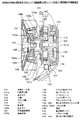
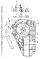
図1は本実施形態に係るエンジン始動装置とエンジンのクランク軸との組み付け構造を示す縦断面配置図、図2は前記エンジンをエンジン始動装置側から見た背面図である。
Hereinafter, a preferred embodiment of an engine starter according to the present invention will be specifically described with reference to the drawings. In the present embodiment, a power transmission mechanism between a starter of a small air-cooled internal combustion engine applied to a chainsaw and the engine is illustrated, but a brush cutter equipped with the same type of engine starter and engine, Of course, the present invention is applied to a rotary saw or the like.
FIG. 1 is a longitudinal sectional view showing an assembly structure of an engine starting device and an engine crankshaft according to this embodiment, and FIG. 2 is a rear view of the engine as viewed from the engine starting device side.
図1及び図2に示すとおり、図示を省略したエンジンのクランク軸105にはファン106が固設されており、そのファン106のエンジン始動装置側の背面には、後述する遠心クラッチ機構の一構成部材である杆状係脱部材107を回転自在に枢支する枢支部106aが、クランク軸105を挟んで一体に形成されている。この枢支部106aは、図2に示すようにクランク軸105を挟んで180°の位相差をもって一対配されており、その形状はエンジン始動装置側から見て扇型をなしている。これらの枢支部106aに前記杆状係脱部材107が回転自在に枢着されている。同杆状係脱部材107は、図1に示すとおり、側面から見ると杆状係脱部本体107aの一端に直角に屈曲された係脱爪部107bが立ち上がる形状をもち、平面から見ると中央部に前記枢支部106aにねじ込まれる止めネジ106bを挿通するネジ挿通孔が形成され、そのネジ挿通孔から前記係脱爪部107bとは反対側に所要の角度をもって延在する先端を細く形成された尾部107cを有している。杆状係脱部材107とファン106との間に図示せぬ捩じりバネが介在され、同捩じりバネの弾力によって前記係脱爪部107bを常にクランク軸側へと押し付けるように付勢している。
As shown in FIGS. 1 and 2, a
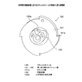
前記杆状係脱部本体107aの平面形状は、本発明の最も重要な部分を構成する。図3は、前記杆状係脱部材107の代表的な全体形状の一例を拡大して示している。同図に示すように、杆状係脱部本体107aと尾部107cとの枢着部107dには、上述のとおりネジ挿通孔が形成されたリング状をなしている。前記杆状係脱部本体107aの一側面は弓状に湾曲して内側に凹んだ凹陥面107eに形成されている。杆状係脱部材107を上記ファン106の枢支部106aに止めネジ106bを介して枢着するときは、図2に示すように、前記凹陥面107eをクランク軸105に向けるようにして取付ける。こうしてファン106に取り付けられた一対の杆状係脱部材107の係脱爪部107bは、エンジン始動装置100の後述する回転従動部Mの第2ラチェット部122に係合する。
The planar shape of the hook-shaped engaging / disengaging portion
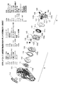
図4はエンジン始動装置100の半部ケース体101と同ケース体101の内部に配される作動部材の分解斜視図である。図1及び図4を参照しながら、本実施形態におけるエンジン始動装置の具体例を説明する。
FIG. 4 is an exploded perspective view of the
本実施形態におけるエンジン始動装置100は、その主軸103に回転可能に取着された回転従動部Mの回転中心とエンジン側のクランクシャフト11の軸中心とが向かい合うようにして組付けられる。エンジン始動装置100の構成部材は、図4に示すように、全て反エンジン側の半部ケース体101に収容されている。前記半部ケース体101には、同図に示すとおり、円筒ボス部101aがクランク軸側に向けて突設されている。この円筒ボス部101aには主軸103の基部が固着されており、以下に述べる各エンジン始動装置100の構成部材が前記主軸103に順次組付けられて止めネジ102によって固定される。
The engine starter 100 according to this embodiment is assembled such that the rotation center of the rotation follower M that is rotatably attached to the
前記エンジン始動装置100は回転駆動部Dと回転従動部Mとを備えている。前記回転駆動部Dは、前記半部ケース体101の内面に外側フック端110aを当接固定するリコイル用ゼンマイ110と、中央部に前記円筒ボス部101aに外嵌される円形孔112が形成され、同リコイル用ゼンマイ110を収容して、同ゼンマイ110の前記外側フック端110aとともに半部ケース体101の内面に当接され位置決め固定するゼンマイケース113と、一端にグリップ114を有するリコイルロープ115と、同リコイルロープ115の他端を巻回し周面上の一部に固定して前記リコイルロープ115を巻き回すリコイル用リール116とを備えている。
The engine starter 100 includes a rotation driving unit D and a rotation driven unit M. The rotational drive part D is formed with a
一方の回転従動部Mは、図1及び図4に示すように、径の異なる第1及び第2のラチェット部121,122が同軸線上に一体化して配されたラチェットホイール120を備えている。このラチェットホイール120の回転駆動部D側の背面中央部には、図5及び図6に示すとおり、ラチェットホイール120の回転中心Oから偏位した位置を中心O’とする円形突部123が突設されており、同円形突部123の周縁部の一部には前記中心O’に向かうU字状の切欠き溝123aが形成されている。大径の前記第1ラチェット部121のラチェット歯121aには、図7〜図10に示すように、本発明の後述する第1係脱杆141が係脱し、小径の第2ラチェット部122のラチェット歯122aには、図7に示すように上記クランクシャフト105に取り付けられた遠心クラッチ機構の構成部材である上記係脱爪部107bが係脱する。図示例によれば、前記第1ラチェット部121及び第2ラチェット部122は4つのラチェット歯121a,122aを有しており、両ラチェット部121,122は同一方向の回転のみを許容するために、回転が許容される方向とは反対側に係着面を有している。小径の第2ラチェット部122は、図1に示すように前記係脱爪部107bと係合しているため、エンジンを始動するまでは、本発明における緩衝・蓄力手段の一部である香箱130の蓄力方向の回転に追随して回転することなく停止した状態におかれる。
As shown in FIGS. 1 and 4, one rotation follower M includes a
前記回転駆動部Dと回転従動部Mとの間には、図1、図4及び図9に示すように、本実施形態における緩衝・蓄力手段であるゼンマイ香箱130と同香箱130に収納された蓄力用ゼンマイ131とが介装されている。本実施形態によれば、図9に一部破断して拡大して示すように、前記香箱130のゼンマイ収容部130aの内周面には、前記蓄力用ゼンマイ131の外側フック部131aと係合して、蓄力用ゼンマイ131を蓄力方向に巻き込むための複数個の突部130bが等間隔で突出している。この突部130bの形状は、前記リコイル用リール116の蓄力方向に回転したとき、蓄力用ゼンマイ131の上記外側フック部131aが係合するための係合面130b−1が形成され、その頂点部130b−2から反蓄力方向に向けて収容部130aの内周面に向けてなだらかに下傾斜する傾斜面130b−3が形成されている。一方、前記蓄力用ゼンマイ131の内側フック部131bは上記回転従動部Mのラチェットホイール120の上記円形突部123に形成されたU字状の上記切欠き溝123aに嵌着固定されている。前記香箱130の従動部側の開放面は環状カバー133により閉塞され、内部に収容された蓄力用ゼンマイ131の軸線方向の動きを規制している。
As shown in FIGS. 1, 4, and 9, between the rotation driving unit D and the rotation driven unit M, the
前記突部130bは、トルクリミット機構の一部を構成しており、蓄力用ゼンマイ131の蓄力がエンジンを始動させるに十分な量に達すると、それ以上は外側フック部131aとの係合を維持できなくなり、外側フック部131aとの係合が外れて同外側フック部131aが前記突部130bを次々と越えていき、蓄力用ゼンマイ131にもそれ以上の蓄力ができなくなる。この外側フック部131aが前記突部130bを越えるときに発する音により、蓄力用ゼンマイ131の蓄力が限界に達したことを外部に知らしめる。なお、本実施形態にあっては、トルクリミット機構を香箱130と蓄力用ゼンマイ131との間で構成しているが、例えば回転従動部Mにトルクリミット機構を設けることもできる。
The
前記香箱130の外周面には、図12、図13に示すように内部に収納された蓄力用ゼンマイ131の蓄力方向(図12の時計方向)の回転は許容するが、その逆の回転を阻止する一方向回転機構としての複数の外周ラチェット歯130cが交互にピッチ差をもたせて一体に形成されている。この一方向回転機構としてはラチェット機構が一般的であるが、他にも多様な形式の一方向回転機構を採用することもでき、その設置部位も必ずしも香箱130の外周面に限らない。前記外周ラチェット歯130cに上記第2係脱杆142が係脱する。一方、香箱130のリコイル用リール116と対面する背面中央部には、図13に示すように小ラチェット部132が形成されており、前記リコイル用リール116の前記小ラチェット部132との対面部には、図4に示すように、前記香箱130を蓄力方向にのみ回転させるため、同小ラチェット部132のラチェット歯132aと弾性的に係脱する係脱爪杆116aが設けられている。上記外周ラチェット歯130cの上記第2係脱杆142との係合面は、蓄力用ゼンマイ131の蓄力方向に向けられており、香箱130の背面側に設けられた前記小ラチェット部132のラチェット歯132aの前記係脱爪杆116aとの係合面は、上記回転従動部Mのラチェットホイール120の第1ラチェット部121のラチェット歯121aの係合面とは反対方向に向けられている。
As shown in FIGS. 12 and 13 , the outer circumferential surface of the
図示例によれば、前記小ラチェット部132のラチェット歯132aは90°の位相差をもって香箱130に一体に形成されており、対する前記係脱爪杆116aは前記リコイル用リール116の香箱側の周縁部に180°の位相差をもって2個がリコイル用リール116の回転中心に関して点対称に配され、その一端をリコイル用リール116の周縁部に枢着している。この係脱爪杆116aは、図示せぬ捩じりバネ116bによって常に前記ラチェット歯132aと係合する方向に付勢されている。一対の係脱爪杆116aは4個の前記ラチェット歯132aのうち、180°の位相差をもって配される2個のラチェット歯132aと同時に係合して、リコイル用リール116と香箱130とは蓄力方向に回転するが、反蓄力方向にはリコイル用リール116だけが回転可能とされる。
According to the illustrated example, the
ここで、本実施形態にあっては、上記リコイル用リール116の2個の係脱爪杆116aが上記香箱130の小ラチェット部132の2つのラチェット歯132aと係合した状態にあるとき、リコイルロープ115を引いてリコイル用リール116を蓄力方向(図12の時計方向)に回転させて、香箱130を同じく蓄力方向に回転させることにより、上記第1係脱杆141が係合して停止状態にある上記ラチェットホイール120との間で、蓄力用ゼンマイ131に十分な蓄力がなされる。ここで、第1係脱杆141をラチェットホイール120から外すと図示せぬエンジンが瞬時に始動する。
Here, in this embodiment, when the two engagement /
図1、図4及び図7において、符号141は上記ラチェットホイール120の大径の第1ラチェット部121と係脱する上記第1係脱杆を示し、符号142は前記香箱130の外周面に形成された外周ラチェット歯130cと係脱する上記第2係脱杆を示し、符号143は前記第1係脱杆141の係脱を行うための操作手段であるスライドスイッチを示している。ここで、第1係脱杆141及び後述するリンク片143cは金属製であり、第2係脱杆142はゼンマイ香箱130がプラスチック製であるため同じくプラスチックを使っている。
1, 4, and 7,
前記第1及び第2係脱杆141,142はそれぞれがく字状を呈しており、図4及び図7に示すように、その屈曲部が半部ケース体101の上壁面に近い位置に並んで回動自在に枢着されている。第1係脱杆部141は上記ラチェットホイール120の大径の第1ラチェット部121と係脱する係着爪杆部141aと同係着爪杆部141aを屈曲部を中心に回動操作する操作部141bとからなり、係着爪杆部141aは捩じりバネ144によって大径の第1ラチェット部121と係合する方向に付勢されている。一方の上記第2係脱杆142は、上記ゼンマイ香箱130の外周面に形成された外周ラチェット歯130cに係脱する係着爪杆部142aと同係着爪杆部142aを屈曲部を中心に回動操作する操作部142bとからなり、前記係着爪杆部142aは捩じりバネ145によって香箱130の前記外周ラチェット歯130cと係合する方向に付勢されている。
Each of the first and second engagement /
また本実施形態にあっては、半部ケース体101の上面端部に上記スライドスイッチ143が図7の左右方向にスライド可能に取り付けられている。このスライドスイッチ143の構造は、図4、図7及び図10に示すように、上部が上方に湾曲して膨出する上面に多数の凹凸面が形成された操作片143aと、その下面から下方に突設して半部ケース体101に形成された図示せぬスリットに嵌挿されたスライド片143bとを有している。このスライド片143bと前記第1係脱杆141の操作部141bの先端部とがリンク片143cにより連結されている。リンク片143cの一端は第1係脱杆141の操作部141bの先端部に相対回転可能に取り付けられ、リンク片143cの他端は前記スライド片143bに形成されている図示せぬスリットに摺動可能に取り付けられている。
In the present embodiment, the
そして前記第1及び第2係脱杆141,142は、リンク片143cを介して前記第1係脱杆141が上記ラチェットホイール120の大径ラチェット部121から離脱している状態では、図10に示すように同第1係脱杆141の操作部141bの先端部が前記第2係脱杆142の操作部142bの先端部を上方から押し下げ、第2係脱杆142の係着爪杆部142aが香箱130の前記外周ラチェット歯130cから離脱するように配置されている。また反対に、スライドスイッチ143を半部ケース体101の上部右寄りから図7に示す左方へとスライドさせることにより、前記第1及び第2係脱杆141,142は、互いがリンク片143cとの拘束を断たれて、各捩じりバネ144,145の弾力によって、ラチェットホイール120の第1ラチェット部121と香箱130の前記外周ラチェット歯130cと、それぞれに係着する方向に回動する。
The first and second engaging / disengaging
いま、半部ケース体101上の右寄りにある前記スライドスイッチ143を、図7に示す左側へとスライドさせると、第1及び第2係脱杆141,142は捩じりバネ144,145の弾力を受けて、ゼンマイ香箱130の外周ラチェット歯130c及びラチェットホイール120の大径ラチェット部121と係合する。この状態で、リコイルロープ115を引いてリコイル用リール116を回転させると、ゼンマイ香箱130は蓄力方向に回転するが、第2係脱杆142と外周ラチェット歯130cとが係合しているため反対方向の回転は止められている。このとき回転従動部Mのラチェットホイール120は、蓄力用ゼンマイ131のバネ力を解放する方向の力を受けているが、第1係脱杆141が係合しているため、一切回転が止められている。そのため、リコイルロープ115を引いてリコイル用リール116を回転させると、香箱130が回転してラチェトホイール120との間で、蓄力用ゼンマイ131の蓄力だけがなされる。
Now, when the
ここで、リコイルロープ115の引き操作を途中で止めてリコイルロープ115から手を離しても、そのまま蓄力は香箱130とラチェットホイール120との間に保持されることになる。従って、例えば力の弱い人による引き操作や、リコイルロープ115の引き操作が自由に行えないような場所では、何回かに分けてリコイルロープ115を引いて、蓄力用ゼンマイ131にエンジンを始動させるに十分なバネ力を貯えたのちに、第1及び第2係脱杆141,142の係合を解除して第1始動モードに切り替えれば、瞬時にエンジンを始動させることができる。このとき貯えられた蓄力がエンジンを始動させるに十分な力に達したかどうかは、既述したトルクリミット機構の作動により発せられる報知信号により確実に知ることができる。
Here, even if the pulling operation of the
こうしてゼンマイ131に十分な蓄力がなされたのちに、上記スライドスイッチ143を図10に示す右側へとスライドさせると、第1及び第2係脱杆141,142がゼンマイ香箱130の外周ラチェット歯130cとラチェットホイール120の第1ラチェット部121との係合が外れ、瞬時にエンジンを始動させる。エンジンの回転速度が所定の速度を越えると、エンジン側のファン106に取り付けられた遠心クラッチ機構の上記杆状係脱部材107が遠心力を受けて、図11に示すように、その係脱爪部107bと前記ラチェットホイール120の第2ラチェット部122との係合が外れ、前記ラチェットホイール120の回転は自動的に停止し、エンジンは回転を続ける。
After the
ところで、かかる構成を備えたエンジンを搭載する手作業機は、作業が終了すれば早々に点火スイッチを切ってエンジンの駆動を停止させる。このエンジン停止のとき、クランク軸105の停止位置は一定ではなく360°の範囲で変動し、ファン106に取り付けられた遠心クラッチ機構の2個一対の杆状係脱部材107も当然にその停止位置が変動する。一方、回転が停止している上記第2ラチェット部122のラチェット歯122aの停止位置は常に定位置にある。そのため、エンジンの停止時に、その停止位置が変動する遠心クラッチ機構の前記杆状係脱部材107bは、例えば図7〜図10に示すように様々な位置で停止することになる。
By the way, a manual work machine equipped with an engine having such a configuration turns off the ignition switch as soon as the work is completed to stop the driving of the engine. When the engine is stopped, the stop position of the
図14〜図16は、エンジンの停止時における上記クランク軸105に取り付けられた遠心クラッチ機構に採用される通常の形状をもつ杆状係脱部材117の3種類の停止位置の例を示している。図14に示すように、前記杆状係脱部材117の係脱爪部117bが上記第2ラチェット部122のラチェット歯122aに当接した状態で停止している場合には格別の問題は生じない。一方、この杆状係脱部材117の杆状係脱部本体117aの形状は、これらの図に示すように、単純な短冊状の板片に過ぎない。いま、仮に図15に示す位置で杆状係脱部材117が停止しているとき、上述のようにリコイルロープを引いてゼンマイ香箱130に収容されたゼンマイに蓄力したのち、スライドスイッチ143を同図の左側にスライドさせて、第1及び第2の係脱杆141,142をラチェットホイール120の第1ラチェット121とゼンマイ香箱130の外周ラチェット歯130cとの各係合を外すと、ラチェットホイール120は図16に矢印で示す方向に急速に回転する。
FIGS. 14 to 16 show examples of three types of stop positions of the hook-shaped engagement /
このとき、上記杆状係脱部材117の係脱爪部117bは第2ラチェット部122のラチェット歯122aの頂点位置に乗り上げた状態で停止しているため、前記ラチェットホイール120の時計方向の回転により杆状係脱部材本体117aの内側側面が押し上げられて、同杆状係脱部材117をその中央枢着部を中心に時計方向に回動させて係脱爪部117bが前記ラチェット歯122aから遠ざかる方へと立ち上がる。このときの係脱爪部117bの前記ラチェット歯に対する係合面は、次位のラチェット歯の係合面と対面せず、他所の方向を向いている。この状態で前記第2ラチェット部122は急速に回転しており、次位の前記ラチェット歯が急速に接近し、前位にある前記ラチェット歯が杆状係脱部材117の中央枢着部117に対応する内側側面を過ぎたとき、前記杆状係脱部材117の係脱爪部117bは図示せぬ捩じりバネの付勢により、次位の前記ラチェット歯の係合面に向かってお辞儀をするように挙動する。しかし、前記係脱爪部117bの前記挙動がラチェット歯の回転に間に合わず、係脱爪部117bの係合面が完全にはラチェット歯の係合面と対峙しない状態で、ラチェット歯の刃先部分が係脱爪部117bの爪先部分と激しく衝突する。その結果、その衝突時の衝撃力で双方の衝突部分が破壊してしまう。
At this time, the engagement / disengagement claw portion 117b of the hook-shaped engagement /
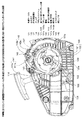
本実施形態によると、こうした不具合が解消される。本実施形態による杆状係脱部材107も、図7〜図9に示すように、エンジンの停止時に停止する位置は様々である。図7は、杆状係脱部材107の係脱爪部107bの係合面が第2ラチェット部122のラチェット歯122aの係合面と対峙して、杆状係脱部材107が停止したときの状態を示している。この図7に示すように、係脱爪部107bの係合面とラチェット歯122aの係合面とが対峙して停止する場合には、第1係脱杆141を操作して第1ラチェット部121との係合を外して、図10に示すようにラチェットホイール120を蓄力解放方向へ急激に回転させても、係脱爪部107bの係合面とラチェット歯122aの係合面とが即座に当接しあって係合するため、当然に格別の問題は生じない。
According to the present embodiment, such a problem is solved. As shown in FIGS. 7 to 9, the hook-like engagement /
一方、例えば図8や図9に示すように、仮に係脱爪部107bがラチェット歯122aの頂部に乗り上げた状態で停止したり、或いは係脱爪部107bがラチェット歯122aを乗り越えた状態で停止しても、杆状係脱部材本体107aのラチェットホイール120側の側面形状が、その中央係着部から前記係脱爪部107bにかけて、ラチェットホイール120から離れる方向に湾曲して凹んだ凹陥面に形成されているため、第2ラチェット部122の回転により係脱爪部107bが前位のラチェット歯122aを乗り越えたときには、図9に示した状態と同様に、係脱爪部107bの係合面が次位のラチェット歯122a’の係合面と対峙しており、係脱爪部107bと次位のラチェット歯122aとが確実に面係合する。その結果、本実施形態によるエンジン始動装置100とエンジンとの同力伝達機構である杆状係脱部材107の係脱爪部107bとラチェットホイール120の第2ラチェット部122との係脱動作が円滑になされるようになり、係脱爪部107bとラチェット歯122aとの間で破壊を起こすことがなくなる。
On the other hand, as shown in FIGS. 8 and 9, for example, the engagement /
自動断接手段と第2ラチェット歯との面係合を確実なものとするために、前記第1ラチェットと第2ラチェットの歯は互い違いの位相差を有して配されており、位相差を持つことで、蓄力時に回転駆動部を回動した際の、第1ラチェット部と前記係脱杆との係合までの回転従動部の若干の回動が、前記エンジン側自動断接手段の係脱爪部と第2ラチェット歯との係合がしっかり面係合した状態にする確立を高め、且つ仮に面係合していない状態であったとしても、前記係脱杆部と第2ラチェット歯との距離が短い状態で蓄力を維持しているので、蓄力開放時にしっかり面係合され、蓄力による駆動力をエンジンにより確実伝えることが出来る。 In order to ensure the surface engagement between the automatic connecting / disconnecting means and the second ratchet teeth, the teeth of the first ratchet and the second ratchet are arranged with staggered phase differences. Thus, when the rotation drive unit is rotated during power storage, the rotation of the rotation follower until the engagement of the first ratchet unit and the engagement / disengagement rod is caused by the engine side automatic connection / disconnection means. Even if the engagement between the engagement / disengagement claw portion and the second ratchet teeth is in a state where the engagement is firmly surface-engaged and the surface engagement is not achieved, the engagement / disengagement portion and the second ratchet Since the accumulated force is maintained in a state where the distance to the teeth is short, the surface is firmly engaged when the accumulated force is released, and the driving force due to the accumulated force can be reliably transmitted by the engine.
ところで、以上の説明は第1係脱杆141を回転従動部Mのラチェットホイール120の第1ラチェット部121に係合させて蓄力解放方向の回転を禁止し状態で、リコイルロープ115を引いてリコイル用リール116を介してゼンマイ香箱130を一方向に回転させてゼンマイ131に蓄力し、その蓄力がエンジンを始動させるに十分な蓄力となったとき、前記第1係脱杆141を操作して第1ラチェット部121との係合を解除し、遠心クラッチ機構である第2ラチェット部122と杆状係脱部材107との係合を維持しながらエンジンを始動させる場合について説明した。
By the way, in the above description, the first engagement /
しかるに、熟練作業者にとっては前述のようなゼンマイ131の蓄力操作を予め行ってからエンジンを始動させるのは、作業の効率化を妨げるとして敬遠する場合が多い。本実施形態では、スライドスイッチ143を、図10に示すように半部ケース体101上を左から右へとスライドさせると、第1及び第2係脱杆141,142がラチェットホイール120及びゼンマイ香箱130からそれぞれ離脱する。ここで、リコイルロープ115を引いてリコイル用リール116を回転させることにより香箱130を回転させる。蓄力ゼンマイ131にエンジンの最大負荷を越えるに十分な蓄力がなされる前は、エンジンのクランク軸105にファン106を介して取付けられた上記遠心クラッチ機構の杆状係脱部材107との係合によりラチェットホイール120の回転は停止している。蓄力用ゼンマイ131に、エンジンの最大負荷を越える十分なバネ力が蓄えられると、自動的にラチェットホイール120を蓄力の解放方向に回転させ、前記遠心クラッチ機構を介してエンジンのクランクシャフト105が回転してエンジンを始動させる。
However, for skilled workers, it is often avoided to start the engine after the power storage operation of the
この蓄力時の途中で、前記リコイルロープ115の引き操作を途中で止めると、上記ラチェットホイール120及び香箱130が第1及び第2係脱杆141,142と係合していないため、ラチェットホイール120及び香箱130は逆転を始め、それまで蓄力されていた蓄力用ゼンマイ131のバネ力が自動的に解放される。その結果、リコイルロープ115の引き操作を途中で止めて手を離しても、緩衝・蓄力手段の蓄力が自然と解放され、不用意にエンジンが始動してしまうような恐れはない。
If the pulling operation of the
また本実施形態にあっては、上記ラチェットホイール120の耐久性を向上させるため、その第1ラチェット部121のラチェット歯121aの形状にも改良がなされている。通常、この種のラチェットホイールのラチェット歯はホイール本体から径方向の外側に立ち上がる係合面を有する平たい直角三角形状に作られている。かかる形状のラチェット歯であると、たとえラチェットホイール及び同ラチェットホイールと係脱するラチェット爪部とを金属製で作っても、第1係脱杆141との係脱の回数が増えるとラチェット歯121aの係脱面及びラチェット爪部の係脱面に摩耗が生じ、僅かな衝撃を受けても係合が外れてしまうようになる。また、前記ラチェット歯121aの係脱面の立ち上がり基端部とラチェットホイール120の本体との間に形成される隅角部に第2係脱杆142の爪部が強く当たると、そこにラチェットホイール120の中心側に向かうクラックが発生することがある。これらの課題を解消しようとして、従来は前記ラチェット歯121a及びラチェット爪部の、特に係脱面に窒化加工などの表面処理を施して、表面硬度を高めて摩耗を避けるようにしていた。しかしながら、上記課題は一向に解消されていない。
In this embodiment, in order to improve the durability of the
そこで本実施形態にあっては、図5及び図6に示すように、上記第1ラチェット部121のラチェット歯121aの係脱面を径方向から係脱側へと所定の傾斜角αをもって外側に向けて傾斜させて立ち上げており、同時に前記ラチェット歯121aの立ち上がり基端部とホイール本体との間に形成される隅角部にホイール中心側に向けて所要の長さの切欠き部121bを形成している。ラチェット歯121aの係脱面を径方向から係脱側に向けて所定の傾斜角αをもって傾斜させて立ち上げているため、その歯先部分が摩耗しても、係脱面の基部側が傾斜角αにより、係合時に相手方の爪部が確実に把持係止して簡単には離脱しなくなる。また、前記ラチェット歯121aの立ち上がり基端部とホイール本体との間に形成される隅角部に切欠き部121bを形成しているため、同隅角部に作用する衝撃力が切欠き部121bを介して分散し、クラック等の発生がなくなり、更に耐久性が増す。
Therefore, in the present embodiment, as shown in FIGS. 5 and 6, the engagement / disengagement surface of the
また、第1係脱杆141を板金からプレス加工により製作する場合は、図20に示すように、その係着爪杆部141aの先端部を直角に折り曲げて係着爪141a’を形成する場合には、その係着爪141a’の折曲げ長さにより相手方の第1ラチェット部121のラチェット歯121aとの係合部のクランク軸線方向の掛かり幅を大きく取ることができ、第1ラチェット部121と前記係着爪141a’との係合部において、クランク軸線方向の動きがある程度許容できるようになるため、僅かな外力による係合が解除されることを防止することができる。第1係脱杆141と第1ラチェット部121との材質が金属製であるとき、同第1係脱杆141の材質を第1ラチェット部121の材質に比べて硬度を低くしておけば、繰返しの使用では同係脱杆側が磨耗するようになっており、その磨耗も第1ラチェットとの係合がクランク軸線方向の動きを規制する形状へと磨耗するので、係合が更に強固なものとなる。
Further, when the first engagement /
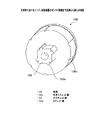
図17及び図18は、上記ラチェットホイール120の背面側に形成された上記円形突部123のU字状の切欠き溝123aの変形例を示している。この変形例によれば、前記切欠き溝123aの一方の肩部を更に切り欠いて略逆J字状の切欠き溝123bとしている。この切欠き溝123bにも、前記U字状の切欠き溝123aと同様に、図7に示すエンジン側から見て時計方向に巻き回されている蓄力用ゼンマイ131の内側フック部131bが嵌着固定される。この切欠き溝の形状が上述のごとくU字状である場合には、上述のように第2係脱杆142がラチェットホイール120から離脱して蓄力用ゼンマイ131の蓄力を開放する瞬間に、同切欠き溝123aに嵌着された蓄力用ゼンマイ131の内側フック部131bからU字状切欠き溝123aの一方の肩部を跨いで延びる部分が、同片部を激しく叩き、蓄力用ゼンマイの内端フック部を損傷させてしまう。その対処法を探ったところ、元来、前記一方の肩部は不要であることが判明した。そのため、前記一方の肩部を切り欠いたところ、前記蓄力用ゼンマイ131の内端フック部131bの耐久性が向上した。
17 and 18 show a modification of the
以上の実施形態では、回転従動部Mのラチェットホイール120の第1ラチェット部121とゼンマイ香箱130の外周ラチェット歯130cに、それぞれ第1及び第2係脱杆141,142が連動して係脱させるようにしている。しかしながら、本発明では前記ゼンマイ香箱130の外周ラチェト歯130aと同外周ラチェット歯130cと係脱する第2係脱杆142を排除することもできる。この場合には、ゼンマイ香箱130を軸受型のワンウェイクラッチを介して主軸103に取り付ける。
In the above embodiment, the first and second engagement /
図19は、本発明における第2の実施形態を示している。同図から理解できるように、この実施形態ではゼンマイ香箱130の外周にラチェット歯が形成されておらず、単なる平滑な周面を有しているに過ぎない。また、図4と比較すると分かるように、第2係脱杆142も存在しない。その他の構造は、上記実施形態と実質的に変わるところがない。従って、回転従動部Mのラチェットホイール120の大径の第1ラチェット部121と係脱する第1係脱杆141と、前記ラチェットホイール120の小径の第2ラチェット部122と係脱するクランク軸105に取り付けられた上記杆状係脱部材107とは、図7に示す態様と実質的に同一である。前記杆状係脱部材107の形状も、図3に示してような本発明に特有の上記形状を有している。
FIG. 19 shows a second embodiment of the present invention. As can be understood from the figure, in this embodiment, ratchet teeth are not formed on the outer periphery of the
回転従動部Mは、前述のとおり上記第1番目の実施形態と同様に、大径と小径の第1及び第2ラチェット部121,122を有するラチェットホイール120を備えている。このラチェットホイール120の背面には、既述したとおり上記蓄力用ゼンマイ131の内側フック部131bが小径円形突部123に形成された上記U字状の切欠き溝123aに嵌着固定されており、その大径の第1ラチェット部121には前記第1係脱杆141が係合しているため、同係合を解除するまでラチェットホイール120は停止状態にある。このとき、図示せぬエンジンのファン10を介してクランク軸105(図1参照)に取り付けられた杆状係脱部材107(図3参照)は、図7〜図9に示したとおり小径の第2ラチェット部122のラチェット歯122aに対して不定な位置で停止している。この状態で、上記第1実施形態と同様に、スライドスイッチ143を操作して第1係脱杆141と上記ラチェットホイール120の大径の第1ラチェット部121との係合を外す。
As described above, the rotation driven portion M includes the
ここで、リコイルロープ115を引いてリコイル用リール116を回転させることによりゼンマイ香箱130を蓄力方向に回転させ、蓄力用ゼンマイ131に十分なバネ力を貯えさせて、その蓄力がエンジンを始動させるに十分な力に達したとき、回転従動部Mのラチェットホイール120を介して図示せぬ上記遠心クラッチ機構を介してエンジンのクランクシャフト105に回転力を伝達し、自動的にエンジンを始動させる。
Here, by pulling the
反対に、半部ケース体101上の右寄りにある前記スライドスイッチ143を左側へとスライドさせると、上記第1係脱杆141は捩じりバネ144の弾力を受けて、ラチェットホイール120の第1ラチェット部121と係合する。この状態で、リコイルロープ6を引いてリコイル用リール116を回転させると、ゼンマイ香箱130を蓄力方向に回転させることができるが、図示せぬワンウェイクラッチにより反対方向の回転が阻止され、同時に回転従動部Mのラチェットホイール120は一切回転を止められる。そのため、リコイルロープ115を引いてリコイル用リール115を回転させると、ゼンマイ香箱130が回転して蓄力用ゼンマイ131に蓄力だけが貯えられるようになる。
On the other hand, when the
そのため、リコイルロープ115の引き操作を途中で止めて手を離しても、そのまま蓄力はゼンマイ香箱130とラチェットホイール120との間で蓄力用ゼンマイ131に保持されることになる。従って、例えば力の弱い人による引き操作や、リコイルロープ115の引き操作が自由に行えないような場所では、何回かに分けてリコイルロープ115を引いて、蓄力用ゼンマイ131にエンジンを始動させるに十分なバネ力を貯えたのちに、上記スライドスイッチ143を、図7に示すようにの右側へとスライドさせて、上記第1係脱杆141を時計方向に回動させて第1ラチェット部121から外すと、エンジンを瞬時に始動させる。この始動時に、上述のとおり第2ラチェット部122と係合するエンジン側の上記杆状係脱部材107の係脱爪部107bがいかなる位置にあろうとも、同杆状係脱部本体107の形状が、本発明の特殊形状をもつため、常に正確に第2ラチェット部122と面係合し、ラチェット歯122aの先端及び係脱爪部107bの先端が破壊することが回避される。また、前述のように蓄力用ゼンマイ131に貯えられた蓄力がエンジンを始動させるに十分な量に達したかどうかは、既述したトルクリミッタ手段の作動により発せられる報知信号により確実に知ることができる。
For this reason, even if the pulling operation of the
このように、本実施形態にあっては上記スライドスイッチ143を半部ケース体101の表面上でスライドさせることにより、回転駆動部Dのリコイルロープ115の引き操作でリコイル用リール116をエンジン回転方向に回転させて、緩衝・蓄力手段のゼンマイ香箱130を同方向に回転させながら蓄力用ゼンマイ131に所要のバネ力を蓄えさせ、その蓄えられた蓄力を直接従動部Mであるラチェットホイール120に伝え、その蓄力がエンジンの始動に必要十分な力に達すると自動的にエンジンを始動させることができるばかりでなく、前記スライドスイッチ143を逆方向にスライドさせれば、前記回転駆動部Dのリコイルロープ115を引きゼンマイ香箱130を同方向に回転させて蓄力用ゼンマイ131にエンジン始動に必要なバネ力を予め蓄えさせておくことができ、その蓄えられた蓄力を保持した状態で、所望時に任意の場所で蓄力用ゼンマイ131に貯えられた前記蓄力を開放し、その場で瞬時にエンジンを始動させることができる。
As described above, in this embodiment, the
しかも、前記スライドスイッチ143の操作で任意の時期にエンジンを始動させる場合に、本発明の動力伝達機構である遠心クラッチ機構のラチェットホイール120の第2ラチェット部122とエンジン側の杆状係脱部材107の係脱爪部107bとの係合が円滑になされるようになり、従来のように前記ラチェット歯122aの歯先部と前記係脱爪部107aの爪先部との破壊が、前記杆状係脱部材107の形状を特有の形状としたことにより確実に回避されるようになる。
In addition, when the engine is started at an arbitrary time by the operation of the
なお上記実施形態では、いずれも管状係脱部材107の材質を金属材料としているが、その形状を変更するとともに、硬度と強度が確保されれば管状係脱部材107をプラスチック材料により成形することも可能である。
In the above embodiment, the material of the tubular engagement /
100 エンジン始動装置
101 半部ケース体
101a 円筒ボス部
102 止めネジ
103 主軸
105 クランク軸
106 ファン
106a 枢支部
106b 止めネジ
107 杆状係脱部材
107a 杆状係脱部本体
107b 係脱爪部
107c 舌片部
107d 連結部
107e 凹陥面
110 リコイル用ゼンマイ
110a 外側フック端
112 円形孔
113 ゼンマイケース
114 グリップ
115 リコイルロープ
116 リコイル用リール
116a 係脱爪部
116b 捩じりバネ
120 ラチェットホイール
121,122 第1及び第2のラチェット部
121a,122a ラチェット歯
123 円形突部
123a (U字状の)切欠き溝
123b (逆J字状の)切欠き溝
130 香箱
130a ゼンマイ収容部
130b 突部
130b−1 係合面
130b−2 頂点部
130b−3 傾斜面
130c 外周ラチェット歯
131 蓄力用ゼンマイ
131a 外側フック部
131b 内側フック部
132 小ラチェット部
132a ラチェット歯
133 環状カバー
141,142 第1及び第2係脱杆
141a,142a 係着爪杆部
141b,142b 操作部
143 スライドスイッチ
143a 操作片
143b スライド片
143c リンク片
144,145 捩じりバネ
D 回転駆動部
M 回転従動部
O,O’ 中心
α ラチェット歯の傾斜角
DESCRIPTION OF SYMBOLS 100
Claims (6)
前記緩衝・蓄力手段が、ゼンマイ香箱と同香箱に一端を支持されたゼンマイとを有し、前記回転従動部は前記ゼンマイの他端を支持するとともに、外部操作により係脱して回転従動部の一方向の回転をロック及び解除する第1係脱杆と、同係脱杆と係脱する複数のラチェット歯を有する第1のラチェット部と、前記自動断接手段と係脱する複数のラチェット歯を有する第2ラチェット部とを備え、
前記ゼンマイ香箱は、前記外部操作により前記第1係脱杆と協動して係脱しゼンマイ香箱の一方向の回転をロック及び解除する第2係脱杆と、外周面に同係脱杆と係脱する複数のラチェット歯を有する第3ラチェット部とを備え、
前記自動断接手段は、その枢着部がエンジンのファンやクランク軸などエンジン回転に連動する部材に枢支され、先端に係脱爪部を有するとともに、同係脱爪部が前記第2ラチェット部と係合する方向に付勢された杆状係脱部材を有し、エンジンのクランク軸が所要の回転速度に達したとき、前記杆状係脱部材が遠心力により前記付勢に抗して回動し、前記係脱爪部と前記第2ラチェット部のラチェット歯との係合が自動的に外れる遠心クラッチ機能を備えてなり、
前記杆状係脱部材の第2ラチェット部のラチェット歯と対面する側の側面が、その枢着部から前記係脱爪部にかけて前記第2ラチェット部の周面から離間する方向に凹んだ形状を有してなり、
前記第1係脱杆は板金のプレス加工により得られ、全体がく字形を呈し、その一端を90°に折り曲げた係着爪を形成してなる、
ことを特徴とするエンジン始動装置とエンジンとの間の動力伝達機構。 The power transmission system between the rotation drive unit and the rotation follower unit is provided with a buffer / accumulation means, and the power of the rotation follower unit is accumulated by the buffer / accumulation unit , and the rotation follower is driven when desired. Power of the engine starter and the engine which unlocks the part and releases the stored power and enables the engine to be started via the automatic connection / disconnection means arranged between the rotation follower and the engine A transmission mechanism,
The buffer / accumulation means has a mainspring barrel and a mainspring supported at one end by the same barrel, and the rotary follower supports the other end of the mainspring, and is disengaged by an external operation to disengage the rotary follower. A first engagement / disengagement mechanism for locking and releasing rotation in one direction, a first ratchet portion having a plurality of ratchet teeth for engagement / disengagement with the engagement / disengagement process, and a plurality of ratchet teeth for engagement / disengagement with the automatic connecting / disconnecting means. A second ratchet portion having
The mainspring barrel is engaged and disengaged in cooperation with the first engagement / disengagement by the external operation, and the second engagement / disengagement locks and releases the one-way rotation of the mainspring barrel. A third ratchet portion having a plurality of ratchet teeth to be removed,
The automatic connecting / disconnecting means is pivotally supported by a member interlocking with the engine rotation, such as an engine fan or a crankshaft, and has an engaging / disengaging claw portion at the tip, and the engaging / disengaging claw portion is the second ratchet. And a hook-like engaging / disengaging member biased in a direction to engage with the portion, and when the crankshaft of the engine reaches a required rotational speed, the hook-like engaging / disengaging member resists the biasing by a centrifugal force. And a centrifugal clutch function that automatically disengages the engagement / disengagement claw portion and the ratchet teeth of the second ratchet portion,
A side surface of the second ratchet portion of the hook-shaped engagement / disengagement member facing the ratchet teeth is recessed from the pivot portion to the engagement / disengagement claw portion in a direction away from the peripheral surface of the second ratchet portion. Ri name has,
The first engagement / disengagement is obtained by pressing a sheet metal, and the entire engagement is formed in a square shape, and an engagement claw with one end bent at 90 ° is formed.
A power transmission mechanism between the engine starter and the engine.
Priority Applications (7)
| Application Number | Priority Date | Filing Date | Title |
|---|---|---|---|
| JP2005031341A JP4376193B2 (en) | 2005-02-08 | 2005-02-08 | Power transmission mechanism between engine starter and engine |
| US11/883,664 US7819105B2 (en) | 2005-02-08 | 2006-02-02 | Power transmission mechanism between engine starting device and engine |
| ES06712930.4T ES2673504T3 (en) | 2005-02-08 | 2006-02-02 | Power transmission mechanism between an engine start and an engine |
| CN2006800041024A CN101128668B (en) | 2005-02-08 | 2006-02-02 | Power transmission mechanism between engine starter and engine |
| EP06712930.4A EP1865196B1 (en) | 2005-02-08 | 2006-02-02 | Power transmission mechanism between engine starter and engine |
| PCT/JP2006/301787 WO2006085473A1 (en) | 2005-02-08 | 2006-02-02 | Power transmission mechanism between engine starter and engine |
| SE0602011A SE529695C2 (en) | 2005-02-08 | 2006-09-27 | Power transmission mechanism between an engine starter and an engine |
Applications Claiming Priority (1)
| Application Number | Priority Date | Filing Date | Title |
|---|---|---|---|
| JP2005031341A JP4376193B2 (en) | 2005-02-08 | 2005-02-08 | Power transmission mechanism between engine starter and engine |
Publications (2)
| Publication Number | Publication Date |
|---|---|
| JP2006219993A JP2006219993A (en) | 2006-08-24 |
| JP4376193B2 true JP4376193B2 (en) | 2009-12-02 |
Family
ID=36793048
Family Applications (1)
| Application Number | Title | Priority Date | Filing Date |
|---|---|---|---|
| JP2005031341A Active JP4376193B2 (en) | 2005-02-08 | 2005-02-08 | Power transmission mechanism between engine starter and engine |
Country Status (7)
| Country | Link |
|---|---|
| US (1) | US7819105B2 (en) |
| EP (1) | EP1865196B1 (en) |
| JP (1) | JP4376193B2 (en) |
| CN (1) | CN101128668B (en) |
| ES (1) | ES2673504T3 (en) |
| SE (1) | SE529695C2 (en) |
| WO (1) | WO2006085473A1 (en) |
Families Citing this family (10)
| Publication number | Priority date | Publication date | Assignee | Title |
|---|---|---|---|---|
| JP2009293485A (en) * | 2008-06-04 | 2009-12-17 | Honda Motor Co Ltd | Power storage type recoil starter |
| US7886709B2 (en) * | 2009-05-29 | 2011-02-15 | GM Global Technology Operations LLC | Spring start for a vehicle engine |
| JP2013510974A (en) * | 2009-11-13 | 2013-03-28 | ディーティーアイ グループ ビー.ブイ. | Starting system for vehicle engine |
| JP5836713B2 (en) * | 2010-12-01 | 2015-12-24 | スターテング工業株式会社 | Recoil starter |
| DE202011000610U1 (en) * | 2011-03-17 | 2012-06-18 | Makita Corporation | Starting device for at least one internal combustion engine, in particular cable pull start device |
| TWI413729B (en) * | 2011-08-26 | 2013-11-01 | Sanyang Industry Co Ltd | Engine flameout restart signal generation mechanism |
| CN105736207A (en) * | 2016-03-18 | 2016-07-06 | 山东华盛农业药械有限责任公司 | Easy starting device |
| CN106090068B (en) * | 2016-08-17 | 2018-05-18 | 广东工业大学 | A kind of freewheel clutch |
| EP3744968A1 (en) | 2019-05-28 | 2020-12-02 | Andreas Stihl AG & Co. KG | Spring box and manually-operated turning gear comprising a spring box |
| CN113515816B (en) * | 2020-12-30 | 2023-07-21 | 中国航发沈阳发动机研究所 | Ratchet clutch disengagement rotating speed determining method |
Family Cites Families (43)
| Publication number | Priority date | Publication date | Assignee | Title |
|---|---|---|---|---|
| US3010443A (en) * | 1959-03-19 | 1961-11-28 | Garland E Lyvers | Engine starting device |
| JPS3825704Y1 (en) * | 1961-09-07 | 1963-11-28 | ||
| US3861374A (en) * | 1971-05-05 | 1975-01-21 | Mccullock Corp | Lightweight chain saw with engine restarting system and method and apparatus for restarting a warm internal combustion engine |
| US4104927A (en) * | 1976-11-29 | 1978-08-08 | Jensen Jorn Benned | Engine starter |
| FR2475663A1 (en) * | 1980-02-12 | 1981-08-14 | Renault | LOCKING DEVICE IN STOP POSITION FOR MOTOR VEHICLE |
| JPS5851271A (en) * | 1981-09-19 | 1983-03-25 | Mitsubishi Heavy Ind Ltd | Power accumulating type automatic starting apparatus for internal-combustion engine |
| US4480605A (en) * | 1983-05-09 | 1984-11-06 | Brunswick Corporation | Recoil starter |
| US4582030A (en) * | 1984-03-02 | 1986-04-15 | Tecumseh Products Company | Mounting recoil starter |
| JPS6491075A (en) | 1987-10-02 | 1989-04-10 | Hitachi Ltd | Magnetic field distribution measuring apparatus |
| JP2579650B2 (en) | 1987-11-27 | 1997-02-05 | オリンパス光学工業株式会社 | Internal laser light irradiation device |
| JPH0191075U (en) | 1987-12-08 | 1989-06-15 | ||
| JPH01190965A (en) * | 1988-01-22 | 1989-08-01 | Mitsubishi Heavy Ind Ltd | Spiral spring type starter device for internal combustion engine |
| JPH01191075A (en) | 1988-01-27 | 1989-08-01 | Nec Corp | Semiconductor aging device |
| JP2573340B2 (en) | 1988-11-24 | 1997-01-22 | 三菱重工業株式会社 | Spiral spring type starting device for general gasoline engine |
| US5083534A (en) * | 1989-04-05 | 1992-01-28 | Mitsubishi Jukogyo Kabushiki Kaisha | Spiral spring type starter apparatus for an internal combustion engine |
| US4970998A (en) * | 1989-05-26 | 1990-11-20 | Eaton Indiana, Inc. | Offset starter pawl |
| JPH05223025A (en) | 1992-02-10 | 1993-08-31 | Toyota Motor Corp | Device for controlling pressure in fuel tank |
| JPH07174061A (en) * | 1993-05-07 | 1995-07-11 | Nitsukari:Kk | Force storage type recoil starter |
| JP3496394B2 (en) * | 1996-05-08 | 2004-02-09 | トヨタ自動車株式会社 | Fluid torque converter |
| US6230678B1 (en) * | 1998-10-30 | 2001-05-15 | Briggs & Stratton Corporation | Starting and stopping device for internal combustion engine |
| US6615787B2 (en) * | 1998-10-30 | 2003-09-09 | Briggs & Stratton Corporation | Engine starting and stopping device |
| US6325036B1 (en) * | 1998-10-30 | 2001-12-04 | Briggs & Stratton Corporation | Starting and stopping device for an internal combustion engine |
| US6508220B1 (en) * | 1999-08-25 | 2003-01-21 | Kioritz Corporation | Starter |
| JP4017792B2 (en) | 1999-08-25 | 2007-12-05 | 株式会社共立 | Accumulated starter device |
| JP3274671B2 (en) | 1999-08-25 | 2002-04-15 | 株式会社共立 | Starter device |
| JP4581231B2 (en) | 2000-11-27 | 2010-11-17 | 富士電機システムズ株式会社 | Gate drive circuit for voltage driven semiconductor device |
| JP2002327666A (en) | 2001-03-01 | 2002-11-15 | Starting Ind Co Ltd | Starter device |
| DE60218923T2 (en) * | 2001-04-27 | 2007-12-06 | Maruyama Mfg. Co., Inc. | Starting devices for internal combustion engines |
| JP3820140B2 (en) * | 2001-04-27 | 2006-09-13 | 株式会社丸山製作所 | Internal combustion engine starter |
| JP4109838B2 (en) * | 2001-05-25 | 2008-07-02 | スターテング工業株式会社 | Recoil starter device |
| JP4069971B2 (en) | 2002-03-12 | 2008-04-02 | ハスクバーナ・ゼノア株式会社 | Engine recoil starter |
| US6959680B2 (en) * | 2002-07-24 | 2005-11-01 | Starting Industrial Co., Ltd. | Recoil starter |
| JP2004068639A (en) | 2002-08-02 | 2004-03-04 | Showa Kiki Kogyo Kk | Lock-type power accumulation starter |
| JP3680052B2 (en) | 2002-09-26 | 2005-08-10 | 株式会社クボタ | Engine recoil starter |
| CN100523481C (en) * | 2002-10-21 | 2009-08-05 | 开始工业株式会社 | Recoil startor |
| JP4346922B2 (en) | 2002-10-21 | 2009-10-21 | スターテング工業株式会社 | Recoil starter |
| JP3878564B2 (en) * | 2003-02-28 | 2007-02-07 | スターテング工業株式会社 | Accumulated recoil starter |
| US6901889B1 (en) * | 2004-03-10 | 2005-06-07 | Tgi, Inc. | Fumigation system for a diesel engine |
| JP2005337224A (en) * | 2004-04-28 | 2005-12-08 | Komatsu Zenoah Co | Engine starter |
| US7191752B2 (en) * | 2004-05-14 | 2007-03-20 | Husqvarna Outdoor Products Inc. | Energy storing starter assembly |
| JP4271621B2 (en) | 2004-06-11 | 2009-06-03 | ハスクバーナ・ゼノア株式会社 | Engine starter |
| EP1965073B1 (en) * | 2005-12-20 | 2016-07-06 | Husqvarna Zenoah Co., Ltd. | Engine start device |
| US7252065B1 (en) * | 2006-05-11 | 2007-08-07 | Husqvarna Outdoor Products Inc. | Energy storing starting device |
-
2005
- 2005-02-08 JP JP2005031341A patent/JP4376193B2/en active Active
-
2006
- 2006-02-02 ES ES06712930.4T patent/ES2673504T3/en active Active
- 2006-02-02 US US11/883,664 patent/US7819105B2/en active Active
- 2006-02-02 WO PCT/JP2006/301787 patent/WO2006085473A1/en active Application Filing
- 2006-02-02 EP EP06712930.4A patent/EP1865196B1/en active Active
- 2006-02-02 CN CN2006800041024A patent/CN101128668B/en active Active
- 2006-09-27 SE SE0602011A patent/SE529695C2/en not_active IP Right Cessation
Also Published As
| Publication number | Publication date |
|---|---|
| JP2006219993A (en) | 2006-08-24 |
| EP1865196A1 (en) | 2007-12-12 |
| US20080115756A1 (en) | 2008-05-22 |
| US7819105B2 (en) | 2010-10-26 |
| EP1865196A4 (en) | 2011-01-05 |
| WO2006085473A1 (en) | 2006-08-17 |
| ES2673504T3 (en) | 2018-06-22 |
| EP1865196B1 (en) | 2018-04-18 |
| SE529695C2 (en) | 2007-10-30 |
| CN101128668B (en) | 2013-01-02 |
| CN101128668A (en) | 2008-02-20 |
| SE0602011L (en) | 2006-11-28 |
Similar Documents
| Publication | Publication Date | Title |
|---|---|---|
| JP4376193B2 (en) | Power transmission mechanism between engine starter and engine | |
| JP4064961B2 (en) | Recoil starter | |
| JP2002327666A (en) | Starter device | |
| JP2004360494A (en) | Recoil starter | |
| EP1647706B1 (en) | Recoil starter | |
| US6901899B2 (en) | Recoil starter | |
| KR20140009187A (en) | Recoil starter | |
| EP2218907B1 (en) | Recoil starter | |
| EP1253315A2 (en) | Starters for internal combustion engine | |
| JP4444871B2 (en) | Engine starter | |
| EP3023629B1 (en) | Recoil starter | |
| JP4578304B2 (en) | Engine starter | |
| JP4540576B2 (en) | Locking energy storage starter | |
| JP4098537B2 (en) | Recoil starter | |
| JP2008051041A (en) | Power accumulation type starter device | |
| JP4096292B2 (en) | Recoil starter | |
| JP2005337224A (en) | Engine starter | |
| JP3914846B2 (en) | Recoil starter | |
| JP4009137B2 (en) | Recoil starter | |
| JP2002138930A (en) | Recoil starter device | |
| JP4133942B2 (en) | Starter for an internal combustion engine | |
| JP2020197253A (en) | Ratchet type one-way clutch | |
| JP2004308444A (en) | Starter device | |
| JP2003013991A (en) | Manual operation means of bed having overload releasing mechanism provided with emergency fixing means |
Legal Events
| Date | Code | Title | Description |
|---|---|---|---|
| A711 | Notification of change in applicant |
Free format text: JAPANESE INTERMEDIATE CODE: A712 Effective date: 20070905 |
|
| A521 | Request for written amendment filed |
Free format text: JAPANESE INTERMEDIATE CODE: A523 Effective date: 20071023 |
|
| A621 | Written request for application examination |
Free format text: JAPANESE INTERMEDIATE CODE: A621 Effective date: 20080201 |
|
| A131 | Notification of reasons for refusal |
Free format text: JAPANESE INTERMEDIATE CODE: A131 Effective date: 20090303 |
|
| A521 | Request for written amendment filed |
Free format text: JAPANESE INTERMEDIATE CODE: A523 Effective date: 20090427 |
|
| A131 | Notification of reasons for refusal |
Free format text: JAPANESE INTERMEDIATE CODE: A131 Effective date: 20090609 |
|
| A521 | Request for written amendment filed |
Free format text: JAPANESE INTERMEDIATE CODE: A523 Effective date: 20090807 |
|
| TRDD | Decision of grant or rejection written | ||
| A01 | Written decision to grant a patent or to grant a registration (utility model) |
Free format text: JAPANESE INTERMEDIATE CODE: A01 Effective date: 20090908 |
|
| A01 | Written decision to grant a patent or to grant a registration (utility model) |
Free format text: JAPANESE INTERMEDIATE CODE: A01 |
|
| A61 | First payment of annual fees (during grant procedure) |
Free format text: JAPANESE INTERMEDIATE CODE: A61 Effective date: 20090908 |
|
| R150 | Certificate of patent or registration of utility model |
Ref document number: 4376193 Country of ref document: JP Free format text: JAPANESE INTERMEDIATE CODE: R150 Free format text: JAPANESE INTERMEDIATE CODE: R150 |
|
| FPAY | Renewal fee payment (event date is renewal date of database) |
Free format text: PAYMENT UNTIL: 20120918 Year of fee payment: 3 |
|
| FPAY | Renewal fee payment (event date is renewal date of database) |
Free format text: PAYMENT UNTIL: 20130918 Year of fee payment: 4 |
|
| R250 | Receipt of annual fees |
Free format text: JAPANESE INTERMEDIATE CODE: R250 |
|
| R250 | Receipt of annual fees |
Free format text: JAPANESE INTERMEDIATE CODE: R250 |
|
| R250 | Receipt of annual fees |
Free format text: JAPANESE INTERMEDIATE CODE: R250 |
|
| R250 | Receipt of annual fees |
Free format text: JAPANESE INTERMEDIATE CODE: R250 |
|
| R250 | Receipt of annual fees |
Free format text: JAPANESE INTERMEDIATE CODE: R250 |
|
| R250 | Receipt of annual fees |
Free format text: JAPANESE INTERMEDIATE CODE: R250 |
|
| R250 | Receipt of annual fees |
Free format text: JAPANESE INTERMEDIATE CODE: R250 |
|
| R250 | Receipt of annual fees |
Free format text: JAPANESE INTERMEDIATE CODE: R250 |
|
| R250 | Receipt of annual fees |
Free format text: JAPANESE INTERMEDIATE CODE: R250 |
|
| R250 | Receipt of annual fees |
Free format text: JAPANESE INTERMEDIATE CODE: R250 |
|
| R250 | Receipt of annual fees |
Free format text: JAPANESE INTERMEDIATE CODE: R250 |
|
| R250 | Receipt of annual fees |
Free format text: JAPANESE INTERMEDIATE CODE: R250 |
|
| R250 | Receipt of annual fees |
Free format text: JAPANESE INTERMEDIATE CODE: R250 |