JP4374603B2 - Plan shifter sieve frame changer - Google Patents
Plan shifter sieve frame changer Download PDFInfo
- Publication number
- JP4374603B2 JP4374603B2 JP28870599A JP28870599A JP4374603B2 JP 4374603 B2 JP4374603 B2 JP 4374603B2 JP 28870599 A JP28870599 A JP 28870599A JP 28870599 A JP28870599 A JP 28870599A JP 4374603 B2 JP4374603 B2 JP 4374603B2
- Authority
- JP
- Japan
- Prior art keywords
- frame
- sieving
- sieve
- carriage
- chamber
- Prior art date
- Legal status (The legal status is an assumption and is not a legal conclusion. Google has not performed a legal analysis and makes no representation as to the accuracy of the status listed.)
- Expired - Fee Related
Links
Images


Classifications
-
- B—PERFORMING OPERATIONS; TRANSPORTING
- B07—SEPARATING SOLIDS FROM SOLIDS; SORTING
- B07B—SEPARATING SOLIDS FROM SOLIDS BY SIEVING, SCREENING, SIFTING OR BY USING GAS CURRENTS; SEPARATING BY OTHER DRY METHODS APPLICABLE TO BULK MATERIAL, e.g. LOOSE ARTICLES FIT TO BE HANDLED LIKE BULK MATERIAL
- B07B1/00—Sieving, screening, sifting, or sorting solid materials using networks, gratings, grids, or the like
- B07B1/46—Constructional details of screens in general; Cleaning or heating of screens
-
- B—PERFORMING OPERATIONS; TRANSPORTING
- B07—SEPARATING SOLIDS FROM SOLIDS; SORTING
- B07B—SEPARATING SOLIDS FROM SOLIDS BY SIEVING, SCREENING, SIFTING OR BY USING GAS CURRENTS; SEPARATING BY OTHER DRY METHODS APPLICABLE TO BULK MATERIAL, e.g. LOOSE ARTICLES FIT TO BE HANDLED LIKE BULK MATERIAL
- B07B1/00—Sieving, screening, sifting, or sorting solid materials using networks, gratings, grids, or the like
- B07B1/28—Moving screens not otherwise provided for, e.g. swinging, reciprocating, rocking, tilting or wobbling screens
- B07B1/38—Moving screens not otherwise provided for, e.g. swinging, reciprocating, rocking, tilting or wobbling screens oscillating in a circular arc in their own plane; Plansifters
Description
【0001】
【発明の属する技術分野】
本発明は、篩網を緊張させて張設した複数の篩枠を、篩網の目幅の大きい順に同一機枠内に積層して、前記機枠を鉛直な回転揺動軸によって水平面に対し回転揺動させ、粉粒体を粒径ごとに篩い分けるプランシフターにおいて、メンテナンス(篩枠の交換)時に、篩枠をシフター機枠から容易に取り出すことができる、篩枠交換装置に関する。
【0002】
【従来の技術】
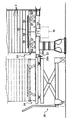
篩網を緊張させて張設した複数の篩枠を、篩網の目幅の大きい順に同一機枠内に積層して、前記機枠を鉛直な回転揺動軸によって水平面に対し回転揺動させ、粉粒体を粒径ごとに篩い分けるシフターは、例えば、図8に開示したものがある。
【0003】
図8は、シフターの外観を示すもので、複数の篩枠101をシフター機枠102上に積層してあり、積層した篩枠101と一体的にボルト103とナット104で固定したものである。篩枠101の篩網が、上段から下段にわたり徐々に網目の細かい篩網となるように積層してあり、最上段から原料の粒状物を投入し下段になるほど細かい粒子が取り出せるようにしてある。シフター機枠102はその中心位置に回転揺動する垂直な回転軸105を備え、回転軸105の回転によってシフター機枠102は水平方向に回転揺動される。シフター機枠が回転揺動すると、機枠内の篩枠101も回転揺動し、最上段の投入口106から投入される粒状物は、篩網の回転揺動と篩網目幅によって篩い分けられ、下方の排出口107から排出される。シフター機枠はその四隅をグラスファイバーロッド108などによって揺動可能に支えられている。
【0004】
従来のシフターは上記のように構成されているから、篩枠101の交換の際は、まず、シフター機枠102上に一体的に積層した篩枠101のボルト103とナット104を弛(ゆる)め、篩枠101を1枚ずつシフター機枠102の外に取り出して、篩網の破れ、張り具合、粉粒体の漏れなどを点検し、不具合があれば新しい篩枠101に交換する。そして、新しい篩枠101は、上記作業と反対に篩枠101を一枚ずつシフター機枠102内に積み重ね、所定の枚数になるとボルト103とナット104で一体的に組み付けるのである。
【0005】
以上のような篩枠101の交換作業は、篩枠の数が多くなればなる程、交換作業が重労働となる。例えば、1室あたり20〜30段の篩枠101を積層し、6室の篩分け室を有するシフターの場合、篩枠101の交換に要する作業時間は1室あたり約80分かかり、6室のシフターであれば8時間要することになり、交換作業に大変長時間を要していた。
【0006】
また、20〜30段に積み重ねた篩枠は、その高さは2〜3mであり、脚立に上っての不安定な交換作業となり、積み重ねた篩枠の崩壊の危険があった。さらに、20〜30段に積み重ねた篩枠の全体重量は200Kg程度の重量物となり、交換作業自体に危険な作業を伴っていた。
【0007】
【発明が解決しようとする課題】
本発明は上記問題点にかんがみ、篩枠交換作業における労力の負担、危険の負担を軽減し、篩枠の交換作業を容易に行うことのできるプランシフターの篩枠交換装置を提供することを技術的課題とする。
【0008】
【問題を解決するための手段】
上記課題を解決するため本発明は、目幅の異なる篩網を張設した複数の篩枠を積み重ね、これを機枠内に設けた篩分け室に収容して固定し、前記機枠を上方から吊り下げて揺動運動させて粉粒体の篩分けを行うプランシフターの篩枠交換装置であって、前記複数の篩枠を前記機枠外にてあらかじめ積み重ねて前記篩枠を一体的に保持する篩枠保持手段と、積み重ねて保持した一体的な篩枠を前記篩分け室へ収容又は篩分け室から機外に取り出すための篩枠運搬手段と、前記一体的な篩枠を前記篩分け室に収容又は機外に取り出す際に、該一体的な篩枠を前記篩分け室内で昇降させる篩枠昇降手段と、前記篩分け室に収容された前記一体的な篩枠を上方から下方へ垂直に押さえつける篩枠固定手段と、を備え、さらに、前記篩枠運搬手段が、前記一体的な篩枠を前記機枠と接する位置と前記機枠と異なる所定位置との間で移動させる第1の移動台車と、該第1の移動台車が前記機枠と接した位置にあるときに、前記一体的な篩枠を前記第1の移動台車上と前記篩分け室内との間で移動させる第2の移動台車と、から構成する、という技術的手段を講じた。
【0009】
これにより、機枠内に設けた複数の篩分け室から篩枠を取り出す際に、いちいち篩枠を1枚ずつ篩分け室から機外に取り出して、篩網の破れ、張り具合、粉粒体の漏れなどを点検し、篩枠を交換する必要がなく、篩分け室に篩枠を収容する際には、機外にて予め積み重ねた一体的篩枠の状態で篩分け室に収容することができるので、篩枠の数が多くても交換作業が楽に行える。また、多数の篩枠を積み重ねたまま一体的に機外に取り出すことができる。そして、収容された一体的篩枠を篩分け室内に固定して篩分け作業を行い、前記篩分け室から篩枠を取り出す際には、篩枠の固定を解除して積み重ねた一体的篩枠の状態で機外に取り出すことができる。例えば、1室あたり20〜30段の篩枠を積層し、6室の篩分け室を有するシフターの場合、篩枠の交換に要する作業時間は1室あたり、従来約80分かかっていたものが、半分の約40分程度で済み、6室の篩分け室を有するシフターであれば従来の半分の約4時間で済むようになった。
【0010】
また、篩枠保持手段によって、積み重ねた篩枠を一体的に保持することができ、篩枠運搬手段により機外に運び出すことが簡単に行うことができる。また、篩分け室内に篩枠を固定する際、従来は積み重ねた篩枠をボルトとナットとにより固定したのであるが、積み重ねた篩枠を篩枠固定手段により自動的に固定したり、自動的に固定を解除したりできるので、作業労力の負担が減少するようになった。
【0011】
そして、前記篩枠運搬手段が、前記一体的篩枠を前記機枠と接する位置と前記機枠と異なる所定位置との間で移動させる第1の移動台車と、該第1の移動台車が前記機枠と接した位置にあるとき、前記一体的篩枠を前記第1の移動台車上と前記篩分け室内との間で移動させる第2の移動台車とを有しているから、前記篩分け室に前記篩枠を収容する際、前記機枠と異なる所定位置に前記第1の移動台車を移動させ、該第1の移動台車上に第2の移動台車を介して前記一体的篩枠を載置し、更に、前記第1の移動台車を前記機枠と接する位置に移動させ、前記第2の移動台車を前記第1の移動台車上から前記篩分け室内へ移動させた後、第2の移動台車を取り出して篩枠を収容し、前記篩分け室から前記篩枠を取り出す際、前記第1の移動台車を前記機枠と接する位置に移動させ、前記一体的篩枠の底部に前記第2の移動台車を挿入し、該第2の移動台車を前記篩分け室内から前記第1の移動台車上へ移動させて篩枠を取り出す構成としたので、例えば、20〜30段に積み重ねた篩枠が200kg程度の重量物であっても、第1及び第2の移動台車を使用しているので、交換作業が安全であり、しかも、篩枠の交換作業が簡単で迅速に行うことができる。
【0012】
さらに、第1の移動台車により複数の篩枠を機外にて予め積み重ねて待機しておくことが可能で、第2の移動台車により一体的篩枠を篩分け室に押し込むなどの簡単な操作で篩枠を交換することができる。また、篩枠固定装置により一体的篩枠を固定したり、固定を解除したりすることが容易にでき、さらに、前記篩分け室内において前記一体的篩枠から前記第2の移動台車を抜き出す際に、前記篩枠昇降装置を作動させると、一体的篩枠を上方に浮かせて前記第2の移動台車を簡単に引っ張り出すことができる。
【0013】
請求項2記載の発明では、前記第2の移動台車が、前記一体的篩枠が載置される低い床状の台車部と、該台車部の底面に設けられた車輪とで構成され、前記篩枠昇降装置が、前記台車部とは別に前記一体的篩枠を昇降させるエアーシリンダで構成される。
【0014】
請求項3記載の発明では、前記第2の移動台車が、前記一体的篩枠が載置される底箱と、該底箱内部に設けられ、該底箱から出入り可能な車輪とで構成され、前記篩枠昇降装置が、前記底箱から出入り可能な車輪により構成される。
【0015】
請求項4記載の発明では、前記第1の移動台車が、水平調節脚及び移動キャスターを備えた脚部と、該脚部によって支持されたベース部と、支点を中心に適宜ジャッキアップすることが可能なジャッキ部と、該ジャッキ部により適宜な高さまで昇降されるリフト台と、更に、該リフト台上の水平調整部を介して設けられた載置台とで構成されるので、移動キャスターにより第1の移動台車を移動することが可能で、また、作業中は該移動台車を安定させるよう、水平調節脚を固定することが可能である。また、ジャッキ部により載置台をシフターの篩分け室の底部とほぼ同高さになるように調節できる。
【0016】
さらに、請求項5記載の発明では、前記一体的篩枠を前記篩分け室へ収容又は篩分け室から取り出す際に、前記第1の移動台車と前記篩分け室とを固定する第1のロック手段と、前記第1の移動台車と前記第2の移動手段とを固定する第2のロック手段とを設けたので、一体的篩枠の交換時には、第1及び第2の移動台車の移動が阻止されるから、例えば、20〜30段に積み重ねた一体的篩枠が200kg程度の重量物であっても安全な作業ができる。
【0017】
【発明の実施の形態】
図1は本発明のプランシフター1の全体を示す斜視図であり、図2はプランシフターの駆動部を示す概略図である。プランシフター1は篩枠2…を多数積み重ね、これを機枠4内に収容し、該機枠4を建家の天井梁からロッド5…によって吊り下げ、アンバランスウェイト7を軸着した軸6を回転させることにより、水平面で揺動運動させて篩分けを行うものである。前記軸6は機枠4内のほぼ中央に立設してあり、該軸6の機枠4内の部分にアンバランスウェイト7を軸着し(図2参照)、機枠4下部に固定したモータ8によって軸6を回転揺動させる構成になっている。符号15はモータ8のモータ軸に軸着したモータプーリであり、符号16は軸6下部に軸着した駆動プーリであり、符号17はモータプーリ15と駆動プーリ16とを連絡するベルトである。
【0018】
図1に示すプランシフター1は、機枠4内に8つの篩分け室9…が形成され、手前側の篩分け室9A,9Bについてはドア10が外され、作業者11によって篩枠の交換が行われている状態が示されている。符号12は粉粒体を各篩分け室9…に供給するため、機枠4上部に接続したインレットスリーブであり、篩分け室1室につき、3個のインレットスリーブ12が接続されている。また、符号13は篩網によって粒度別に複数種類に分級したものを排出するため、機枠4下部に接続したアウトレットスリーブである。さらに、符号14はアウトレットスリーブ13を集約するアウトレットボックスである。
【0019】
プランシフター1は、前記各篩分け室9…に複数の篩枠2…を収容して運転が開始され、メンテナンス時には、前記各篩分け室9…から複数の篩枠2…を取り出し、篩枠2…の交換などメンテナンスを行うのであるが、篩枠保持手段3及び篩枠運搬手段18を利用すると、篩枠2…の交換作業における労力の負担、危険の負担を軽減し、篩枠の交換作業を容易に行うことができる。
【0020】
図3はプランシフター1の篩枠保持手段3と篩枠運搬手段18とを示す概略縦断面図である。篩枠保持手段3は、複数の篩枠2…の四隅などを支持し、複数の篩枠2…を縦方向に積層する補強枠19…から構成される。前記補強枠19…は、例えば、軽量アルミ材などの材料で形成され、その下部を外側から縦方向に積み上げた篩枠2…の内方向へ木ネジ22…などにより取り外し可能に固定し、補強枠19の上方は最上部の篩枠2…に引っかけるカギ部23が形成され、全体がずれないように支持する。そして、篩分け室9…には、該補強枠19…とともに篩枠2…を載置する底部20と、各篩枠2…を上方から押さえつけ、各篩枠2…を密閉して粉粒体の漏出を防止するための篩枠固定装置21と、前記篩分け室9底部20に設けて、縦方向に積み上げた多数の篩枠2…を持ち上げる篩枠昇降装置30が備えられており、補強枠19とともに篩枠2…が篩分け室9…に収容されると、前記篩枠固定装置21により篩枠2…が押さえつけられることになる。
【0021】
また、篩枠運搬手段18は、積層された前記複数の篩枠2…を補強枠19ごと載置し、篩分け室9…へ収容又は篩分け室9…から移動させる転がり台車24と、更に、積層された前記複数の篩枠2…を転がり台車24ごと載置し、積層された篩枠2…をプランシフター1から離れた作業のしやすい広い場所に移動可能とする移動台車25とにより構成される。
【0022】
図4は前記転がり台車24と移動台車25を示す概略拡大図であり、転がり台車24は、篩枠2…が載置される低い床状の台車部26と、該台車部26の底面に設けられて方向性をもたず任意方向に回転可能な複数個のコロ27…と、前記台車部26の前・後部に設けられ、フォークリフトの爪を挿入することが可能な一対のフォーク孔28,28と、前記台車部26の後部26Aに設けられ、転がり台車24を前記移動台車25又は篩分け室9…の底部20に固定するためのロックピン29とから主要部が構成される。また、篩分け室9…の底部には、収容された篩枠2…の全体を上昇させる篩枠昇降装置となるエアーシリンダ30が設けられ、このエアーシリンダ30のロッド31が伸長したとき台車部26との干渉を回避するため、転がり台車24は、中央(図4にあらわれない奥行き方向)で二股に分かれている。これにより、ロッド31が伸長したとき、転がり台車24を篩分け室9…から取り出すことができる。
【0023】
篩分け室9…の底部20中央に設けたエアーシリンダ30は、そのロッド31が符号31A
へと移動して篩枠2…を持ち上げる作用をする。また、底部20の前端20Aは、前記転がり台車24のロックピン29が嵌合するピン孔32が穿設してあり、該ピン孔32の下方には、移動台車25が篩分け室9…から離れないよう、底部20の前端20Aと移動台車25の先端25Aとを接続するヒッチ33が設けられている。符号13は前述と同様のアウトレットスリーブであり、符号4は、前記軸6及びアンバランスウェイト7など駆動部を収容した機枠である。
【0024】
次に、移動台車25について説明する。移動台車25は、市販のリフターを改造したもので、水平調節脚34及び移動キャスター35を備えた脚部36…と、該脚部36…によって支持されたベース部37と、支点38を中心にネジや油圧などで適宜ジャッキアップすることが可能なジャッキ部39,39と、該ジャッキ部39,39により適宜な高さまで昇降されるリフト台40と、更に、該リフト台40上に設けた水平調整部41,41を介して設けられた載置台42とにより主要部が構成される。符号43は移動台車25が前記篩分け室9…から離れないように設けたヒッチ33に嵌合するヒッチ孔であり、符号44は転がり台車24を載置したときに前記ロックピン29が嵌合するピン孔であり、符号45は移動台車25のハンドルである。
【0025】
図5は篩分け室9に設けられた篩枠固定装置21の詳細を示す縦断面図である。篩枠固定装置21は、機枠4の上部に設けられ、機枠4上部に固定したベース部46,46,47と、該ベース部46,46と連設する少なくとも2個のガイド48,48と、各ガイド48,48により上方から下方へ垂直に挿通されるガイドシャフト49,49と、ベース部47の中心部に固定されるエアーシリンダ50などの押さえつけ手段と、前記ガイドシャフト49,49の下端49A,49Aとエアーシリンダ50のアクチュエータ51下端51Aにボルトなどで取り付けられ、篩分け室9に収容された篩枠2…を上方から下方に押圧する篩枠押さえ部52と、により構成される。該篩枠押さえ部52は、2つのガイドシャフト49,49と1つのエアーシリンダ50とにより篩枠2…を上方から下方へ垂直に押さえつけることが可能となる。
【0026】
次に、上記構成における作用を説明する。
【0027】
まず、プランシフター1の各篩分け室9…に複数の篩枠2…を収容する際の作用を説明する。図3には、前段取りとして予め必要な篩枠2…を複数個積層した様子を示してある。この作業としては、作業し易い広い場所に移動台車25を移動し、該移動台車25を安定させるよう、水平調節脚34,34を固定して、ベース部37を水平に保持する。次に、載置台42を篩分け室9の底部20とほぼ同高さになるようにジャッキ部39を調節する。そして、載置台42に転がり台車24を載せ、該転がり台車24をロックさせるためロックピン29をピン孔44に嵌合させ、転がり台車24の上に順次、複数の篩枠2…を積み上げていく。篩枠2…は、例えば、上段から下段にわたり徐々に網目の細かい篩網となるように積層していき、最上段から粒状物を投入し下段になるほど細かい粒子が取り出せるように積み上げるとよい。そして、この篩枠2…は、所定段数、例えば、30段積み上げられ、最後に補強枠19のカギ部23を最上段の篩枠2に引っかけ、全体を木ネジ22により固定する。そして、移動台車25の脚部36からから移動キャスター35を出して、積層した篩枠2…を移動台車25ごと移動可能な状態にする。
【0028】
次に、移動台車25をプランシフター1の所定の篩分け室9の前まで移動し、積層された篩枠2…を一度に交換するのである。篩分け室9に篩枠2…が収容されていないときは(図1、図3参照)、交換前の篩枠2…を取り出す必要がなく、作業者11によって篩分け室9…のドア10を外し、篩分け室9…にそのまま収容するとよい。
【0029】
さらに、図4及び図6を参照して説明する。移動台車25を篩分け室9の前まで移動させると、移動台車25の脚部36を移動キャスター35,35から水平調節脚34,34に代えて固定するとともに、移動台車25が篩分け室9…から離れないよう、ヒッチ33により底部20の前端20Aと移動台車25の先端25Aとを接続する。そして、移動台車25のジャッキ部39,39を微調整し、移動台車25の載置台42の高さを、篩分け室9…の底部20と同じ高さとなるよう調節する。そして、移動台車25のピン孔44からロックピン29を外し、篩枠2…を転がり台車24ごと篩分け室9に押し込む。
【0030】
図4では、篩分け室9の底部20に転がり台車25が載っている状態であるから、転がり台車24を篩分け室9から引っ張り出す必要がある。図6は転がり台車24を篩分け室9から引き出す様子を示す概略縦断面図である。篩枠2…が篩分け室9に収容されると、まず、エアーシリンダ30が駆動されて、ロッドが伸長する。そして、篩枠2…全体が図6上の矢印A方向に浮き上がり、篩枠2…最下部と転がり台車24との間に若干の隙間Dが生じ、この隙間Dにより、転がり台車24は篩枠2…の荷重を受けていないので、転がり台車24を矢印B方向に引っ張り出すことができる。そして、転がり台車24を篩分け室9から完全に引き出すと、エアーシリンダ30のロッド31を元の位置まで下げて篩枠2…を底部20に載置し、前記篩枠固定装置21により篩枠2…の全体を固定する。
【0031】
篩枠固定装置21は、エアーシリンダ50が作動されると、篩枠押さえ部52が、2つのガイドシャフト49,49と1つのエアーシリンダ50のアクチュエータ51とにより篩枠2…を上方から下方へ垂直に押さえつけることが可能となる。以上のように、篩枠2…の交換作業における労力は、転がり台車24及び移動台車25を使用することによって負担が大幅減少する。また、篩枠2…の交換作業は、移動台車25に設けた水平調節脚34,34により移動キャスター35による不安定さを軽減したり、ロックピン29より移動台車25と転がり台車24とを確実に固定し、また、ヒッチ33により移動台車25と篩分け室9とを確実に固定し、交換作業の危険の負担を軽減し、篩枠の交換作業を容易に行うことができる。
【0032】
さらに、従来のプランシフターと本発明のプランシフターとの篩枠の交換作業時間を比較すると以下の表のようになる。
【表1】

従来のプランシフターのように、篩枠2…を1枚ずつ機枠4の外に取り出して、篩網の破れ、張り具合、粉粒体の漏れなどを点検し、不具合があれば新しい篩枠2…に交換するものに比べ、予め篩枠2…を複数個積層した新しい篩枠2…を交換するだけでよいので、作業が簡単であり、作業時間も上記表のように大幅に削減される。
【0034】
図7は本発明の別の実施形態を示す転がり台車24と移動台車25を示す概略拡大図であり、この構成では、前述のように篩分け室9の底部20に載置した転がり台車24を篩分け室9から引っ張り出す必要がなく、上述の構成よりも更に作業時間を短縮できるものである。
【0035】
図7に示す転がり台車24は、篩枠2…が載置されるボトムボックス53と、該ボトムボックス53内部に横架したネジ軸54と、該ネジ軸54に螺合する複数のナット筒55,55と、一端を該ナット筒55,55と接続し、他端を移動キャスター56,56と接続して支点57,57を中心としてボトムボックス53から移動キャスター56,56を出入りさせるジャッキ部58,58と、前記ボトムボックス53上に載置される篩枠台59とにより構成される。符号60はネジ軸を左又は右に回転させるハンドルであり、該ハンドル60を回転することで移動キャスター56,56がボトムボックス53から出入り自在になる。
【0036】
上記構成による作用を説明する。前段取りとしては上記同様に、作業し易い広い場所に移動台車25を移動し、移動台車25上に転がり台車24を載せ、該転がり台車24の上に順次、複数の篩枠2…を積み上げていく。篩枠2…は、例えば、上段から下段にわたり徐々に網目の細かい篩網となるように積層していき、最上段から粒状物を投入し下段になるほど細かい粒子が取り出せるように積み上げるとよい。そして、この篩枠2…は、所定段数、例えば、30段積み上げられ固定する。このとき、転がり台車24が移動しないよう、ハンドル60を回転させて移動キャスター56,56がボトムボックス53へ隠れるようにする。
【0037】
次に、移動台車25をプランシフター1の所定の篩分け室9の前まで移動し、積層された篩枠2…を一度に交換するのである。このとき、転がり台車24を移動させるよう、ハンドル60を回転させて移動キャスター56,56がボトムボックス53から出没させるようにする。そして、移動台車25が篩分け室9…から離れないよう、ヒッチ33により底部20の前端20Aと移動台車25の先端25Aとを接続し、篩枠2…を転がり台車24ごと篩分け室9に押し込む。その後、転がり台車24が移動しないよう、ハンドル60を回転させて移動キャスター56,56がボトムボックス53へ隠れるようにする。なお、移動キャスター56,56を設けたボトムボックス53は前述の低い床状の台車部26とは異なり、密閉状となっているので、前記篩枠固定装置21により篩枠2…とともに固定しても粉粒体が漏出することがない。つまり、前述の台車部26のように篩分け室9からボトムボックス53を引っ張り出す必要がなく、さらに、篩枠2…の全体を上昇させるエアーシリンダ30を篩分け室9の底部20に設ける必要もなくなる。篩枠2…を篩分け室9から移動させるときは、ハンドル60を回転させて移動キャスター56,56がボトムボックス53から出没させるようにして、引っ張り出せばよい。
【0038】
【発明の効果】
以上のように本発明によれば、いちいち篩枠を1枚ずつ篩分け室から機外に取り出して、篩網の破れ、張り具合、粉粒体の漏れなどを点検し、篩枠を交換する必要がなく、多数の篩枠を積み上げたまま一体的に機外に取り出すことができ、また、篩分け室に新たな篩枠を収容する際には、機外にて予め積み上げた篩枠を一体的に収容することができるので、篩枠の数が多くても交換作業が楽に行える。例えば、1室あたり20〜30段の篩枠を積層し、6室の篩分け室を有するシフターの場合、篩枠の交換に要する作業時間は1室あたり、従来約80分かかっていたものが、半分の約40分程度で済み、6室の篩分け室を有するシフターであれば従来の半分の約4時間で済むようになった。
【0039】
また、篩枠保持手段により積み重ねた篩枠を一体的に保持することができ、篩枠運搬手段により機外に運び出すことが簡単に行うことができる。また、篩分け室内に篩枠を固定する際、従来は積み重ねた篩枠をボルトとナットとにより固定したのであるが、積み重ねた篩枠を篩枠固定手段により自動的に固定したり、自動的に固定を解除したりできるので、作業労力の負担が減少するようになった。
【0040】
前記篩枠運搬手段は、前記一体的篩枠を前記機枠と接する位置と前記機枠と異なる所定位置との間で移動させる第1の移動台車と、該第1の移動台車が前記機枠と接した位置にあるとき、前記一体的篩枠を前記第1の移動台車上と前記篩分け室内との間で移動させる第2の移動台車とを有し、前記篩分け室に前記篩枠を収容する際、前記機枠と異なる所定位置に前記第1の移動台車を移動させ、該第1の移動台車上に第2の移動台車を介して前記一体的篩枠を載置し、更に、前記第1の移動台車を前記機枠と接する位置に移動させ、前記第2の移動台車を前記第1の移動台車上から前記篩分け室内へ移動させた後、第2の移動台車を取り出して篩枠を収容し、前記篩分け室から前記篩枠を取り出す際、前記第1の移動台車を前記機枠と接する位置に移動させ、前記一体的篩枠の底部に前記第2の移動台車を挿入し、該第2の移動台車を前記篩分け室内から前記第1の移動台車上へ移動させて篩枠を取り出す構成としたので、例えば、20〜30段に積み重ねた篩枠が200kg程度の重量物であっても、第1及び第2の移動台車を使用しているので、交換作業が安全であり、しかも、篩枠の交換作業が簡単で迅速に行うことができる。
【0041】
そして、第1の移動台車により複数の篩枠を機外にて予め積み重ねて待機しておくことが可能で、第2の移動台車により一体的篩枠を篩分け室に押し込むなどの簡単な操作で篩枠を交換することができる。また、篩枠固定装置により一体的篩枠を固定したり、固定を解除したりすることが容易にでき、さらに、前記篩分け室内において前記一体的篩枠から前記第2の移動台車を抜き出す際に、前記篩枠昇降装置を作動させると、一体的篩枠を上方に浮かせて前記第2の移動台車を簡単に引っ張り出すことができる。
【0042】
また、前記第1の移動台車は、水平調節脚及び移動キャスターを備えた脚部と、該脚部によって支持されたベース部と、支点を中心に適宜ジャッキアップすることが可能なジャッキ部と、該ジャッキ部により適宜な高さまで昇降されるリフト台と、更に、該リフト台上の水平調整部を介して設けられた載置台とで構成されるので、移動キャスターにより第1の移動台車を移動することが可能で、また、作業中は該移動台車を安定させるよう、水平調節脚を固定することが可能である。また、ジャッキ部により載置台をシフターの篩分け室の底部とほぼ同高さになるように調節できる。
【図面の簡単な説明】
【図1】本発明のプランシフターの全体を示す斜視図である。
【図2】プランシフターの駆動部を示す概略図である。
【図3】プランシフターの篩枠保持手段と篩枠運搬手段とを示す概略縦断面図である。
【図4】転がり台車と移動台車を示す概略拡大図である。
【図5】篩分け室に設けられた篩枠固定装置の詳細を示す縦断面図である。
【図6】転がり台車と移動台車の作用を示す概略拡大図である。
【図7】本発明の別の実施形態を示す転がり台車と移動台車を示す概略拡大図である。
【図8】従来のシフターを示す外観図である。
【符号の説明】
1 プランシフター
2 篩枠
3 篩枠保持手段
4 機枠
5 ロッド
6 軸
7 アンバランスウェイト
8 モータ
9 篩分け室
10 ドア
11 作業者
12 インレットスリーブ
13 アウトレットスリーブ
14 アウトレットボックス
15 モータプーリ
16 駆動プーリ
17 ベルト
18 篩枠運搬手段
19 補強枠
20 底部
21 篩枠固定装置
22 木ネジ
23 カギ部
24 転がり台車
25 移動台車
26 台車部
27 コロ
28 フォーク孔
29 ロックピン
30 エアーシリンダ
31 ロッド
32 ピン孔
33 ヒッチ
34 水平調節脚
35 移動キャスター
36 脚部
37 ベース部
38 支点
39 ジャッキ部
40 リフト台
41 水平調整部
42 載置台
43 ヒッチ孔
44 ピン孔
45 ハンドル
46 ベース部
47 ベース部
48 ガイド
49 ガイドシャフト
50 エアーシリンダ
51 アクチュエータ
52 篩枠押さえ部
53 ボトムボックス
54 ネジ軸
55 ナット筒
56 移動キャスター
57 支点
58 ジャッキ部
59 篩枠台
60 ハンドル[0001]
BACKGROUND OF THE INVENTION
In the present invention, a plurality of sieve frames stretched by tensioning a sieve mesh are stacked in the same machine frame in the descending order of the mesh size of the sieve mesh, and the machine frame is placed on a horizontal plane by a vertical rotation swing shaft. In a plan shifter that rotates and swings and sifts powder particles by particle size, the sieve frame can be easily removed from the shifter machine frame during maintenance (sieve frame replacement). apparatus About.
[0002]
[Prior art]
A plurality of sieve frames stretched by tensioning the sieve mesh are stacked in the same machine frame in the order of the mesh width of the sieve mesh, and the machine frame is rotated and oscillated with respect to a horizontal plane by a vertical rotation oscillation axis. An example of a shifter for sieving powder particles for each particle size is disclosed in FIG.
[0003]
FIG. 8 shows the appearance of the shifter, in which a plurality of
[0004]
Since the conventional shifter is configured as described above, when replacing the
[0005]
The replacement work of the
[0006]
Moreover, the height of the sieving frames stacked in 20 to 30 stages was 2 to 3 m, and it was an unstable replacement work on the stepladder, and there was a risk of collapse of the stacked sieving frames. Furthermore, the total weight of the sieving frames stacked in 20 to 30 stages is a heavy article of about 200 kg, and the replacement work itself involves a dangerous work.
[0007]
[Problems to be solved by the invention]
In view of the above-mentioned problems, the present invention reduces the burden of labor and risk in the replacement of the sieve frame, and facilitates the replacement of the sieve frame. Exchange device It is a technical challenge to provide
[0008]
[Means for solving problems]
In order to solve the above-mentioned problems, the present invention stacks a plurality of sieving frames provided with sieving screens having different mesh widths, accommodates them in a sieving chamber provided in the machine frame, and fixes the machine frame upward. Plan shifter that screens powder particles by swinging and suspending Sieve frame changer And the plurality of sieve frames In advance outside the machine frame Pile up The sieve frame Sieving frame holding means for holding integrally, sieving frame transporting means for storing the integrated sieving frames stacked and held in the sieving chamber or taking them out of the sieving chamber, and the integrated sieving frame When the sieving chamber is accommodated or taken out of the machine, the sieving frame lifting means for raising and lowering the integral sieving frame in the sieving chamber; and the integral sieving frame accommodated in the sieving chamber. Sieving frame fixing means for vertically pressing from above to below Furthermore, the first moving carriage moves the first sieve frame between a position in contact with the machine frame and a predetermined position different from the machine frame, and the first moving carriage. A second moving carriage that moves the integral sieve frame between the first moving carriage and the sieving chamber when the machine is in a position in contact with the machine frame. Technical measures were taken.
[0009]
As a result, when the sieving frames are taken out from the plurality of sieving chambers provided in the machine frame, the sieving frames are taken out from the sieving chamber one by one from the sieving chamber one by one. There is no need to check for leaks and replace the sieving frame. When the sieving frame is stored in the sieving chamber, it must be stored in the sieving chamber in the state of an integrated sieving frame that has been stacked in advance outside the machine. Therefore, even if there are many sieve frames, replacement work can be performed easily. In addition, a large number of sieve frames can be integrally removed outside the machine. Then, the contained integral sieving frame is fixed in the sieving chamber to perform sieving work, and when the sieving frame is taken out from the sieving chamber, the sieving frame is fixed and stacked. Can be taken out of the machine. For example, in the case of a shifter having six to thirty sieving frames stacked per room and having six sieving chambers, the work time required to replace the sieving frame is conventionally about 80 minutes per room. The shifter having six sieving chambers can be completed in about 40 minutes, which is about half an hour.
[0010]
Also , The stacked sieve frames can be held integrally by the sieve frame holding means, and can be easily carried out of the apparatus by the sieve frame carrying means. In addition, when the sieve frame is fixed in the sieving chamber, the stacked sieve frame is conventionally fixed with bolts and nuts, but the stacked sieve frame is automatically fixed by the sieve frame fixing means or automatically. It is now possible to release the fixing, so the burden of work labor has been reduced.
[0011]
And The sieve frame carrying means But A first moving carriage that moves the integral sieve frame between a position in contact with the machine frame and a predetermined position different from the machine frame, and the first moving carriage is in a position in contact with the machine frame. And a second moving carriage for moving the integral sieve frame between the first moving carriage and the sieving chamber. Because When accommodating the sieving frame in the sieving chamber, the first moving carriage is moved to a predetermined position different from the machine frame, and the integrated movement is carried out on the first moving carriage via the second moving carriage. After placing a sieve frame, and further moving the first movable carriage to a position in contact with the machine frame and moving the second movable carriage from the first movable carriage into the sieving chamber The second movable carriage is taken out to accommodate the sieve frame, and when the sieve frame is taken out from the sieving chamber, the first movable carriage is moved to a position in contact with the machine frame, and the integral sieve frame Since the second movable carriage is inserted into the bottom, the second movable carriage is moved from the sieving chamber onto the first movable carriage, and the sieve frame is taken out. 1st and 2nd moving carts are used even if the sieve frames stacked on top are heavy objects of about 200kg Since the are, the exchange work is safe, moreover, can be performed in a quick and easy replacement of the sieve frame.
[0012]
further, A plurality of sieving frames can be stacked in advance outside the machine by the first moving carriage, and the sieving can be performed by a simple operation such as pushing the integral sieving frame into the sieving chamber by the second moving carriage. The frame can be exchanged. In addition, the integral sieve frame can be easily fixed or released by the sieve frame fixing device, and when the second movable carriage is extracted from the integral sieve frame in the sieving chamber. Further, when the sieve frame lifting device is operated, the integral sieve frame can be lifted upward and the second movable carriage can be easily pulled out.
[0013]
[0014]
[0015]
[0016]
further,
[0017]
DETAILED DESCRIPTION OF THE INVENTION
FIG. 1 is a perspective view showing the entire plan shifter 1 of the present invention, and FIG. 2 is a schematic view showing a drive unit of the plan shifter. The plan shifter 1 stacks a large number of sieve frames 2. The plan shifter 1 accommodates the sieve frames 2 in the
[0018]
In the plan shifter 1 shown in FIG. 1, eight sieving chambers 9 are formed in the
[0019]
The plan shifter 1 is operated by accommodating a plurality of sieving
[0020]
FIG. 3 is a schematic longitudinal sectional view showing the sieve frame holding means 3 and the sieve frame carrying means 18 of the plan shifter 1. The sieve frame holding means 3 is composed of reinforcing
[0021]
Further, the sieving frame transporting means 18 places the plurality of stacked sieving frames 2 together with the reinforcing
[0022]
FIG. 4 is a schematic enlarged view showing the rolling
[0023]
The
It moves to and lifts the
[0024]
Next, the
[0025]
FIG. 5 is a longitudinal sectional view showing details of the sieve
[0026]
Next, the operation of the above configuration will be described.
[0027]
First, the operation when the plurality of sieving
[0028]
Next, the
[0029]
Further description will be made with reference to FIGS. When the
[0030]
In FIG. 4, since the rolling
[0031]
When the
[0032]
Furthermore, when the replacement work time of the sieve frame of the conventional plan shifter and the plan shifter of the present invention is compared, the following table is obtained.
[Table 1]
Like the conventional plan shifter, take the sieve frames 2 out of the
[0034]
FIG. 7 is a schematic enlarged view showing a rolling
[0035]
A rolling
[0036]
The operation of the above configuration will be described. As in the previous setup, the moving
[0037]
Next, the
[0038]
【The invention's effect】
As described above, according to the present invention, , Take out the sieve frames one by one from the sieving chamber one by one, check for broken sieve nets, tension, and leakage of granular materials, and do not need to replace the sieve frames. It can be taken out of the machine as it is, and when a new sieve frame is accommodated in the sieving chamber, the sieve frame previously stacked outside the machine can be accommodated integrally. Even if there are many sieve frames, replacement work can be performed easily. For example, in the case of a shifter having six to thirty sieving frames stacked per room and having six sieving chambers, the work time required to replace the sieving frame is conventionally about 80 minutes per room. The shifter having six sieving chambers can be completed in about 40 minutes, which is about half an hour.
[0039]
Also , The sieve frames stacked by the sieve frame holding means can be held integrally, and can be easily carried out of the machine by the sieve frame carrying means. In addition, when the sieve frame is fixed in the sieving chamber, the stacked sieve frame is conventionally fixed with bolts and nuts, but the stacked sieve frame is automatically fixed by the sieve frame fixing means or automatically. It is now possible to release the fixing, so the burden of work labor has been reduced.
[0040]
The sieve frame carrying means includes a first moving carriage that moves the integral sieve frame between a position in contact with the machine frame and a predetermined position different from the machine frame, and the first movable carriage is the machine frame. A second moving carriage that moves the integral sieving frame between the first moving carriage and the sieving chamber when in a position in contact with the sieving chamber, The first movable carriage is moved to a predetermined position different from the machine frame, and the integral sieve frame is placed on the first movable carriage via the second movable carriage. The first movable carriage is moved to a position in contact with the machine frame, the second movable carriage is moved from the first movable carriage into the sieving chamber, and then the second movable carriage is taken out. When the sieving frame is accommodated and the sieving frame is taken out from the sieving chamber, the first movable carriage is brought into contact with the machine frame. The second movable carriage is inserted into the bottom of the integral sieve frame, and the second movable carriage is moved from the sieving chamber onto the first movable carriage to take out the sieve frame. Since it is configured, for example, even if the sieve frames stacked in 20 to 30 stages are heavy items of about 200 kg, the replacement work is safe because the first and second movable carriages are used. The sieve frame can be exchanged easily and quickly.
[0041]
And It is possible to stack a plurality of sieve frames in advance by the first moving carriage in advance and stand by, and with a simple operation such as pushing the integral sieve frame into the sieving chamber by the second moving carriage. The sieve frame can be replaced. In addition, the integral sieve frame can be easily fixed or released by the sieve frame fixing device, and when the second movable carriage is extracted from the integral sieve frame in the sieving chamber. Further, when the sieve frame lifting device is operated, the integral sieve frame can be lifted upward and the second movable carriage can be easily pulled out.
[0042]
Further, the first moving carriage includes a leg portion including a leveling leg and a moving caster, a base portion supported by the leg portion, and a jack portion that can be appropriately jacked up around a fulcrum, Since it is composed of a lift base that is raised and lowered to an appropriate height by the jack part and a mounting base provided via a level adjustment part on the lift base, the first movable carriage is moved by a moving caster. The leveling legs can be fixed to stabilize the moving carriage during work. Moreover, it can adjust so that a mounting base may become substantially the same height as the bottom part of the sifting chamber of a shifter with a jack part.
[Brief description of the drawings]
FIG. 1 is a perspective view showing the entire plan shifter of the present invention.
FIG. 2 is a schematic diagram showing a driving unit of a plan shifter.
FIG. 3 is a schematic longitudinal sectional view showing a sieve frame holding means and a sieve frame carrying means of the plan shifter.
FIG. 4 is a schematic enlarged view showing a rolling carriage and a moving carriage.
FIG. 5 is a longitudinal sectional view showing details of a sieving frame fixing device provided in the sieving chamber.
FIG. 6 is a schematic enlarged view showing the operation of a rolling carriage and a moving carriage.
FIG. 7 is a schematic enlarged view showing a rolling carriage and a moving carriage showing another embodiment of the present invention.
FIG. 8 is an external view showing a conventional shifter.
[Explanation of symbols]
1 Plan shifter
2 sieve frame
3 Sieve frame holding means
4 Machine frame
5 Rod
6 axes
7 Unbalanced weight
8 Motor
9 Sieving room
10 Door
11 Worker
12 Inlet sleeve
13 Outlet sleeve
14 Outlet box
15 Motor pulley
16 Drive pulley
17 Belt
18 Sieve frame transport means
19 Reinforcement frame
20 Bottom
21 Sieve frame fixing device
22 Wood screw
23 key
24 Rolling cart
25 Moving cart
26 Bogie parts
27 Roll
28 Fork hole
29 Lock pin
30 Air cylinder
31 Rod
32 pin hole
33 Hitch
34 Leveling feet
35 moving casters
36 legs
37 Base part
38 fulcrum
39 Jack
40 Lift stand
41 Leveling section
42 mounting table
43 Hitch hole
44 pin hole
45 Handle
46 Base part
47 Base part
48 Guide
49 Guide shaft
50 Air cylinder
51 Actuator
52 Sieve frame retainer
53 Bottom Box
54 Screw shaft
55 Nut cylinder
56 Moving caster
57 fulcrum
58 Jack
59 Sieve frame stand
60 handle
Claims (5)
前記複数の篩枠を前記機枠外にてあらかじめ積み重ねて前記篩枠を一体的に保持する篩枠保持手段と、
積み重ねて保持した一体的な篩枠を前記篩分け室へ収容又は篩分け室から機外に取り出すための篩枠運搬手段と、
前記一体的な篩枠を前記篩分け室に収容又は機外に取り出す際に、該一体的な篩枠を前記篩分け室内で昇降させる篩枠昇降手段と、
前記篩分け室に収容された前記一体的な篩枠を上方から下方へ垂直に押さえつける篩枠固定手段と、を備え、さらに、
前記篩枠運搬手段が、前記一体的な篩枠を前記機枠と接する位置と前記機枠と異なる所定位置との間で移動させる第1の移動台車と、該第1の移動台車が前記機枠と接した位置にあるときに、前記一体的な篩枠を前記第1の移動台車上と前記篩分け室内との間で移動させる第2の移動台車と、から構成されることを特徴とするプランシフターの篩枠交換装置。A plurality of sieve frames with different mesh widths are piled up, accommodated in a sieving chamber provided in the machine frame and fixed, and the machine frame is suspended from above and swung to make a powder. A sieving frame exchange device for a plan shifter for sieving granules,
A sieve frame holding means for stacking the plurality of sieve frames in advance outside the machine frame and holding the sieve frames integrally;
A sieving frame conveying means for storing and holding the integrated sieving frame in the sieving chamber or taking it out of the sieving chamber;
When the integral sieve frame is accommodated in the sieving chamber or taken out of the machine, the sieving frame lifting means for raising and lowering the integral sieving frame in the sieving chamber;
Sieving frame fixing means for vertically pressing the integral sieving frame accommodated in the sieving chamber from above to below , and
The sieving frame transporting means moves the integral sieving frame between a position in contact with the machine frame and a predetermined position different from the machine frame, and the first moving carriage is the machine. A second movable carriage that moves the integral sieve frame between the first movable carriage and the sieving chamber when in a position in contact with the frame ; Plan shifter sieve frame changing device.
Priority Applications (6)
| Application Number | Priority Date | Filing Date | Title |
|---|---|---|---|
| JP28870599A JP4374603B2 (en) | 1999-10-08 | 1999-10-08 | Plan shifter sieve frame changer |
| CA002321374A CA2321374C (en) | 1999-10-08 | 2000-09-27 | Method and apparatus for exchanging sifter frames of a plan sifter |
| US09/679,392 US6431367B1 (en) | 1999-10-08 | 2000-10-03 | Method and apparatus for exchanging sifter frames of a plan sifter |
| EP00308785A EP1090691B1 (en) | 1999-10-08 | 2000-10-05 | Method and apparatus for exchanging sifter frames of a plan sifter |
| DE60027836T DE60027836T2 (en) | 1999-10-08 | 2000-10-05 | Method and device for changing sieve boxes in a plan sifter |
| AU62526/00A AU776040B2 (en) | 1999-10-08 | 2000-10-06 | Method and apparatus for exchanging sifter frames of a plan sifter |
Applications Claiming Priority (1)
| Application Number | Priority Date | Filing Date | Title |
|---|---|---|---|
| JP28870599A JP4374603B2 (en) | 1999-10-08 | 1999-10-08 | Plan shifter sieve frame changer |
Publications (3)
| Publication Number | Publication Date |
|---|---|
| JP2001104885A JP2001104885A (en) | 2001-04-17 |
| JP2001104885A5 JP2001104885A5 (en) | 2006-11-02 |
| JP4374603B2 true JP4374603B2 (en) | 2009-12-02 |
Family
ID=17733629
Family Applications (1)
| Application Number | Title | Priority Date | Filing Date |
|---|---|---|---|
| JP28870599A Expired - Fee Related JP4374603B2 (en) | 1999-10-08 | 1999-10-08 | Plan shifter sieve frame changer |
Country Status (6)
| Country | Link |
|---|---|
| US (1) | US6431367B1 (en) |
| EP (1) | EP1090691B1 (en) |
| JP (1) | JP4374603B2 (en) |
| AU (1) | AU776040B2 (en) |
| CA (1) | CA2321374C (en) |
| DE (1) | DE60027836T2 (en) |
Families Citing this family (10)
| Publication number | Priority date | Publication date | Assignee | Title |
|---|---|---|---|---|
| US6808356B2 (en) * | 2000-12-28 | 2004-10-26 | Toyota Steel Center Co., Ltd. | Device for carrying article into and from container, method for introducing and discharging article into and from container, and pallet for carrying article |
| GB2419308A (en) * | 2004-10-14 | 2006-04-26 | Satake Eng Co Ltd | Sieve frame with labyrinth seal |
| DE102007004150A1 (en) * | 2007-01-22 | 2008-07-24 | Bühler AG | Plansichter |
| EP2520376A1 (en) * | 2011-05-03 | 2012-11-07 | Bühler AG | Method and device for fractionation of bulk goods |
| JP5636071B1 (en) * | 2013-06-06 | 2014-12-03 | 明治機械株式会社 | Screening machine, elevating frame used therefor, and method for fixing the screen |
| US10654504B1 (en) * | 2019-03-07 | 2020-05-19 | Dishcraft Robotics, Inc. | Dish stacking cart |
| KR20210149820A (en) | 2019-04-12 | 2021-12-09 | 가부시끼가이샤 사따께 | Operation monitoring system of sieving device |
| JP7367330B2 (en) | 2019-04-12 | 2023-10-24 | 株式会社サタケ | Operation monitoring system for sieving equipment |
| USD949218S1 (en) * | 2020-06-30 | 2022-04-19 | Bühler AG | Plan sifter |
| CN112495789A (en) * | 2020-10-29 | 2021-03-16 | 德清凯晶光电科技有限公司 | Crop seed screening installation of gradable screening |
Family Cites Families (8)
| Publication number | Priority date | Publication date | Assignee | Title |
|---|---|---|---|---|
| CH547129A (en) * | 1972-01-20 | 1974-03-29 | Buehler Ag Geb | PLANSIFTER. |
| CH631092A5 (en) * | 1978-05-02 | 1982-07-30 | Buehler Ag Geb | FREE-SWINGING PLANNERS. |
| JPH0215983A (en) * | 1988-06-30 | 1990-01-19 | Aichi Steel Works Ltd | Work mounting and demounting device |
| ES2021928A6 (en) * | 1989-12-27 | 1991-11-16 | Daumar Talleres | Machine for filling receptacles with products in accordance with a predetermined pattern. |
| US5387063A (en) * | 1992-04-15 | 1995-02-07 | American Sterilizer Company | Indirect lock and lock release mechanism |
| US5595470A (en) * | 1994-03-07 | 1997-01-21 | American Airlines, Incorporated | Lift for physically-challenged passengers and method of operation |
| US5641260A (en) * | 1995-04-13 | 1997-06-24 | Gray; Stephen Jay | Shaft coupling device and locking mechanism |
| US6036126A (en) * | 1998-12-09 | 2000-03-14 | Boehringer Ingelheim Pharmaceuticals, Inc. | Apparatus for separating particles of cohesive material according to size and process |
-
1999
- 1999-10-08 JP JP28870599A patent/JP4374603B2/en not_active Expired - Fee Related
-
2000
- 2000-09-27 CA CA002321374A patent/CA2321374C/en not_active Expired - Fee Related
- 2000-10-03 US US09/679,392 patent/US6431367B1/en not_active Expired - Fee Related
- 2000-10-05 DE DE60027836T patent/DE60027836T2/en not_active Expired - Lifetime
- 2000-10-05 EP EP00308785A patent/EP1090691B1/en not_active Expired - Lifetime
- 2000-10-06 AU AU62526/00A patent/AU776040B2/en not_active Ceased
Also Published As
| Publication number | Publication date |
|---|---|
| US6431367B1 (en) | 2002-08-13 |
| CA2321374A1 (en) | 2001-04-08 |
| DE60027836D1 (en) | 2006-06-14 |
| EP1090691A2 (en) | 2001-04-11 |
| AU776040B2 (en) | 2004-08-26 |
| EP1090691A3 (en) | 2002-11-27 |
| EP1090691B1 (en) | 2006-05-10 |
| JP2001104885A (en) | 2001-04-17 |
| AU6252600A (en) | 2001-04-12 |
| DE60027836T2 (en) | 2006-11-30 |
| CA2321374C (en) | 2008-11-18 |
Similar Documents
| Publication | Publication Date | Title |
|---|---|---|
| JP4374603B2 (en) | Plan shifter sieve frame changer | |
| US20090232634A1 (en) | Method and a device for lifting and rotating a massive container | |
| US3871477A (en) | Sheetrock lift and scaffold | |
| CN110304319B (en) | Double-station electric hoisting ton bag opening station and working method thereof | |
| KR101711883B1 (en) | working lift | |
| KR100710748B1 (en) | Multi function working table | |
| KR102279414B1 (en) | An electric gantry crane assembly | |
| JP2001104885A5 (en) | ||
| CN106006482B (en) | A kind of hand steered fork truck of lightweight | |
| GB2154643A (en) | Plant for transporting and installing of building elements | |
| CN212374140U (en) | Commodity circulation is deposited and is lifted device with goods | |
| JPS5851508B2 (en) | Goods conveyance intermediary device | |
| CN206088942U (en) | Hand fork truck of lightweight | |
| JP3429144B2 (en) | Plate-shaped transport cart | |
| KR101797479B1 (en) | Turn over apparatus with double turning ring for turning over propeller of ship | |
| CN213865279U (en) | Fire control lift objective table with mechanism subtracts width of cloth | |
| CN217835714U (en) | Handcart convenient to unload | |
| JPH0848493A (en) | Shifting truck device for simple lift | |
| JP2956918B2 (en) | Forming panel sorting device | |
| CN213894993U (en) | Lifting appliance vehicle device for replacing injection rod of high-pressure casting machine | |
| JP3517871B2 (en) | Method and apparatus for transporting heavy box | |
| CN211735050U (en) | Bridge inspection vehicle and stabilizer locking device thereof | |
| CN212533761U (en) | Bridge construction equipment | |
| CN220502620U (en) | Tilting type hydraulic lifter | |
| CN218560400U (en) | Yardage roll lifting machine |
Legal Events
| Date | Code | Title | Description |
|---|---|---|---|
| A521 | Written amendment |
Free format text: JAPANESE INTERMEDIATE CODE: A523 Effective date: 20060919 |
|
| A621 | Written request for application examination |
Free format text: JAPANESE INTERMEDIATE CODE: A621 Effective date: 20060919 |
|
| A977 | Report on retrieval |
Free format text: JAPANESE INTERMEDIATE CODE: A971007 Effective date: 20080624 |
|
| A131 | Notification of reasons for refusal |
Free format text: JAPANESE INTERMEDIATE CODE: A131 Effective date: 20090602 |
|
| A521 | Written amendment |
Free format text: JAPANESE INTERMEDIATE CODE: A523 Effective date: 20090727 |
|
| TRDD | Decision of grant or rejection written | ||
| A01 | Written decision to grant a patent or to grant a registration (utility model) |
Free format text: JAPANESE INTERMEDIATE CODE: A01 Effective date: 20090817 |
|
| A01 | Written decision to grant a patent or to grant a registration (utility model) |
Free format text: JAPANESE INTERMEDIATE CODE: A01 |
|
| A61 | First payment of annual fees (during grant procedure) |
Free format text: JAPANESE INTERMEDIATE CODE: A61 Effective date: 20090830 |
|
| R150 | Certificate of patent or registration of utility model |
Ref document number: 4374603 Country of ref document: JP Free format text: JAPANESE INTERMEDIATE CODE: R150 Free format text: JAPANESE INTERMEDIATE CODE: R150 |
|
| FPAY | Renewal fee payment (event date is renewal date of database) |
Free format text: PAYMENT UNTIL: 20120918 Year of fee payment: 3 |
|
| FPAY | Renewal fee payment (event date is renewal date of database) |
Free format text: PAYMENT UNTIL: 20120918 Year of fee payment: 3 |
|
| FPAY | Renewal fee payment (event date is renewal date of database) |
Free format text: PAYMENT UNTIL: 20120918 Year of fee payment: 3 |
|
| FPAY | Renewal fee payment (event date is renewal date of database) |
Free format text: PAYMENT UNTIL: 20120918 Year of fee payment: 3 |
|
| FPAY | Renewal fee payment (event date is renewal date of database) |
Free format text: PAYMENT UNTIL: 20120918 Year of fee payment: 3 |
|
| FPAY | Renewal fee payment (event date is renewal date of database) |
Free format text: PAYMENT UNTIL: 20130918 Year of fee payment: 4 |
|
| R250 | Receipt of annual fees |
Free format text: JAPANESE INTERMEDIATE CODE: R250 |
|
| R250 | Receipt of annual fees |
Free format text: JAPANESE INTERMEDIATE CODE: R250 |
|
| R250 | Receipt of annual fees |
Free format text: JAPANESE INTERMEDIATE CODE: R250 |
|
| R250 | Receipt of annual fees |
Free format text: JAPANESE INTERMEDIATE CODE: R250 |
|
| R250 | Receipt of annual fees |
Free format text: JAPANESE INTERMEDIATE CODE: R250 |
|
| R250 | Receipt of annual fees |
Free format text: JAPANESE INTERMEDIATE CODE: R250 |
|
| R250 | Receipt of annual fees |
Free format text: JAPANESE INTERMEDIATE CODE: R250 |
|
| LAPS | Cancellation because of no payment of annual fees |