JP4369613B2 - Magnetic resonance imaging system - Google Patents
Magnetic resonance imaging system Download PDFInfo
- Publication number
- JP4369613B2 JP4369613B2 JP2000352019A JP2000352019A JP4369613B2 JP 4369613 B2 JP4369613 B2 JP 4369613B2 JP 2000352019 A JP2000352019 A JP 2000352019A JP 2000352019 A JP2000352019 A JP 2000352019A JP 4369613 B2 JP4369613 B2 JP 4369613B2
- Authority
- JP
- Japan
- Prior art keywords
- magnetic field
- resonance imaging
- imaging apparatus
- magnetic resonance
- gradient
- Prior art date
- Legal status (The legal status is an assumption and is not a legal conclusion. Google has not performed a legal analysis and makes no representation as to the accuracy of the status listed.)
- Expired - Fee Related
Links
- 238000002595 magnetic resonance imaging Methods 0.000 title claims description 38
- 230000005291 magnetic effect Effects 0.000 claims description 147
- 239000000463 material Substances 0.000 claims description 58
- 230000003068 static effect Effects 0.000 claims description 28
- 230000001629 suppression Effects 0.000 claims description 28
- 125000006850 spacer group Chemical group 0.000 claims description 18
- 230000035699 permeability Effects 0.000 claims description 7
- 230000003014 reinforcing effect Effects 0.000 claims description 6
- 238000012937 correction Methods 0.000 claims description 5
- 238000003384 imaging method Methods 0.000 claims description 5
- 230000002093 peripheral effect Effects 0.000 claims description 5
- 229910000976 Electrical steel Inorganic materials 0.000 claims description 4
- 229910001035 Soft ferrite Inorganic materials 0.000 claims description 3
- 239000003302 ferromagnetic material Substances 0.000 claims description 2
- 230000005294 ferromagnetic effect Effects 0.000 claims 1
- XEEYBQQBJWHFJM-UHFFFAOYSA-N Iron Chemical compound [Fe] XEEYBQQBJWHFJM-UHFFFAOYSA-N 0.000 description 10
- 239000012779 reinforcing material Substances 0.000 description 8
- 238000010586 diagram Methods 0.000 description 6
- 229910052742 iron Inorganic materials 0.000 description 5
- 239000000696 magnetic material Substances 0.000 description 5
- 238000012986 modification Methods 0.000 description 5
- 230000004048 modification Effects 0.000 description 5
- 230000000694 effects Effects 0.000 description 4
- 238000013459 approach Methods 0.000 description 2
- 238000009826 distribution Methods 0.000 description 2
- 230000004907 flux Effects 0.000 description 2
- 238000012545 processing Methods 0.000 description 2
- 230000002411 adverse Effects 0.000 description 1
- 239000002131 composite material Substances 0.000 description 1
- 239000004020 conductor Substances 0.000 description 1
- 238000007796 conventional method Methods 0.000 description 1
- 238000013461 design Methods 0.000 description 1
- 238000003754 machining Methods 0.000 description 1
- 238000004519 manufacturing process Methods 0.000 description 1
- 238000000034 method Methods 0.000 description 1
- 238000005457 optimization Methods 0.000 description 1
- 230000000452 restraining effect Effects 0.000 description 1
- 238000004088 simulation Methods 0.000 description 1
- 238000012360 testing method Methods 0.000 description 1
Images


Classifications
-
- G—PHYSICS
- G01—MEASURING; TESTING
- G01R—MEASURING ELECTRIC VARIABLES; MEASURING MAGNETIC VARIABLES
- G01R33/00—Arrangements or instruments for measuring magnetic variables
- G01R33/20—Arrangements or instruments for measuring magnetic variables involving magnetic resonance
- G01R33/28—Details of apparatus provided for in groups G01R33/44 - G01R33/64
- G01R33/38—Systems for generation, homogenisation or stabilisation of the main or gradient magnetic field
- G01R33/383—Systems for generation, homogenisation or stabilisation of the main or gradient magnetic field using permanent magnets
-
- G—PHYSICS
- G01—MEASURING; TESTING
- G01R—MEASURING ELECTRIC VARIABLES; MEASURING MAGNETIC VARIABLES
- G01R33/00—Arrangements or instruments for measuring magnetic variables
- G01R33/20—Arrangements or instruments for measuring magnetic variables involving magnetic resonance
- G01R33/44—Arrangements or instruments for measuring magnetic variables involving magnetic resonance using nuclear magnetic resonance [NMR]
- G01R33/48—NMR imaging systems
- G01R33/54—Signal processing systems, e.g. using pulse sequences ; Generation or control of pulse sequences; Operator console
- G01R33/56—Image enhancement or correction, e.g. subtraction or averaging techniques, e.g. improvement of signal-to-noise ratio and resolution
- G01R33/565—Correction of image distortions, e.g. due to magnetic field inhomogeneities
- G01R33/56518—Correction of image distortions, e.g. due to magnetic field inhomogeneities due to eddy currents, e.g. caused by switching of the gradient magnetic field
Description
【0001】
【発明の属する技術分野】
本発明は、生体組織を画像化する磁気共鳴イメージング装置に係り、特にイメージング撮影の行われる磁場領域の均一度を向上させる磁場の発生方式に改良を加えた磁気共鳴イメージング装置に関する。
【0002】
【従来の技術】
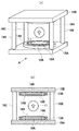
生体組織を画像化する磁気共鳴イメージング装置(以下「MRI」とする)には、超電導コイルを用いて静磁場を発生するものがある。図1は、超電導コイルを用いた従来のMRI装置の一例を示す図である。図1(a)は、MRI装置の概略を示す外観図、図1(b)は図1(a)のA視断面図である。この装置は、上下方向に対向して配置された2組の超電導コイル13A,13Bによって静磁場を発生させる。超電導コイル13A,13Bは、上下方向に対向して設けられた磁気プレート15A,15Bによって支持される。磁気プレート15A,15Bの間は柱状継鉄16A〜16Dによって機械的に支持されている。超電導コイル13A,13Bの内側には良好な磁場均一度を得るための鉄で構成されたポールピース14A,14Bが設けられ、超電導コイル13A,13Bと共に磁気プレート15A,15Bによって支持される。ポールピース14A,14Bは、均一磁場領域11の磁場均一度を向上させる働きをする。磁気プレート15A,15Bと柱状継鉄16A〜16Dは、超電導コイル13A,13Bが発生する磁束の磁路としての役割を兼ねている。
【0003】
このような構成のMRI装置では、磁気回路は、超電導コイル13B、ポールピース14B、均一磁場領域11、ポールピース14A、超電導コイル13A、磁気プレート15A、柱状継鉄16A〜16D、磁気プレート15Bの経路で形成され、均一磁場領域11には上下方向の均一な垂直磁場が発生するようになっている。従って、磁気共鳴イメージング撮影はこの均一磁場領域11内にて行われる。この磁気回路で使用される傾斜磁場コイル18A,18Bは、図1(b)に示すような平板形状をしており、均一磁場領域11を挟んで上下に対向して配置されている。この傾斜磁場コイル18A,18Bは、図1(b)に示すように、ポールピース14A,14Bの凹部内に収容されている。
【0004】
この傾斜磁場コイル18A,18Bによってポールピース14A,14Bや超電導コイル13A,13Bの導体部などに、渦電流や残留磁場が発生し、画像に大きな悪影響を与えることが知られている。そこで、渦電流や残留磁場が発生するのを防止するために、ポールピース14A,14Bの凹部内表面に、低渦電流材や高透磁率材などの渦電流抑制材19A,19Bを配置したものが知られている。例えば、ポールピース14A,14Bの凹部内表面に高透磁率材による渦電流抑制材を備えたものが米国特許第5,061,897号公報に記載されている。また、ポールピース14A,14Bの凹部内表面に珪素鋼板を積層一体化した複数ブロックを設けたものが特開平9−117431号公報(公報での実施例は永久磁石を磁性発生源として説明)に記載されている。さらに、ポールピース14A,14Bの凹部内表面を高透磁率磁性材料と磁性複合材料で構成し、かつ高透磁率磁性材料を空隙に面する位置に配置したものが特開平1−86954号公報に記載されている。
【0005】
【発明が解決しようとする課題】
上述の従来技術はいずれも均一磁場領域11における磁場の均一性を調整するために、ポールピースの凹部内の表面を加工することについては言及していない。それは、ポールピースの凹部内の表面に設けられた低渦電流材や高透磁率材は、一般的に機械的な加工が難しく、精密な加工精度を得ることができず、加工したとしても高いコストがかかるという問題があるからである。なお、特開平9−117431号公報に記載されたものは、ブロック厚さを調整することによって、ポールピースの中央部分に円形上の凸部や断面台形状の突起部を設け、磁場の均一性を高めようとしているが、これでは磁場均一性を高精度に調整することは極めて困難である。
【0006】
本発明の目的は、傾斜磁場コイルによって発生する渦電流や残留磁場の影響を抑制すると共に均一磁場領域の均一性を高めることのできる磁気共鳴イメージング装置を提供することにある。
【0007】
【課題を解決するための手段】
請求項1に係る磁気共鳴イメージング装置は、対向して設けられ、その対向空間内に静磁場を発生させる静磁場発生手段と、前記静磁場領域における静磁場の均一性を高める磁場補正手段と、前記静磁場領域に傾斜磁場を発生させる傾斜磁場発生手段と、前記静磁場発生手段及び磁場補正手段を保持する磁気プレート手段とを備えた磁気共鳴イメージング装置において、前記傾斜磁場発生手段の発生する傾斜磁場の影響を遮蔽する平板状の抑制手段を前記傾斜磁場発生手段と前記磁気プレート手段との間に設け、前記静磁場領域における静磁場の均一性をより高めるような断面形状をした均一度制御手段を前記抑制手段と前記磁気プレート手段との間に設けたものである。抑制手段は、傾斜磁場発生手段の発生する傾斜磁場による渦電流や残留磁場による影響を磁気プレート手段などに与えないようにするものであり、珪素鋼板やソフトフェライトなどの低渦電流材や高透磁率材の平板材で構成される。一方、均一度制御手段は、静磁場領域における静磁場の均一性を高めるような断面形状に加工しやすい鉄などで構成されている。抑制手段は平板材で構成されているので、傾斜磁場発生手段の形状に合わせて切り取るだけなので製作が容易である。また、抑制手段が設けられているので、均一度制御手段を設けた場合でも、傾斜磁場発生手段による渦電流や残留磁場による影響が均一度制御手段に現れることもない。
【0008】
請求項2に係る磁気共鳴イメージング装置は、請求項1において、さらに、前記抑制手段と前記均一度制御手段との間の空間にスペーサ手段を設けたものである。スペーサ手段を設けることによって、抑制手段を精度よく、かつ堅固に固定することができる。
【0009】
請求項3に係る磁気共鳴イメージング装置は、請求項2において、さらに、前記抑制手段と前記スペーサ手段との間に前記抑制手段を補強するための補強手段を設けたものである。抑制手段は、珪素鋼板やソフトフェライト等の小片をほぼ平面形状に貼り合わせたもので構成されるので、機械的な強度を得ることが難しい。そこで、抑制手段と均一度制御手段との間にスペーサ手段及び補強材手段を設けることによって、抑制手段の機械的強度を十分な大きさにする。
【0010】
【発明の実施の形態】
以下添付図面に従って本発明に係る磁気共鳴イメージング装置の好ましい実施の形態について説明する。
図2は、本発明に係るMRI装置の概略を示す外観図である。図3は、図2のB−B線における断面図である。
このMRI装置は、上下方向に対向して配置された2組の超電導コイル23A,23Bによって静磁場を発生させる。超電導コイル23A,23Bは、上下方向に対向して設けられた磁気プレート25A,25Bによって支持される。なお、超電導コイル23A,23Bは、実際はクライオスタット内に設けられているが、クライオスタットを含めたものを超電導コイルと称する。磁気プレート25A,25Bの間は2本の柱状継鉄26A,26Bによって機械的に支持されている。2本の柱で構成することによって被験者はより開放感を得ることができる。超電導コイル23A,23Bの内側には良好な磁場均一度を得るための鉄で構成されたリング状のポールピース24A,24Bが設けられる。ポールピース24A,24Bと超電導コイル23A,23Bは共に磁気プレート25A,25Bによって支持されている。
【0011】
ポールピース24A,24Bは、均一磁場領域21の磁場均一度を向上させる働きをするものであって、その凹部内に傾斜磁場コイル28A,28B、渦電流抑制材29A,29B及び均一度制御材30A,30Bを有する。傾斜磁場コイル28A,28Bは、平板形状をしており、均一磁場領域21を挟んで上下に対向して配置されている。この傾斜磁場コイル28A,28Bは、図2及び図3に示すように、ポールピース24A,24Bの凹部内の表面付近に収容されている。渦電流抑制材29A,29Bは、傾斜磁場コイル28A,28Bと同じ平板形状をしており、傾斜磁場コイル28A,28Bと磁気プレート25A,25Bとの間に設けられる。この渦電流抑制材29A,29Bの材料は、従来のものと同様に低渦電流材や高透磁率材で構成され、傾斜磁場コイル28A,28Bによる渦電流や残留磁場がポールピースに発生しないように抑制する働きをする。なお、本明細書中では渦電流抑制材として使用しているが、残留磁場を抑制する働きがあることは言うまでもない。渦電流抑制材29A,29Bは、平板形状の部材で構成されているので、傾斜磁場コイル28A,28Bの形状に合わせて加工すればよいので製作が簡単である。
【0012】
均一度制御材30A,30Bは、均一磁場領域21における磁場の均一度を調整するものであり、その断面形状に凹凸を設けた鉄製の板材で構成される。図3においては、中心軸に対して軸対称な凹凸が設けられているが、この場合には軸対称な磁場の分布成分を補正することができる。均一度の調整を行おうとする磁場分布にあわせて、凹凸の形状を設計することで良好な磁場均一度を達成できる。具体的な断面形状を求めるには、強磁性体の非線形な磁場特性を考慮する必要があるため、計算機を用いたシミュレーション等を利用して最適化を行うことが一般的である。なお、この均一度制御材30A,30Bの形状は、渦電流抑制材29A,29Bがポールピース24A,24B内に存在する場合において均一磁場領域21における静磁場が良好に均一性を保つような形状である。なお、この均一度制御材30A,30Bは鉄製なので、傾斜磁場コイル28A,28Bの渦電流や残留磁場の影響を受け易いので、渦電流抑制材29A,29Bと組み合わせて設置されなければその効果が著しく低下することになる。また、渦電流抑制材29A,29Bを設けることによって、均一度制御材30A,30Bの働きが軽減することもあるので、渦電流抑制材29A,29Bは均一度制御材30A,30B側に接近もしくは一部接触するように設けることが好ましい。また、渦電流抑制材29A,29Bの厚さが極端に厚いと均一度制御材30A,30Bの働きが軽減するので、渦電流制御材29A,29Bの厚さは、数[mm]〜50[mm]とするのが望ましい。
【0013】
このような構成のMRI装置では、磁気回路は、超電導コイル23B、均一度制御材30B、ポールピース24B、均一磁場領域21、ポールピース24A、均一度制御材30A、超電導コイル23A、磁気プレート25A、柱状継鉄26A,26B、磁気プレート25Bの経路で形成され、均一磁場領域21には均一度制御材30A,30Bによって調整された上下方向に均一な垂直磁場が発生するようになり、磁気共鳴イメージング撮影はこの均一磁場領域11内にて行われる。
【0014】
図3は、ポールピース24B内の傾斜磁場コイル28B、渦電流抑制材29B及び均一度制御材30Bの概略の配置を示しているので、図4を用いてその詳細構成を説明する。図4において、渦電流抑制材29Bを精度よく、堅固に固定するために、非磁性材料からなるスペーサ31Bが磁気プレート25Bと渦電流抑制材29Bとの間に挿入されている。傾斜磁場コイル28Bは、渦電流抑制材29B、均一度制御材30B及びスペーサ31Bにそれぞれ設けられた貫通穴を介して磁気プレートに固定された支持スタッド32B,33B,34Bに固定されている。図では、支持スタッド32B,33B,34Bのみが図示してあるが、実際には、傾斜磁場コイル28Bの全面に渡って複数個の支持スタッドが設けられ、これらの支持スタッドによって傾斜磁場コイル28Bは磁気プレート25Bに堅固に固定される。これは、傾斜磁場コイル28Bに流れる電流と静磁場との干渉によって非常に強大なローレンツ力が発生し、それによって傾斜磁場コイル28Bが振動しようとするので、これを防止するために、質量が大きく構造的にも堅固な磁気プレート25B側に傾斜磁場コイル28Bを固定するのが好ましいからである。なお、支持スタッドの取り付け位置としては、傾斜磁場コイル28Bの外周部付近と中央部付近に設けるのが好ましい。また、必要に応じて振動の抑制、傾斜磁場コイル28Bの重量を支持するために、これら以外の箇所にも配置することで振動を効率的に抑制することが可能となる。
【0015】
次に本発明の磁気共鳴イメージング装置の変形例について説明する。図5は、図3の変形例を示す図である。図5のものが図3のものと異なる点は、傾斜磁場コイル28Bの外周部を支持部材51Bを用いてポールピース24Bの外周リングの内周部に固定するようにした点である。この場合、スペーサ31Bと渦電流抑制材29Bに穴を開ける必要がないので製作が容易になる。図6は、図5の変形例を示す図である。図6のものが図5のものと異なる点は、スペーサ31Bに代えて、円板状の補強材61Bとリング状の非磁性スペーサ62B〜65Bとでスペーサを構成するようにした点である。すなわち、図5の場合、スペーサ31Bは均一度制御材30Bの表面形状に合わせて製作されなければならないが、図6の補強材61Bの場合は渦電流抑制材29Bの形状に合わせて円板状に、非磁性スペーサ62B〜65Bはリング状若しくは円柱形状に製作すればよいので、加工が容易である。また、補強材61Bは、渦電流抑制材29Bを構造的に堅牢となるように補強するために、渦電流抑制材29Bの裏側に密着した高剛性の部材で構成される。補強材61Bに非磁性材料を使うことで、磁場均一度に関与する磁束の流れの影響を除去することができる。この結果、磁場均一度を得るための均一度制御材30Bの設計が容易になる。一方、補強材61Bに磁性を有する材料を用いることも可能である。この場合には、剛性の高い材料を選択的に用いることができるので、必要な剛性を得るための厚さを薄くすることができる。また、外周リングで囲まれた円筒領域内部では、高さ方向の取り合いが非常に厳しくなっている。これは、傾斜磁場コイル28B、渦電流抑制材29B、補強材61Bのそれぞれについて一般的に厚くなる程高性能を得られ易いためである。従って、補強材を薄くできれば、その他の特性を向上することができ有利である。また、渦電流抑制材29Bの材料としては、従来用いられていた素材と同じ、珪素鋼板やソフトフェライト等の小片をほぼ平面形状に貼り合わせたものを用いる。このために、機械的な強度を得ることは難しくなっている。そこで、図6に示すように補強材61Bやスペーサ62B〜65Bを設けることによって、渦電流抑制材29Bの機械的強度を十分な大きさにすることができる。上述の実施の形態では、超電導磁石を例に説明したが、この発明は永久磁石を用いたものにも適用可能である。
【0016】
【発明の効果】
以上説明したように本発明の磁気共鳴イメージング装置によれば、傾斜磁場コイルによって発生する渦電流や残留磁場の影響を抑制すると共に均一磁場領域の均一性を高めることができるという効果がある。
【図面の簡単な説明】
【図1】 超電導コイルを用いた従来のMRI装置の一例を示す図
【図2】 本発明に係るMRI装置の概略を示す外観図
【図3】 図2のB−B線における断面図
【図4】 図3の詳細を示す図
【図5】 図3の第1の変形例を示す図
【図6】 図3の第2の変形例を示す図
【符号の説明】
11,21…均一磁場領域、13A,13B,23A,23B…超電導コイル、14A,14B,24A,24B…ポールピース、15A,15B,25A,25B…磁気プレート、16A〜16D,26A,26B…柱状継鉄、18A,18B,28A,28B…傾斜磁場コイル、19A,19B,29A,29B…渦電流抑制材、30A,30B…均一度制御材、31A,31B…スペーサ、32B,33B,34B…支持スタッド、51B…支持部材、61B…補強材、62B〜65B…リング状スペーサ[0001]
BACKGROUND OF THE INVENTION
The present invention relates to a magnetic resonance imaging apparatus for imaging a living tissue, and more particularly to a magnetic resonance imaging apparatus in which a method for generating a magnetic field for improving the uniformity of a magnetic field region in which imaging is performed is improved.
[0002]
[Prior art]
Some magnetic resonance imaging apparatuses (hereinafter referred to as “MRI”) for imaging a living tissue generate a static magnetic field using a superconducting coil. FIG. 1 is a diagram showing an example of a conventional MRI apparatus using a superconducting coil. FIG. 1A is an external view showing an outline of the MRI apparatus, and FIG. 1B is a cross-sectional view taken along the line A in FIG. In this apparatus, a static magnetic field is generated by two sets of
[0003]
In the MRI apparatus having such a configuration, the magnetic circuit includes the
[0004]
It is known that eddy currents and residual magnetic fields are generated in the
[0005]
[Problems to be solved by the invention]
None of the above-mentioned conventional techniques mentions processing the surface in the recess of the pole piece in order to adjust the uniformity of the magnetic field in the uniform
[0006]
An object of the present invention is to provide a magnetic resonance imaging apparatus capable of suppressing the effects of eddy currents and residual magnetic fields generated by gradient magnetic field coils and improving the uniformity of a uniform magnetic field region.
[0007]
[Means for Solving the Problems]
The magnetic resonance imaging apparatus according to claim 1 is provided so as to face each other, a static magnetic field generation means for generating a static magnetic field in the facing space, a magnetic field correction means for increasing the uniformity of the static magnetic field in the static magnetic field region, In a magnetic resonance imaging apparatus comprising a gradient magnetic field generation means for generating a gradient magnetic field in the static magnetic field region, and a magnetic plate means for holding the static magnetic field generation means and the magnetic field correction means, the gradient generated by the gradient magnetic field generation means Uniformity control with a cross-sectional shape that further improves the uniformity of the static magnetic field in the static magnetic field region by providing a plate-like suppression means that shields the influence of the magnetic field between the gradient magnetic field generating means and the magnetic plate means. Means are provided between the suppression means and the magnetic plate means. The suppression means is to prevent the magnetic plate means from being affected by the eddy current or residual magnetic field generated by the gradient magnetic field generated by the gradient magnetic field generation means. It consists of a flat plate of magnetic material. On the other hand, the uniformity control means is made of iron that can be easily processed into a cross-sectional shape that enhances the uniformity of the static magnetic field in the static magnetic field region. Since the suppression means is made of a flat plate material, it can be easily manufactured because it is simply cut in accordance with the shape of the gradient magnetic field generation means. In addition, since the suppression means is provided, even when the uniformity control means is provided, the influence of the eddy current and the residual magnetic field by the gradient magnetic field generation means does not appear in the uniformity control means.
[0008]
A magnetic resonance imaging apparatus according to a second aspect is the magnetic resonance imaging apparatus according to the first aspect, further comprising spacer means in a space between the suppression means and the uniformity control means. By providing the spacer means, the restraining means can be fixed accurately and firmly.
[0009]
A magnetic resonance imaging apparatus according to a third aspect is the magnetic resonance imaging apparatus according to the second aspect, further comprising a reinforcing means for reinforcing the suppressing means between the suppressing means and the spacer means. Since the suppression means is composed of a piece of silicon steel plate or soft ferrite bonded together in a substantially planar shape, it is difficult to obtain mechanical strength. Therefore, by providing spacer means and reinforcing material means between the suppression means and the uniformity control means, the mechanical strength of the suppression means is made sufficiently large.
[0010]
DETAILED DESCRIPTION OF THE INVENTION
Preferred embodiments of a magnetic resonance imaging apparatus according to the present invention will be described below with reference to the accompanying drawings.
FIG. 2 is an external view showing an outline of the MRI apparatus according to the present invention. 3 is a cross-sectional view taken along line BB in FIG.
In this MRI apparatus, a static magnetic field is generated by two sets of
[0011]
The
[0012]
The
[0013]
In the MRI apparatus having such a configuration, the magnetic circuit includes the
[0014]
FIG. 3 shows a schematic arrangement of the gradient
[0015]
Next, a modification of the magnetic resonance imaging apparatus of the present invention will be described. FIG. 5 is a diagram showing a modification of FIG. 5 differs from that of FIG. 3 in that the outer peripheral portion of the
[0016]
【The invention's effect】
As described above, according to the magnetic resonance imaging apparatus of the present invention, it is possible to suppress the influence of eddy current and residual magnetic field generated by the gradient magnetic field coil and to improve the uniformity of the uniform magnetic field region.
[Brief description of the drawings]
FIG. 1 is a view showing an example of a conventional MRI apparatus using a superconducting coil. FIG. 2 is an external view showing an outline of the MRI apparatus according to the present invention. FIG. 3 is a sectional view taken along line BB in FIG. 4 is a diagram showing details of FIG. 3. FIG. 5 is a diagram showing a first modification of FIG. 3. FIG. 6 is a diagram showing a second modification of FIG.
11, 21 ... Uniform magnetic field region, 13A, 13B, 23A, 23B ... Superconducting coil, 14A, 14B, 24A, 24B ... Pole piece, 15A, 15B, 25A, 25B ... Magnetic plate, 16A-16D, 26A, 26B ... Columnar Yoke, 18A, 18B, 28A, 28B ... gradient coil, 19A, 19B, 29A, 29B ... eddy current suppression material, 30A, 30B ... uniformity control material, 31A, 31B ... spacer, 32B, 33B, 34B ... support Stud, 51B ... support member, 61B ... reinforcing material, 62B-65B ... ring spacer
Claims (7)
前記静磁場領域内に傾斜磁場を発生させる1対の傾斜磁場発生手段と、
前記静磁場発生手段、前記静磁場補正手段及び前記傾斜磁場発生手段を保持する磁気プレート手段とを備え、
前記磁気プレート手段に隣接して設けられ、前記静磁場領域内の静磁場の均一性をより高めるような断面形状をした強磁性体からなる均一度制御手段と、
前記傾斜磁場発生手段に隣接して前記静磁場補正手段とは別個に設けられ、前記傾斜磁場発生手段の発生する傾斜磁場の影響を遮蔽する平板状の抑制手段とを備えたことを特徴とする磁気共鳴イメージング装置であって、
前記抑制手段に密接して機械的強度を補強する補強手段を設け、
前記静磁場補正手段は、前記均一度制御手段及び前記抑制手段を囲むように設けられた強磁性体リングを含んで構成される磁気共鳴イメージング装置において、
前記傾斜磁場発生手段は、前記抑制手段に形成された複数の貫通穴を介して前記磁気プレート手段又は前記均一度制御手段に設けられた複数の支持スタッドによって支持されることを特徴とする磁気共鳴イメージング装置。 A pair of static magnetic field generating means that are provided opposite to each other and generate a static magnetic field in the facing space; and a pair of static magnetic field correction means that increase the uniformity of the static magnetic field in the static magnetic field region;
A pair of gradient magnetic field generating means for generating a gradient magnetic field in the static magnetic field region;
A magnetic plate means for holding the static magnetic field generating means, the static magnetic field correcting means, and the gradient magnetic field generating means,
Uniformity control means made of a ferromagnetic material provided adjacent to the magnetic plate means and having a cross-sectional shape to further increase the uniformity of the static magnetic field in the static magnetic field region;
A flat plate-like suppression unit provided adjacent to the gradient magnetic field generation unit and separately from the static magnetic field correction unit and shields the influence of the gradient magnetic field generated by the gradient magnetic field generation unit. A magnetic resonance imaging apparatus,
Providing reinforcing means for reinforcing mechanical strength in close contact with the suppressing means ,
In the magnetic resonance imaging apparatus, the static magnetic field correction unit includes a ferromagnetic ring provided so as to surround the uniformity control unit and the suppression unit.
The gradient magnetic field generating means is supported by a plurality of support studs provided in the magnetic plate means or the uniformity control means through a plurality of through holes formed in the suppression means. Imaging device.
前記均一度制御手段は、容易に加工可能な材料によって構成され、前記抑制手段は、前記均一度制御手段を構成する材料よりも低い渦電流特性及び高い透磁率特性を示す材料で構成されることを特徴とする磁気共鳴イメージング装置。The magnetic resonance imaging apparatus according to claim 1 .
The uniformity control means is made of a material that can be easily processed, and the suppression means is made of a material that exhibits lower eddy current characteristics and higher permeability characteristics than the material constituting the uniformity control means. A magnetic resonance imaging apparatus.
前記均一度制御手段は、けい素鋼板及びソフトフェライトから選ばれたいずれか1の材料によって構成されることを特徴とする磁気共鳴イメージング装置。The magnetic resonance imaging apparatus according to claim 1 .
The magnetic resonance imaging apparatus, wherein the uniformity control means is made of any one material selected from a silicon steel plate and soft ferrite.
前記均一度制御手段と前記抑制手段との間の空間にスペーサ手段を設けたことを特徴とする磁気共鳴イメージング装置。The magnetic resonance imaging apparatus according to claim 1 .
A magnetic resonance imaging apparatus comprising spacer means in a space between the uniformity control means and the suppression means.
前記スペーサ手段は、同心円状に成形された複数の非磁性体のリングから構成されることを特徴とする磁気共鳴イメージング装置。The magnetic resonance imaging apparatus according to claim 4 .
2. The magnetic resonance imaging apparatus according to claim 1, wherein the spacer means comprises a plurality of non-magnetic rings formed concentrically.
前記スペーサ手段は、同心円状に配列された複数の非磁性体の円柱体から構成されることを特徴とする磁気共鳴イメージング装置。The magnetic resonance imaging apparatus according to claim 4 .
The magnetic resonance imaging apparatus according to claim 1, wherein the spacer means comprises a plurality of non-magnetic cylindrical bodies arranged concentrically.
前記傾斜磁場発生手段の外周部と前記静磁場補正手段との間に配置され、前記傾斜磁場発生手段を支持する支持部材を備えたことを特徴とする磁気共鳴イメージング装置。The magnetic resonance imaging apparatus according to claim 1 .
It is disposed between the outer peripheral portion and the static magnetic field correcting means before Symbol gradient magnetic field generating means, a magnetic resonance imaging apparatus characterized by comprising a support member for supporting the gradient magnetic field generating means.
Priority Applications (2)
| Application Number | Priority Date | Filing Date | Title |
|---|---|---|---|
| JP2000352019A JP4369613B2 (en) | 2000-11-20 | 2000-11-20 | Magnetic resonance imaging system |
| US09/992,356 US6498488B2 (en) | 2000-11-20 | 2001-11-13 | Magnetic resonance imaging apparatus |
Applications Claiming Priority (1)
| Application Number | Priority Date | Filing Date | Title |
|---|---|---|---|
| JP2000352019A JP4369613B2 (en) | 2000-11-20 | 2000-11-20 | Magnetic resonance imaging system |
Publications (3)
| Publication Number | Publication Date |
|---|---|
| JP2002153439A JP2002153439A (en) | 2002-05-28 |
| JP2002153439A5 JP2002153439A5 (en) | 2006-06-01 |
| JP4369613B2 true JP4369613B2 (en) | 2009-11-25 |
Family
ID=18824974
Family Applications (1)
| Application Number | Title | Priority Date | Filing Date |
|---|---|---|---|
| JP2000352019A Expired - Fee Related JP4369613B2 (en) | 2000-11-20 | 2000-11-20 | Magnetic resonance imaging system |
Country Status (2)
| Country | Link |
|---|---|
| US (1) | US6498488B2 (en) |
| JP (1) | JP4369613B2 (en) |
Cited By (1)
| Publication number | Priority date | Publication date | Assignee | Title |
|---|---|---|---|---|
| JP2014519382A (en) * | 2011-05-31 | 2014-08-14 | コーニンクレッカ フィリップス エヌ ヴェ | Static magnetic field correction of MRI radiation therapy equipment |
Families Citing this family (13)
| Publication number | Priority date | Publication date | Assignee | Title |
|---|---|---|---|---|
| JP3987686B2 (en) * | 2001-02-02 | 2007-10-10 | ジーイー・メディカル・システムズ・グローバル・テクノロジー・カンパニー・エルエルシー | Static magnetic field correction method and MRI apparatus |
| JP3878434B2 (en) * | 2001-05-10 | 2007-02-07 | ジーイー・メディカル・システムズ・グローバル・テクノロジー・カンパニー・エルエルシー | Coil structure for magnetic resonance imaging and magnetic resonance imaging apparatus |
| JP4178020B2 (en) * | 2002-11-25 | 2008-11-12 | 株式会社日立製作所 | Magnetic resonance imaging system |
| US7375518B2 (en) | 2003-10-15 | 2008-05-20 | Hitachi Medical Corporation | Structure for reducing noise in magnetic resonance imaging apparatus |
| JP4822439B2 (en) * | 2004-05-31 | 2011-11-24 | 株式会社日立メディコ | Magnetic resonance imaging system |
| JP4639763B2 (en) * | 2004-11-12 | 2011-02-23 | 三菱電機株式会社 | Magnetic resonance imaging system |
| JP2010512916A (en) | 2006-12-20 | 2010-04-30 | コーニンクレッカ フィリップス エレクトロニクス エヌ ヴィ | Apparatus and method for influencing and / or detecting magnetic particles in a working region |
| CN102360691B (en) | 2011-06-24 | 2013-03-13 | 中国科学院电工研究所 | Open-type nuclear magnetic resonance magnet system with iron hoop structure |
| DE102011089445B4 (en) * | 2011-12-21 | 2015-11-05 | Siemens Aktiengesellschaft | Method and gradient system for reducing mechanical vibrations in a magnetic resonance imaging system |
| CN102590771A (en) * | 2012-03-07 | 2012-07-18 | 宁波健信机械有限公司 | Magnetic field adjusting device on high-openness superconduction magnetic resonance magnet |
| JP6094233B2 (en) * | 2012-05-14 | 2017-03-15 | 住友電気工業株式会社 | Superconducting magnet |
| JP2015226728A (en) * | 2014-06-03 | 2015-12-17 | 株式会社日立メディコ | Magnetic resonance imaging device |
| CN105652225B (en) * | 2015-12-28 | 2019-01-25 | 沈阳东软医疗系统有限公司 | A kind of method for shimming and device of magnetic resonance system |
Family Cites Families (8)
| Publication number | Priority date | Publication date | Assignee | Title |
|---|---|---|---|---|
| US4682111A (en) * | 1985-03-05 | 1987-07-21 | Kabushiki Kaisha Toshiba | Magnetic resonance imaging magnet |
| GB2180943B (en) * | 1985-09-20 | 1990-07-04 | Nat Res Dev | Magnetic field screens |
| US5061897A (en) | 1990-03-23 | 1991-10-29 | Fonar Corporation | Eddy current control in magnetic resonance imaging |
| FI105293B (en) * | 1993-06-08 | 2000-07-14 | Picker Nordstar Oy | Polar shoe for magnetic resonance imaging |
| US5672879A (en) * | 1995-06-12 | 1997-09-30 | Glavish; Hilton F. | System and method for producing superimposed static and time-varying magnetic fields |
| GB9513544D0 (en) * | 1995-07-04 | 1995-09-06 | Marconi Gec Ltd | Magnetic resonance methods and apparatus |
| JP3073933B2 (en) | 1996-08-05 | 2000-08-07 | 住友特殊金属株式会社 | Magnetic field generator for MRI |
| US6377048B1 (en) * | 2000-11-08 | 2002-04-23 | Topspin Medical (Israel) Limited | Magnetic resonance imaging device for operation in external static magnetic fields |
-
2000
- 2000-11-20 JP JP2000352019A patent/JP4369613B2/en not_active Expired - Fee Related
-
2001
- 2001-11-13 US US09/992,356 patent/US6498488B2/en not_active Expired - Fee Related
Cited By (1)
| Publication number | Priority date | Publication date | Assignee | Title |
|---|---|---|---|---|
| JP2014519382A (en) * | 2011-05-31 | 2014-08-14 | コーニンクレッカ フィリップス エヌ ヴェ | Static magnetic field correction of MRI radiation therapy equipment |
Also Published As
| Publication number | Publication date |
|---|---|
| US6498488B2 (en) | 2002-12-24 |
| US20020060569A1 (en) | 2002-05-23 |
| JP2002153439A (en) | 2002-05-28 |
Similar Documents
| Publication | Publication Date | Title |
|---|---|---|
| JP4369613B2 (en) | Magnetic resonance imaging system | |
| JP3694659B2 (en) | Magnet, magnetic field adjusting method thereof, and magnetic resonance imaging apparatus | |
| US6794973B1 (en) | Magnetic field generating device for MRI | |
| US20110248715A1 (en) | Compact Inhomogeneous Permanent Magnetic Field Generator for Magnetic Resonance Imaging | |
| JP4541092B2 (en) | Superconducting magnet device of magnetic resonance imaging system | |
| JP2001224571A (en) | Open type superconductive magnetic and magnetic resonance imaging instrument using it | |
| JP2002153439A5 (en) | ||
| US6856223B1 (en) | Open-type magnet device for MRI | |
| JPH04290407A (en) | Uniform magnetic field magnet | |
| JP2002153441A (en) | Magnetic resonance imaging device | |
| JP2001046351A (en) | Magnetic field generator and assembly method therefor | |
| JP2005237501A (en) | Magnetic circuit and magnetic field adjustment method therefor | |
| JP4178020B2 (en) | Magnetic resonance imaging system | |
| JP3151129B2 (en) | Permanent magnet permanent magnet magnetic circuit and its magnetic field adjustment method | |
| JP3194699B2 (en) | Permanent magnet magnetic circuit | |
| JP2016096829A (en) | Magnetic resonance imaging device | |
| JPH01164356A (en) | Apparatus for generating uniform magnetic field | |
| JPH1097917A (en) | Superconductor magnet device | |
| US11320504B2 (en) | Open-type magnetic resonance imaging apparatus | |
| JP7076339B2 (en) | Magnetic resonance imaging device | |
| JP4651236B2 (en) | Magnetic resonance imaging system | |
| JPH0479935A (en) | Magnetic field generater | |
| JPS62176107A (en) | Magnet for nuclear magnetic resonance diagnostic tester | |
| JP2004016657A (en) | Magnetic resonance imaging apparatus | |
| JPH0745425A (en) | Facing permanent magnet type magnetic field generation device |
Legal Events
| Date | Code | Title | Description |
|---|---|---|---|
| A521 | Request for written amendment filed |
Free format text: JAPANESE INTERMEDIATE CODE: A523 Effective date: 20060330 |
|
| A621 | Written request for application examination |
Free format text: JAPANESE INTERMEDIATE CODE: A621 Effective date: 20060330 |
|
| A977 | Report on retrieval |
Free format text: JAPANESE INTERMEDIATE CODE: A971007 Effective date: 20071206 |
|
| RD04 | Notification of resignation of power of attorney |
Free format text: JAPANESE INTERMEDIATE CODE: A7424 Effective date: 20080221 |
|
| A131 | Notification of reasons for refusal |
Free format text: JAPANESE INTERMEDIATE CODE: A131 Effective date: 20081105 |
|
| A521 | Request for written amendment filed |
Free format text: JAPANESE INTERMEDIATE CODE: A523 Effective date: 20081205 |
|
| A131 | Notification of reasons for refusal |
Free format text: JAPANESE INTERMEDIATE CODE: A131 Effective date: 20090622 |
|
| A521 | Request for written amendment filed |
Free format text: JAPANESE INTERMEDIATE CODE: A523 Effective date: 20090722 |
|
| TRDD | Decision of grant or rejection written | ||
| A01 | Written decision to grant a patent or to grant a registration (utility model) |
Free format text: JAPANESE INTERMEDIATE CODE: A01 Effective date: 20090825 |
|
| A01 | Written decision to grant a patent or to grant a registration (utility model) |
Free format text: JAPANESE INTERMEDIATE CODE: A01 |
|
| A61 | First payment of annual fees (during grant procedure) |
Free format text: JAPANESE INTERMEDIATE CODE: A61 Effective date: 20090828 |
|
| R150 | Certificate of patent or registration of utility model |
Free format text: JAPANESE INTERMEDIATE CODE: R150 |
|
| FPAY | Renewal fee payment (event date is renewal date of database) |
Free format text: PAYMENT UNTIL: 20120904 Year of fee payment: 3 |
|
| FPAY | Renewal fee payment (event date is renewal date of database) |
Free format text: PAYMENT UNTIL: 20120904 Year of fee payment: 3 |
|
| FPAY | Renewal fee payment (event date is renewal date of database) |
Free format text: PAYMENT UNTIL: 20130904 Year of fee payment: 4 |
|
| LAPS | Cancellation because of no payment of annual fees |