JP4366232B2 - Electric reel - Google Patents

Electric reel Download PDF

Info

Publication number
JP4366232B2
JP4366232B2 JP2004117789A JP2004117789A JP4366232B2 JP 4366232 B2 JP4366232 B2 JP 4366232B2 JP 2004117789 A JP2004117789 A JP 2004117789A JP 2004117789 A JP2004117789 A JP 2004117789A JP 4366232 B2 JP4366232 B2 JP 4366232B2
Authority
JP
Japan
Prior art keywords
clutch
motor
claw
state
pressing
Prior art date
Legal status (The legal status is an assumption and is not a legal conclusion. Google has not performed a legal analysis and makes no representation as to the accuracy of the status listed.)
Expired - Fee Related
Application number
JP2004117789A
Other languages
Japanese (ja)
Other versions
JP2005295905A (en
Inventor
博明 栗山
雄三 川辺
智治 桜井
Current Assignee (The listed assignees may be inaccurate. Google has not performed a legal analysis and makes no representation or warranty as to the accuracy of the list.)
Shimano Inc
Original Assignee
Shimano Inc
Priority date (The priority date is an assumption and is not a legal conclusion. Google has not performed a legal analysis and makes no representation as to the accuracy of the date listed.)
Filing date
Publication date
Application filed by Shimano Inc filed Critical Shimano Inc
Priority to JP2004117789A priority Critical patent/JP4366232B2/en
Publication of JP2005295905A publication Critical patent/JP2005295905A/en
Application granted granted Critical
Publication of JP4366232B2 publication Critical patent/JP4366232B2/en
Anticipated expiration legal-status Critical
Expired - Fee Related legal-status Critical Current

Links

Images

Description

本発明は、電動リール、特に、釣りに用いられる電動リールに関する。   The present invention relates to an electric reel, and more particularly to an electric reel used for fishing.

電動リールは、スプールをモータで駆動リールであり、ハンドルが装着されたリール本体と、リール本体に回転自在に装着されたスプールと、スプールを回転させるモータと、モータの回転をスプールに伝達する遊星歯車機構を含む回転伝達機構とを備えている。また、スプールを自由回転可能状態と糸巻取可能状態とにオン、オフ可能なクラッチ機構と、クラッチ機構をクラッチオフ状態とクラッチオン状態とに切り換えるクラッチ切換機構とを備えている。リール本体は、間隔を隔てて配置され間にスプールが配置された第1側板及び第2側板と第1側板及び第2側板を連結する連結部とを有するフレームと、第1側板の外方を覆う第1カバー部材と、第2側板の外方を覆いかつハンドルが装着された第2カバー部材とを有している。   The electric reel is a reel driven by a motor with a spool, a reel body having a handle attached thereto, a spool rotatably attached to the reel body, a motor for rotating the spool, and a planet for transmitting the rotation of the motor to the spool. A rotation transmission mechanism including a gear mechanism. Further, a clutch mechanism capable of turning on and off the spool in a freely rotatable state and a yarn winding enabled state, and a clutch switching mechanism for switching the clutch mechanism between a clutch off state and a clutch on state are provided. The reel body includes a frame having a first side plate and a second side plate, and a connecting portion that connects the first side plate and the second side plate, and a first side plate and an outer side of the first side plate. A first cover member for covering and a second cover member for covering the outside of the second side plate and having a handle attached thereto.

クラッチ機構は、回転伝達機構の途中に設けられている。クラッチ切換機構は、クラッチ操作レバーと、クラッチ操作レバーにより動作するクラッチ動作機構と、ハンドルの回転に連動してクラッチ機構を糸巻取可能状態に復帰させるクラッチ戻し機構とを備えている。クラッチ操作レバーは、クラッチオン位置と、クラッチオフ位置とに揺動自在にリール本体に装着されている。クラッチ動作機構は、クラッチ操作部材の移動によりクラッチ機構をクラッチオン状態とクラッチオフ状態とに切り換える。クラッチ戻し機構は、クラッチ機構がクラッチオフ状態のとき、ハンドルの糸巻取方向の回転に連動してクラッチ動作機構を介してクラッチ機構をクラッチオン状態に復帰させる。   The clutch mechanism is provided in the middle of the rotation transmission mechanism. The clutch switching mechanism includes a clutch operation lever, a clutch operation mechanism that is operated by the clutch operation lever, and a clutch return mechanism that returns the clutch mechanism to a yarn winding-capable state in conjunction with the rotation of the handle. The clutch operation lever is mounted on the reel body so as to be swingable between a clutch-on position and a clutch-off position. The clutch operating mechanism switches the clutch mechanism between a clutch-on state and a clutch-off state by moving the clutch operating member. When the clutch mechanism is in the clutch-off state, the clutch return mechanism returns the clutch mechanism to the clutch-on state via the clutch operation mechanism in conjunction with the rotation of the handle in the yarn winding direction.

この種の電動リールにおいて、モータの糸繰り出し方向の逆転を利用してクラッチ機構をクラッチオフ状態から糸クラッチオン状態にする電動リールが従来知られている(たとえば、特許文献1参照)。   In this type of electric reel, there is conventionally known an electric reel that changes the clutch mechanism from a clutch-off state to a yarn clutch-on state by utilizing the reverse rotation of the yarn feeding direction of the motor (see, for example, Patent Document 1).

前記従来の電動リールは、前記構成に加えてリール本体に回転可能となるように支持されモータの逆転を禁止するワンウェイクラッチと、ワンウェイクラッチとクラッチ切換機構を連動させるクラッチ復帰機構とを備えている。クラッチ復帰機構は、ワンウェイクラッチの外周に形成されたギア部と、このギア部に噛み合う中間ギアと、クラッチ動作機構に形成され中間ギアに噛み合うラックとを備えている。クラッチ操作レバーは、ワンウェイクラッチを逆転禁止可能にするために、クラッチオン位置側でそれ以上揺動しないようにリール本体に揺動範囲を規制された状態で装着されている。したがって、ワンウェイクラッチは、クラッチ操作レバーがクラッチオン位置に到達するまで逆転可能になっている。
特開2001−148977号公報
In addition to the above configuration, the conventional electric reel includes a one-way clutch supported to be rotatable on the reel body and prohibiting reverse rotation of the motor, and a clutch return mechanism that links the one-way clutch and the clutch switching mechanism. . The clutch return mechanism includes a gear portion formed on the outer periphery of the one-way clutch, an intermediate gear meshing with the gear portion, and a rack formed on the clutch operating mechanism and meshing with the intermediate gear. The clutch operation lever is mounted on the reel body in a state in which the swing range is restricted so that the one-way clutch can be prevented from rotating in the reverse direction so as not to swing further on the clutch-on position side. Therefore, the one-way clutch can be reversed until the clutch operating lever reaches the clutch-on position.
JP 2001-148977 A

前記従来の電動リールでは、モータの回転軸に装着されたワンウェイクラッチを逆転させ、その逆転をクラッチ切換機構に歯車により伝達してクラッチ機構をクラッチオフ状態からクラッチオン状態に復帰させている。また、前述したようにクラッチ操作レバーをクラックオフ位置からクラッチオン位置に操作してもクラッチ機構を復帰させることができる。さらにハンドルを糸巻取方向に回してもクラッチ機構を復帰させることができる。   In the conventional electric reel, the one-way clutch mounted on the rotating shaft of the motor is reversely rotated, and the reverse rotation is transmitted to the clutch switching mechanism by a gear to return the clutch mechanism from the clutch-off state to the clutch-on state. Further, as described above, the clutch mechanism can be returned even when the clutch operating lever is operated from the crack-off position to the clutch-on position. Further, the clutch mechanism can be returned even if the handle is rotated in the yarn winding direction.

しかし、クラッチ操作レバーをクラッチオン位置に操作してクラッチオン状態に復帰させたり、ハンドルを回転させてクラッチオン状態に復帰させたりするとき、クラッチ動作機構を介してワンウェイクラッチが逆転してしまう。ワンウェイクラッチが逆転すると、モータが逆転してしまい、クラッチ動作機構が移動しにくくなる。この結果、クラッチ操作レバーの揺動操作やハンドルの回転操作が重くなり、手動による復帰操作を行いにくくなる。   However, when the clutch operating lever is operated to the clutch-on position to return to the clutch-on state, or when the handle is rotated to return to the clutch-on state, the one-way clutch is reversed through the clutch operating mechanism. When the one-way clutch is reversed, the motor is reversed and the clutch operating mechanism is difficult to move. As a result, the swing operation of the clutch operation lever and the rotation operation of the handle become heavy, and it is difficult to perform a manual return operation.

そこで、このような不具合を解消するために、前記構成のクラッチ復帰機構にかえて、爪車と並べてモータの出力軸に装着され少なくともモータの逆転に連動して回転する押圧機構と、クラッチ切換機構の動作に連動して動作し、クラッチ切換機構によりクラッチ機構がクラッチオフ状態に切り換えられると、爪車に接触して爪車を逆転許可位置に揺動させてモータを逆転許可状態にするとともに押圧機構が押圧可能な位置に移動し、その状態でモータが逆転すると、押圧機構により押圧されて押圧不能な位置に移動するとともにクラッチ切換機構を介してクラッチ機構をクラッチオン状態にする連動機構とを有するクラッチ戻し機構をさらに備えることが考えられる。   Therefore, in order to solve such a problem, in place of the clutch return mechanism having the above-described configuration, a pressing mechanism that is mounted on the output shaft of the motor side by side with the ratchet wheel and rotates in conjunction with the reverse rotation of the motor, and a clutch switching mechanism When the clutch mechanism is switched to the clutch-off state by the clutch switching mechanism, it comes into contact with the ratchet wheel and swings the ratchet wheel to the reverse-rotation permission position to put the motor in the reverse-rotation permission state and press it. When the mechanism moves to a position where it can be pressed and the motor reverses in that state, an interlocking mechanism that moves to a position where it cannot be pressed by the pressing mechanism and moves the clutch mechanism to the clutch-on state via the clutch switching mechanism. It is conceivable to further include a clutch return mechanism.

ここでは、モータの逆転により連動機構を動作させてクラッチオン状態に復帰する際にだけ、押圧機構により連動機構を押圧して押圧機構を離反させているので、モータと連動機構とを常時連動させる必要がなくなる。このため、クラッチ切換機構を手動操作してクラッチ機構をクラッチオフ状態からクラッチオン状態に切り換える際にはモータが回らなくなり、手動による復帰操作を行いやすくなる。   Here, only when the interlocking mechanism is operated by reverse rotation of the motor to return to the clutch-on state, the interlocking mechanism is pressed by the pressing mechanism to separate the pressing mechanism, so that the motor and the interlocking mechanism are always interlocked. There is no need. For this reason, when the clutch switching mechanism is manually operated to switch the clutch mechanism from the clutch-off state to the clutch-on state, the motor does not rotate, and a manual return operation is facilitated.

しかし、モータの出力軸に装着されるローラクラッチや、クラッチ戻し機構の押圧機構は、従来のモータの出力軸より外方の出力軸に装着されるので、第1側板外方に突出して配置されている。このため、第1側板の外方を覆う第1カバー部材は、ローラクラッチや押圧機構全体を覆うように形成すると、第1カバー部材自身がさらに外方に突出した形状になる。この状態で、第1カバー部材の突出部分と他の部分とを滑らかに連結すると、第1カバー部材と第1側板との間の空間の体積が増大し、リール全体の大型化を招くおそれが生じる。   However, since the roller clutch mounted on the output shaft of the motor and the pressing mechanism of the clutch return mechanism are mounted on the output shaft outside the conventional motor output shaft, the roller clutch is disposed so as to protrude outward from the first side plate. ing. For this reason, if the 1st cover member which covers the outside of the 1st side plate is formed so that a roller clutch and the whole press mechanism may be covered, it will become the shape where the 1st cover member itself protruded further outward. In this state, if the protruding portion of the first cover member and the other portion are smoothly connected, the volume of the space between the first cover member and the first side plate increases, which may increase the size of the entire reel. Arise.

本発明の課題は、電動リールにおいて、リール全体の大型化を防止することにある。   An object of the present invention is to prevent an increase in the size of an entire reel in an electric reel.

発明1に係る電動リールは、釣りに用いられる電動リールであって、リール本体と、リール本体に装着されたハンドルと、リール本体に回転自在に支持された糸巻き用のスプールと、スプールを回転させるモータと、モータ及びハンドルの回転をスプールに伝達する回転伝達機構と、回転伝達機構の途中に設けられスプールが自由回転可能状態となるクラッチオフ状態と糸巻取可能状態となるクラッチオン状態とに切り換え可能なクラッチ機構とを備えている。リール本体は、間隔を隔てて配置され間にスプールが配置された第1側板及び第2側板と第1側板及び第2側板を連結する連結部とを有するフレームと、第1側板の外方を覆う第1カバー部材と、第2側板の外方を覆いかつハンドルが装着された第2カバー部材と、第1側板の外方に少なくともモータの出力軸の突出部分を覆うように装着固定され第1カバー部材を貫通して外方に突出する第3カバー部材とを有している。   An electric reel according to a first aspect of the present invention is an electric reel used for fishing, and a reel body, a handle attached to the reel body, a spool for winding a thread rotatably supported on the reel body, and a spool. Switching between a motor, a rotation transmission mechanism that transmits the rotation of the motor and the handle to the spool, and a clutch-off state that is provided in the middle of the rotation transmission mechanism so that the spool can freely rotate and a clutch-on state that enables thread winding Possible clutch mechanism. The reel body includes a frame having a first side plate and a second side plate, and a connecting portion that connects the first side plate and the second side plate, and a first side plate and an outer side of the first side plate. A first cover member for covering, a second cover member for covering the outside of the second side plate and having a handle attached thereto, and being attached and fixed so as to cover at least the protruding portion of the output shaft of the motor on the outside of the first side plate. A third cover member penetrating through one cover member and projecting outward.

この電動リールでは、モータの出力軸の突出部分が第1カバー部材を貫通する第3カバー部材によって覆われているので、従来のように第1カバー部材でモータの出力軸の突出部分全体を覆う場合に比して、リール全体の大型化を防止することができる。   In this electric reel, since the protruding portion of the output shaft of the motor is covered by the third cover member that penetrates the first cover member, the entire protruding portion of the output shaft of the motor is covered with the first cover member as in the prior art. Compared to the case, the entire reel can be prevented from being enlarged.

発明2に係る電動リールは、発明1の電動リールにおいて、モータの出力軸に回転不能に装着され、モータの糸繰り出し方向の逆転を禁止可能なワンウェイクラッチをさらに備えている。第3カバー部材は、ワンウェイクラッチを覆うように装着されている。この場合、外方に突出するワンウェイクラッチが第1カバー部材を貫通する第3カバー部材によって覆われているので、リール全体の大型化を防止できる。   The electric reel according to a second aspect of the present invention further includes a one-way clutch that is non-rotatably attached to the output shaft of the motor and that can prohibit reverse rotation of the motor in the yarn feeding direction. The third cover member is mounted so as to cover the one-way clutch. In this case, since the one-way clutch protruding outward is covered with the third cover member penetrating the first cover member, it is possible to prevent the entire reel from being enlarged.

発明3に係る電動リールは、発明2の電動リールにおいて、ワンウェイクラッチは、モータの出力軸に回転不能に装着された爪車と、爪車に対して接離しかつ爪車に向けて付勢される揺動爪とを有している。クラッチ機構をクラッチオフ状態とクラッチオン状態とに切り換えるクラッチ切換機構と、爪車と並べてモータの出力軸に装着され少なくともモータの逆転に連動して回転する押圧機構、及びクラッチ切換機構の動作に連動して動作し、クラッチ切換機構によりクラッチ機構がクラッチオフ状態に切り換えられると揺動爪に接触して揺動爪を爪車から離反させモータを逆転許可状態にするとともに押圧機構による押圧が可能な位置に移動し、その状態でモータが逆転すると押圧機構により押圧されて押圧が不能な位置に移動するとともにクラッチ切換機構を介してクラッチ機構をクラッチオン状態にする連動機構を有する第1クラッチ戻し機構とをさらに備えている。第3カバー部材は、押圧機構を覆うように装着されている。この場合、モータの逆転により連動機構を動作させてクラッチオン状態に復帰する際にだけ、押圧機構により連動機構を押圧して押圧機構を離反させているので、モータと連動機構とを常時連動させる必要がなくなる。このため、クラッチ切換機構を手動操作してクラッチ機構をクラッチオフ状態からクラッチオン状態に切り換える際にはモータが回らなくなり、手動による復帰操作を行いやすくなる。さらに、ここでは、外方に突出する押圧機構が第1カバー部材を貫通する第3カバー部材によって覆われているので、リール全体の大型化を防止できる。 The electric reel according to a third aspect of the present invention is the electric reel of the second aspect, wherein the one-way clutch is urged toward and away from the claw wheel and a claw wheel that is non-rotatably mounted on the output shaft of the motor. And a swinging claw. A clutch switching mechanism that switches the clutch mechanism between a clutch-off state and a clutch-on state, a pressing mechanism that is mounted on the output shaft of the motor side by side with the ratchet wheel and that rotates in conjunction with the reverse rotation of the motor, and interlocks with the operation of the clutch switching mechanism When the clutch switching mechanism is switched to the clutch-off state by the clutch switching mechanism, the swinging claw comes into contact with the swinging claw so as to separate the swinging claw from the claw wheel so that the motor is allowed to reversely rotate and can be pressed by the pressing mechanism. The first clutch return mechanism having an interlocking mechanism that moves to a position and moves to a position where pressing is impossible by the pressing mechanism when the motor reverses in that state and the clutch mechanism is in a clutch-on state via the clutch switching mechanism. And further. The third cover member is mounted so as to cover the pressing mechanism. In this case, only when the interlock mechanism is operated by reverse rotation of the motor to return to the clutch-on state, the interlock mechanism is pressed by the pressing mechanism to separate the pressing mechanism, so that the motor and the interlock mechanism are always interlocked. There is no need. For this reason, when the clutch switching mechanism is manually operated to switch the clutch mechanism from the clutch-off state to the clutch-on state, the motor does not rotate, and a manual return operation is facilitated. Furthermore, since the pressing mechanism that protrudes outward is covered by the third cover member that penetrates the first cover member, it is possible to prevent the entire reel from being enlarged.

発明4に係る電動リールは、発明3の電動リールにおいて、ワンウェイクラッチは、モータが糸巻取方向に正転すると爪車をかわす位置まで揺動爪を逆転許可位置側に揺動させる制御機構をさらに有している。第3カバー部材は、制御機構を覆うように装着されている。この場合、モータ正転時に逆転防止のための揺動爪が振動しなくなり静音化を図ることができる。さらに、ここでは、外方に突出する制御機構が第1カバー部材を貫通する第3カバー部材によって覆われているので、リール全体の大型化を防止できる。 The electric reel according to a fourth aspect of the present invention is the electric reel according to the third aspect, wherein the one-way clutch has a claw control mechanism that swings the swinging claw toward the reverse rotation permission position to a position where the claw wheel is swept when the motor rotates forward in the yarn winding direction. In addition. The third cover member is mounted so as to cover the claw control mechanism. In this case, the swinging claw for preventing reverse rotation does not vibrate during forward rotation of the motor, so that noise reduction can be achieved. Furthermore, since the claw control mechanism that protrudes outward is covered by the third cover member that penetrates the first cover member, the entire reel can be prevented from being enlarged.

発明5に係る電動リールは、発明4の電動リールにおいて、制御機構は、モータの出力軸に回転自在に摩擦係合し外周に揺動爪を押圧する押圧部を有する回転部材と、回転部材の回動範囲を規制する回動規制部とを有している。この場合、回転部材はモータの出力軸に摩擦係合しているので、モータがいずれの方向に回転しても回転部材が回転し回動規制部で回転を規制されるとその位置で止まる。したがって、正転側の規制された位置において揺動爪を押圧部により押圧して爪車をかわす位置まで押圧できるとともに、逆転側の規制位置に至るまでに押圧を解除してモータの逆転を禁止することができる。 The electric reel according to a fifth aspect of the present invention is the electric reel according to the fourth aspect, wherein the claw control mechanism includes a rotating member having a pressing portion that frictionally engages with the output shaft of the motor and presses the swinging claw on the outer periphery; And a rotation restricting portion for restricting the rotation range of the. In this case, since the rotating member is frictionally engaged with the output shaft of the motor, when the motor rotates in any direction, the rotating member rotates and stops at that position when the rotation restricting portion restricts the rotation. Therefore, the swinging claw can be pressed by the pressing portion at the forward rotation restricted position to the position where the claw wheel is displaced, and the reverse of the motor is prohibited by releasing the pressure until reaching the reverse rotation restriction position. can do.

発明6に係る電動リールは、発明から5のいずれか1項の電動リールにおいて、連動機構は、揺動爪に接触して揺動爪を爪車から離反させるとともに押圧機構による押圧が可能な解放位置と、揺動爪から離反するとともに押圧機構による押圧が不能な係止位置とに移動自在にリール本体に装着され、クラッチ切換機構によりクラッチ機構がクラッチオフ状態に切り換えられると、クラッチ切換機構に連動して係止位置から解放位置に移動して揺動爪を爪車に接触させている。押圧機構は、連動機構が解放位置に配置された状態でモータが逆転すると連動機構を押圧して係止位置に向けて移動させている。この場合、クラッチ切換機構によりクラッチ機構がクラッチオフ状態に切り換えられると、クラッチ切換機構に連動して係止位置から解放位置に連動機構が移動して揺動爪が爪車から離反してモータが逆転可能な状態になる。また、この状態でモータが逆転すると、押圧機構が連動機構を押圧して係止位置に向けて移動させ、揺動爪が爪車に接触してモータが逆転禁止状態になるとともに、クラッチ切換機構を介してクラッチ機構がクラッチオン状態に復帰する。 Electric reel according to the invention 6 is the electric reel any one of the inventions 3 5, interlocking mechanism, the pressing is possible by pressing mechanism causes is separated from the ratchet wheel to swing pawl in contact with the swing pawl When the clutch mechanism is switched to the clutch-off state by the clutch switching mechanism, the clutch switching mechanism is mounted on the reel body so as to be movable to the release position and the locking position that is separated from the swinging claw and cannot be pressed by the pressing mechanism. In conjunction with this, the swinging claw is moved from the locking position to the release position to bring the swinging claw into contact with the claw wheel. When the motor reverses in a state where the interlocking mechanism is disposed at the release position, the pressing mechanism presses the interlocking mechanism and moves it toward the locking position. In this case, when the clutch switching mechanism is switched to the clutch-off state by the clutch switching mechanism, the interlocking mechanism moves from the locking position to the release position in conjunction with the clutch switching mechanism, the swinging claw is separated from the claw wheel, and the motor is operated. It becomes in a state where it can be reversed. In addition, when the motor reverses in this state, the pressing mechanism presses the interlocking mechanism and moves it toward the locking position, the swinging claw comes into contact with the claw wheel, the motor is in the reverse rotation prohibited state, and the clutch switching mechanism The clutch mechanism returns to the clutch-on state.

発明7に係る電動リールは、発明から6のいずれか1項の電動リールにおいて、クラッチ切換機構は、第2カバー部材と第2側板の間の空間に配置されている。連動機構は、第1側板及び第2側板を貫通して回動自在に装着された連結軸と、連結軸の第2側板側の突出端に回転不能に装着されクラッチ切換機構に先端が連結されてクラッチ切換機構の切換動作に連動して揺動する第1レバー部材と、連結軸の第1側板側の突出端に回転不能に装着された第2レバー部材と、揺動爪に接触する第1接触部と押圧機構が接触する第2接触部とを有し第2レバー部材の先端に連結され揺動爪及び押圧機構に向けて進退する進退部材とを有している。この場合、クラッチ切換機構が移動してクラッチ機構がクラッチオフ状態になりスプールが自由回転可能状態になると、第1レバー部材が揺動しその揺動が回動軸を介して第2レバー部材に伝達される。そして、進退部材が解放位置に配置される。進退部材が解放位置に配置されると第1接触部が揺動爪に接触して揺動爪を爪車から離反させモータが逆転可能になるとともに、第2接触部に押圧機構が接触可能になる。この状態でモータが逆転すると押圧機構が逆転して進退部材の第2接触部を押圧して係止位置に退入させ、第2レバー部材、回動軸、第1レバー部材を介してクラッチ切換機構を動作させてクラッチ機構をクラッチオン状態に切り換える。また、揺動爪に対する押圧が解除されてワンウェイクラッチによりモータの逆転が禁止される。ここでは、通常はモータの一端側に配置されるクラッチ切換機構と逆側の他端側に押圧機構が配置されていてもモータの逆転によりクラッチ機構を確実に切り換えできる。 The electric reel according to a seventh aspect is the electric reel according to any one of the third to sixth aspects, wherein the clutch switching mechanism is disposed in a space between the second cover member and the second side plate. The interlocking mechanism is rotatably attached to a connecting shaft that is rotatably mounted through the first side plate and the second side plate, and a tip of the connecting shaft is connected to the protruding end of the connecting shaft on the second side plate side. A first lever member that swings in conjunction with the switching operation of the clutch switching mechanism, a second lever member that is non-rotatably mounted on the protruding end of the connecting shaft on the first side plate side, and a first lever member that contacts the swinging claw . first contact portion and the pressing mechanism and a reciprocating member forward and backward toward the second contact portion is connected with the distal end of the second lever member has a swing claw and the pressing mechanism to contact. In this case, when the clutch switching mechanism is moved and the clutch mechanism is in a clutch-off state and the spool is in a freely rotatable state, the first lever member swings, and the swinging is applied to the second lever member via the rotating shaft. Communicated. The advance / retreat member is disposed at the release position. With the reciprocating member is disposed in the release position the motor is moved away the swing pawl in contact with the first contact portion swing pawl from the ratchet wheel is reversible, so as to be in contact pressing mechanism with the second contact portion Become. When the motor reverses in this state, the pressing mechanism reverses and presses the second contact portion of the advance / retreat member to retract to the locking position, and the clutch is switched via the second lever member, the rotating shaft, and the first lever member. The mechanism is operated to switch the clutch mechanism to the clutch-on state. Further, the pressure on the swinging claw is released, and the reverse rotation of the motor is prohibited by the one-way clutch. Here, even if a pressing mechanism is disposed on the other end side opposite to the clutch switching mechanism that is normally disposed on one end side of the motor, the clutch mechanism can be reliably switched by reverse rotation of the motor.

発明8に係る電動リールは、発明から7のいずれか1項の電動リールにおいて、ハンドルの糸巻取方向の回転に連動してクラッチ切換機構を介してクラッチ機構をクラッチオフ状態からクラッチオン状態に戻す第2クラッチ戻し機構をさらに備えている。この場合、ハンドルを糸巻き取り方向に回してもクラッチ機構をクラッチオン状態に復帰させることができる。 The electric reel according to an eighth aspect of the invention is the electric reel according to any one of the third to seventh aspects, wherein the clutch mechanism is changed from the clutch-off state to the clutch-on state via the clutch switching mechanism in conjunction with the rotation of the handle in the yarn winding direction. A second clutch return mechanism for returning is further provided. In this case, the clutch mechanism can be returned to the clutch-on state even if the handle is rotated in the yarn winding direction.

本発明によれば、モータの出力軸の突出部分が第1カバー部材を貫通する第3カバー部材によって覆われているので、リール全体の大型化を防止できる。   According to the present invention, since the protruding portion of the output shaft of the motor is covered with the third cover member that penetrates the first cover member, it is possible to prevent the entire reel from being enlarged.

〔全体構成〕
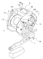
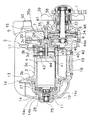
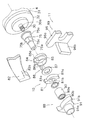
本発明の一実施形態による電動リールは、図1に示すように、主にハンドル1が装着されたリール本体2と、リール本体2に回転自在に装着されたスプール3と、スプール3内に装着されたモータ4とを備えている。リール本体2の上部には、水深表示等を行うためのカウンタ5が装着されている。リール本体2の内部には、図2に示すように、ハンドル1の回転をスプール3に伝達するとともにモータ4の回転をスプール3に伝達する回転伝達機構6と、回転伝達機構6の途中に設けられたクラッチ機構7と、クラッチ機構7を切り換えるクラッチ切換機構8(図4参照)と、ハンドル1の糸繰り出し方向の逆転を禁止する第1ワンウェイクラッチ9と、モータ4の糸繰り出し方向の逆転を禁止する第2ワンウェイクラッチ10と、モータ4の逆転によりクラッチ機構7をクラッチオン状態に戻す第1クラッチ戻し機構11と、ハンドル1の糸巻取方向の回転によりクラッチ機構7をクラッチオン状態に戻す第2クラッチ戻し機構12(図4参照)とを備えている。
〔overall structure〕
As shown in FIG. 1, an electric reel according to an embodiment of the present invention mainly includes a reel body 2 to which a handle 1 is attached, a spool 3 that is rotatably attached to the reel body 2, and an inside of the spool 3. The motor 4 is provided. A counter 5 for displaying a water depth or the like is mounted on the top of the reel body 2. As shown in FIG. 2, a rotation transmission mechanism 6 that transmits the rotation of the handle 1 to the spool 3 and transmits the rotation of the motor 4 to the spool 3 and a rotation transmission mechanism 6 are provided inside the reel body 2. The clutch mechanism 7, the clutch switching mechanism 8 for switching the clutch mechanism 7 (see FIG. 4), the first one-way clutch 9 for prohibiting the reverse rotation of the handle 1 in the thread unwinding direction, and the reverse rotation of the motor 4 in the thread unwinding direction. The second one-way clutch 10 to be prohibited, the first clutch return mechanism 11 that returns the clutch mechanism 7 to the clutch-on state by the reverse rotation of the motor 4, and the first clutch mechanism 7 that returns to the clutch-on state by the rotation of the handle 1 in the yarn winding direction. And a two-clutch return mechanism 12 (see FIG. 4).

〔リール本体の構成〕
リール本体2は、フレーム13と、フレーム13の両側方を覆う第1カバー部材14及び第2カバー部材15とを有している。フレーム13は、アルミニウム合金ダイカストの一体成形された部材であり、左右1対の第1側板16及び第2側板17と、第1側板16及び第2側板17を複数箇所で連結する連結部材18とを有している。下部の連結部材18には、釣竿を装着するための竿装着脚19が装着されている。
[Reel body configuration]
The reel body 2 includes a frame 13 and a first cover member 14 and a second cover member 15 that cover both sides of the frame 13. The frame 13 is an integrally formed member of an aluminum alloy die-cast, and includes a pair of left and right first side plates 16 and second side plates 17, and a connecting member 18 that connects the first side plate 16 and the second side plate 17 at a plurality of locations. have. A rod mounting leg 19 for mounting a fishing rod is mounted on the lower connecting member 18.

第2カバー部材15は、第2側板17にボルトにより締結されている。第2カバー部材15には、回転伝達機構6などを装着するための固定フレーム20がボルトにより締結されている。したがって第2カバー部材15を第2側板17から外すと、固定フレーム20も回転伝達機構6の一部や第2カバー部材15とともに第2側板17から外れる。   The second cover member 15 is fastened to the second side plate 17 with bolts. A fixed frame 20 for mounting the rotation transmission mechanism 6 and the like is fastened to the second cover member 15 with bolts. Therefore, when the second cover member 15 is removed from the second side plate 17, the fixed frame 20 is also detached from the second side plate 17 together with a part of the rotation transmission mechanism 6 and the second cover member 15.

第1カバー部材14は、第1側板16にボルトにより締結されている。第1カバー部材14には、外部に設けられた蓄電池等の電源と接続するための電源ケーブル用のコネクタ部14a(図1参照)が前部に斜めに突出して設けられている。また、第1カバー部材14の中心部には、図2及び図3に示すように、側部を貫通する貫通孔14bが形成されている。   The first cover member 14 is fastened to the first side plate 16 with bolts. The first cover member 14 is provided with a connector portion 14a (see FIG. 1) for a power cable for connecting to a power source such as a storage battery provided outside and projecting obliquely at the front portion. Further, as shown in FIGS. 2 and 3, a through hole 14 b penetrating the side portion is formed in the central portion of the first cover member 14.

第1側板16は、周縁部にリブを有する合成樹脂製の板状部材であり、第1側板16の中心部にはモータ4の端部側を装着するための膨出部27が外方に突出して形成されている。膨出部27の第1カバー部材14側外方には、モータ4の後述する出力軸30の突出部分を覆うための第3カバー部材28が装着されている。   The first side plate 16 is a plate-shaped member made of synthetic resin having a rib on the periphery, and a bulging portion 27 for mounting the end side of the motor 4 is outward in the center of the first side plate 16. Protrusively formed. A third cover member 28 for covering a protruding portion of an output shaft 30 (described later) of the motor 4 is mounted on the outer side of the bulging portion 27 on the first cover member 14 side.

第3カバー部材28は、合成樹脂製のキャップ部材であり、複数のねじ部材14cにより、膨出部27に着脱自在に装着されている。第3カバー部材28は、膨出部27に装着したとき、第1カバー部材14の貫通孔14bを貫通して外方に突出するように形成されている。第3カバー部材28の内部には、出力軸30の突出部分に装着された後述する爪制御機構84やローラクラッチ90や押圧部材91等が配置されている。   The third cover member 28 is a cap member made of synthetic resin, and is detachably attached to the bulging portion 27 by a plurality of screw members 14c. The third cover member 28 is formed so as to penetrate the through hole 14b of the first cover member 14 and protrude outward when mounted on the bulging portion 27. Inside the third cover member 28, a claw control mechanism 84, a roller clutch 90, a pressing member 91, and the like, which will be described later, mounted on the protruding portion of the output shaft 30 are disposed.

〔スプールの構成〕
スプール3は、内部にモータ4を収納可能な筒状の糸巻胴部3aと、糸巻胴部3aの外周部に間隔を隔てて形成された左右1対のフランジ部3bとを有している。スプール3の一端はフランジ部3bから外方に延びており、その延びた端部の内周面に軸受25が配置されている。スプール3の他端には、ギア板3cが固定されている。ギア板3cは、図示しないレベルワインド機構にスプール3の回転を伝達するために設けられている。ギア板3cのスプール中心側部において、ギア板3cと固定フレーム20との間には転がり軸受26が装着されている。この2つの軸受25、26により、スプール3は、リール本体2に回転自在に支持されている。
[Spool configuration]
The spool 3 includes a cylindrical bobbin trunk 3a capable of accommodating the motor 4 therein, and a pair of left and right flanges 3b formed on the outer periphery of the bobbin trunk 3a with a space therebetween. One end of the spool 3 extends outward from the flange portion 3b, and a bearing 25 is disposed on the inner peripheral surface of the extended end portion. A gear plate 3 c is fixed to the other end of the spool 3. The gear plate 3c is provided to transmit the rotation of the spool 3 to a level wind mechanism (not shown). A rolling bearing 26 is mounted between the gear plate 3c and the fixed frame 20 on the spool center side portion of the gear plate 3c. The spool 3 is rotatably supported by the reel body 2 by the two bearings 25 and 26.

〔モータの構成〕
モータ4は、内部に界磁や電機子を有する直流モータであり、スプール3の糸巻き取り用、糸繰り出し用及び第1クラッチ戻し機構11の動作用のアクチュエータとして機能する。モータ4は、基端が開口する有底筒状のケース部材31と、開口を塞ぐためにケース部材31の基端に固定されたキャップ部材32と、ケース部材31とキャップ部材32とに回転自在に装着された出力軸30とを有している。ケース部材31は、有底筒状の部材であり、底部で出力軸30を回転自在に支持している。
[Motor configuration]
The motor 4 is a direct current motor having a field and an armature therein, and functions as an actuator for winding the spool 3, winding the yarn, and operating the first clutch return mechanism 11. The motor 4 is rotatable to a bottomed cylindrical case member 31 whose base end is open, a cap member 32 fixed to the base end of the case member 31 to close the opening, and the case member 31 and the cap member 32. And an attached output shaft 30. The case member 31 is a bottomed cylindrical member, and rotatably supports the output shaft 30 at the bottom.

出力軸30は、ケース部材31とキャップ部材32とに回転自在に装着された軸本体30aと、軸本体の左端に回転不能に装着された機構装着軸75とを有している。軸本体30aの右端は、図3に示すようにケース部材31の先端から突出している。この突出した先端には、回転伝達機構6を構成する2段減速の遊星歯車機構40が装着されている。また、左端は、キャップ部材32から突出しており、そこには、機構装着軸75が回転不能に装着されている。機構装着軸75は、図7に示すように、基端側に断面が円形に形成された大径の第1軸部75aと、互いに平行な面取り部75cが形成され第1軸部75aより小径の第2軸部75bと、断面が円形に形成され第2軸部75bより小径の第3軸部75dとを有している。   The output shaft 30 includes a shaft main body 30a rotatably mounted on the case member 31 and the cap member 32, and a mechanism mounting shaft 75 mounted non-rotatably on the left end of the shaft main body. The right end of the shaft body 30a protrudes from the tip of the case member 31 as shown in FIG. A two-stage reduction planetary gear mechanism 40 constituting the rotation transmission mechanism 6 is attached to the protruding tip. Further, the left end protrudes from the cap member 32, and the mechanism mounting shaft 75 is mounted on the left end so as not to rotate. As shown in FIG. 7, the mechanism mounting shaft 75 has a large-diameter first shaft portion 75a having a circular cross section on the base end side, and a chamfered portion 75c parallel to each other, and a smaller diameter than the first shaft portion 75a. The second shaft portion 75b and a third shaft portion 75d having a circular cross section and a smaller diameter than the second shaft portion 75b.

〔カウンタの構成〕
カウンタ5は、釣り糸の先端に装着された仕掛けの水深を表示するとともに、モータ4を制御するために設けられている。カウンタ5には、仕掛けの水深や棚位置を水面からと底からとの2つの基準で表示するための液晶表示ディスプレイからなる水深表示部98と、水深表示部98の周囲に配置された複数のスイッチからなるスイッチ操作部99とが設けられている。
[Counter configuration]
The counter 5 is provided for controlling the motor 4 while displaying the water depth of the device attached to the tip of the fishing line. The counter 5 includes a water depth display unit 98 composed of a liquid crystal display for displaying the water depth and shelf position of the device on the basis of two criteria, from the water surface and from the bottom, and a plurality of water depth display units 98 arranged around the water depth display unit 98. A switch operation unit 99 including a switch is provided.

スイッチ操作部99は、図11に示すように、水深表示部98の右側に上下に配置されたモータオン、オフ用のパワースイッチPWと、釣り糸に関するモードを設定するための釣りモード設定スイッチLFと、左側に上下に並べて配置されたさそいスイッチIBと、糸長と水深との関係に関する設定を行う水深設定モードスイッチMDと、棚位置や底位置を設定するための位置設定スイッチMSとを有している。   As shown in FIG. 11, the switch operating unit 99 includes a motor on / off power switch PW arranged vertically on the right side of the water depth display unit 98, a fishing mode setting switch LF for setting a mode related to fishing line, There is a saddle switch IB arranged vertically on the left side, a water depth setting mode switch MD for setting the relationship between the yarn length and the water depth, and a position setting switch MS for setting the shelf position and the bottom position. Yes.

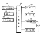
また、カウンタ5の内部には、図12に示すように、水深表示部98やモータ4を制御するためのマイクロコンピュータからなるリール制御部100が設けられている。リール制御部100には、スイッチ操作部99と、スプールの速度や釣り糸の張力を調整するための調整レバー101と、スプール3の回転数と回転方向とを、たとえば回転方向に並べて配置された2つのリードスイッチで検出するスプールセンサ102と、各種の報知用のブザー103と、水深表示部98と、モータ4をPWM(パルス幅変調)駆動するモータ駆動回路105と、他の入出力部利賀接続されている。リール制御部100は、調整レバー101の操作量に応じてモータ4の速度やトルクを制御する。また、スプールセンサ102の出力により釣り糸の先端に取り付けられる仕掛けの水深を算出し、それを水深表示部98に表示する。さらに、スイッチ操作部99の操作により底位置や棚位置が設定されると、算出された水深と設定された底位置や棚位置とが一致して仕掛け棚位置や底位置に到達したときに、モータ4を逆転させて第1クラッチ戻し機構12を介してクラッチ切換機構8を動作させクラッチ機構7をクラッチオン状態に戻す。これにより、仕掛けがその位置に配置される。   Further, as shown in FIG. 12, a reel control unit 100 including a water depth display unit 98 and a microcomputer for controlling the motor 4 is provided inside the counter 5. In the reel control unit 100, a switch operation unit 99, an adjustment lever 101 for adjusting the speed of the spool and the tension of the fishing line, and the number of rotations and the rotation direction of the spool 3 are arranged in, for example, the rotation direction. Spool sensor 102 detected by one reed switch, various notification buzzers 103, water depth display unit 98, motor drive circuit 105 for driving the motor 4 by PWM (pulse width modulation), and other input / output unit Toga connection Has been. The reel control unit 100 controls the speed and torque of the motor 4 according to the operation amount of the adjustment lever 101. Further, the water depth of the device attached to the tip of the fishing line is calculated from the output of the spool sensor 102 and displayed on the water depth display unit 98. Further, when the bottom position and the shelf position are set by the operation of the switch operation unit 99, when the calculated water depth matches the set bottom position and the shelf position and reaches the device shelf position and the bottom position, The motor 4 is reversely rotated to operate the clutch switching mechanism 8 via the first clutch return mechanism 12 to return the clutch mechanism 7 to the clutch-on state. Thereby, the device is arranged at that position.

〔回転伝達機構の構成〕
回転伝達機構6は、ハンドル1が回転不能に装着されたハンドル軸33と、ハンドル軸に回転自在に装着されたメインギア34と、メインギアに噛み合うピニオンギア35と、ハンドル軸33の周囲に配置されたドラグ機構36と、モータ4の回転を2段階で減速する遊星歯車機構40とを有している。
[Configuration of rotation transmission mechanism]
The rotation transmission mechanism 6 is disposed around the handle shaft 33, the handle shaft 33 on which the handle 1 is non-rotatably mounted, the main gear 34 rotatably mounted on the handle shaft, the pinion gear 35 meshing with the main gear, and the handle shaft 33. The drag mechanism 36 and a planetary gear mechanism 40 that decelerates the rotation of the motor 4 in two stages.

ハンドル軸33は、固定フレーム20に軸受37とハンドル軸33の糸繰り出し方向の回転を禁止するローラクラッチ38とにより回転自在に支持されている。ハンドル軸33の先端にハンドル1が回転不能に装着され、その内側にドラグ機構36のスタードラグ39が螺合している。   The handle shaft 33 is rotatably supported on the fixed frame 20 by a bearing 37 and a roller clutch 38 that prohibits rotation of the handle shaft 33 in the thread drawing direction. The handle 1 is non-rotatably attached to the tip of the handle shaft 33, and the star drag 39 of the drag mechanism 36 is screwed inside.

メインギア34には、ドラグ機構36を介してハンドル軸33の回転が伝達される。ピニオンギア35は、第2カバー部材15に立設されたピニオンギア軸47に回転自在かつ軸方向移動自在に装着されている。ピニオンギア軸47は、モータ4の出力軸30と同芯に配置されている。ピニオンギア35の図2左端には、係合凹部35aが形成され、右端にはメインギア34に噛み合う歯部35bが形成されている。またその間には小径のくびれ部35cが形成されている。係合凹部35aは、遊星歯車機構40の後述する第2キャリア46の先端(図2右端)に形成された係合凸部46aに回転不能に係合する。クラッチ機構7は、この係合凹部35aと、係合凸部46aとにより構成されている。ピニオンギア35は、くびれ部35cに係合するクラッチ切換機構8によりピニオンギア軸47の軸方向に移動する。   The rotation of the handle shaft 33 is transmitted to the main gear 34 via the drag mechanism 36. The pinion gear 35 is attached to a pinion gear shaft 47 erected on the second cover member 15 so as to be rotatable and axially movable. The pinion gear shaft 47 is disposed concentrically with the output shaft 30 of the motor 4. An engagement recess 35 a is formed at the left end of the pinion gear 35 in FIG. 2, and a tooth portion 35 b that meshes with the main gear 34 is formed at the right end. A small-diameter constricted portion 35c is formed between them. The engagement recess 35a engages with an engagement protrusion 46a formed at the tip (right end in FIG. 2) of the planetary gear mechanism 40, which will be described later, in a non-rotatable manner. The clutch mechanism 7 is composed of the engagement concave portion 35a and the engagement convex portion 46a. The pinion gear 35 is moved in the axial direction of the pinion gear shaft 47 by the clutch switching mechanism 8 engaged with the constricted portion 35c.

ドラグ機構36は、スプール3の糸繰り出し方向の回転を制動するものであり、スタードラグ39と、スタードラグ39によりメインギア34に対する押圧力(ドラグ力)が変化するドラグディスク48とを有する公知の機構である。   The drag mechanism 36 brakes the rotation of the spool 3 in the yarn unwinding direction. The drag mechanism 36 includes a star drag 39 and a drag disk 48 in which a pressing force (drag force) on the main gear 34 is changed by the star drag 39. Mechanism.

遊星歯車機構40は、図3に示すように、モータ4の図3右側の出力軸30に固定された第1太陽ギア41と、第1太陽ギア41に噛み合う、たとえば円周上に等間隔で配置された3つの第1遊星ギア43と、第1遊星ギア43を回転自在に支持する第1キャリア45と、第1キャリア45に固定された第2太陽ギア42と、第2太陽ギア42に噛み合うたとえば円周上に等間隔で配置された3つの第2遊星ギア44と、第2遊星ギア44を回転自在に支持する第2キャリア46とを備えている。第1遊星ギア43及び第2遊星ギア44は、スプール3の内周面に形成された内歯ギア3dに噛み合っている。第1キャリア45及び第2キャリア46は筒状軸となっており、内部をモータ4の出力軸30が貫通している。第2太陽ギア42及び第2キャリア46は出力軸30に対して相対回転可能に設けられている。また、第2キャリア46は、ギア板3cに回転自在に装着されている。第2遊星ギア44と、第1キャリア45との間には、滑りやすい性質の合成樹脂製のワッシャ部材29が装着されている。このようなワッシャ部材29を装着すると、第1キャリア45の遊びが減少して遊星歯車機構40の騒音の低下を図ることができる。   As shown in FIG. 3, the planetary gear mechanism 40 is engaged with the first sun gear 41 fixed to the output shaft 30 on the right side of FIG. 3 of the motor 4 and the first sun gear 41, for example, at equal intervals on the circumference. Three first planetary gears 43 arranged, a first carrier 45 rotatably supporting the first planetary gear 43, a second sun gear 42 fixed to the first carrier 45, and a second sun gear 42 For example, it includes three second planetary gears 44 that are arranged at regular intervals on the circumference, for example, and a second carrier 46 that rotatably supports the second planetary gear 44. The first planetary gear 43 and the second planetary gear 44 mesh with an internal gear 3 d formed on the inner peripheral surface of the spool 3. The first carrier 45 and the second carrier 46 are cylindrical shafts, through which the output shaft 30 of the motor 4 passes. The second sun gear 42 and the second carrier 46 are provided to be rotatable relative to the output shaft 30. The second carrier 46 is rotatably mounted on the gear plate 3c. Between the second planetary gear 44 and the first carrier 45, a washer member 29 made of synthetic resin having a slippery property is mounted. When such a washer member 29 is mounted, the play of the first carrier 45 is reduced, and the noise of the planetary gear mechanism 40 can be reduced.

〔クラッチ機構の構成〕
クラッチ機構7は、スプール3を糸巻取可能状態と自由回転可能状態とに切換可能な機構である。クラッチ機構7は、図2に示すように、前述したようにピニオンギア35の係合凹部35aと第2キャリア46の係合凸部46aと構成されている。ピニオンギア35が、左方に移動して係合凹部35aと第2キャリア46の係合凸部46aと係合した状態がクラッチオン状態でなり、離反した状態がクラッチオフ状態である。クラッチオン状態では、スプール3は糸巻取可能状態になり、クラッチオン状態では、スプール3は自由回転可能状態になる。なお、クラッチオフ状態でモータ4を糸巻取方向に回すと遊星歯車機構40の摩擦抵抗が小さくなる。この結果、スプール3の自由回転速度が増加し、仕掛けを素早く棚位置に下ろすことができる。これが糸送り処理である。
[Configuration of clutch mechanism]
The clutch mechanism 7 is a mechanism capable of switching the spool 3 between a yarn winding-capable state and a free-rotatable state. As shown in FIG. 2, the clutch mechanism 7 is configured by the engagement concave portion 35 a of the pinion gear 35 and the engagement convex portion 46 a of the second carrier 46 as described above. The state in which the pinion gear 35 moves to the left and engages with the engagement recess 35a and the engagement protrusion 46a of the second carrier 46 is the clutch-on state, and the separated state is the clutch-off state. In the clutch-on state, the spool 3 is in a yarn winding-capable state, and in the clutch-on state, the spool 3 is in a freely rotatable state. If the motor 4 is turned in the yarn winding direction in the clutch-off state, the frictional resistance of the planetary gear mechanism 40 is reduced. As a result, the free rotation speed of the spool 3 increases, and the device can be quickly lowered to the shelf position. This is the yarn feeding process.

〔クラッチ切換機構の構成〕
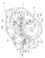
クラッチ切換機構8は、クラッチ機構7のオン、オフ状態を切り換えるものである。クラッチ切換機構8は、図4及び図5に示すように、第2カバー部材15に揺動自在に装着されたクラッチ操作レバー50と、クラッチ操作レバー50の揺動によりピニオンギア軸47回りに回動するクラッチカム51と、クラッチカム51の回動によりピニオンギア軸47方向に移動するクラッチヨーク52とを有している。
[Configuration of clutch switching mechanism]
The clutch switching mechanism 8 switches the on / off state of the clutch mechanism 7. As shown in FIGS. 4 and 5, the clutch switching mechanism 8 includes a clutch operating lever 50 that is swingably attached to the second cover member 15, and rotates around the pinion gear shaft 47 by the swinging of the clutch operating lever 50. A clutch cam 51 that moves, and a clutch yoke 52 that moves in the direction of the pinion gear shaft 47 as the clutch cam 51 rotates are provided.

クラッチ操作レバー50は、図4及び図5に示すように、スプール3の後方かつ上方で第2カバー部材15に揺動自在に装着されている。クラッチ操作レバー50は、図4に示すクラッチオン位置と図5に示すクラッチオフ位置との間で揺動自在である。   As shown in FIGS. 4 and 5, the clutch operating lever 50 is swingably attached to the second cover member 15 behind and above the spool 3. The clutch operation lever 50 can swing between a clutch-on position shown in FIG. 4 and a clutch-off position shown in FIG.

クラッチカム51は、クラッチ操作レバー50の揺動によりピニオンギア軸47回りに回動する部材であり、回動によりクラッチヨーク52をスプール軸外方に移動させるものである。クラッチカム51は、ピニオンギア軸47回りに回動自在に装着された回動部55と、回動部55からクラッチ操作レバー50側に延びる第1突出部56aと、回動部55から前方に延びる第2突出部56bと、回動部55から後方に延びる第3突出部56cと、回動部55の側面に形成された傾斜カムからなる1対のカム突起57a、57bとを有している。このカム突起57a、57bに対向するクラッチヨーク52の両端には、カム突起57a、57bに乗り上げる図示しないカム受けが形成されている。   The clutch cam 51 is a member that rotates around the pinion gear shaft 47 when the clutch operation lever 50 swings, and moves the clutch yoke 52 outward of the spool shaft by rotation. The clutch cam 51 includes a rotating portion 55 that is rotatably mounted around the pinion gear shaft 47, a first projecting portion 56a that extends from the rotating portion 55 toward the clutch operation lever 50, and a front side from the rotating portion 55. It has a second projecting portion 56 b that extends, a third projecting portion 56 c that extends rearward from the rotating portion 55, and a pair of cam protrusions 57 a and 57 b that are formed of inclined cams formed on the side surfaces of the rotating portion 55. Yes. At both ends of the clutch yoke 52 facing the cam protrusions 57a and 57b, cam receivers (not shown) that ride on the cam protrusions 57a and 57b are formed.

回動部55は、リング状に形成されており、クラッチヨーク52と固定フレーム20との間に配置されている。回動部55は、固定フレーム20に回動自在に支持されている。   The rotating portion 55 is formed in a ring shape and is disposed between the clutch yoke 52 and the fixed frame 20. The rotating part 55 is rotatably supported by the fixed frame 20.

第1突出部56aは、回動部55から上後方に延び、先端は二股に分かれてクラッチ操作レバー50に係合している。この第1突出部56aは、クラッチ操作レバー50の揺動に応じてクラッチカム51を回動させるために設けられている。   The first projecting portion 56 a extends upward and rearward from the rotating portion 55, and the tip is divided into two portions and is engaged with the clutch operation lever 50. The first protrusion 56 a is provided to rotate the clutch cam 51 in response to the swing of the clutch operation lever 50.

第2突出部56bは、クラッチ切換機構8を第2クラッチ戻し機構12に連動させるために設けられている。第2突出部56bは、リールの前方に延びており、メインギア34と固定フレーム20との間に配置された第1ワンウェイクラッチ9のラチェットホイール62の外方側に延びている。第2突出部56bには、捩じりコイルばねからなる第1トグルばね65が係止されている。第1トグルばね65の他端は固定フレーム20に係止されている。この第1トグルばね65により、クラッチカム51は、図4に示すクラッチオン位置と、図5に示すクラッチオフ位置とに保持される。また、第2突出部56bには、揺動軸51aが装着されており、この揺動軸51aに第2クラッチ戻し機構12の係合部材61が揺動自在に装着されている。   The second projecting portion 56 b is provided for interlocking the clutch switching mechanism 8 with the second clutch return mechanism 12. The second projecting portion 56b extends forward of the reel, and extends outward of the ratchet wheel 62 of the first one-way clutch 9 disposed between the main gear 34 and the fixed frame 20. A first toggle spring 65 made of a torsion coil spring is engaged with the second protrusion 56b. The other end of the first toggle spring 65 is locked to the fixed frame 20. By the first toggle spring 65, the clutch cam 51 is held at the clutch-on position shown in FIG. 4 and the clutch-off position shown in FIG. A swing shaft 51a is mounted on the second protrusion 56b, and an engagement member 61 of the second clutch return mechanism 12 is swingably mounted on the swing shaft 51a.

第3突出部56cは、クラッチ切換機構8を第1クラッチ戻し機構11に連動させるために設けられている。第3突出部56cは、リールの後下方に延びており、その先端に第1クラッチ戻し機構11が連結されている。   The third projecting portion 56 c is provided for interlocking the clutch switching mechanism 8 with the first clutch return mechanism 11. The third protrusion 56c extends rearward and downward of the reel, and the first clutch return mechanism 11 is connected to the tip of the third protrusion 56c.

カム突起57a、57bは、クラッチヨーク52をスプール軸方向外方に押圧するために設けられている。すなわち、クラッチカム51が図4に示すクラッチオン位置から図5に示すクラッチオフ位置に回動すると、カム突起57a、57bにクラッチヨーク52が乗り上げてスプール軸方向外方(図4、図5紙面手前方向)に移動する。   The cam protrusions 57a and 57b are provided to press the clutch yoke 52 outward in the spool axial direction. That is, when the clutch cam 51 rotates from the clutch-on position shown in FIG. 4 to the clutch-off position shown in FIG. 5, the clutch yoke 52 rides on the cam protrusions 57a and 57b and moves outward in the spool axial direction (see FIG. 4 and FIG. 5). Move forward).

クラッチヨーク52は、ピニオンギア軸47の外周側に配置されており、2本のガイド軸53によってピニオンギア軸47の軸心と平行に移動可能に支持されている。また、クラッチヨーク52はその中央部にピニオンギア35のくびれ部35cに係合する半円弧状の係合部52aを有している。また、クラッチヨーク52を支持するガイド軸53の外周でクラッチヨーク52と第2カバー部材15との間にはコイルばね54が圧縮状態で配置されており、クラッチヨーク52はコイルばね54によって常に内方(第2側板17側)に付勢されている。   The clutch yoke 52 is disposed on the outer peripheral side of the pinion gear shaft 47, and is supported by two guide shafts 53 so as to be movable in parallel with the axis of the pinion gear shaft 47. The clutch yoke 52 has a semicircular arc engaging portion 52a that engages with the constricted portion 35c of the pinion gear 35 at the center thereof. In addition, a coil spring 54 is disposed in a compressed state between the clutch yoke 52 and the second cover member 15 on the outer periphery of the guide shaft 53 that supports the clutch yoke 52. (Second side plate 17 side) is biased.

このような構成では、通常状態ではピニオンギア35は内方のクラッチ係合位置に位置しており、その係合凹部35aと第2キャリア46の係合凸部46aとが係合してクラッチ機構7がクラッチオン状態となっている。一方、クラッチヨーク52によってピニオンギア35が外方に移動した場合は、係合凹部35aと係合凸部46aとの係合が外れ、クラッチオフ状態となる。   In such a configuration, in a normal state, the pinion gear 35 is located at the inner clutch engagement position, and the engagement concave portion 35a and the engagement convex portion 46a of the second carrier 46 are engaged with each other to provide a clutch mechanism. 7 is in a clutch-on state. On the other hand, when the pinion gear 35 is moved outward by the clutch yoke 52, the engagement concave portion 35a and the engagement convex portion 46a are disengaged, and the clutch is turned off.

〔第1ワンウェイクラッチの構成〕
第1ワンウェイクラッチ9は、ハンドル軸33の糸繰り出し方向の回転を禁止することにより、モータ4駆動時にハンドル1が回転するのを防止するために設けられている。第1ワンウェイクラッチ9は、ハンドル軸33に回転不能に装着されたラチェットホイール62と、ラチェットホイール62と、ラチェット爪71と、挟持部材72とを有している。
[Configuration of the first one-way clutch]
The first one-way clutch 9 is provided to prevent the handle 1 from rotating when the motor 4 is driven, by prohibiting the handle shaft 33 from rotating in the yarn drawing direction. The first one-way clutch 9 includes a ratchet wheel 62 that is non-rotatably attached to the handle shaft 33, a ratchet wheel 62, a ratchet pawl 71, and a clamping member 72.

ラチェットホイール62はメインギア34と固定フレーム20との間でハンドル軸33に回転不能に装着されている。ラチェットホイール62の外周側には鋸歯状のラチェット歯62aが形成されている。   The ratchet wheel 62 is non-rotatably mounted on the handle shaft 33 between the main gear 34 and the fixed frame 20. On the outer peripheral side of the ratchet wheel 62, serrated ratchet teeth 62a are formed.

ラチェット爪71は第2側板17に回動自在に装着されている。また挟持部材72はラチェット爪71の先端に取り付けられ、ラチェットホイール62の外周面を挟持可能である。この挟持部材72とラチェットホイール62との摩擦によって、ラチェットホイール62の時計回り(糸巻取方向)の回転時にはラチェット爪71がラチェット歯62aと干渉しない位置まで離れられ、ラチェットホイール62の糸巻取方向の回転時にラチェット爪71が接触しなくなり静音化できる。一方、反時計回り(糸繰り出し方向)の回転時にはラチェット爪71がラチェット歯62aと干渉する位置まで引き込まれ、糸繰り出し方向の回転が禁止される。なお、この電動リールには、このような第1ワンウェイクラッチ9に加えて、ハンドル軸33の逆転を瞬時に禁止するローラクラッチ38が第2カバー部材15とハンドル軸33との間に配置されている。   The ratchet pawl 71 is rotatably mounted on the second side plate 17. The clamping member 72 is attached to the tip of the ratchet pawl 71 and can clamp the outer peripheral surface of the ratchet wheel 62. Due to the friction between the pinching member 72 and the ratchet wheel 62, the ratchet pawl 71 is separated to a position where it does not interfere with the ratchet teeth 62a when the ratchet wheel 62 rotates clockwise (yarn winding direction). The ratchet pawl 71 does not come into contact with each other at the time of rotation, and the noise can be reduced. On the other hand, when rotating counterclockwise (yarn feeding direction), the ratchet pawl 71 is pulled to a position where it interferes with the ratchet teeth 62a, and rotation in the yarn drawing direction is prohibited. In this electric reel, in addition to the first one-way clutch 9, a roller clutch 38 that instantaneously inhibits the reverse rotation of the handle shaft 33 is disposed between the second cover member 15 and the handle shaft 33. Yes.

〔第2ワンウェイクラッチの構成〕
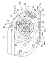
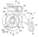
第2ワンウェイクラッチ10は、ハンドル1の操作時にモータ4が逆転することにより遊星歯車機構40が動作するのを防止するために設けられている。第2ワンウェイクラッチ10は、図6及び図7に示すように、機構装着軸75の第2軸部75bに回転不能に装着された爪車81と、爪車81に対して接離する揺動爪82と、揺動爪82を爪車に向けて付勢する捩じりコイルばね83と、モータ4の糸巻取方向の正転時に揺動爪82を制御する爪制御機構84とを有している。
[Configuration of the second one-way clutch]
The second one-way clutch 10 is provided to prevent the planetary gear mechanism 40 from operating due to the reverse rotation of the motor 4 when the handle 1 is operated. As shown in FIGS. 6 and 7, the second one-way clutch 10 is a claw wheel 81 that is non-rotatably mounted on the second shaft portion 75 b of the mechanism mounting shaft 75, and a swing that makes contact with and separates from the claw wheel 81. A claw 82; a torsion coil spring 83 that urges the swing claw 82 toward the claw wheel; and a claw control mechanism 84 that controls the swing claw 82 when the motor 4 rotates forward in the yarn winding direction. ing.

爪車81は、中心に機構装着軸75の第2軸部75bに形成された面取り部75cに回転不能に係合する小判孔81bを有している。また、外周に径方向に突出して形成されたたとえば2つの突起部81aを有している。   The claw wheel 81 has an oval hole 81b that engages with a chamfered portion 75c formed in the second shaft portion 75b of the mechanism mounting shaft 75 in a non-rotatable manner at the center. Moreover, it has two protrusion parts 81a formed in the outer periphery so as to protrude in the radial direction.

揺動爪82は、第1側板16の膨出部27に立設された揺動軸80に揺動自在に基端が装着されている。揺動爪82の先端には、図7奥側に突出する爪部82aが形成されている。爪部82aは、爪車81の突起部81aに接触して爪車81(出力軸30)の逆転を阻止するとともに、爪制御機構84の後述する静音カム85に接触して突起部81aをかわす位置まで揺動爪82を揺動させるために設けられている。   The swinging claw 82 has a proximal end mounted on a swinging shaft 80 erected on the bulging portion 27 of the first side plate 16 so as to be swingable. At the tip of the swinging claw 82, a claw portion 82a that protrudes toward the back side in FIG. 7 is formed. The claw portion 82a contacts the projection 81a of the claw wheel 81 to prevent reverse rotation of the claw wheel 81 (output shaft 30), and contacts the silent cam 85 (to be described later) of the claw control mechanism 84 to dodge the projection 81a. It is provided to swing the swinging claw 82 to the position.

揺動爪82は、第1クラッチ戻し機構11により、図8に示す突起部81aに接触可能な逆転禁止位置と、図9に示す逆転許可位置との間で揺動するとともに、図10に示すように、モータ4の正転時に爪車81の突起部81aをかわす位置まで僅かに逆転許可位置側に揺動する。   The swinging claw 82 swings between the reverse rotation prohibiting position where the first clutch return mechanism 11 can contact the protrusion 81a shown in FIG. 8 and the reverse rotation permission position shown in FIG. As described above, when the motor 4 is rotating forward, it swings slightly toward the reverse rotation permission position to the position where the projection 81a of the ratchet wheel 81 is dodged.

爪制御機構84は、モータ4が正転すると爪車81の突起部81aをかわす位置まで揺動爪82を逆転許可位置側に揺動させるための機構である。爪制御機構84は、機構装着軸75の第1軸部75aに回転自在に装着され、外周に揺動爪82を逆転禁止位置側に押圧するための突出した押圧部85aを有する静音カム85と、静音カム85の回動範囲を規制する回動規制部86とを有している。静音カム85は、第1軸部75aに摩擦係合しており、機構装着軸75の回動に連動して同じ方向に回動するとともに、回動規制部86によって静音カム85の回動が規制されても機構装着軸75は回転できるようになっている。回動規制部86は、静音カム85に径方向に突出して一体形成された係止片86aと、第3カバー部材28に形成され係止片86aが係止される切欠き部86bとを有している。切欠き部86bは、第3カバー部材28の円弧状の側面を揺動範囲だけ円弧状に切り欠いて形成れている。静音カム85と爪車81との間には、ワッシャ87が装着されている。 The claw control mechanism 84 is a mechanism for swinging the swing claw 82 to the reverse rotation permission position side to a position where the projection 81a of the claw wheel 81 is displaced when the motor 4 rotates forward. The claw control mechanism 84 is rotatably mounted on the first shaft portion 75a of the mechanism mounting shaft 75, and has a silent cam 85 having a protruding pressing portion 85a on the outer periphery for pressing the swinging claw 82 toward the reverse rotation prohibiting position. And a rotation restricting portion 86 for restricting the rotation range of the silent cam 85. The silent cam 85 is frictionally engaged with the first shaft portion 75 a and rotates in the same direction in conjunction with the rotation of the mechanism mounting shaft 75, and the rotation cam 86 rotates the silent cam 85. The mechanism mounting shaft 75 can rotate even if it is restricted. The rotation restricting portion 86 has a locking piece 86a that is integrally formed so as to protrude in the radial direction from the silent cam 85, and a notch portion 86b that is formed on the third cover member 28 and is locked with the locking piece 86a. is doing. The notch 86b is formed by notching the arc-shaped side surface of the third cover member 28 in an arc shape within the swing range. A washer 87 is mounted between the silent cam 85 and the claw wheel 81.

〔第1クラッチ戻し機構の構成〕
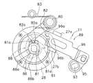
第1クラッチ戻し機構11は、モータ4の逆転によりクラッチ切換機構8を介してクラッチ機構7をクラッチオフ状態からクラッチオン状態に戻すものである。第1クラッチ戻し機構11は、図4〜図7に示すように、爪車81と並べて機構装着軸75に装着され少なくともモータ4の逆転に連動して回転する押圧機構88と、クラッチ切換機構8と連動して動作する連動機構89とを有している。
[Configuration of first clutch return mechanism]
The first clutch return mechanism 11 returns the clutch mechanism 7 from the clutch-off state to the clutch-on state via the clutch switching mechanism 8 by the reverse rotation of the motor 4. As shown in FIGS. 4 to 7, the first clutch return mechanism 11 includes a pressing mechanism 88 that is mounted on the mechanism mounting shaft 75 side by side with the ratchet wheel 81 and rotates in conjunction with at least the reverse rotation of the motor 4, and the clutch switching mechanism 8. And an interlocking mechanism 89 that operates in conjunction with the.

押圧機構88は、爪車81と並べて機構装着軸75の第3軸部75dに配置され、モータ4の逆転に連動して回転するものである。押圧機構88は、第3軸部75dに装着されたローラクラッチ90と、ローラクラッチ90の外周側に回転不能に装着された押圧部材91とを有している。ローラクラッチ90は、外輪90aと、外輪90aに収納された複数のローラ90bとを有する外輪遊転型のワンウェイクラッチである。なお、内輪は機構装着軸75の第3軸部75dと一体化されている。ローラクラッチ90は、モータ4の逆転のみ押圧部材に伝達するものである。ここで、押圧部材91にローラクラッチ90を装着したのは、クラッチオフ状態で連動機構89が押圧部材91に近接しモータ4を正転させる糸送りモードのとき、押圧部材91が連動機構89に接触しても問題が生じないようにするためである。押圧部材91は、モータ4が逆転するとその回転がローラクラッチ90を介して伝達されて回転する。押圧部材91は、ローラクラッチ90の外輪90aに回転不能に装着される筒状部91aと、筒状部91aの外周側に径方向に突出し周方向に間隔を隔てて形成された、たとえば3つの突起部91bとを有している。突起部91bは、連動機構89を押圧可能な突起である。   The pressing mechanism 88 is arranged on the third shaft portion 75 d of the mechanism mounting shaft 75 side by side with the claw wheel 81, and rotates in conjunction with the reverse rotation of the motor 4. The pressing mechanism 88 includes a roller clutch 90 mounted on the third shaft portion 75d and a pressing member 91 mounted non-rotatably on the outer peripheral side of the roller clutch 90. The roller clutch 90 is an outer ring idle type one-way clutch having an outer ring 90a and a plurality of rollers 90b housed in the outer ring 90a. The inner ring is integrated with the third shaft portion 75d of the mechanism mounting shaft 75. The roller clutch 90 transmits only the reverse rotation of the motor 4 to the pressing member. Here, the roller clutch 90 is attached to the pressing member 91 when the interlocking mechanism 89 is close to the pressing member 91 and the motor 4 is rotated forward in the clutch-off state. This is to prevent a problem from occurring even if contact is made. When the motor 4 rotates in the reverse direction, the rotation of the pressing member 91 is transmitted via the roller clutch 90 and rotates. The pressing member 91 includes, for example, three cylindrical portions 91a that are non-rotatably mounted on the outer ring 90a of the roller clutch 90, and are formed on the outer peripheral side of the cylindrical portion 91a in the radial direction and spaced apart in the circumferential direction. And a protrusion 91b. The protrusion 91 b is a protrusion that can press the interlock mechanism 89.

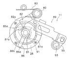
連動機構89は、クラッチ切換機構8の動作に連動して動作し、クラッチ切換機構8によりクラッチ機構7がクラッチオフ状態に切り換えられると、揺動爪82に接触して揺動爪82を爪車81から離反させるとともに押圧機構88による押圧が可能な解放位置に移動する。これにより、モータ4が逆転許可状態になる。また、連動機構89は、その状態でモータ4が逆転すると押圧機構88により押圧されて押圧が不能な係止位置に移動する。係止位置に移動すると揺動爪82から離反して揺動爪82が爪車81に係止する。   The interlocking mechanism 89 operates in conjunction with the operation of the clutch switching mechanism 8. When the clutch mechanism 7 is switched to the clutch-off state by the clutch switching mechanism 8, the interlocking mechanism 89 comes into contact with the swinging claw 82 and moves the swinging claw 82 to the claw wheel. It moves away from 81 and moves to a release position where pressing by the pressing mechanism 88 is possible. As a result, the motor 4 enters the reverse rotation permission state. Further, when the motor 4 rotates in the reverse state, the interlocking mechanism 89 is pressed by the pressing mechanism 88 and moves to a locking position where pressing is impossible. When moved to the locking position, the swinging claw 82 moves away from the swinging claw 82 and is locked to the claw wheel 81.

連動機構89は、第1側板16及び第2側板17を貫通して第1側板16及び第2側板17に回転自在に装着された一端が固定フレーム20の外方に配置される連結軸93と、連結軸93の両端に回転不能に装着された第1及び第2レバー部材94、95と、第2レバー部材95の先端に連結された進退部材96とを有している。   The interlocking mechanism 89 includes a connecting shaft 93 that passes through the first side plate 16 and the second side plate 17 and is rotatably mounted on the first side plate 16 and the second side plate 17. The first and second lever members 94 and 95 are rotatably attached to both ends of the connecting shaft 93, and the advance / retreat member 96 is connected to the tip of the second lever member 95.

連結軸93は、第1側板16及び第2側板17に回転自在に装着され、一端が固定フレーム20の外方に突出し他端が第1側板16の外方に突出する軸部材である。連結軸93の突出した両端には、第1及び第2レバー部材94、95を回転不能に装着するための互いに平行な面取り部93a、93bが形成されている
第1レバー部材94は、基端が連結軸93の固定フレーム20側の面取り部93aに回転不能に装着された部材である。第1レバー部材94の先端は、クラッチ切換機構8を構成するクラッチカム51の第3突出部56cの先端に回動自在かつ所定距離移動自在に係止されている。これにより、クラッチカム51の回動が第1クラッチ戻し機構11に伝達されるとともに、第1クラッチ戻し機構11の戻し動作がクラッチカム51に伝達されクラッチ切換機構8を動作させることができる。
The connecting shaft 93 is a shaft member that is rotatably attached to the first side plate 16 and the second side plate 17 and has one end protruding outward of the fixed frame 20 and the other end protruding outward of the first side plate 16. The projecting ends of the connecting shaft 93 are formed with chamfered portions 93a and 93b parallel to each other for mounting the first and second lever members 94 and 95 in a non-rotatable manner. Is a member that is non-rotatably attached to the chamfered portion 93a of the connecting shaft 93 on the fixed frame 20 side. The distal end of the first lever member 94 is locked to the distal end of the third projecting portion 56c of the clutch cam 51 constituting the clutch switching mechanism 8 so as to be rotatable and movable for a predetermined distance. Thereby, the rotation of the clutch cam 51 is transmitted to the first clutch return mechanism 11, and the return operation of the first clutch return mechanism 11 is transmitted to the clutch cam 51 and the clutch switching mechanism 8 can be operated.

第2レバー部材95は、基端が連結軸93の第1側板16側の面取り部93bに回転不能に装着された部材である。第2レバー部材95の先端は、進退部材96の基端に回動自在かつ所定距離移動自在に係止されている。これにより、クラッチ切換機構8の動作に連動して進退部材96が進退するとともに、進退部材96の後退動作により、クラッチ切換機構8がクラッチオフ方向に動作する。   The second lever member 95 is a member whose base end is non-rotatably mounted on the chamfered portion 93 b of the connecting shaft 93 on the first side plate 16 side. The distal end of the second lever member 95 is locked to the proximal end of the advance / retreat member 96 so as to be rotatable and movable for a predetermined distance. As a result, the advance / retreat member 96 advances and retracts in conjunction with the operation of the clutch switching mechanism 8, and the clutch changeover mechanism 8 operates in the clutch-off direction by the backward operation of the advance / retreat member 96.

進退部材96は、膨出部27に形成された1対のガイド部27a、27bにより揺動爪82及び押圧部材88に向けて直線移動自在に案内されている。進退部材96は、基端に第2レバー部材95が回転自在かつ所定範囲移動自在に連結された板状部材である。進退部材96は、揺動爪82に分かって延びて揺動爪82の下面に接触可能な第1接触部96aと、第1接触部96aの根元から押圧部材91に向けて折り曲げられた第2接触部96bとを先端に有している。進退部材96は、第2接触部96bが押圧部材91による押圧が可能となりかつ第1接触部96aが揺動爪82を押圧して逆転許可位置に揺動させる図9に示す解放位置と、第1接触部96aが揺動爪82から離反しかつ押圧部材91による押圧が不能な図8に示す係止位置とに移動自在である。具体的には、クラッチ切換機構8がクラッチオフ位置からクラッチオン位置側に移動すると、第1及び第2レバー部材94、95が揺動して進退部材96は解放位置に進出し、モータ4の逆転により押圧部材91により押圧されると、係止位置に後退する。これにより、第2及び第1レバー部材95、94を介してクラッチカム51がクラッチオン方向に回動し、クラッチ操作レバー50がクラッチオン位置に戻るとともにクラッチ機構7がクラッチオン状態になる。   The advancing / retracting member 96 is guided by a pair of guide portions 27 a and 27 b formed in the bulging portion 27 so as to be linearly movable toward the swinging claw 82 and the pressing member 88. The advancing / retracting member 96 is a plate-like member in which the second lever member 95 is connected to the base end so as to be rotatable and movable within a predetermined range. The advancing / retracting member 96 is understood by the swinging claw 82 and extends so that it can contact the lower surface of the swinging claw 82, and a second contact member 96b bent from the base of the first contact portion 96a toward the pressing member 91. A contact portion 96b is provided at the tip. The advancing / retreating member 96 has a release position shown in FIG. 9 in which the second contact portion 96b can be pressed by the pressing member 91, and the first contact portion 96a presses the swinging claw 82 to swing to the reverse rotation permission position, The one contact portion 96a is movable away from the swinging claw 82 and to the locking position shown in FIG. 8 where the pressing by the pressing member 91 is impossible. Specifically, when the clutch switching mechanism 8 moves from the clutch-off position to the clutch-on position side, the first and second lever members 94 and 95 swing and the advance / retreat member 96 advances to the release position, and the motor 4 When it is pressed by the pressing member 91 by reverse rotation, it moves backward to the locking position. As a result, the clutch cam 51 rotates in the clutch-on direction via the second and first lever members 95, 94, the clutch operation lever 50 returns to the clutch-on position, and the clutch mechanism 7 enters the clutch-on state.

〔第2クラッチ戻し機構の構成〕
第2クラッチ戻し機構12は、ハンドル1の糸巻取方向の回転に応じて、クラッチオフ位置に配置されたクラッチカム51をクラッチオン位置に戻してクラッチ機構7をクラッチオン状態に復帰させるとともに、クラッチカム51によりクラッチ操作レバー50をクラッチオフ位置からクラッチオン位置に戻すものである。第2クラッチ戻し機構12は、前述した係合部材61と、ラチェット歯62aが外周に形成されたラチェットホイール62と、係合部材61を係合位置と非係合位置に向けて振り分けて付勢する第2トグルばね66とから構成されている。係合部材61は、前述したようにクラッチカム51の第2突出部56bに揺動自在に支持されており、その先端にラチェットホイール62のラチェット歯62aに係合する第1突起61aと、第1突起61aの図4左方に延びる第2突起61bとを有している。
[Configuration of second clutch return mechanism]
The second clutch return mechanism 12 returns the clutch cam 51 disposed at the clutch-off position to the clutch-on position in accordance with the rotation of the handle 1 in the yarn winding direction, and returns the clutch mechanism 7 to the clutch-on state. The cam 51 returns the clutch operation lever 50 from the clutch-off position to the clutch-on position. The second clutch return mechanism 12 urges the engaging member 61, the ratchet wheel 62 having ratchet teeth 62a formed on the outer periphery thereof, and the engaging member 61 to be moved toward the engaging position and the non-engaging position. And a second toggle spring 66. As described above, the engaging member 61 is swingably supported by the second projecting portion 56b of the clutch cam 51, and has a first protrusion 61a that engages with the ratchet teeth 62a of the ratchet wheel 62, and a first protrusion 61a. The first protrusion 61a has a second protrusion 61b extending to the left in FIG.

第1突起61aは、ラチェットホイール62の外方に向けて折り曲げられており、第2突起61bは、固定フレーム20側に逆側に折り曲げられている。固定フレーム20には、第2突起61bに係合する変形台形状のガイド突起20aが形成されている。ガイド突起20aは、第2突起61bに係合することで係合部材61の揺動方向を制御するために設けられている。   The first protrusion 61a is bent toward the outside of the ratchet wheel 62, and the second protrusion 61b is bent to the opposite side to the fixed frame 20 side. The fixed frame 20 is formed with a deformed trapezoidal guide protrusion 20a that engages with the second protrusion 61b. The guide protrusion 20a is provided to control the swinging direction of the engaging member 61 by engaging with the second protrusion 61b.

係合部材61は係合位置に配置されると、ラチェットホイール62の外周より内周側に第1突起61aが位置してラチェット歯62aに係止し得る状態になり、非係合位置に配置されると、ラチェットホイール62の外周から若干離反した位置に第1突起61aが位置する。この係合部材61はラチェットホイール62の軸芯の前方かつ上方に配置されている。このため、ラチェットホイール62の後方に配置される従来例に比べてラチェットホイール62の後方側の空間が小さくて済む。係合部材61の第1突起61aはラチェット歯62aにより引っ張られて図5に示す係合位置から図4に示す非係合位置に回動する。   When the engaging member 61 is disposed at the engaging position, the first protrusion 61a is located on the inner peripheral side from the outer periphery of the ratchet wheel 62 and can be locked to the ratchet teeth 62a, and is disposed at the non-engaging position. Then, the first protrusion 61 a is located at a position slightly separated from the outer periphery of the ratchet wheel 62. The engaging member 61 is disposed in front of and above the axis of the ratchet wheel 62. For this reason, the space on the rear side of the ratchet wheel 62 can be small as compared with the conventional example disposed behind the ratchet wheel 62. The first protrusion 61a of the engaging member 61 is pulled by the ratchet teeth 62a and rotates from the engaging position shown in FIG. 5 to the non-engaging position shown in FIG.

なお、レベルワインド機構やキャスティングコントロール機構については、従来公知の電動リールと同様な構成のため説明を省略する。   Since the level wind mechanism and the casting control mechanism have the same configuration as a conventionally known electric reel, description thereof is omitted.

〔クラッチ切換動作〕
次に、電動リールのクラッチ切換動作について説明する。
[Clutch switching operation]
Next, the clutch switching operation of the electric reel will be described.

通常の状態では、クラッチヨーク52はコイルばね54によってピニオンギア軸方向内方に押されており、これによりピニオンギア35はクラッチオン位置に移動させられている。この状態では、ピニオンギア35の係合凹部35aと第2キャリア46の係合凸部46aとが噛み合ってクラッチオン状態となっている。   In a normal state, the clutch yoke 52 is pushed inward in the pinion gear axial direction by the coil spring 54, whereby the pinion gear 35 is moved to the clutch-on position. In this state, the engagement concave portion 35a of the pinion gear 35 and the engagement convex portion 46a of the second carrier 46 are engaged with each other and the clutch is on.

仕掛けを投入する場合には、クラッチ操作レバー50を図5に示すクラッチオフ位置に揺動させる。クラッチ操作レバー50が、図4に示すクラッチオン位置から、図5に示すクラッチオフ位置に揺動すると、クラッチカム51が図4反時計回りに回動する。この結果、クラッチカム51のカム突起57a、57bにクラッチヨーク52乗り上げ、クラッチヨーク52はピニオンギア軸方向外方に移動させられる。クラッチヨーク52はピニオンギア35のくびれ部35cに係合しているので、クラッチヨーク52が外方へ移動することによってピニオンギア35も同方向に移動させられる。この状態ではピニオンギア35の係合凹部35aと第2キャリア46の係合凸部46aとの噛み合いが外れ、クラッチオフ状態となる。このクラッチオフ状態では、スプール3は自由回転可能状態になる。この結果、仕掛けの重さにより釣糸がスプール3から繰り出される。   When putting the device, the clutch operation lever 50 is swung to the clutch-off position shown in FIG. When the clutch operating lever 50 swings from the clutch-on position shown in FIG. 4 to the clutch-off position shown in FIG. 5, the clutch cam 51 rotates counterclockwise in FIG. As a result, the clutch yoke 52 rides on the cam protrusions 57a and 57b of the clutch cam 51, and the clutch yoke 52 is moved outward in the pinion gear axial direction. Since the clutch yoke 52 is engaged with the constricted portion 35c of the pinion gear 35, the pinion gear 35 is also moved in the same direction as the clutch yoke 52 moves outward. In this state, the engagement concave portion 35a of the pinion gear 35 and the engagement convex portion 46a of the second carrier 46 are disengaged, and the clutch is turned off. In this clutch-off state, the spool 3 is in a freely rotatable state. As a result, the fishing line is unwound from the spool 3 due to the weight of the device.

そして、糸送りモードのときには、たとえば繰り出し量が所定量(たとえば、仕掛けの水深表示が6m)を超えたり、スプール3の回転速度が所定速度を超えると、モータ4が糸巻取方向に回転する。このクラッチオフ状態では第2キャリア46が回転するため、モータ4の正転させても遊星歯車機構40は減速動作しないが、遊星歯車機構40とスプール3との摩擦が減少し、スプール3が自由回転状態より高速で糸繰り出し方向に回転する。   In the yarn feed mode, for example, when the feed amount exceeds a predetermined amount (for example, the water depth display of the device is 6 m) or the rotation speed of the spool 3 exceeds the predetermined speed, the motor 4 rotates in the yarn winding direction. Since the second carrier 46 rotates in this clutch-off state, the planetary gear mechanism 40 does not decelerate even when the motor 4 is rotated forward, but the friction between the planetary gear mechanism 40 and the spool 3 is reduced, and the spool 3 is free. Rotates in the yarn unwinding direction at a higher speed than the rotating state.

また、クラッチカム51がクラッチオフ位置に回動すると、第2クラッチ戻し機構12の係合部材61がガイド突起20aに案内されて時計方向に揺動し、死点を超えた時点で第2トグルばね66によりラチェットホイール62の内方に付勢される。この結果、係合部材61はラチェット歯62aに係止される係合位置に配置される。   Further, when the clutch cam 51 rotates to the clutch-off position, the engaging member 61 of the second clutch return mechanism 12 is guided by the guide protrusion 20a and swings in the clockwise direction. The spring 66 biases the ratchet wheel 62 inward. As a result, the engaging member 61 is disposed at an engaging position where the engaging member 61 is locked to the ratchet teeth 62a.

さらに、クラッチカム51がクラッチオフ位置に回動すると、第1クラッチ戻し機構11の連動機構89の進退部材96が、図8に示す係止位置から図9に示す解放位置に進出する。進退部材96が解放位置に進出すると、第2ワンウェイクラッチ10の揺動爪82に第1接触部96aが接触して揺動爪82を図8に示す逆転禁止位置から図9に示す逆転許可位置に揺動させる。この結果、モータ4が逆転可能状態になる。また進退部材96が解放位置に進出すると、押圧部材91の突起部91bが押圧可能な位置に第2接触部96aが配置される。   Further, when the clutch cam 51 rotates to the clutch-off position, the advance / retreat member 96 of the interlocking mechanism 89 of the first clutch return mechanism 11 advances from the locking position shown in FIG. 8 to the release position shown in FIG. When the advance / retreat member 96 advances to the release position, the first contact portion 96a comes into contact with the swing claw 82 of the second one-way clutch 10, and the swing claw 82 is moved from the reverse rotation prohibition position shown in FIG. 8 to the reverse rotation permission position shown in FIG. Rocks. As a result, the motor 4 becomes in a state capable of reverse rotation. When the advance / retreat member 96 advances to the release position, the second contact portion 96a is disposed at a position where the projection 91b of the pressing member 91 can be pressed.

仕掛けが所定の棚に配置されると、モータ4を逆転させるか、ハンドル2を糸巻取方向に回転させるか、又はクラッチ操作レバー50をクラッチオン位置に揺動させスプール3の糸繰り出しを停止する。自動棚停止モードのときには、モータ4の逆転によりスプール3の糸繰り出し動的に棚位置で停止する。 When the device is placed on a predetermined shelf, the motor 4 is rotated in the reverse direction, the handle 2 is rotated in the yarn winding direction, or the clutch operating lever 50 is swung to the clutch-on position to stop the thread feeding of the spool 3. . In the automatic shelf stop mode, the reeling out of the spool 3 is dynamically stopped at the shelf position by the reverse rotation of the motor 4.

モータ4を逆転させると、第1クラッチ戻し機構11によりクラッチオン状態に戻る。モータ4を逆転させると、図9に示すように、押圧部材91が逆転(図9時計回りの回転)し、3つの突起部91bのいずれかが進退部材96の第2接触部96bを押圧して進退部材96を解放位置から係止位置に向けて後退させる。すると、第2レバー部材95、連結軸93を介して第1レバー部材94に連結されたクラッチカム51が図5時計回りに回動する。このとき、第1トグルばね65の死点を超えるとクラッチカム51がクラッチオン位置に戻り、これにより、進退部材96も係止位置に戻る。また、クラッチカム51が時計回りにクラッチオン位置に向けて回動すると、クラッチカム51のカム突起57a、57bに乗り上げていたクラッチヨーク52がカム突起57a、57bから下りて、コイルばね54の付勢力によりスプール軸方向内方に移動する。この結果、ピニオンギア35もスプール軸方向内方向に移動しクラッチオン位置に配置される。また、クラッチカム51が図5時計回りに回動すると、第1突起部56aに係止されたクラッチ操作レバー50もクラッチオン位置に揺動する。これにより、クラッチ操作レバー50を操作することなくクラッチ機構7をクラッチオフ状態からクラッチオン状態にすることができる。また、進退部材96が係止し位置に戻ると、捩じりコイルばね83により付勢された揺動爪82は、逆転禁止位置に戻り、第1ワンウェイクラッチ9は逆転禁止状態になり、モータ4の逆転は禁止される。   When the motor 4 is reversely rotated, the first clutch return mechanism 11 returns to the clutch-on state. When the motor 4 is reversed, as shown in FIG. 9, the pressing member 91 is reversed (clockwise rotation in FIG. 9), and any one of the three protrusions 91 b presses the second contact portion 96 b of the advance / retreat member 96. Then, the advance / retreat member 96 is retracted from the release position toward the locking position. Then, the clutch cam 51 connected to the first lever member 94 via the second lever member 95 and the connecting shaft 93 rotates clockwise in FIG. At this time, when the dead point of the first toggle spring 65 is exceeded, the clutch cam 51 returns to the clutch-on position, whereby the advance / retreat member 96 also returns to the locking position. Further, when the clutch cam 51 rotates clockwise toward the clutch on position, the clutch yoke 52 riding on the cam protrusions 57a and 57b of the clutch cam 51 descends from the cam protrusions 57a and 57b, and the coil spring 54 is attached. It moves inward in the spool axial direction by the force. As a result, the pinion gear 35 also moves inward in the spool axial direction and is disposed at the clutch-on position. When the clutch cam 51 rotates clockwise in FIG. 5, the clutch operation lever 50 locked to the first protrusion 56a also swings to the clutch-on position. Thereby, the clutch mechanism 7 can be changed from the clutch-off state to the clutch-on state without operating the clutch operation lever 50. When the advancing / retracting member 96 is locked and returned to the position, the swinging claw 82 urged by the torsion coil spring 83 returns to the reverse rotation prohibiting position, and the first one-way clutch 9 enters the reverse rotation prohibiting state, and the motor Inversion of 4 is prohibited.

ハンドル1を糸巻取方向に回転させると、第2クラッチ戻し機構12によりクラッチオン状態に戻る。ハンドル1を糸巻取方向に回転させるとハンドル軸33が図5の時計回りに回転する。これにつれてハンドル軸33に回転不能に固定されたラチェットホイール62も時計回りに回転する。ラチェットホイール62が時計回りに回転すると、ラチェット歯62aに係合部材の第1突起61aが引っかかって係合部材61が引っ張られる。   When the handle 1 is rotated in the yarn winding direction, the second clutch return mechanism 12 returns to the clutch-on state. When the handle 1 is rotated in the yarn winding direction, the handle shaft 33 rotates clockwise in FIG. Accordingly, the ratchet wheel 62 fixed to the handle shaft 33 so as not to rotate is also rotated clockwise. When the ratchet wheel 62 rotates clockwise, the first protrusion 61a of the engaging member is caught by the ratchet teeth 62a, and the engaging member 61 is pulled.

係合部材61が引っ張られると、係合部材61がガイド突起20aに案内されて反時計方向に揺動し、第2トグルばね66の死点を超えた時点で係合部材61がラチェットホイール62の外方に付勢される。そしてラチェットホイール62に係合しない非係合位置に向けて外方に係合部材61が揺動する。   When the engaging member 61 is pulled, the engaging member 61 is guided by the guide protrusion 20 a and swings counterclockwise. When the engaging member 61 exceeds the dead point of the second toggle spring 66, the engaging member 61 is moved to the ratchet wheel 62. Is energized outward. Then, the engaging member 61 swings outward toward the non-engaging position where the ratchet wheel 62 is not engaged.

また、係合部材61が引っ張られると、係合部材61に連結されたクラッチカム51が図5時計回りに回動し、前述と同様にクラッチオン位置に戻る。これにより、ここでも、クラッチ操作レバー50を操作することなくクラッチ機構7をクラッチオフ状態からクラッチオン状態にすることができる。   When the engaging member 61 is pulled, the clutch cam 51 connected to the engaging member 61 rotates clockwise in FIG. 5 and returns to the clutch-on position as described above. Thereby, also here, the clutch mechanism 7 can be changed from the clutch-off state to the clutch-on state without operating the clutch operation lever 50.

この第2クラッチ戻し機構12の係合部材61はハンドル軸33の上前方に配置されている。このハンドル軸33の上前方の位置は、カウンタ5を設ける場合には、空いたスペースとなっている。この空いたスペースに係合部材61を設けると、係合部材を従来のようにハンドル軸の後方かつ下方に配置する構成に比べてリール本体の膨らみを小さくすることができる。   The engagement member 61 of the second clutch return mechanism 12 is disposed on the upper front side of the handle shaft 33. The upper front position of the handle shaft 33 is an empty space when the counter 5 is provided. When the engaging member 61 is provided in this vacant space, the bulge of the reel main body can be reduced as compared with a configuration in which the engaging member is disposed behind and below the handle shaft as in the prior art.

なお、第1及び第2クラッチ戻し機構11、12は、クラッチ操作レバー50をクラッチオフ位置からクラッチオン位置に操作しても、進退部材96が係止位置に戻るとともに係合部材61が非係合位置に戻ることは言うまでもない。   In the first and second clutch return mechanisms 11 and 12, even if the clutch operating lever 50 is operated from the clutch-off position to the clutch-on position, the advancing / retracting member 96 returns to the locking position and the engaging member 61 is not engaged. It goes without saying that it returns to the matching position.

クラッチオン状態で仕掛けに魚がかかると、ハンドル1又はモータ4の回転駆動によりスプール3を糸巻取方向に回転させ、釣り糸を巻き取る。   When the fish is caught in the clutch in the clutch-on state, the spool 3 is rotated in the line winding direction by the rotation drive of the handle 1 or the motor 4, and the fishing line is wound up.

手動巻き取り時には、ハンドル2の糸巻取方向の回転(図4時計回りの回転)はハンドル軸33、メインギア34、ピニオンギア35及び遊星歯車機構40を介して、スプール3に増速して伝達される。このとき、モータ4の逆転(図3右側から見て反時計回りの回転)が第2ワンウェイクラッチ10により禁止されている。このため、遊星歯車機構40の第1太陽ギア41が逆転しなくなり、糸巻取方向(図3右側から見て時計回りの回転)に回転する第2キャリア46から第2遊星ギア44、第1キャリア、第1遊星ギア43を介して内歯ギア3dに回転が伝達され、スプール3が糸巻取方向に増速駆動される。   During manual winding, the rotation of the handle 2 in the yarn winding direction (clockwise rotation in FIG. 4) is accelerated and transmitted to the spool 3 via the handle shaft 33, the main gear 34, the pinion gear 35, and the planetary gear mechanism 40. Is done. At this time, the reverse rotation of the motor 4 (counterclockwise rotation when viewed from the right side of FIG. 3) is prohibited by the second one-way clutch 10. For this reason, the first sun gear 41 of the planetary gear mechanism 40 does not reverse, and the second planetary gear 44 and the first carrier rotate from the second carrier 46 that rotates in the yarn winding direction (clockwise rotation as viewed from the right side in FIG. 3). The rotation is transmitted to the internal gear 3d via the first planetary gear 43, and the spool 3 is driven to increase in the yarn winding direction.

また、モータ駆動時は、正転(図3右側から見て時計回りの回転)するモータ4の回転は遊星歯車機構40を介してスプール3に伝達される。このとき、第1ワンウェイクラッチ9によりハンドル軸33の糸繰り出し方向の回転(図3右側から見て反時計回りの回転)が禁止されているので、第2キャリア46の逆転(図3右側から見て時計回りの回転)が禁止されている。このため、減速された第2太陽ギア42の回転が第2遊星ギア44を介して内歯ギア3dに伝達されスプール3が減速駆動される。   When the motor is driven, the rotation of the motor 4 that normally rotates (clockwise rotation as viewed from the right side in FIG. 3) is transmitted to the spool 3 via the planetary gear mechanism 40. At this time, the rotation of the handle shaft 33 in the yarn feeding direction (counterclockwise rotation when viewed from the right side in FIG. 3) is prohibited by the first one-way clutch 9, so that the second carrier 46 is reversely rotated (as viewed from the right side in FIG. 3). (Clockwise rotation) is prohibited. For this reason, the rotation of the decelerated second sun gear 42 is transmitted to the internal gear 3d via the second planetary gear 44, and the spool 3 is driven to decelerate.

また、図10に示すように、クラッチオン状態でモータ4が正転(図10の反時計回りの回転)すると、爪制御機構84の静音カム85が同方向に回転し、回動規制部86によって揺動爪82の爪部82aを押圧部85aが押圧する位置に止まる。このとき、静音カム85は機構装着軸75に摩擦係合しているだけであるので、モータ4はそのまま回転する。この結果、揺動爪82が押圧部85aにより押圧されて爪車81の突起部81aをかわす位置まで逆転許可位置側に揺動し、爪車81が揺動爪82に接触しなくなる。このため、モータ4が正転すると、第1ワンウェイクラッチ9の揺動爪82が爪車81への接触を繰り返すことによるクリック音は発生しなくなり静音化を図ることができる。   As shown in FIG. 10, when the motor 4 rotates in the forward direction (counterclockwise rotation in FIG. 10) in the clutch-on state, the silent cam 85 of the pawl control mechanism 84 rotates in the same direction, and the rotation restricting portion 86. As a result, the claw portion 82a of the swinging claw 82 stops at the position where the pressing portion 85a presses. At this time, since the silent cam 85 is merely frictionally engaged with the mechanism mounting shaft 75, the motor 4 rotates as it is. As a result, the swinging claw 82 is pressed by the pressing portion 85a and swings to the reverse rotation permission position side to the position where the projection 81a of the claw wheel 81 is displaced, so that the claw wheel 81 does not contact the swinging claw 82. For this reason, when the motor 4 rotates in the forward direction, the click sound due to the swinging claw 82 of the first one-way clutch 9 repeatedly contacting the claw wheel 81 is not generated, and the noise can be reduced.

モータ4が逆転すると、静音カム85も同方向に回転し、図8に示すように、回動規制部86により押圧部85aが爪部82aから外れる位置で停止し、揺動爪82は捩じりコイルばね83により付勢されて逆転禁止位置に戻る。   When the motor 4 rotates in the reverse direction, the silent cam 85 rotates in the same direction, and as shown in FIG. 8, the rotation restricting portion 86 stops at a position where the pressing portion 85a is disengaged from the claw portion 82a, and the swinging claw 82 is twisted. The coil spring 83 is biased to return to the reverse rotation prohibited position.

また、糸送りモードのようにクラッチオフ状態でモータ4が正転すると、やはり、静音カム85が同方向に回転して静音化を図ることができる。このとき、押圧部材91は、モータ4の逆転のみを伝達するローラクラッチ90を介して機構装着軸75に装着されているので、機構装着軸75の回転は押圧部材91に伝達されない。このため、クラッチオフ状態で進退部材96が押圧部材91に接触可能に近接して配置されていても、押圧部材91が進退部材96を押圧することがなく、それによる不具合は生じない。   Further, when the motor 4 rotates in the forward direction in the clutch-off state as in the yarn feed mode, the silent cam 85 can also rotate in the same direction to achieve noise reduction. At this time, since the pressing member 91 is mounted on the mechanism mounting shaft 75 via the roller clutch 90 that transmits only the reverse rotation of the motor 4, the rotation of the mechanism mounting shaft 75 is not transmitted to the pressing member 91. For this reason, even if the advancing / retracting member 96 is disposed so as to be in contact with the pressing member 91 in the clutch-off state, the pressing member 91 does not press the advancing / retreating member 96, and there is no problem due to this.

〔リール制御部の動作〕
次に、リール制御部100によって行われる具体的な制御処理を、図13以降の制御フローチャートに従って説明する。
[Operation of reel control unit]
Next, specific control processing performed by the reel control unit 100 will be described with reference to the control flowcharts of FIG.

電動リールに外部電源が接続されると、図13のステップS1において初期設定を行う。この初期設定ではスプール回転数の計数値をリセットしたり、各種の変数やフラグをリセットしたり、変速段を1速にしたりする。   When an external power source is connected to the electric reel, initial setting is performed in step S1 of FIG. In this initial setting, the count value of the spool rotation number is reset, various variables and flags are reset, and the gear position is set to the first speed.

次にステップS2では表示処理を行う。表示処理では、水深表示等の各種の表示処理を行う。ステップS3では、スイッチ操作部99のいずれかのスイッチや調整レバー101が操作されたか否かを判断する。またステップS4ではスプール3が回転しているか否かを判断する。この判断は、スプールセンサ102の出力により判断する。ステップS5では、スプールセンサ102の出力により算出された水深LXが6m以上か否かを判断する。ステップS6ではその他の指令や入力がなされたか否かを判断する。   Next, in step S2, display processing is performed. In the display process, various display processes such as water depth display are performed. In step S3, it is determined whether any switch of the switch operation unit 99 or the adjustment lever 101 is operated. In step S4, it is determined whether or not the spool 3 is rotating. This determination is made based on the output of the spool sensor 102. In step S5, it is determined whether the water depth LX calculated from the output of the spool sensor 102 is 6 m or more. In step S6, it is determined whether any other command or input has been made.

スイッチ操作部99や調整レバー101によるスイッチ入力がなされた場合にはステップS3からステップS7に移行してスイッチ入力処理を実行する。このスイッチ入力処理では、パワースイッチSWが操作されると、モータ4の正転をオン、オフする。また、調整レバー101が操作されると、その揺動確度に応じてモータ4の増減速又はモータ4のトルクの増減を行う。さらに釣りモード設定スイッチLFが操作されると、糸送りモードや棚停止モード等が設定される。   When a switch input is made by the switch operation unit 99 or the adjustment lever 101, the process proceeds from step S3 to step S7 to execute a switch input process. In this switch input process, when the power switch SW is operated, the forward rotation of the motor 4 is turned on and off. When the adjustment lever 101 is operated, the motor 4 is increased or decreased or the torque of the motor 4 is increased or decreased according to the accuracy of the swing. Further, when the fishing mode setting switch LF is operated, a line feed mode, a shelf stop mode, and the like are set.

スプール3の回転が検出された場合にはステップS4からステップS8に移行する。ステップS8では後述する各動作モード処理を実行する。水深LXが6m以上のときは、ステップS5からステップS9に移行する。ステップS9では、その水深LXでの仕掛けの停止時間が6秒以上か否かを判断する。6秒以上の場合は、仕掛けが棚停止していると考えられるので、ステップS10に移行してその水深LXを棚位置Mにセットする。その他の指令あるいは入力がなされた場合にはステップS6からステップS11に移行してその他の処理を実行する。   When the rotation of the spool 3 is detected, the process proceeds from step S4 to step S8. In step S8, each operation mode process described later is executed. When the water depth LX is 6 m or more, the process proceeds from step S5 to step S9. In step S9, it is determined whether or not the device stop time at the water depth LX is 6 seconds or more. In the case of 6 seconds or more, it is considered that the device is stopped on the shelf, so the process proceeds to step S10 and the water depth LX is set at the shelf position M. If any other command or input is made, the process proceeds from step S6 to step S11 to execute other processes.

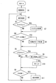
ステップS8の各動作モード処理では、図14のステップS21でスプール3の回転方向が糸繰り出し方向か否かを判断する。この判断は、スプールセンサ102のいずれのリードスイッチが先にパルスを発したか否かにより判断する。スプール3の回転方向が糸繰り出し方向と判断するとステップS21からステップS22に移行する。ステップS22では、スプールセンサ102から出力されるパルスの計数値が減少する毎に計数値に基づきリール制御部100内に記憶された水深と計数値との関係を示すデータを読み出し水深LXを算出する。この水深がステップS2の表示処理で表示される。   In each operation mode process in step S8, it is determined in step S21 in FIG. 14 whether or not the rotation direction of the spool 3 is the yarn feeding direction. This determination is made based on which reed switch of the spool sensor 102 has issued a pulse first. When the rotation direction of the spool 3 is determined to be the yarn feeding direction, the process proceeds from step S21 to step S22. In step S22, every time the count value of the pulse output from the spool sensor 102 decreases, data indicating the relationship between the water depth and the count value stored in the reel control unit 100 is read based on the count value and the water depth LX is calculated. . This water depth is displayed in the display process of step S2.

ステップS23では、糸送りモードか否かを判断する。ステップS24では、棚停止モードか否かを判断する。ステップS25では、他のモードか否かを判断する。他のモードではない場合には、各動作モード処理を終わりメインルーチンに戻る。   In step S23, it is determined whether or not the yarn feeding mode is set. In step S24, it is determined whether or not the shelf stop mode. In step S25, it is determined whether or not another mode is selected. If it is not in another mode, each operation mode process is terminated and the process returns to the main routine.

糸送りモードのときには、ステップS23からステップS26に移行する。ステップS26では、水深LXが6m以上か否かを判断する。糸送りモードでは、最初からモータ4を正転させるのではなく、釣り糸が確実に繰り出されていると判断できる水深まで釣り糸の繰り出しを待つ。水深LXが6m以上の場合には、ステップS27に移行してモータ4を正転させる。これにより、前述したように遊星歯車機構40とスプール3との摩擦が小さくなり、スプール3がより高速で糸繰り出し方向に回転する。水深LXが6m未満のときはステップS27をスキップする。   In the yarn feed mode, the process proceeds from step S23 to step S26. In step S26, it is determined whether the water depth LX is 6 m or more. In the line feed mode, the motor 4 is not normally rotated from the beginning, but waits for the fishing line to be fed to a water depth at which it can be determined that the fishing line has been reliably fed. When the water depth LX is 6 m or more, the process proceeds to step S27 and the motor 4 is rotated forward. As a result, as described above, the friction between the planetary gear mechanism 40 and the spool 3 is reduced, and the spool 3 rotates in the yarn unwinding direction at a higher speed. When the water depth LX is less than 6 m, step S27 is skipped.

棚停止モードと判断するステップS24からステップS28に移行する。ステップS28では、得られた水深LXが棚位置Mに一致したか、つまり、仕掛けが棚に到達したか否かを判断する。棚位置は、前述した所定時間以上の停止による自動セットの他に、仕掛けが棚に到達したときに位置設定スイッチMSを押すことでセットされる。仕掛けが棚位置に到達するとステップS28からステップS29に移行する。ステップS29では、仕掛けが棚にあることを報知するためにブザー103を鳴らす。ステップS30では、モータ4を所定時間逆転させる。これにより、前述した動作で第1クラッチ戻し機構11によりクラッチ切換機構8を介してクラッチ機構7をクラッチオン状態に戻す。これにより、スプールの糸繰り出し方向の回転が停止する。水深LXが棚位置Mに統括していない場合はステップS29、S30をスキップする。他のモードと判断するとステップS25からステップS31に移行し、設定された他のモード処理を実行する。   The process proceeds from step S24 for determining the shelf stop mode to step S28. In step S28, it is determined whether the obtained water depth LX matches the shelf position M, that is, whether the device has reached the shelf. The shelf position is set by pressing the position setting switch MS when the device reaches the shelf, in addition to the above-described automatic setting by stopping for a predetermined time or more. When the device reaches the shelf position, the process proceeds from step S28 to step S29. In step S29, the buzzer 103 is sounded to notify that the device is on the shelf. In step S30, the motor 4 is reversely rotated for a predetermined time. Accordingly, the first clutch return mechanism 11 returns the clutch mechanism 7 to the clutch-on state via the clutch switching mechanism 8 in the above-described operation. As a result, the rotation of the spool in the yarn unwinding direction stops. If the water depth LX is not integrated with the shelf position M, steps S29 and S30 are skipped. If it is determined that the mode is another mode, the process proceeds from step S25 to step S31, and the set other mode process is executed.

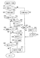
スプール3の回転が糸巻き取り方向と判断するとステップS21からステップS32に移行する。ステップS32では、スプールセンサ102の計数値が増加する毎にリール制御部100内に記憶されたデータを読み出し水深LXを算出する。この水深がステップS2の表示処理で表示される。ステップS33では、水深が船縁停止位置に一致したか否かを判断する。船縁停止位置まで巻き取っていない場合にはメインルーチンに戻る。船縁停止位置に到達するとステップS33からステップS34に移行する。ステップS34では、仕掛けが船縁にあることを報知するためにブザー103を鳴らす。ステップS35では、モータ4をオフする。これにより魚が釣れたときに取り込みやすい位置に魚が配置される。この船縁停止位置は、たとえば水深6m未満で所定時間以上スプール3が停止しているとセットされる。   When the rotation of the spool 3 is determined to be the yarn winding direction, the process proceeds from step S21 to step S32. In step S32, every time the count value of the spool sensor 102 increases, the data stored in the reel control unit 100 is read and the water depth LX is calculated. This water depth is displayed in the display process of step S2. In step S33, it is determined whether or not the water depth matches the ship edge stop position. If it has not been wound up to the ship edge stop position, it returns to the main routine. When the ship edge stop position is reached, the process proceeds from step S33 to step S34. In step S34, the buzzer 103 is sounded to notify that the device is on the shore. In step S35, the motor 4 is turned off. As a result, the fish is arranged at a position where it can be easily taken when the fish is caught. This ship edge stop position is set when, for example, the water depth is less than 6 m and the spool 3 is stopped for a predetermined time or more.

ここでは、モータ4の逆転により連動機構89を動作させてクラッチオン状態に復帰する際にだけ、押圧機構88により連動機構89を押圧して押圧機構88を離反させているので、モータ4と連動機構89とを常時連動させる必要がなくなる。このため、クラッチ切換機構8を手動操作してクラッチ機構7をクラッチオフ状態からクラッチオン状態に切り換える際にはモータ4が回らなくなり、手動による復帰操作を行いやすくなる。   Here, only when the interlocking mechanism 89 is operated by reverse rotation of the motor 4 to return to the clutch-on state, the interlocking mechanism 89 is pressed by the pressing mechanism 88 to separate the pressing mechanism 88. It is not necessary to always link the mechanism 89. For this reason, when the clutch switching mechanism 8 is manually operated to switch the clutch mechanism 7 from the clutch-off state to the clutch-on state, the motor 4 does not rotate, and a manual return operation is facilitated.

また、モータ4が正転すると、爪制御機構84により揺動爪82が爪車81をかわす位置まで揺動するので、モータ4の正転時に逆転防止のための揺動爪82が振動しなくなり静音化を図ることができる。   When the motor 4 rotates forward, the claw control mechanism 84 swings the swing claw 82 to a position where the claw wheel 81 is displaced, so that the swing claw 82 for preventing reverse rotation does not vibrate when the motor 4 rotates forward. Silence can be achieved.

さらに、押圧機構88の押圧部材91と出力軸30との間にローラクラッチ90を介装して出力軸30の正転を押圧部材91に伝達しないようにしたので、糸送りモードのときに、押圧部材91が連動機構88に接触しても押圧しなくなり、糸送りモードを円滑に実施できる。   Furthermore, since the roller clutch 90 is interposed between the pressing member 91 of the pressing mechanism 88 and the output shaft 30 so that the forward rotation of the output shaft 30 is not transmitted to the pressing member 91, in the yarn feeding mode, Even if the pressing member 91 comes into contact with the interlocking mechanism 88, it is not pressed, and the yarn feeding mode can be smoothly implemented.

さらに、ここでは、第1カバー部材14側に突出する爪制御機構84やローラクラッチ90や押圧部材91を覆う第3カバー部材28が、第1カバー部材14の貫通孔14bを貫通して外方に突出するように形成されている。このため、従来のように爪制御機構84やローラクラッチ90や押圧部材91全体を第1カバー部材14で覆う場合に比して、リール全体の大型化を防止することができる。   Furthermore, here, the third cover member 28 that covers the claw control mechanism 84, the roller clutch 90, and the pressing member 91 that protrudes toward the first cover member 14 passes through the through hole 14b of the first cover member 14 and outwards. It is formed so as to protrude. For this reason, compared with the case where the claw control mechanism 84, the roller clutch 90, and the whole pressing member 91 are covered with the 1st cover member 14 conventionally, the enlargement of the whole reel can be prevented.

〔他の実施形態〕
(a) 前記実施形態では、爪制御機構84を設けて静音化を図ったが、爪制御機構を設けなくてもよい。また、糸送りモードを円滑に実施するためにローラクラッチ90を押圧部材91に装着したが、糸送りモードが不要の場合には、ローラクラッチ90を設ける必要はない。
[Other Embodiments]
(A) In the embodiment described above, the claw control mechanism 84 is provided to reduce noise, but the claw control mechanism may not be provided. Further, the roller clutch 90 is mounted on the pressing member 91 in order to smoothly execute the yarn feeding mode. However, when the yarn feeding mode is not necessary, the roller clutch 90 is not necessary.

(b) 前記実施形態では、スプール3内にモータ4を配置したが、スプール3外にモータ4が配置される電動リールにも本発明を適用できる。この場合も前記実施形態と同様にモータ4の出力軸に第1ワンウェイクラッチや押圧機構を設けるとともに、クラッチ切換機構に連動する連動機構を設ければよい。   (B) In the above embodiment, the motor 4 is disposed in the spool 3, but the present invention can also be applied to an electric reel in which the motor 4 is disposed outside the spool 3. In this case as well, a first one-way clutch and a pressing mechanism may be provided on the output shaft of the motor 4 as in the above embodiment, and an interlocking mechanism that interlocks with the clutch switching mechanism may be provided.

(c) 前記実施形態では、第3カバー部材28は、第1側板16の膨出部27に着脱自在に装着されていたが、膨出部27を設けないで第1側板16に着脱自在に装着する構成にしてもよい。なお、この場合には、第3カバー部材28の内部には、モータ4の端部が配置される構成になる。   (C) In the above-described embodiment, the third cover member 28 is detachably attached to the bulging portion 27 of the first side plate 16. However, the third cover member 28 can be detachably attached to the first side plate 16 without providing the bulging portion 27. You may make it the structure to mount | wear. In this case, the end of the motor 4 is arranged inside the third cover member 28.

(d) 前記実施形態では、第1クラッチ戻し機構11や第2クラッチ戻し機構12を設けた構成であったが、これらを有さない構成にしてもよい。なお、この場合には、第3カバー部材28の内部には、ローラクラッチ90のみ配置される構成になる。   (D) In the above embodiment, the first clutch return mechanism 11 and the second clutch return mechanism 12 are provided. However, the first clutch return mechanism 11 and the second clutch return mechanism 12 may be omitted. In this case, only the roller clutch 90 is arranged inside the third cover member 28.

本発明の一実施形態による電動リールの斜視図。The perspective view of the electric reel by one Embodiment of this invention. 前記電動リールの縦断面図。The longitudinal cross-sectional view of the said electric reel. モータ装着部分の断面拡大図。The cross-sectional enlarged view of a motor mounting part. クラッチオン時のハンドル側の側カバーを外した状態の側面図。The side view of the state which removed the side cover by the side of a handle at the time of clutch on. クラッチオフ時のハンドル側の側カバーを外した状態の側面図。The side view of the state which removed the side cover by the side of a handle at the time of clutch off. クラッチオン時のハンドルと逆側の側カバーを外した状態の側面図。The side view of the state which removed the side cover on the opposite side to the handle at the time of clutch-on. 第1クラッチ戻し機構を中心とした分解斜視図。The disassembled perspective view centering on a 1st clutch return mechanism. クラッチオン時の第1ワンウェイクラッチ及び第1クラッチ戻し機構を中心とした側面拡大図。The side surface enlarged view centering on the 1st one-way clutch and the 1st clutch return mechanism at the time of a clutch-on. クラッチオフ時の第1ワンウェイクラッチ及び第1クラッチ戻し機構を中心とした側面拡大図。The side surface enlarged view centering on the 1st one-way clutch and the 1st clutch return mechanism at the time of clutch-off. モータ正転時の第1ワンウェイクラッチ及び第1クラッチ戻し機構を中心とした側面拡大図。The side surface enlarged view centering on the 1st one-way clutch and the 1st clutch return mechanism at the time of motor forward rotation. カウンタの平面拡大図。The plane enlarged view of a counter. リールの制御系の構成を示すブロック図。The block diagram which shows the structure of the control system of a reel. リール制御部のメインルーチンの制御フローチャート。The control flowchart of the main routine of a reel control part. リール制御部の各動作モード処理の制御フローチャート。7 is a control flowchart of each operation mode process of the reel control unit.

2 リール本体
3 スプール
4 モータ
5 カウンタ
6 回転伝達機構
7 クラッチ機構
8 クラッチ切換機構
9 第1ワンウェイクラッチ
10 第2ワンウェイクラッチ
11 第1クラッチ戻し機構
12 第2クラッチ戻し機構
13 フレーム
14 第1カバー部材
15 第2カバー部材
16 第1側板
17 第2側板
28 第3カバー部材
30 出力軸
81 爪車
82 揺動爪
84 爪制御機構
85 静音カム
86 回動機構部
88 押圧機構
89 連動機構
90 ローラクラッチ
91 押圧部材
93 連結軸
94 第1レバー部材
95 第2レバー部材
96 進退部材
2 reel body 3 spool 4 motor 5 counter 6 rotation transmission mechanism 7 clutch mechanism 8 clutch switching mechanism 9 first one-way clutch 10 second one-way clutch 11 first clutch return mechanism 12 second clutch return mechanism 13 frame 14 first cover member 15 Second cover member 16 First side plate 17 Second side plate 28 Third cover member 30 Output shaft 81 Claw wheel 82 Oscillating claw 84 Claw control mechanism 85 Silent cam 86 Turning mechanism portion 88 Pressing mechanism 89 Interlocking mechanism 90 Roller clutch 91 Pressing Member 93 Connecting shaft 94 First lever member 95 Second lever member 96 Advance / Retreat member

Claims (8)

釣りに用いられる電動リールであって、
リール本体と、
前記リール本体に装着されたハンドルと、
前記リール本体に回転自在に支持された糸巻き用のスプールと、
前記スプールを回転させるモータと、
前記モータ及び前記ハンドルの回転を前記スプールに伝達する回転伝達機構と、
前記回転伝達機構の途中に設けられ、前記スプールが自由回転可能状態となるクラッチオフ状態と、糸巻取可能状態となるクラッチオン状態とに切り換え可能なクラッチ機構とを備え、
前記リール本体は、
間隔を隔てて配置され間に前記スプールが配置された第1側板及び第2側板と、前記第1側板及び前記第2側板を連結する連結部とを有するフレームと、
前記第1側板の外方を覆う第1カバー部材と、
前記第2側板の外方を覆いかつ前記ハンドルが装着された第2カバー部材と、
前記第1側板の外方に少なくとも前記モータの出力軸の突出部分を覆うように装着固定され、第1カバー部材を貫通して外方に突出する第3カバー部材とを有している、電動リール。
An electric reel used for fishing,
The reel body,
A handle attached to the reel body;
A spool for spooling rotatably supported on the reel body;
A motor for rotating the spool;
A rotation transmission mechanism for transmitting rotation of the motor and the handle to the spool;
A clutch mechanism provided in the middle of the rotation transmission mechanism and capable of switching between a clutch-off state in which the spool is freely rotatable and a clutch-on state in which the yarn can be wound;
The reel body is
A frame having a first side plate and a second side plate which are arranged at intervals and in which the spool is arranged, and a connecting portion which connects the first side plate and the second side plate;
A first cover member covering the outside of the first side plate;
A second cover member covering the outside of the second side plate and having the handle attached thereto;
A third cover member that is mounted and fixed on the outer side of the first side plate so as to cover at least the protruding portion of the output shaft of the motor and protrudes outwardly through the first cover member; reel.
前記モータの出力軸に回転不能に装着され、前記モータの糸繰り出し方向の逆転を禁止可能なワンウェイクラッチをさらに備え、
前記第3カバー部材は、前記ワンウェイクラッチを覆うように装着されている、請求項1に記載の電動リール。
A one-way clutch that is non-rotatably attached to the output shaft of the motor and that can prohibit reverse rotation of the motor in the yarn pay-out direction;
The electric reel according to claim 1, wherein the third cover member is mounted so as to cover the one-way clutch.
前記ワンウェイクラッチは、前記モータの出力軸に回転不能に装着された爪車と、前記爪車に対して接離しかつ前記爪車に向けて付勢される揺動爪とを有しており、
前記クラッチ機構を前記クラッチオフ状態と前記クラッチオン状態とに切り換えるクラッチ切換機構と、
前記爪車と並べて前記モータの出力軸に装着され少なくとも前記モータの逆転に連動して回転する押圧機構、及び前記クラッチ切換機構の動作に連動して動作し、前記クラッチ切換機構により前記クラッチ機構が前記クラッチオフ状態に切り換えられると前記揺動爪に接触して前記揺動爪を前記爪車から離反させ前記モータを逆転許可状態にするとともに前記押圧機構による押圧が可能な位置に移動し、その状態で前記モータが逆転すると前記押圧機構により押圧されて押圧が不能な位置に移動するとともに前記クラッチ切換機構を介して前記クラッチ機構を前記クラッチオン状態にする連動機構を有する第1クラッチ戻し機構とをさらに備え、
前記第3カバー部材は、前記押圧機構を覆うように装着されている、請求項2に記載の電動リール。
The one-way clutch has a claw wheel that is non-rotatably attached to the output shaft of the motor, and a swinging claw that is in contact with and away from the claw wheel and is biased toward the claw wheel,
A clutch switching mechanism for switching the clutch mechanism between the clutch-off state and the clutch-on state;
A pressing mechanism that is mounted on the output shaft of the motor side by side with the claw wheel and rotates in conjunction with at least the reverse rotation of the motor, and operates in conjunction with the operation of the clutch switching mechanism. When switched to the clutch-off state, the swinging claw comes into contact with the swinging claw to move the swinging claw away from the claw wheel so that the motor is allowed to reversely rotate and moves to a position where pressing by the pressing mechanism is possible. A first clutch return mechanism having an interlocking mechanism for moving the clutch mechanism to the clutch-on state via the clutch switching mechanism while moving to a position where pressing is impossible by the pressing mechanism when the motor reversely rotates in the state; Further comprising
The electric reel according to claim 2, wherein the third cover member is mounted so as to cover the pressing mechanism.
前記ワンウェイクラッチは、前記モータが糸巻取方向に正転すると前記爪車をかわす位置まで前記揺動爪を前記逆転許可位置側に揺動させる制御機構をさらに有しており、
前記第3カバー部材は、前記制御機構を覆うように装着されている、請求項3に記載の電動リール。
The one-way clutch further includes a pawl control mechanism that swings the swinging pawl to the reverse rotation permission position side until the position where the motor rotates forward in the yarn winding direction.
The electric reel according to claim 3, wherein the third cover member is mounted so as to cover the claw control mechanism.
前記制御機構は、前記モータの出力軸に回転自在に摩擦係合し外周に前記揺動爪を押圧する押圧部を有する回転部材と、前記回転部材の回動範囲を規制する回動規制部とを有している、請求項4に記載の電動リール。 The claw control mechanism includes a rotating member having a pressing portion that frictionally engages with an output shaft of the motor and presses the swinging claw on an outer periphery, and a rotation restricting portion that restricts a rotation range of the rotating member. The electric reel according to claim 4, comprising: 前記連動機構は、前記揺動爪に接触して前記揺動爪を前記爪車から離反させるとともに前記押圧機構による押圧が可能な解放位置と、前記揺動爪から離反するとともに前記押圧機構による押圧が不能な係止位置とに移動自在に前記リール本体に装着され、前記クラッチ切換機構により前記クラッチ機構がクラッチオフ状態に切り換えられると、前記クラッチ切換機構に連動して前記係止位置から前記解放位置に移動して前記揺動爪を前記爪車に接触させ、
前記押圧機構は、前記連動機構が前記解放位置に配置された状態で前記モータが逆転すると前記連動機構を押圧して前記係止位置に向けて移動させる、請求項から5のいずれか1項に記載の電動リール。
Pressing by the pressing mechanism with the interlocking mechanism includes a release position capable pressed by the pressing mechanism causes is separated from the ratchet wheel of the swing pawl in contact with the swing pawl, away from the swing claw When the clutch mechanism is switched to a clutch-off state by the clutch switching mechanism, the release from the locking position is interlocked with the clutch switching mechanism. Moved to a position to bring the rocking claw into contact with the claw wheel,
6. The pressing mechanism according to claim 3 , wherein the pressing mechanism presses and moves the interlocking mechanism toward the locking position when the motor reverses in a state where the interlocking mechanism is disposed at the release position. The electric reel as described in.
前記クラッチ切換機構は、前記第2カバー部材と前記第2側板の間の空間に配置され、
前記連動機構は、
前記第1側板及び前記第2側板を貫通して回動自在に装着された連結軸と、
前記連結軸の第2側板側の突出端に回転不能に装着され前記クラッチ切換機構に先端が連結されて前記クラッチ切換機構の切換動作に連動して揺動する第1レバー部材と、
前記連結軸の前記第1側板側の突出端に回転不能に装着された第2レバー部材と、
前記揺動爪に接触する第1接触部と前記押圧機構が接触する第2接触部とを有し、前記第2レバー部材の先端に連結され前記揺動爪及び押圧機構に向けて進退する進退部材とを有している、請求項から6のいずれか1項に記載の電動リール。
The clutch switching mechanism is disposed in a space between the second cover member and the second side plate,
The interlocking mechanism is
A connecting shaft that is pivotably mounted through the first side plate and the second side plate;
A first lever member that is non-rotatably attached to the projecting end of the connecting shaft on the second side plate side, has a tip connected to the clutch switching mechanism, and swings in conjunction with the switching operation of the clutch switching mechanism;
A second lever member mounted non-rotatably on the protruding end of the connecting shaft on the first side plate side;
The first contact portion that contacts the swinging claw and the second contact portion that contacts the pressing mechanism, and is connected to the tip of the second lever member to advance and retreat toward the swinging claw and the pressing mechanism. The electric reel according to claim 3 , further comprising a member.
前記ハンドルの糸巻取方向の回転に連動して前記クラッチ切換機構を介して前記クラッチ機構をクラッチオフ状態からクラッチオン状態に戻す第2クラッチ戻し機構をさらに備えている、請求項から7のいずれか1項に記載の電動リール。 Via the clutch switching mechanism in conjunction with rotation of the yarn winding direction of said handle and further comprising a second clutch return mechanism for returning the clutch-on state the clutch mechanism from the clutch-off state, one of claims 3 to 7 The electric reel according to claim 1.
JP2004117789A 2004-04-13 2004-04-13 Electric reel Expired - Fee Related JP4366232B2 (en)

Priority Applications (1)

Application Number Priority Date Filing Date Title
JP2004117789A JP4366232B2 (en) 2004-04-13 2004-04-13 Electric reel

Applications Claiming Priority (1)

Application Number Priority Date Filing Date Title
JP2004117789A JP4366232B2 (en) 2004-04-13 2004-04-13 Electric reel

Publications (2)

Publication Number Publication Date
JP2005295905A JP2005295905A (en) 2005-10-27
JP4366232B2 true JP4366232B2 (en) 2009-11-18

Family

ID=35328200

Family Applications (1)

Application Number Title Priority Date Filing Date
JP2004117789A Expired - Fee Related JP4366232B2 (en) 2004-04-13 2004-04-13 Electric reel

Country Status (1)

Country Link
JP (1) JP4366232B2 (en)

Also Published As

Publication number Publication date
JP2005295905A (en) 2005-10-27

Similar Documents

Publication Publication Date Title
JP5746841B2 (en) Clutch control device for double bearing reel
TW200948267A (en) Reverse prevention mechanism for lever drag reel
CN105265401B (en) Dual-bearing reel and clutch mechanism for dual-bearing reel
CN104115797B (en) Dual-bearing reel
JP2014212739A5 (en)
JP4610253B2 (en) Clutch return device for fishing reel
JP4366232B2 (en) Electric reel
JP4522063B2 (en) Electric reel
TWI336613B (en)
TWI326582B (en)
KR102611460B1 (en) Electrical fishing reel
JP4366146B2 (en) Electric reel
JP2005087111A (en) Switching device for fishing reel
JP4773071B2 (en) Electric reel
JP2005087111A5 (en)
JP4266806B2 (en) Electric reel motor control device
JP2005269929A (en) Motor controller of electric reel
JP2001128595A (en) Spinning reel
JP4451652B2 (en) Electric reel motor control device
JP3546142B2 (en) Fishing reel
JP2008035817A (en) Spool for spinning reel
JP4451651B2 (en) Electric reel motor control device
JP2005117902A (en) Electric reel
JP6143657B2 (en) Fishing reel
JP4785372B2 (en) Fishing reel one-way clutch

Legal Events

Date Code Title Description
A621 Written request for application examination

Free format text: JAPANESE INTERMEDIATE CODE: A621

Effective date: 20070307

A977 Report on retrieval

Free format text: JAPANESE INTERMEDIATE CODE: A971007

Effective date: 20090515

A131 Notification of reasons for refusal

Free format text: JAPANESE INTERMEDIATE CODE: A131

Effective date: 20090609

A521 Written amendment

Free format text: JAPANESE INTERMEDIATE CODE: A523

Effective date: 20090617

RD02 Notification of acceptance of power of attorney

Free format text: JAPANESE INTERMEDIATE CODE: A7422

Effective date: 20090617

TRDD Decision of grant or rejection written
A01 Written decision to grant a patent or to grant a registration (utility model)

Free format text: JAPANESE INTERMEDIATE CODE: A01

Effective date: 20090804

A01 Written decision to grant a patent or to grant a registration (utility model)

Free format text: JAPANESE INTERMEDIATE CODE: A01

A61 First payment of annual fees (during grant procedure)

Free format text: JAPANESE INTERMEDIATE CODE: A61

Effective date: 20090824

FPAY Renewal fee payment (event date is renewal date of database)

Free format text: PAYMENT UNTIL: 20120828

Year of fee payment: 3

R150 Certificate of patent or registration of utility model

Free format text: JAPANESE INTERMEDIATE CODE: R150

FPAY Renewal fee payment (event date is renewal date of database)

Free format text: PAYMENT UNTIL: 20120828

Year of fee payment: 3

FPAY Renewal fee payment (event date is renewal date of database)

Free format text: PAYMENT UNTIL: 20130828

Year of fee payment: 4

R250 Receipt of annual fees

Free format text: JAPANESE INTERMEDIATE CODE: R250

R250 Receipt of annual fees

Free format text: JAPANESE INTERMEDIATE CODE: R250

R250 Receipt of annual fees

Free format text: JAPANESE INTERMEDIATE CODE: R250

R250 Receipt of annual fees

Free format text: JAPANESE INTERMEDIATE CODE: R250

R250 Receipt of annual fees

Free format text: JAPANESE INTERMEDIATE CODE: R250

LAPS Cancellation because of no payment of annual fees