CN104115797B - Dual-bearing reel - Google Patents
Dual-bearing reel Download PDFInfo
- Publication number
- CN104115797B CN104115797B CN201410169903.2A CN201410169903A CN104115797B CN 104115797 B CN104115797 B CN 104115797B CN 201410169903 A CN201410169903 A CN 201410169903A CN 104115797 B CN104115797 B CN 104115797B
- Authority
- CN
- China
- Prior art keywords
- drag
- drive shaft
- handle
- dual
- bearing reel
- Prior art date
- Legal status (The legal status is an assumption and is not a legal conclusion. Google has not performed a legal analysis and makes no representation as to the accuracy of the status listed.)
- Active
Links
Images


Classifications
-
- A—HUMAN NECESSITIES
- A01—AGRICULTURE; FORESTRY; ANIMAL HUSBANDRY; HUNTING; TRAPPING; FISHING
- A01K—ANIMAL HUSBANDRY; CARE OF BIRDS, FISHES, INSECTS; FISHING; REARING OR BREEDING ANIMALS, NOT OTHERWISE PROVIDED FOR; NEW BREEDS OF ANIMALS
- A01K89/00—Reels
- A01K89/015—Reels with a rotary drum, i.e. with a rotating spool
- A01K89/01931—Spool or spool shaft details
-
- A—HUMAN NECESSITIES
- A01—AGRICULTURE; FORESTRY; ANIMAL HUSBANDRY; HUNTING; TRAPPING; FISHING
- A01K—ANIMAL HUSBANDRY; CARE OF BIRDS, FISHES, INSECTS; FISHING; REARING OR BREEDING ANIMALS, NOT OTHERWISE PROVIDED FOR; NEW BREEDS OF ANIMALS
- A01K89/00—Reels
- A01K89/015—Reels with a rotary drum, i.e. with a rotating spool
- A01K89/0192—Frame details
Abstract
The invention provides a dual-bearing reel. In the drag mechanism disposed around the drive shaft, the drag can be easily reduced. A drag mechanism (23) of a dual-bearing reel (100) brakes rotation of a spool (12) in a line unwinding direction. The drag mechanism (23) has a star drag device (36) and a friction mechanism (37). The star drag device (36) is engaged with the outer peripheral surface of the drive shaft (30) so as to be rotatable integrally and relatively rotatable, and is movable in the axial direction relative to the drive shaft (30) by relative rotation with the drive shaft (30). The friction mechanism (37) is disposed on the drive shaft (30), and the drag force varies according to the amount of movement of the star drag device (36) in the axial direction. The star drag device (36) is moved in a direction in which the drag force increases by being relatively rotated in a direction opposite to the wire winding direction of the handle (2) with respect to the drive shaft (30).
Description
Technical Field
The present invention relates to a fishing reel, and more particularly to a dual-bearing reel that discharges a fishing line in the forward direction.
Background
A dual-bearing reel is a reel that winds a fishing line by spinning a spool. A brake device called a drag mechanism is provided on the dual-bearing reel. The drag mechanism is provided to brake the rotation of the spool in the line-releasing direction without applying an excessive tension to the fishing line. As the drag mechanism, a so-called star drag mechanism provided around a drive shaft connected to a handle so as to be rotatable integrally is known (for example, see patent document 1).
A drag mechanism of a dual bearing reel adjusts drag by an operating member that is screwed to a male screw portion formed on a drive shaft, and is called a star drag device. The operating member has radially arranged operating portions, and when a user grips the operating portions and turns the operating member in the same direction as the thread winding direction of the handle, drag force (braking force for braking the rotation of the spool in the thread unwinding direction) is increased, and when the operating member is turned in the direction opposite to the thread winding direction, the drag force is decreased. This is the same in a dual-bearing reel in which the handle is disposed on the right-hand side of the reel body in plan view, and a dual-bearing reel in which the handle is disposed on the left-hand side.
Patent document 1: japanese patent laid-open No. 2000-069889.
In a fishing method called iron plate fishing, which is popular in recent years, in which a fishing line is gradually wound while a pulling operation is repeated, an operation of reducing a drag force is frequently performed. In order to reduce drag, in conventional dual-bearing reels, it is necessary to depress the operating member with the thumb of the hand holding the handle and rotate the operating member in a direction opposite to the wire winding direction. Therefore, the operation of depressing the operation member is difficult, and the drag force cannot be easily weakened. This is particularly significant in the case where the drag force is set to be strong.
Disclosure of Invention
The present invention addresses the problem of easily reducing drag in a drag mechanism disposed around a drive shaft.
The dual-bearing reel of the present invention is a reel for releasing a fishing line in the forward direction. A dual-bearing reel includes a reel body, a handle, a spool, a rotation transmission mechanism, and a drag mechanism. The handle is provided on a side portion of the reel unit so as to be rotatable in a line winding direction. The spool rotates in the wire winding direction in conjunction with rotation of the handle in the wire winding direction. The rotation transmission mechanism has a drive shaft connected to the handle so as to be rotatable integrally therewith, and transmits rotation of the handle in the wire winding direction to the drum. The drag mechanism brakes rotation of the spool in the wire unwinding direction. The drag mechanism has an operating member and a friction mechanism. The operation member is engaged with an outer peripheral surface of the drive shaft so as to be rotatable integrally and relatively rotatable, and is movable in the axial direction relative to the drive shaft by relative rotation with the drive shaft. The friction mechanism is disposed on the drive shaft, and the drag force changes in accordance with the amount of movement of the operating member in the axial direction. The operating member is moved in a direction in which the drag force increases by being relatively rotated in a direction opposite to the wire winding direction of the handle with respect to the driving shaft.
In this dual-bearing reel, when the operating member is operated in a direction opposite to the thread winding direction of the handle, drag force is increased, and when operated in the thread winding direction, drag force is decreased. The drag force is increased when the operating member is pressed with a finger (e.g., thumb) of a hand holding the handle, and is decreased when the operating member is pulled with another finger (e.g., index finger). Here, since the drag force can be reduced by performing the same pulling operation as the operation of pulling the trigger with the fingers of the hand gripping the handle, the drag force can be easily reduced.
The handle may have an arm portion having a base end connected to the drive shaft so as to be integrally rotatable, and a grip portion rotatably attached to a distal end of the arm portion. In this case, even with a single grip in which the grip portion is disposed at a position farther from the operating member than with a double grip having two grip portions, the drag force can be reduced by a pulling operation with the index finger longer than the thumb. Therefore, the drag force can be easily weakened regardless of the form of the handle.
The drive shaft may have a male screw portion on an outer peripheral surface thereof, and the operation member may have an inner peripheral surface thereof and a female screw portion screwed with the male screw portion on an inner peripheral surface thereof. In this case, the operating member is engaged with the drive shaft by the screw engagement with a small amount of rotational movement relative to the operating member, and therefore the drag force can be finely adjusted.
The handle may be provided on the right side of the reel unit in plan view, and the male screw portion and the female screw portion may be left-handed screws. In this case, in the dual-bearing reel of the right handle, when the operation member is operated in the wire winding direction of the handle by the action of the left-hand thread, the female thread portion of the operation member moves in the direction away from the friction portion, and the drag force can be reduced.
The handle may be provided on the left side of the reel unit in plan view, and the male screw portion and the female screw portion may be right-handed screws. In this case, in the dual-bearing reel of the left handle, when the operating member is operated in the wire winding direction of the handle by the action of the right-handed thread, the female thread portion of the operating member moves in a direction away from the friction portion, and the drag force can be reduced.
The dual-bearing reel may further include an elastic member disposed between the operating member and the friction mechanism. In this case, the elastic member is compressed by the movement of the operating member in the axial direction, and the drag force can be increased or decreased according to the amount of compression. Thus, when the operation member is relatively rotated with respect to the drive shaft, the drag force can be finely adjusted.
According to the present invention, since the drag force can be reduced by performing the same pulling operation as the trigger pulling operation with the fingers of the hand gripping the handle, the drag force can be easily reduced.
Drawings
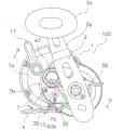
Fig. 1 is a side view of a dual-bearing reel according to embodiment 1 of the present invention.
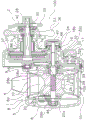
Fig. 2 is a sectional view taken along a sectional line II-II of fig. 1.
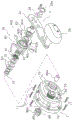
Fig. 3 is an exploded perspective view showing the structure of the friction portion.
Fig. 4 is an exploded perspective view showing the star drag device and components between the star drag device and the friction portion.
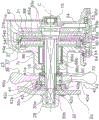
Fig. 5 is a cross-sectional enlarged view of fig. 2 showing the structure around the drive shaft.
Fig. 6 is a view corresponding to fig. 5 of the dual-bearing reel of embodiment 2.
Description of the reference numerals
1a reel body; 2, a handle; 2a an arm part; 2b a handle part; 12, winding a drum; 19 a rotation transmitting mechanism; 23 a drag mechanism; 30a drive shaft; 30c a 2 nd male screw portion (an example of a male screw portion); 36 star drag device (an example of an operation member).
Detailed Description
< embodiment 1 >
In fig. 1 and 2, a dual-bearing reel 100 to which the 1 st embodiment of the present invention is applied is a circular reel for use in bait cast fishing, teppanyaking, and the like. The dual-bearing reel 100 includes: a reel body 1; a handle 2 for spool rotation disposed on the side of the reel unit 1; and a spool 12 rotatably mounted inside the reel unit 1.
In the following description, the front, rear, left, and right are shown in a state in which the fishing line is being paid out in a forward direction in a state in which the dual-bearing reel 100 is assembled to a fishing rod, and in a state in which the dual-bearing reel 100 is viewed from the rear.
< handle >
The handle 2 is a single-handle-shaped member having a plate-shaped arm portion 2a and a grip 2b rotatably attached to a distal end of the arm portion 2 a. As shown in fig. 2, the base end of the arm portion 2a is integrally rotatably fitted to the tip end of a drive shaft 30 described later, and is fastened to the drive shaft 30 by a nut 28. As shown in fig. 4, the nut 28 is locked by a stopper 28a screwed to the arm portion 2 a.
< reel body >
As shown in fig. 2, the reel unit 1 is a metal member made of, for example, aluminum alloy, magnesium alloy, or the like, and includes a frame 5, and a 1 st side cover 6 and a 2 nd side cover 7 attached to both sides of the frame 5. The spool 12 is rotatably mounted inside the reel unit 1 via a spool shaft 20. The frame 5 has: a pair of left and right annular 1 st and 2 nd side plates 8 and 9 disposed at a predetermined interval; and a plurality of coupling portions 10 coupling the 1 st side plate 8 and the 2 nd side plate 9. The 1 st side panel 8 has a smaller diameter than the 2 nd side panel 9.
The plurality of coupling portions 10 are formed integrally with the 1 st side plate 8 and the 2 nd side plate 9. As shown in fig. 1, a rod fitting leg portion 4 made of metal, such as aluminum alloy, which is long in the front-rear direction and used for fitting the reel to the fishing rod is fixed by caulking to a coupling portion 10 formed on the lower side.
The 1 st side cover 6 is circular when viewed from the spool axial outer side and is formed integrally with the 1 st side plate 8. The 1 st-side cover 6 rotatably supports a left end of a spool shaft 20 described later.
As shown in fig. 1 and 4, the 2 nd-side cover 7 includes a circular portion 7a and a bulging portion 7b projecting outward and radially outward from the circular portion 7 a. The 2 nd-side cover 7 is fastened to the mechanism attachment plate 34 by a plurality of (e.g., 5) screw members 11.
The bulging portion 7b is formed in a deformed oblong shape. The bulging portion 7b is formed with a cylindrical 1 st boss portion 7c that supports the drive shaft 30. A circular opening 7d is formed behind the 1 st boss portion 7 c. A label attaching portion 7e formed by a slight recess is formed behind and around the 1 st boss portion 7c including the opening 7 d. The opening 7d is provided to facilitate assembly of a drag sound generation mechanism 27 described later. And also as a drain hole and an oil fill port. A sign 35 is attached to sign attaching portion 7 e. Therefore, in the state where label 35 is attached, opening 7d is closed by label 35 and cannot be seen from the outside. The sign 35 is attached to the sign attaching portion 7e by 2 screw members 39, for example. A 2 nd boss portion 7f on which one end of the spool shaft 20 is disposed is formed above the label attaching portion 7 e.
As shown in fig. 2, the 2 nd side cover 7 rotatably supports the drive shaft 30. A clutch lever 17 is attached to the rear of the 2 nd side cover 7. A mechanism mounting plate 34 constituting the frame 5 is disposed between the 2 nd side cover 7 and the 2 nd side plate 9.
As shown in fig. 2, the rotation transmission mechanism 19, the clutch mechanism 21, the clutch control mechanism 22, the drag mechanism 23, the throwing control mechanism 24, and the drag sounding mechanism 27 are disposed between the 2 nd side cover 7 and the mechanism mounting plate 34. The rotation transmission mechanism 19 transmits the rotation of the handle 2 in the wire winding direction to the drum 12. The clutch mechanism 21 connects and disconnects the handle 2 and the spool 12. When the clutch mechanism 21 is set to the clutch release state (disengaged state), the drum 12 is in a freely rotatable state. The clutch control mechanism 22 includes a clutch fork 33 and a clutch plate (not shown), and controls the clutch mechanism 21 to a clutch engaged state (coupled state) and a clutch disengaged state according to an operation of the clutch lever 17. The switching from the clutch disengaged state to the clutch engaged state can be performed not only by the clutch lever 17 but also by operating a return mechanism, not shown, by rotating the handle 2 in the wire winding direction.
The drag mechanism 23 brakes the rotation of the spool 12 in the wire unwinding direction. The cast control mechanism 24 adjusts the resistance to rotation of the drum 12. When the drag mechanism 23 is operated and the spool 12 is rotated in the wire feeding direction, the drag sounding mechanism 27 sounds. Further, a spool lock mechanism, not shown, that can lock and unlock the rotation of the spool 12 in the wire feeding direction is provided between the spool 12 and the 1 st side cover 6.
< reel >
As shown in fig. 2, the drum 12 has a pair of left and right disk-shaped flange portions 12a at both side portions, and a cylindrical bobbin portion 12b between the pair of flange portions 12 a. The outer peripheral surface of the left flange portion 12a in fig. 2 is disposed with a slight gap on the inner peripheral side of the opening 8a in order to prevent wire biting. The spool 12 is fixed to a spool shaft 20 that penetrates the inner peripheral side of the bobbin 12b so as to be unrotatable by, for example, serration coupling. The fixing method is not limited to the serration coupling, and various coupling methods such as key coupling and spline coupling may be used.
As shown in fig. 2, the spool shaft 20 is made of a non-magnetic metal such as SUS304, for example, and is disposed parallel to the drive shaft 30. The spool shaft 20 penetrates the 2 nd side plate 9 and extends to the 2 nd boss portion 7f of the 2 nd side cover 7. The spool shaft 20 is rotatably supported by the reel unit 1 via a 1 st bearing 26a and a 2 nd bearing 26b on both sides of the spool 12. A large diameter portion 20a is formed at the center of the spool shaft 20, and an engagement pin 29 constituting the clutch mechanism 21 is fixed to the large diameter portion 20 a. The engagement pin 29 passes through the large diameter portion 20a along the diameter thereof, and both ends thereof protrude in the radial direction.
A clutch lever 17 is swingably attached to the rear portion of the 2 nd side cover 7. The clutch lever 17 is coupled to a clutch control mechanism 22, and when the clutch lever 17 swings, the clutch mechanism 21 performs clutch engagement and clutch disengagement.
< rotation transmitting mechanism >
As shown in fig. 2, the rotation transmission mechanism 19 includes a drive shaft 30, a drive gear 31 fixed to the drive shaft 30, and a cylindrical pinion gear 32 meshed with the drive gear 31.
The drive shaft 30 is rotatably mounted to the mechanism mounting plate 34 and the 2 nd side cover 7 via the bearing 15 and the bearing 16. As shown in fig. 3 and 5, the drive shaft 30 has a plurality of rotation stoppers 30a formed by parallel cut surfaces formed on the outer circumferential surface. And a 1 st male screw portion 30b for fixing the arm portion 2a of the handle 2 and a 2 nd male screw portion 30c for adjusting the drag force of the drag mechanism 23 are formed. The 1 st male threaded portion 30b is a right-hand thread. The 2 nd male screw portion 30c is an example of a male screw portion, and the handle 2 is configured as a left-hand screw or a right-hand screw by being disposed on which side of the reel unit 1. In this embodiment, the handle 2 is disposed on the right side of the reel unit 1 in plan view, and therefore the 2 nd male thread portion 30c is a left-hand thread. This is because, in the operation direction of the star drag device 36 for adjusting the drag force of the drag mechanism 23, the operation direction of increasing the drag force is made to be the opposite direction to the wire winding direction of the handle 2. The star drag device 36 is an example of an operation member. As shown in fig. 3 and 5, the drive shaft 30 is prevented from rotating (reversing) in the wire unwinding direction by the roller-type 1 st one-way clutch 86 and the dog-type 2 nd one-way clutch 87.
As shown in fig. 5, the 1 st one-way clutch 86 is fitted between the 2 nd side cover 7 and the drive shaft 30. The 1 st one-way clutch has: an outer ring 86a non-rotatably attached to the 1 st boss portion 7c, the 1 st boss portion 7c being attached to the 2 nd cover 7 so as to protrude outward; an inner ring 86b non-rotatably coupled to the drive shaft 30; and rolling elements 86c capable of biting into between the outer ring 86a and the inner ring 86 b.
As shown in fig. 3, the 2 nd one-way clutch 87 has: a ratchet wheel 88 integrally rotatably fitted to one rotation stop portion 30a of the rotation stop portions 30a of the drive shaft 30; and a pawl 89 swingably attached to the mechanism attachment plate 34. As shown in fig. 3 and 5, the ratchet gear 88 is disposed on the back side of the drive gear 31 with the drag disk 65d interposed therebetween. The pawl 89 is swingably attached to a boss shaft, not shown, which is formed on the mechanism attachment plate 34 so as to protrude therefrom.
The drive gear 31 is rotatably attached to the drive shaft 30 and frictionally coupled to the drive shaft 30 via the drag mechanism 23. As shown in fig. 3, a circular housing recess 31a for housing the drag mechanism 23 is formed on the right side surface of the drive gear 31. A plurality of (e.g., 4) 1 st engaging recesses 31b, which are recessed substantially in a semicircular shape, are formed on the inner peripheral surface of the housing recess 31a to engage the rotating member 54, which will be described later, so as to be integrally rotatable. A plurality of (e.g., two) 2 nd engaging recessed portions 31c are formed between the two 1 st engaging recessed portions 31 b. The 1 st engaging recess 31b is larger in inner diameter than the 2 nd engaging recess 31 c. A retaining groove 31d for fitting a retaining member 62 described later is formed in the inner peripheral surface of the housing recess 31 a.
As shown in fig. 2, the pinion gear 32 is a cylindrical member extending from the outside to the inside of the 2 nd side plate 9, through which the spool shaft 20 penetrates at the center, and is attached to the spool shaft 20 so as to be movable in the axial direction. The left end side of the pinion gear 32 in fig. 2 is rotatably supported by the mechanism mounting plate 34 via a bearing 18a and is axially movable. The right end portion of the pinion gear 32 in fig. 2 is rotatably supported by the 2 nd boss portion 7f via a bearing 18b attached to the 2 nd boss portion 7 f. An engagement groove 32a that engages with the engagement pin 29 is formed in the left end portion of the pinion 32 in fig. 2. The engagement groove 32a and the engagement pin 29 constitute a clutch mechanism 21. A bearing 18a is disposed on the outer peripheral surface of the engagement groove 32 a. A small-diameter constricted portion 32b is formed adjacent to the engagement groove 32a, and a gear portion 32c that engages with the drive gear 31 is formed at an intermediate portion.
As shown in fig. 2, the clutch control mechanism 22 includes a clutch fork 33, and the clutch fork 33 engages with a constricted portion 32b of the pinion gear 32 to move the pinion gear 32 in the spool shaft 20 direction. The clutch lever 17 is swung from the clutch engagement position to the clutch disengagement position to move the clutch fork 33 to the right in fig. 2, thereby releasing the engagement of the engagement pin 29 and bringing it into the clutch disengagement state.
As shown in fig. 2, the throwing control mechanism 24 includes: a plurality of friction plates 46 disposed so as to sandwich both ends of the spool shaft 20; and a brake cap 47 for adjusting the clamping force of the friction plate 46 to the spool shaft 20. The friction plate 46 on the left side is fitted in the center of the 1 st side cover 6. The stopper cap 47 is screwed to the outer peripheral surface of the 2 nd boss portion 7f of the 2 nd side cover 7.
Drag mechanism
As shown in fig. 3, the drag mechanism 23 has a star drag device 36 and a friction mechanism 37 for adjusting drag by the star drag device 36. When the fishing line is pulled by a force exceeding the drag force adjusted by the star drag device 36, the drag mechanism 23 operates, and the reel 12 rotates in the line unwinding direction.
As shown in fig. 4 and 5, the star drag device 36 has: a main body 40 having a plurality of (e.g., 5) operation portions 40a arranged at intervals in a circumferential direction; a nut member 41 connected to the main body 40 so as to be movable in the axial direction and integrally rotatable; and a drag force operation sounding mechanism 42 sounded by a rotating operation of the star drag device 36. The main body 40 includes: a 1 st accommodation space 40b having a substantially rectangular cross section for accommodating the nut member 41 so as to be rotatable integrally therewith and movable in the axial direction; and a circular 2 nd accommodating space 40c arranged axially in line with the 1 st accommodating space 40b and having a larger diameter than the 1 st accommodating space 40 b. A later-described tone plate 42a of the drag operation tone mechanism 42 is rotatably mounted in the 2 nd accommodation space 40c so as to be prevented from coming out in the axial direction. The nut member 41 has a female screw portion 41a on the inner peripheral surface. The nut member 41 is urged by a spring member 43 of a coil spring system. The spring member 43 is disposed in a compressed state between the nut member 41 and the sound emitting board 42 a. The main body 40 is biased toward the arm 2a of the handle 2 by a spring member 43. Thus, even if the nut member 41 moves in the axial direction, the main body 40 does not move in the axial direction. Therefore, the interval between the main body portion 40 and the arm portion 2a is always constant.
The star drag device 36 rotates the main body 40 to move the nut member 41 in the axial direction of the drive shaft 30, thereby changing the drag force of the friction mechanism 37. That is, the drag force is weakened when the nut member 41 is located at a position distant from the friction mechanism 37 so as to be drawn on the upper side of the axial center C of the drive shaft 30 in fig. 5, and the drag force is strengthened when the nut member is located at a position close to the friction mechanism 37 so as to be drawn on the lower side of the axial center C in fig. 5. The nut member 41 presses the two disc springs 50 as elastic members via the washer 70. The disc spring 50 is disposed between the nut member 41 and the bearing 16, and transmits the spring force of the star drag device 36, which is changed by the axial movement of the nut member 41, to the friction mechanism 37 via the bearing 16 and the inner race 86b of the 1 st one-way clutch 86. The spring force of the coned disc spring 50 gradually changes according to the movement of the nut member 41 in the axial direction. This enables the drag force of the friction mechanism 37 to be finely adjusted.
As shown in fig. 4 and 5, the drag operation sounding mechanism 42 has: a sound-emitting plate 42a coupled to the rotation stop portion 30a of the drive shaft 30 so as to be rotatable integrally with the drive shaft 30; a hitting pin 42b which is accommodated in a recess 40d so as to be able to advance and retreat, the recess 40d being formed on a stepped surface between the 1 st accommodation space 40b and the 2 nd accommodation space 40c of the main body 40; and an urging member 42c accommodated in the recess 40d and urging the striking pin 42b toward the sound board 42 a. The sound emitting plate 42a has a plurality of sound emitting recesses 42d (see fig. 5) arranged at intervals in the circumferential direction on a surface opposite to the surface facing the arm portion 2 a. When the star drag device 36 is operated to rotate, the hitting pin 42b rotates around the drive shaft 30 together with the star drag device 36, and repeatedly collides with the sound generation recess 42d, so that the drag operation sound generation mechanism 42 generates sound.
As shown in fig. 3 and 5, the friction mechanism 37 is provided around the drive shaft 30. The friction mechanism 37 includes: a 1 st drag washer 51, a 2 nd drag washer 52 and a 3 rd drag washer 53 which are pressed by the nut member 41 of the star drag device 36. The 1 st drag washer 51 is engaged with the rotation stopper 30a of the drive shaft 30 and is connected to the drive shaft 30 so as to be rotatable integrally. The 1 st drag washer 51 is connected to the inner ring 86b of the 1 st one-way clutch 86 so as to be rotatable integrally therewith, and is in contact with the inner ring 86b so as to be pressable in the axial direction. Thereby, the inner ring 86b can rotate integrally with the drive shaft 30, and the 1 st drag washer 51 is pressed by the inner ring 86 b.
The 2 nd drag washer 52 is connected to the drive gear 31 so as to be integrally rotatable. The 2 nd drag washer 52 has a pair of locking lugs 52a bent leftward on the outer peripheral surface. The engagement lug portion 52a engages with the 2 nd engagement recess 31c of the drive gear 31.
The 3 rd drag washer 53 is engaged with the rotation stopper 30a of the drive shaft 30 and is connected to the drive shaft 30 so as to be rotatable integrally therewith. Therefore, since the drive shaft 30 is inhibited from rotating in reverse by the 1 st one-way clutch 86 and the 2 nd one-way clutch 87 and is not rotatable, the 1 st drag washer 51 and the 3 rd drag washer 53 do not rotate in the wire feeding direction even if the drive gear 31 rotates in the wire feeding direction.
< drag sounding mechanism Structure >
As shown in fig. 3 and 5, the drag sounding mechanism 27 includes: a rotating member 54 for sound emission that can rotate integrally with the drive gear 31; a swing shaft 55 provided in the 2 nd cover 7; a striking member 56; a drive mechanism 57; and a biasing member 58.
As shown in fig. 3 and 5, the rotating member 54 is an annular member disposed on the outer peripheral side of the 1 st drag washer 51. Sound emitting protrusions 54a are formed on the outer peripheral surface of the rotating member 54 at intervals in the circumferential direction. The sound emission protrusion 54a is formed in a mountain shape, for example. The inner diameter of the rotating member 54 has an inner diameter larger than the outer diameters of the 1 st and 3 rd drag washers 51 and 53 so that these drag washers can pass through. The 2 nd drag washer 52 has a confirmation recess 54 g (see fig. 3) on the inner peripheral surface, through which the locking lug 52a cannot pass. The confirmation recess 54 g is provided to facilitate confirmation of assembly and assembly work of the retaining member 62 described later.
As shown in fig. 3 and 5, a driving member mounting portion 54b is formed on a back surface 54d (see fig. 3) of the rotating member 54 facing the drive gear 31, and the driving member mounting portion 54b has a plurality of (e.g., 4) engaging projections 54c at intervals in the circumferential direction. The engaging projection 54c is formed to engage with the 1 st engaging recess 31b of the drive gear 31. The driving member mounting portion 54b is used for mounting the driving mechanism 57, and is formed to have a smaller diameter than the sound emission protrusion 54 a. An annular mounting groove 54e is formed in the outer side surface of the drive member mounting portion 54 b. The fitting groove 54e is formed annularly adjacent to the sound emission convex portion 54a so as to include the base end portion of the engaging protrusion 54 c. Therefore, the side wall portion 54h on the tip end side of the fitting groove 54e is formed only in the formation portion of the engaging projection 54 c. To clarify this point, in fig. 4, the engaging projection is not shown in the portion of the rotating member 54 below the center of the drive shaft 30.
A retaining groove 54f for fitting the retaining member 62 is formed on the inner surface of the engaging projection 54c, and the retaining member 62 is retained from the drive gear 31. The escape prevention groove 54f is formed at the same radial position as the escape prevention groove 31d formed in the drive gear 31. By fitting the retaining member 62 to the two retaining grooves 31d and 54f, the rotating member 54 is coupled to the drive gear 31 so as to be integrally rotatable. As shown in fig. 3, the retaining member 62 is a spring member made of a C-shaped wire material.
As shown in fig. 3 and 5, a reinforcing member 64 for reinforcing the rotating member 54 is detachably attached to the inner circumferential surface of the rotating member 54. For the reinforcing member 64, a hole stopper is used, for example. The outer diameter of the reinforcing member 64 is larger than the inner diameter of the rotating member 54. A positioning step 54i is formed on the inner peripheral surface of the rotating member 54, and the positioning step 54i is used to position the reinforcing member 64.
As shown in fig. 3, the swing shaft 55 is a shaft that supports the striking member 56 to be swingable. The swing shaft 55 is attached by a shaft fixing bolt 91, and the shaft fixing bolt 91 is screwed into a shaft attachment boss 7 g erected on the inner side surface of the 2 nd side cover 7. The swing shaft 55 is a hollow bush-shaped member made of metal such as stainless alloy, and has a large-diameter edge portion 55a and a small-diameter swing support portion 55 b.
The swing shaft 55 is swingably attached at the following positions: a silent position where the striking member 56 is separated from the sound emitting projection 54 a; and a position that is further swung beyond the sound emission position where the sound emission protrusion 54a can come into contact. The striking member 56 is a plate-shaped member made of metal such as stainless alloy and having bilateral symmetry.
As shown in fig. 3, the drive mechanism 57 has a question mark-shaped drive member 60. The driving member 60 is made of an elastic wire material. The drive member 60 includes: an arc-shaped friction coupling portion 60a which can be fitted to the bottom of the fitting groove 54e of the driving member fitting portion 54b in a friction coupling manner; and a locking portion 60b bent radially outward from the frictional coupling portion 60a, and having a distal end portion locked in the locking slit 56c of the striking member 56. The inner diameter of the frictional coupling portion 60a is smaller than the outer diameter of the fitting groove 54 e. Thereby, the frictional engagement portion 60a is frictionally engaged with the fitting groove 54 e. The smaller the inner diameter of the frictional engagement portion 60a, the greater the drag force of the frictional engagement portion 60 a. If the drag force increases, the rotation of the handle 2 becomes heavy when the spool 12 is rotated in the wire winding direction by the handle 2. Therefore, the drag force is preferably as small as possible.
The biasing member 58 is a torsion coil spring, and has one end engaged with the striking member 56 and the other end engaged with a spring bracket projection 7h formed on the inner surface of the 2 nd side cover 7. The biasing member 58 does not bias the striking member 56 when it is disposed at the silent position. When the striking member 56 is pressed by the rotating member 54 to go beyond the sound emission position and further swings in the direction opposite to the silent position, the biasing member 58 biases the striking member 56 toward the sound emission position.
< operation of reel at actual fishing >
When fishing a fish around a rocky rock called a root by slow-speed tepping using this dual-bearing reel 100, the drag force of the drag mechanism 23 is set to a relatively strong force corresponding to the drag force of the fish. This is because if the drag force is set to be weak, when a fish hooks around the reef, the fishing line is pulled out, the fish enters the reef, and the fishing line may be broken by rubbing against the reef. In the case of increasing the drag force of the drag mechanism 23, the star drag device 36 is rotated in the direction opposite to the wire winding direction of the handle 2. The drive shaft 30 does not rotate in the direction opposite to the wire winding direction. Therefore, even if the hand is taken out from the grip portion 2b of the handle 2, the drive shaft 30 is not rotated by the operation of tightening the star drag device, and the drag force can be enhanced. This operation is usually performed before the fishing tackle is launched, and therefore, the angler can strongly tighten the spider drag device 36 by, for example, supporting the reel with the left hand and operating the spider drag device 36 with the thumb and index finger of the right hand.
When the drag force adjustment is completed, the clutch lever 17 is operated in the clutch release direction to switch the clutch mechanism 21 to the clutch engaged state, and the fishing tackle (jig) is dropped to the seabed by its own weight. When the fishing tackle is dropped to the sea bottom, the handle 2 is rotated in the line winding direction while intermittently repeating the operation of pulling up the fishing rod. When a fish is hooked in this process, the handle 2 is rotated in the wire winding direction to collect the fish while maintaining this state. At this time, if the drag force is strong, the hole through which the fishhook passes is expanded by the fish running, and the fish easily escapes from the fishhook. Therefore, when the fish is separated from the reef, it is required to rapidly reduce the drag force according to the pulling force of the fish. In this case, in the dual bearing reel 100, the handle 2 is gripped to rotate the drive shaft 30, and the operating portion 36a of the star drag device 36 is pulled and operated by, for example, the index finger. This makes it possible to easily and quickly reduce the drag force even when a strong drag force is set. As a result, the fish is less likely to escape from the hook, and the yield of the fish increases.
< embodiment 2 >
As shown in fig. 6, in the dual-bearing reel 200 of embodiment 2, the handle 2 is disposed on the left side of the reel body 1. In addition, the dual-bearing reel 100 and the dual-bearing reel 200 have substantially mirror-image relationships, and therefore the constituent components are labeled the same. The 2 nd male screw part 30c of the drive shaft 30 of the 2 nd embodiment is a right-hand screw. The female thread portion 41a of the nut member 41 is also a right-hand thread. All the fastening screws (e.g., the 1 st male screw portion 30 b) are right-handed screws. Thus, the star drag device 36 is relatively rotated in the direction opposite to the wire winding direction with respect to the drive shaft 30 to increase the drag force, and the star drag device 36 is relatively rotated in the wire winding direction to decrease the drag force.
In the dual-bearing reel 200 having such a configuration, the same operational effects as those of embodiment 1 can be obtained.
< feature >
The above embodiments may be expressed as follows.
(A) The dual-bearing reel 100 is a reel that discharges fishing line forward. The dual-bearing reel 100 includes a reel body 1, a handle 2, a spool 12, a rotation transmission mechanism 19, and a drag mechanism 23. The handle 2 is provided on the side of the reel unit 1 so as to be rotatable in the line winding direction. The spool 12 rotates in the wire winding direction in conjunction with the rotation of the handle 2 in the wire winding direction. The rotation transmission mechanism 19 has a drive shaft 30 connected to the handle 2 so as to rotate integrally, and transmits the rotation of the handle 2 in the wire winding direction to the drum 12. The drag mechanism 23 brakes the rotation of the spool 12 in the wire unwinding direction. The drag mechanism 23 includes a star-shaped drag device (an example of an operation member) 36 and a friction mechanism 37. The star drag device 36 is engaged with the outer peripheral surface of the drive shaft 30 so as to be rotatable integrally and relatively rotatable, and is movable in the axial direction relative to the drive shaft 30 by relative rotation with the drive shaft 30. The friction mechanism 37 is disposed on the drive shaft 30, and the drag force varies according to the amount of movement of the star drag device 36 in the axial direction. The star drag device 36 is moved in a direction in which the drag force increases by being relatively rotated in a direction opposite to the wire winding direction of the handle 2 with respect to the driving shaft 30.
In this dual bearing reel 100, when the star drag device 36 is operated in the direction opposite to the wire winding direction of the handle 2, the drag force is increased, and when operated in the wire winding direction, the drag force is decreased. The drag force is increased when the star drag device 36 is pressed by a finger (e.g., thumb) of the hand holding the handle 2, and the drag force is decreased when the star drag device 36 is pulled by other fingers (e.g., index finger). Here, since the drag force can be reduced by performing the same pulling operation as the trigger pulling operation with the fingers of the hand gripping the handle 2, the drag force can be easily reduced.
(B) The handle 2 may have an arm portion 2a having a base end connected to the drive shaft 30 so as to be integrally rotatable, and a grip portion 2b rotatably attached to a distal end of the arm portion 2 a. In this case, even with a single handle in which the grip portion 2b is disposed at a position farther from the star drag device 36 than with a double handle having two grip portions, drag can be reduced by a pulling operation with the index finger longer than the thumb. Therefore, the drag force can be easily weakened regardless of the form of the handle 2.
(C) The drive shaft 30 may have a 2 nd male screw portion 30c on the outer peripheral surface thereof, and the nut member 41 of the star drag device 36 may have an inner peripheral surface thereof and a female screw portion 41a screwed with the 2 nd male screw portion 30c on the inner peripheral surface thereof. In this case, since the star drag device 36 is engaged with the drive shaft 30 by the screw engagement with a small amount of rotational movement of the star drag device 36, the drag force can be finely adjusted.
(D) The handle 2 may be provided on the right side of the reel unit 1 in plan view, and the 2 nd male screw portion 30c and the female screw portion 41a may be left-handed screws. In this case, in the dual bearing reel 100 of the right handle, when the spider 36 is operated in the wire take-up direction of the handle 2 by the action of the left-hand thread, the female thread portion of the spider 36 moves in a direction away from the friction portion, and the drag can be weakened.
(E) The handle 2 may be provided on the left side of the reel unit 1 in plan view, and the 2 nd male screw portion 30c and the female screw portion 41a may be right-handed screws. In this case, in the dual-bearing reel 200 of the left handle, when the spider 36 is operated in the wire winding direction of the handle 2 by the action of the right-handed thread, the female thread portion of the spider 36 moves in a direction away from the friction portion, and the drag force can be weakened.
(F) The dual bearing reel 100 may further include a disc spring 50 disposed between the star drag device 36 and the friction mechanism 37. In this case, the disc spring 50 is compressed by the movement of the star drag device 36 in the axial direction, and the drag force can be increased or decreased according to the amount of compression. Thus, when the star drag device 36 is relatively rotated with respect to the drive shaft 30, the drag force can be finely adjusted.
< other embodiments >
While one embodiment of the present invention has been described above, the present invention is not limited to the above embodiment, and various modifications can be made without departing from the scope of the invention. In particular, the plurality of embodiments and modifications described in the present specification can be arbitrarily combined as needed.
(a) In the above embodiment, the handle 2 is a single handle, but may be a double handle.
(b) In the above-described embodiments, a circular dual-bearing reel is exemplified which does not have a level wind mechanism for guiding the fishing line to the left and right in conjunction with the rotation of the spool, but the present invention may also be applied to a circular or non-circular dual-bearing reel having a level wind mechanism. Further, the present invention may also be applied to an electric reel that drives a spool by a motor. Further, the present invention may be applied to a dual-bearing reel having a counter capable of displaying the water depth of the fishing tackle group.
(c) In the above embodiment, the nut member screwed with the 2 nd male screw portion 30c provided on the drive shaft is provided on the operation member, but the present invention is not limited to this. For example, the 1 st cam member may be provided on the drive shaft so as to be integrally rotatable, and the 2 nd cam member may be provided on the operation member, the 2 nd cam member being engaged with the 1 st cam member and being moved in the axial direction by relative rotation with the drive shaft.
(d) In the above embodiment, the nut member is attached to the operation member so as to be integrally rotatable and movable in the axial direction, but the present invention is not limited to this. The female screw portion may be formed directly on the operating member, or the nut member may be formed integrally with the operating member by a molding method such as insert molding.
Claims (6)
1. A dual-bearing reel for releasing a fishing line in a forward direction,
the dual-bearing reel includes:
a reel body;
a handle provided on a side portion of the reel unit so as to be rotatable in a line winding direction;
a spool that rotates in a wire winding direction in conjunction with rotation of the handle in the wire winding direction;
a rotation transmission mechanism having a drive shaft connected to the handle so as to be rotatable integrally therewith, the rotation transmission mechanism transmitting rotation of the handle in the wire winding direction to the spool; and
a drag mechanism having: an operation member that is engaged with an outer peripheral surface of the drive shaft so as to be rotatable integrally and relatively rotatable, and is movable in an axial direction relative to the drive shaft by relative rotation with the drive shaft; a friction mechanism which is disposed on the drive shaft and in which drag force changes in accordance with the amount of movement of the operating member in the axial direction; and a sound generation mechanism for generating sound by the rotational operation of the operation member, the drag mechanism braking the rotation of the spool in the wire feeding direction,
the operating member is relatively rotated in a direction opposite to the wire winding direction of the handle with respect to the driving shaft, and thereby moves in a direction in which the drag force increases.
2. The dual-bearing reel of claim 1,
the handle includes an arm portion having a base end connected to the drive shaft so as to be integrally rotatable, and a grip portion rotatably attached to a tip end of the arm portion.
3. The dual-bearing reel of claim 1,
the drive shaft has an external thread portion on the outer peripheral surface, and the operating member has an inner peripheral surface, and has an internal thread portion on the inner peripheral surface, the internal thread portion being screwed to the external thread portion.
4. The dual-bearing reel of claim 3,
the handle is provided on the right side of the reel unit in plan view,
the external thread part and the internal thread part are left-handed threads.
5. The dual-bearing reel of claim 3,
the handle is provided on the left side of the reel unit in plan view,
the external thread portion and the internal thread portion are right-handed threads.
6. The dual-bearing reel according to any one of claims 1 to 5,
the dual-bearing reel further includes an elastic member disposed between the operating member and the friction mechanism.
Applications Claiming Priority (2)
| Application Number | Priority Date | Filing Date | Title |
|---|---|---|---|
| JP2013-093628 | 2013-04-26 | ||
| JP2013093628A JP6412680B2 (en) | 2013-04-26 | 2013-04-26 | Double bearing reel |
Publications (2)
| Publication Number | Publication Date |
|---|---|
| CN104115797A CN104115797A (en) | 2014-10-29 |
| CN104115797B true CN104115797B (en) | 2020-08-25 |
Family
ID=51761608
Family Applications (1)
| Application Number | Title | Priority Date | Filing Date |
|---|---|---|---|
| CN201410169903.2A Active CN104115797B (en) | 2013-04-26 | 2014-04-25 | Dual-bearing reel |
Country Status (4)
| Country | Link |
|---|---|
| JP (1) | JP6412680B2 (en) |
| KR (1) | KR102138734B1 (en) |
| CN (1) | CN104115797B (en) |
| TW (1) | TWI629003B (en) |
Families Citing this family (6)
| Publication number | Priority date | Publication date | Assignee | Title |
|---|---|---|---|---|
| TWI684406B (en) * | 2015-03-27 | 2020-02-11 | 日商島野股份有限公司 | Double bearing reel |
| JP6887217B2 (en) * | 2016-01-20 | 2021-06-16 | 株式会社シマノ | Double bearing reel drag device |
| JP2017176111A (en) | 2016-03-31 | 2017-10-05 | グローブライド株式会社 | Reel for fishing |
| JP7202877B2 (en) * | 2018-12-25 | 2023-01-12 | シマノコンポネンツ マレーシア エスディーエヌ.ビーエッチディー. | Double bearing reel |
| JP7438814B2 (en) * | 2020-03-27 | 2024-02-27 | 株式会社シマノ | double bearing reel |
| JP2024039436A (en) | 2022-09-09 | 2024-03-22 | グローブライド株式会社 | electric fishing reel |
Citations (5)
| Publication number | Priority date | Publication date | Assignee | Title |
|---|---|---|---|---|
| US4958785A (en) * | 1987-11-26 | 1990-09-25 | Ryobi Ltd. | Fishing reel drag mechanism |
| JP3009875U (en) * | 1994-10-05 | 1995-04-11 | ダイワ精工株式会社 | Braking device for fishing reel |
| JP2000245314A (en) * | 1999-02-25 | 2000-09-12 | Shimano Inc | Centrifugal brake device of double bearing type reel |
| CN101622979A (en) * | 2008-07-08 | 2010-01-13 | 株式会社岛野 | Drag mechanism for dual-bearing reel |
| CN101731192A (en) * | 2008-11-20 | 2010-06-16 | 株式会社岛野 | Drag adjusting device for dual-bearing reel |
Family Cites Families (8)
| Publication number | Priority date | Publication date | Assignee | Title |
|---|---|---|---|---|
| JPS5844071Y2 (en) * | 1979-12-22 | 1983-10-05 | 株式会社 共立機械製作所 | Corrugated plate device for cargo loading/unloading ramps on ships |
| JPH039875U (en) * | 1989-06-15 | 1991-01-30 | ||
| JP3940222B2 (en) * | 1998-06-24 | 2007-07-04 | 株式会社シマノ | Double bearing reel sound generation mechanism and dual bearing reel |
| JP3009875B1 (en) * | 1998-07-27 | 2000-02-14 | 京セラ株式会社 | Charger for wireless telephone |
| JP3961690B2 (en) | 1998-09-01 | 2007-08-22 | 株式会社シマノ | Double-bearing reel drag mechanism |
| JP2003319742A (en) * | 2002-05-07 | 2003-11-11 | Shimano Inc | Rotor-supporting structure of double-bearing reel |
| JP5324819B2 (en) * | 2008-05-12 | 2013-10-23 | シマノコンポネンツ マレーシア エスディーエヌ.ビーエッチディー. | Lever drag reel reverse rotation prevention mechanism |
| JP5878718B2 (en) * | 2011-09-27 | 2016-03-08 | 株式会社シマノ | Double bearing reel |
-
2013
- 2013-04-26 JP JP2013093628A patent/JP6412680B2/en active Active
-
2014
- 2014-01-27 KR KR1020140009874A patent/KR102138734B1/en active IP Right Grant
- 2014-03-05 TW TW103107544A patent/TWI629003B/en active
- 2014-04-25 CN CN201410169903.2A patent/CN104115797B/en active Active
Patent Citations (5)
| Publication number | Priority date | Publication date | Assignee | Title |
|---|---|---|---|---|
| US4958785A (en) * | 1987-11-26 | 1990-09-25 | Ryobi Ltd. | Fishing reel drag mechanism |
| JP3009875U (en) * | 1994-10-05 | 1995-04-11 | ダイワ精工株式会社 | Braking device for fishing reel |
| JP2000245314A (en) * | 1999-02-25 | 2000-09-12 | Shimano Inc | Centrifugal brake device of double bearing type reel |
| CN101622979A (en) * | 2008-07-08 | 2010-01-13 | 株式会社岛野 | Drag mechanism for dual-bearing reel |
| CN101731192A (en) * | 2008-11-20 | 2010-06-16 | 株式会社岛野 | Drag adjusting device for dual-bearing reel |
Also Published As
| Publication number | Publication date |
|---|---|
| TWI629003B (en) | 2018-07-11 |
| TW201442624A (en) | 2014-11-16 |
| CN104115797A (en) | 2014-10-29 |
| KR20140128223A (en) | 2014-11-05 |
| JP2014212739A (en) | 2014-11-17 |
| JP6412680B2 (en) | 2018-10-24 |
| KR102138734B1 (en) | 2020-07-28 |
Similar Documents
| Publication | Publication Date | Title |
|---|---|---|
| CN104115797B (en) | Dual-bearing reel | |
| JP5507374B2 (en) | Drag bearing device for dual-bearing reel | |
| JP2012024037A5 (en) | ||
| JP5349349B2 (en) | Drag bearing device for dual-bearing reel | |
| TW200948267A (en) | Reverse prevention mechanism for lever drag reel | |
| JP5291904B2 (en) | Double bearing reel cast control mechanism | |
| JP5878718B2 (en) | Double bearing reel | |
| TW201216844A (en) | Dual-bearing reel | |
| US7163167B2 (en) | One way clutch for spinning reel | |
| KR20140113475A (en) | Ratchet wheel for fishing reel | |
| JP2014212739A5 (en) | ||
| JP2000279074A (en) | Double bearing type reel | |
| JP2011147414A5 (en) | ||
| JP2009038978A (en) | Clutch operation member of double bearing reel | |
| JP3862229B2 (en) | Double bearing reel sound generator | |
| JP4381733B2 (en) | Double bearing reel | |
| JP2013070651A5 (en) | ||
| KR20150056031A (en) | Dual-bearing reel | |
| TW200840475A (en) | Spool assembly for spinning reel | |
| JP5855954B2 (en) | Double bearing reel | |
| TW201029564A (en) | Drag adjusting device for dual-bearing reel | |
| JP2002084936A (en) | Double bearing reel | |
| JP2013153659A5 (en) | ||
| TW200427404A (en) | A spool support structure for a spinning | |
| JP2006025763A (en) | Handle-assembling body of fishing reel |
Legal Events
| Date | Code | Title | Description |
|---|---|---|---|
| C06 | Publication | ||
| PB01 | Publication | ||
| C10 | Entry into substantive examination | ||
| SE01 | Entry into force of request for substantive examination | ||
| GR01 | Patent grant | ||
| GR01 | Patent grant |