JP4359495B2 - Adaptive modulation / demodulation apparatus and method applied to a multiple input / output system having a hierarchical space-time detector - Google Patents
Adaptive modulation / demodulation apparatus and method applied to a multiple input / output system having a hierarchical space-time detector Download PDFInfo
- Publication number
- JP4359495B2 JP4359495B2 JP2003425813A JP2003425813A JP4359495B2 JP 4359495 B2 JP4359495 B2 JP 4359495B2 JP 2003425813 A JP2003425813 A JP 2003425813A JP 2003425813 A JP2003425813 A JP 2003425813A JP 4359495 B2 JP4359495 B2 JP 4359495B2
- Authority
- JP
- Japan
- Prior art keywords
- mimo
- adaptive modulation
- multiple input
- channel gain
- antenna
- Prior art date
- Legal status (The legal status is an assumption and is not a legal conclusion. Google has not performed a legal analysis and makes no representation as to the accuracy of the status listed.)
- Expired - Fee Related
Links
Images


Classifications
-
- H—ELECTRICITY
- H04—ELECTRIC COMMUNICATION TECHNIQUE
- H04B—TRANSMISSION
- H04B7/00—Radio transmission systems, i.e. using radiation field
- H04B7/02—Diversity systems; Multi-antenna system, i.e. transmission or reception using multiple antennas
- H04B7/04—Diversity systems; Multi-antenna system, i.e. transmission or reception using multiple antennas using two or more spaced independent antennas
- H04B7/08—Diversity systems; Multi-antenna system, i.e. transmission or reception using multiple antennas using two or more spaced independent antennas at the receiving station
- H04B7/0891—Space-time diversity
-
- H—ELECTRICITY
- H04—ELECTRIC COMMUNICATION TECHNIQUE
- H04B—TRANSMISSION
- H04B7/00—Radio transmission systems, i.e. using radiation field
- H04B7/02—Diversity systems; Multi-antenna system, i.e. transmission or reception using multiple antennas
- H04B7/04—Diversity systems; Multi-antenna system, i.e. transmission or reception using multiple antennas using two or more spaced independent antennas
- H04B7/0413—MIMO systems
- H04B7/0417—Feedback systems
-
- H—ELECTRICITY
- H04—ELECTRIC COMMUNICATION TECHNIQUE
- H04B—TRANSMISSION
- H04B7/00—Radio transmission systems, i.e. using radiation field
- H04B7/02—Diversity systems; Multi-antenna system, i.e. transmission or reception using multiple antennas
- H04B7/04—Diversity systems; Multi-antenna system, i.e. transmission or reception using multiple antennas using two or more spaced independent antennas
- H04B7/06—Diversity systems; Multi-antenna system, i.e. transmission or reception using multiple antennas using two or more spaced independent antennas at the transmitting station
- H04B7/0613—Diversity systems; Multi-antenna system, i.e. transmission or reception using multiple antennas using two or more spaced independent antennas at the transmitting station using simultaneous transmission
- H04B7/0615—Diversity systems; Multi-antenna system, i.e. transmission or reception using multiple antennas using two or more spaced independent antennas at the transmitting station using simultaneous transmission of weighted versions of same signal
- H04B7/0619—Diversity systems; Multi-antenna system, i.e. transmission or reception using multiple antennas using two or more spaced independent antennas at the transmitting station using simultaneous transmission of weighted versions of same signal using feedback from receiving side
- H04B7/0621—Feedback content
- H04B7/0626—Channel coefficients, e.g. channel state information [CSI]
-
- H—ELECTRICITY
- H04—ELECTRIC COMMUNICATION TECHNIQUE
- H04B—TRANSMISSION
- H04B7/00—Radio transmission systems, i.e. using radiation field
- H04B7/02—Diversity systems; Multi-antenna system, i.e. transmission or reception using multiple antennas
- H04B7/04—Diversity systems; Multi-antenna system, i.e. transmission or reception using multiple antennas using two or more spaced independent antennas
- H04B7/06—Diversity systems; Multi-antenna system, i.e. transmission or reception using multiple antennas using two or more spaced independent antennas at the transmitting station
- H04B7/0697—Diversity systems; Multi-antenna system, i.e. transmission or reception using multiple antennas using two or more spaced independent antennas at the transmitting station using spatial multiplexing
-
- H—ELECTRICITY
- H04—ELECTRIC COMMUNICATION TECHNIQUE
- H04L—TRANSMISSION OF DIGITAL INFORMATION, e.g. TELEGRAPHIC COMMUNICATION
- H04L1/00—Arrangements for detecting or preventing errors in the information received
- H04L1/0001—Systems modifying transmission characteristics according to link quality, e.g. power backoff
- H04L1/0002—Systems modifying transmission characteristics according to link quality, e.g. power backoff by adapting the transmission rate
- H04L1/0003—Systems modifying transmission characteristics according to link quality, e.g. power backoff by adapting the transmission rate by switching between different modulation schemes
-
- H—ELECTRICITY
- H04—ELECTRIC COMMUNICATION TECHNIQUE
- H04L—TRANSMISSION OF DIGITAL INFORMATION, e.g. TELEGRAPHIC COMMUNICATION
- H04L1/00—Arrangements for detecting or preventing errors in the information received
- H04L1/02—Arrangements for detecting or preventing errors in the information received by diversity reception
- H04L1/06—Arrangements for detecting or preventing errors in the information received by diversity reception using space diversity
- H04L1/0618—Space-time coding
- H04L1/0637—Properties of the code
- H04L1/0656—Cyclotomic systems, e.g. Bell Labs Layered Space-Time [BLAST]
-
- H—ELECTRICITY
- H04—ELECTRIC COMMUNICATION TECHNIQUE
- H04L—TRANSMISSION OF DIGITAL INFORMATION, e.g. TELEGRAPHIC COMMUNICATION
- H04L5/00—Arrangements affording multiple use of the transmission path
- H04L5/0001—Arrangements for dividing the transmission path
- H04L5/0028—Variable division
-
- H—ELECTRICITY
- H04—ELECTRIC COMMUNICATION TECHNIQUE
- H04L—TRANSMISSION OF DIGITAL INFORMATION, e.g. TELEGRAPHIC COMMUNICATION
- H04L5/00—Arrangements affording multiple use of the transmission path
- H04L5/003—Arrangements for allocating sub-channels of the transmission path
- H04L5/0044—Arrangements for allocating sub-channels of the transmission path allocation of payload
- H04L5/0046—Determination of how many bits are transmitted on different sub-channels
-
- H—ELECTRICITY
- H04—ELECTRIC COMMUNICATION TECHNIQUE
- H04L—TRANSMISSION OF DIGITAL INFORMATION, e.g. TELEGRAPHIC COMMUNICATION
- H04L5/00—Arrangements affording multiple use of the transmission path
- H04L5/003—Arrangements for allocating sub-channels of the transmission path
- H04L5/0058—Allocation criteria
- H04L5/006—Quality of the received signal, e.g. BER, SNR, water filling
-
- H—ELECTRICITY
- H04—ELECTRIC COMMUNICATION TECHNIQUE
- H04W—WIRELESS COMMUNICATION NETWORKS
- H04W52/00—Power management, e.g. TPC [Transmission Power Control], power saving or power classes
- H04W52/04—TPC
- H04W52/38—TPC being performed in particular situations
- H04W52/42—TPC being performed in particular situations in systems with time, space, frequency or polarisation diversity
-
- H—ELECTRICITY
- H04—ELECTRIC COMMUNICATION TECHNIQUE
- H04L—TRANSMISSION OF DIGITAL INFORMATION, e.g. TELEGRAPHIC COMMUNICATION
- H04L5/00—Arrangements affording multiple use of the transmission path
- H04L5/0001—Arrangements for dividing the transmission path
- H04L5/0003—Two-dimensional division
- H04L5/0005—Time-frequency
- H04L5/0007—Time-frequency the frequencies being orthogonal, e.g. OFDM(A), DMT
-
- H—ELECTRICITY
- H04—ELECTRIC COMMUNICATION TECHNIQUE
- H04L—TRANSMISSION OF DIGITAL INFORMATION, e.g. TELEGRAPHIC COMMUNICATION
- H04L5/00—Arrangements affording multiple use of the transmission path
- H04L5/0001—Arrangements for dividing the transmission path
- H04L5/0014—Three-dimensional division
- H04L5/0023—Time-frequency-space
Landscapes
- Engineering & Computer Science (AREA)
- Signal Processing (AREA)
- Computer Networks & Wireless Communication (AREA)
- Quality & Reliability (AREA)
- Radio Transmission System (AREA)
- Mobile Radio Communication Systems (AREA)
Description
本発明は、階層的空間−時間構造の検波器を有する多重入出力(Multi-Input Multi-Output;以下、MIMOと記す)システムに適用される適応変復調(Adaptive Modulation/Demodulation)装置及びその方法に関し、より詳細には、V−BLAST(Vertical-Bell Laboratories Space Time)検波方法の逆順に等価チャネル利得を決定し、決定された等価チャネル利得を利用してグリーディ・アルゴリズムを行なうことによって、各アンテナを介して伝送されるビット数と送信電力を決定するものに関する。 The present invention relates to an adaptive modulation / demodulation apparatus and method applied to a multi-input multi-output (hereinafter referred to as MIMO) system having a hierarchical space-time detector. In more detail, the equivalent channel gain is determined in the reverse order of the V-BLAST (Vertical-Bell Laboratories Space Time) detection method, and the greedy algorithm is performed using the determined equivalent channel gain. It is related with what determines the number of bits and transmission power which are transmitted through this.
一般に、MIMOシステムは、同一帯域幅で複数の送信アンテナから各々異なるデータを伝送するため、高い周波数効率が得られる無線通信システムである。このようなMIMOシステムのための技術には、G.J. Foschiniが1996年に提案した構造(例えば、非特許文献1参照)があり、P.W. Wolnianskyなどが1998年に提案した構造(例えば、非特許文献2参照)がある。 Generally, a MIMO system is a wireless communication system that can obtain high frequency efficiency because different data is transmitted from a plurality of transmission antennas with the same bandwidth. Technologies for such a MIMO system include G. J. et al. There is a structure proposed by Foschini in 1996 (for example, see Non-Patent Document 1). W. There is a structure proposed in 1998 by Wolyansky et al.
一般に、前者をD−BLAST(Diagonal-Bell Laboratories Space Time)システムと言い、後者をV−BLAST(Vertical-Bell Laboratories Space Time)システムと言う。V−BLASTは、D−BLASTの構造を簡単に変形した構造からなっている。 In general, the former is called a D-BLAST (Diagonal-Bell Laboratories Space Time) system, and the latter is called a V-BLAST (Vertical-Bell Laboratories Space Time) system. V-BLAST has a structure obtained by simply modifying the structure of D-BLAST.
前記V−BLASTシステムの検波過程を見ると、まずMIMOチャネル行列(H)のうち、等価チャネル利得(Equivalent Channel Gain)が最大である階層に該当するシンボルを先に復元し、チャネル行列Hからこのシンボルに該当する影響を除去した後、現在復元した階層に該当するチャネルをナリング(Nulling)して新しいチャネル行列を作る。また、全てのシンボルを復元するまでこのような過程を繰り返す。このようにして、等価チャネル利得が最大である階層を復元し、次のシンボルを復元する時には、初めて復元したシンボルは干渉と見なしてそのシンボルの効果を除去した後、その次に等価チャネル利得が大きい階層を復元する。このため、次のシンボルを復元する時にはダイバーシチ利得を得ることができるので、全体的に性能が向上するという長所がある。 Looking at the detection process of the V-BLAST system, first, the symbol corresponding to the layer having the maximum equivalent channel gain (Equivalent Channel Gain) is first restored from the MIMO channel matrix (H). After removing the effect corresponding to the symbol, the channel corresponding to the currently restored hierarchy is nulled to create a new channel matrix. This process is repeated until all symbols are restored. In this way, when the hierarchy having the maximum equivalent channel gain is restored and the next symbol is restored, the restored symbol is regarded as interference for the first time and the effect of the symbol is removed. Restore a large hierarchy. For this reason, a diversity gain can be obtained when the next symbol is restored, so that the overall performance is improved.
一方、G.J. FoschiniもV−BLASTの構造を説明し、適応変調方法を提案している(例えば、特許文献1参照)が、ここではアンテナの数に応じて全アンテナで共に使用する変調方法を変更するか、伝送電力を最小化する方法を提示しているだけである。 On the other hand, G. J. et al. Foschini also describes the structure of V-BLAST and proposes an adaptive modulation method (see, for example, Patent Document 1). Here, depending on the number of antennas, the modulation method used in all antennas may be changed, It only presents a way to minimize transmission power.
また、多重搬送波システムにおいて、ビット数と電力とを割り当てる方法には、グリーディ(Greedy)アルゴリズム(たとえば、非特許文献3参照)がある。 In addition, there is a Greedy algorithm (for example, see Non-Patent Document 3) as a method of assigning the number of bits and power in a multi-carrier system.
グリーディ・アルゴリズムは、単一ユーザ直交周波数分割多重化(OFDM: Orthogonal Frequency Division Multiplexing)方法を使用する場合、送信端で各副搬送波に該当する周波数領域チャネル応答を知っており、一つのOFDMシンボルから伝送しようとする全体ビット数が決められており、所望のビット・エラー確率がある場合、最小の送信電力を有し、所望のビット・エラー確率を満足しつつ与えられた情報ビットを全て伝送できるようにする、各副搬送波のビット数(変調方法)と電力とを求めるアルゴリズムである。 The greedy algorithm knows the frequency domain channel response corresponding to each subcarrier at the transmitting end when using a single user Orthogonal Frequency Division Multiplexing (OFDM) method. When the total number of bits to be transmitted is determined and there is a desired bit error probability, all the given information bits can be transmitted with the minimum transmission power and satisfying the desired bit error probability This is an algorithm for determining the number of bits (modulation method) and power of each subcarrier.
MIMO OFDMシステムに適応変調方法を適用した例に次の2つの方法がある。
その一つは、Ka-Wai Ngなどが提案した方法(例えば、非特許文献4参照)であり、他の一つは、同じ著者が提案した別の方法(例えば、非特許文献5参照)である。
The following two methods are examples of applying the adaptive modulation method to the MIMO OFDM system.
One of them is a method proposed by Ka-Wai Ng and others (for example, see Non-Patent Document 4), and the other is another method proposed by the same author (for example, see Non-Patent Document 5). is there.
前者の方法は、V−BLASTの順序割り当て方法通り等価チャネル利得の良い順に等価チャネル利得を算出し、この利得を有してグリーディ・アルゴリズムによってビット数を決定する方法である。また、これを簡単にし、送信端に伝送される情報量を低減するため、副搬送波と送信アンテナを選択する形態を提案している。しかし、このように従来のV−BLAST順序を有する接近方法は、適応変調でない固定された変調方法を使用する場合には全ての階層に対して全体的に同じ性能が得られるようにすることができるが、適応変調ではむしろ性能が低下するという問題点があった。 The former method is a method in which equivalent channel gains are calculated in descending order of equivalent channel gain according to the V-BLAST order assignment method, and the number of bits is determined by the greedy algorithm with this gain. Also, in order to simplify this and reduce the amount of information transmitted to the transmission end, a form of selecting a subcarrier and a transmission antenna has been proposed. However, the approach method having the conventional V-BLAST order as described above may achieve the same overall performance for all layers when a fixed modulation method that is not adaptive modulation is used. However, adaptive modulation has a problem that the performance is rather lowered.
一方、後者の方法は、上記のようにV−BLAST順序を利用した適応変調の問題点を考慮して、最適の解を探索するために順序決定が可能な全ての組み合わせに対して一定数のビットを割り当て、この時、全体送信電力が最小である順序を選択する方法を提案している。 On the other hand, the latter method takes into account the problem of adaptive modulation using the V-BLAST order as described above, and a fixed number of all combinations that can be determined in order to search for an optimal solution. A method is proposed in which bits are allocated and the order in which the total transmission power is the smallest is selected.
しかし、この場合にも最適の解を探索するための組み合わせの数を低減することによって、性能が低下するという問題点があった。 However, even in this case, there is a problem in that the performance is lowered by reducing the number of combinations for searching for an optimal solution.
本発明は、前記問題点に鑑みてなされたものであって、その目的とするところは、階層的空間−時間構造の検波器を有するMIMOシステムにおいて、従来のV−BLASTの検波方法の逆順に等価チャネル利得を決定し、当該決定された等価チャネル利得を使用してグリーディ・アルゴリズムを通して各アンテナから伝送されるビット数と送信電力を決定することによって、システム性能を向上させるための適応変復調装置及びその方法と、前記方法を実現させるためのプログラムを記録した記録媒体を提供することである。 The present invention has been made in view of the above problems, and an object of the present invention is to reverse the order of the conventional V-BLAST detection method in a MIMO system having a hierarchical space-time structure detector. An adaptive modulation / demodulation device for improving system performance by determining an equivalent channel gain and determining the number of bits and transmission power transmitted from each antenna through a greedy algorithm using the determined equivalent channel gain; and The method and a recording medium on which a program for realizing the method is recorded are provided.
前記目的を達成するための本発明は、送受信端に各々多重アンテナを使用する多重入出力(MIMO)システムにおける適応変調装置において、受信端からフィードバックされたMIMOチャネル情報に基づいて、V−BLAST(Vertical-Bell Laboratories Space Time)の逆順に等価チャネル利得を決定し、この等価チャネル利得を利用して各送信アンテナに伝送するビット数と送信電力とを決定するためのビット及び電力割り当て情報算出手段と、前記ビット及び電力割り当て情報算出手段で決定されたビット及び電力割り当て情報を利用して各階層(送信アンテナ)別に異なる変調方法で変調し送信電力を調節して、適応変調された信号を、各送信アンテナを介して伝送する適応変調手段とを含むことを特徴とる。 To achieve the above object, the present invention provides an adaptive modulation apparatus in a multiple input / output (MIMO) system that uses multiple antennas at the transmitting and receiving ends, based on MIMO channel information fed back from the receiving end, based on V-BLAST ( Vertical-Bell Laboratories Space Time) is determined in the reverse order of the equivalent channel gain, and the bit and power allocation information calculating means for determining the number of bits transmitted to each transmission antenna and the transmission power using the equivalent channel gain, , By using the bit and power allocation information determined by the bit and power allocation information calculating means, modulating each channel (transmission antenna) with a different modulation method and adjusting transmission power, And adaptive modulation means for transmitting via a transmitting antenna.
また、本発明は、送受信端に各々多重アンテナを使用する多重入出力(MIMO)システムにおける適応復調装置において、各受信アンテナを介して各々受信される信号からMIMOチャネルを推定するためのMIMOチャネル推定手段と、前記MIMOチャネル推定手段におけるMIMOチャネル情報に基づいて、V−BLAST(Vertical-Bell Laboratories Space Time)の逆順に等価チャネル利得を決定し、この等価チャネル利得を利用して各受信アンテナに受信されたビット数と受信電力とを決定するためのビット及び電力割り当て情報算出手段と、前記ビット及び電力割り当て情報算出手段で決定されたビット及び電力割り当て情報と前記MIMOチャネル情報とに基づいて、各階層(受信アンテナ)別に受信される信号の受信電力を調節して、互いに異なる復調方法で復調するための適応変調手段とを含むことを特徴とする。 The present invention also provides MIMO channel estimation for estimating a MIMO channel from a signal received via each receiving antenna in an adaptive demodulator in a multiple input / output (MIMO) system that uses multiple antennas at the transmitting and receiving ends. And an equivalent channel gain is determined in reverse order of V-BLAST (Vertical-Bell Laboratories Space Time) based on the MIMO channel information in the MIMO channel estimation means and received by each receiving antenna using this equivalent channel gain. Based on the bit and power allocation information calculating means for determining the number of received bits and the received power, the bit and power allocation information determined by the bit and power allocation information calculating means, and the MIMO channel information, Adjust the received power of the signal received for each layer (receiving antenna) And adaptive modulation means for demodulating with different demodulation methods.
また、本発明は、送受信端に各々多重アンテナを使用する多重入出力(MIMO)システムにおける適応変復調装置において、V−BLAST(Vertical-Bell Laboratories Space Time)の逆順に等価チャネル利得を決定し、この等価チャネル利得を利用して各送信アンテナに伝送するビット数と送信電力とを決定した後、適応変調して送信するための適応変調手段と、各受信アンテナを介して受信される信号をV−BLAST(Vertical-Bell Laboratories Space Time)の逆順に検波及び適応復調するための適応復調手段とを含むことを特徴とする。 In the adaptive modulation / demodulation apparatus in a multiple input / output (MIMO) system that uses multiple antennas at the transmitting and receiving ends, the present invention determines an equivalent channel gain in the reverse order of V-BLAST (Vertical-Bell Laboratories Space Time). After determining the number of bits to be transmitted to each transmission antenna and the transmission power using the equivalent channel gain, adaptive modulation means for adaptive modulation and transmission, and a signal received via each reception antenna are V− And adaptive demodulation means for detecting and adaptively demodulating in the reverse order of BLAST (Vertical-Bell Laboratories Space Time).
また、本発明は、送受信端に各々多重アンテナを使用する多重入出力(MIMO)システムにおける適応変調方法において、受信端からフィードバックされた情報に基づいて、送信端でV−BLASTの逆順に等価チャネル利得を決定する第1ステップと、前記送信端において、前記等価チャネル利得をグリーディ・アルゴリズムの副搬送波チャネル利得に代わる値として利用して、各階層(送信アンテナ)から伝送する情報ビットの数とこれに該当する送信電力とを決定して適応変調する第2ステップとを含むことを特徴とする。 The present invention also relates to an adaptive modulation method in a multiple input / output (MIMO) system that uses multiple antennas at the transmitting and receiving ends, and based on information fed back from the receiving end, an equivalent channel in reverse order of V-BLAST at the transmitting end. A first step of determining a gain; and at the transmitting end, the equivalent channel gain is used as a value to replace the subcarrier channel gain of the greedy algorithm, and the number of information bits transmitted from each layer (transmitting antenna) And a second step of performing adaptive modulation by determining transmission power corresponding to the above.
また、本発明は、送受信端に各々多重アンテナを使用する多重入出力(MIMO)システムにおける適応復調方法において、各受信アンテナを介して各々受信される信号からチャネルを推定する第1ステップと、前記チャネル情報に基づいて、V−BLAST(Vertical-Bell Laboratories Space Time)の逆順に等価チャネル利得を決定する第2ステップと、前記等価チャネル利得を利用して各受信アンテナに受信されたビット数と受信電力とを決定して、検波及び適応復調する第3ステップとを含むことを特徴とする。 According to another aspect of the present invention, there is provided an adaptive demodulation method in a multiple input / output (MIMO) system using multiple antennas at transmitting and receiving ends, a first step of estimating a channel from a signal received through each receiving antenna, A second step of determining an equivalent channel gain in reverse order of V-BLAST (Vertical-Bell Laboratories Space Time) based on the channel information, and the number of bits received by each receiving antenna using the equivalent channel gain and reception A third step of determining power and detecting and adaptively demodulating.
また、本発明は、適応変調のため、プロセッサを備えた多重入出力(MIMO)システムに、受信端からフィードバックされた情報に基づいて、送信端でV−BLASTの逆順に等価チャネル利得を決定する第1機能と、前記送信端で前記等価チャネル利得をグリーディ・アルゴリズムの副搬送波チャネル利得に代わる値として利用して、各階層(送信アンテナ)から伝送する情報ビットの数とこれに該当する送信電力とを決定して適応変調する第2機能とを実現させるためのプログラムを記録したコンピュータで読み出すことのできる記録媒体を提供する。 Further, the present invention determines an equivalent channel gain in the reverse order of V-BLAST at a transmitting end based on information fed back from a receiving end to a multiple input / output (MIMO) system including a processor for adaptive modulation. Using the first function and the equivalent channel gain at the transmitting end as a value instead of the subcarrier channel gain of the greedy algorithm, the number of information bits transmitted from each layer (transmitting antenna) and the transmission power corresponding thereto And a recording medium that can be read by a computer in which a program for realizing the second function of performing adaptive modulation is determined.
また、本発明は、適応復調のため、プロセッサを備えた多重入出力(MIMO)システムに、各受信アンテナを介して各々受信される信号からチャネルを推定する第1機能と、前記チャネル情報に基づいて、V−BLAST(Vertical-Bell Laboratories Space Time)の逆順に等価チャネル利得を決定する第2機能と、前記等価チャネル利得を利用して各受信アンテナに受信されたビット数と受信電力とを決定して、検波及び適応復調する第3機能とを実現させるためのプログラムを記録したコンピュータで読み出すことのできる記録媒体を提供する。 The present invention is also based on the channel information and a first function for estimating a channel from a signal received via each receiving antenna in a multiple input / output (MIMO) system including a processor for adaptive demodulation. Then, a second function for determining the equivalent channel gain in the reverse order of V-BLAST (Vertical-Bell Laboratories Space Time), and the number of bits and reception power received by each receiving antenna using the equivalent channel gain are determined. Thus, a recording medium that can be read by a computer in which a program for realizing the third function for detection and adaptive demodulation is recorded is provided.
上述したようになされる本発明によると、前記のような本発明は、既存のV−BLSAT検波方法の逆順に適応変復調することによって、同じビット・エラー率(BER:Bit Error Rate)が要求されるシステムにおいて既存のV−BLSAT検波順に変調する方法に比べて同じ具現複雑度を有しながらより向上した性能( 、概略07〜1.4dB程度の性能利得)を提供でき、MIMO−OFDMシステムのような多重搬送波システムにも容易に拡張可能な効果がある。 According to the present invention as described above, the above-described present invention requires the same bit error rate (BER) by performing adaptive modulation / demodulation in the reverse order of the existing V-BLSAT detection method. Compared to the conventional modulation method in the order of V-BLSAT detection, the system can provide improved performance (with a performance gain of approximately 07 to 1.4 dB) while having the same implementation complexity. Such a multi-carrier system can be easily expanded.
以下、添付した図面を参照しながら本発明に係る好ましい一実施例を詳細に説明する。
理解のため、本発明の適応変復調方法に使用するグリーディ・アルゴリズム(Greedy Algorithm)について述べる。
Hereinafter, a preferred embodiment of the present invention will be described in detail with reference to the accompanying drawings.
For understanding, a greedy algorithm used in the adaptive modulation / demodulation method of the present invention will be described.
グリーディ・アルゴリズムを詳細に説明するため、直交周波数分割多重化(OFDM: Orthogonal Frequency Division Multiplexing)方法を例えて説明する。
まず、n番目の副搬送波に対する送信電力Pnは、下記の数式1のように与えられる。
In order to describe the greedy algorithm in detail, an orthogonal frequency division multiplexing (OFDM) method will be described as an example.
First, the transmission power Pn for the nth subcarrier is given by

前記[数式1]において、hnはn番目の副搬送波のチャネル利得であり、は、Cn番目の副搬送波に伝送されるビット数、f(c)は,c個のビットを所望のビット・エラー確率(BER:Bit Error Rate)で受信できるようにする受信エネルギーを各々示す。 In [Formula 1], h n is the channel gain of the nth subcarrier, is the number of bits transmitted to the Cnth subcarrier, and f (c) is the desired bit Each of the received energies that enables reception at an error probability (BER: Bit Error Rate) is shown.
一方、一つのOFDMシンボルから伝送しようとする全体ビット数をRとする場合、全体副搬送波の送信電力の和Ptを最小とするビット割り当て方法は、下記の[数式2]の最適化された問題で表すことができる。 On the other hand, when the total number of bits to be transmitted from one OFDM symbol is R, the bit allocation method for minimizing the sum P t of the transmission power of all subcarriers is optimized by the following [Equation 2]. Can be represented by a problem.
制約条件: Restrictions:
前記[数式2]において、NCは全体副搬送波の個数であり、Dは任意に選択する数ビットの組み合わせにより可能な変復調方法を示す。例えば、我々が選択できる変復調方法をQPSK、16−QAM、64−QAMなどとすると、D={0、2、4、6、8、…}となる。ここで、0はその副搬送波を通しては情報を伝送しないということを意味する。 In [Formula 2], N C is the number of total subcarriers, and D indicates a modulation / demodulation method that can be performed by arbitrarily selecting combinations of several bits. For example, if the modulation / demodulation method that we can select is QPSK, 16-QAM, 64-QAM, etc., D = {0, 2, 4, 6, 8,. Here, 0 means that no information is transmitted through the subcarrier.
前記[数式2]を解く方法がグリーディ・アルゴリズムであって、次の段階を経ることになる。 The method of solving the above [Equation 2] is a greedy algorithm and goes through the following steps.
段階1: 全副搬送波に対して、 Step 1: For all subcarriers
と定義する。 It is defined as
段階2: 条件 Stage 2: Conditions
を満足するまで、下記の[数式3]、[数式4]、及び[数式5]の過程を繰り返す。 The following [Formula 3], [Formula 4], and [Formula 5] are repeated until the following is satisfied.
![]()
![]()
![]()
![]()
前記[数式4]及び[数式5]において、ΔBはD集合の元素間の偏差を示す。前記例においてD={0、2、4、6、…}であり、したがって,ΔB=2となる。 In the [Formula 4] and [Formula 5], ΔB represents a deviation between elements of the D set. In the above example, D = {0, 2, 4, 6,...}, And therefore ΔB = 2.
段階3: 上記の[段階2]が終了すると、各々の Step 3: When [Step 2] above is completed,
![]()
![]()
を決定でき、前記[数式1]を利用して、 Can be determined using the above [Equation 1],
![]()
![]()
を決定できる。 Can be determined.
結局、グリーディ・アルゴリズムを通して各々の副搬送波に割り当てられるビット Eventually, the bits assigned to each subcarrier through the greedy algorithm
![]()
![]()
と送信電力 And transmit power
![]()
![]()
がわかるようになる。 Will come to understand.
前記V−BLASTの検波方法は、複数の送信アンテナから伝送されたデータを一つずつ順に復元し、既に復元されたシンボルは他の信号に及ぼす干渉の影響を低減するため除去し、チャネルにおいても同様にその送信アンテナに該当するチャネル影響をナリングさせた後、次のシンボルを復元する方法で検波する方法である。したがって、どのような順でナリングするかによって等価チャネル利得の大きさが変わるが、本発明では送信側で既存のV−BLAST検波順序の逆順に適応変調して性能利得が得られる方法を提供する。以下では、まずV−BLASTの検波方法に対して説明した後、本発明の方法について詳細に説明する。 In the V-BLAST detection method, data transmitted from a plurality of transmission antennas are restored one by one in order, and the already restored symbols are removed to reduce the influence of interference on other signals. Similarly, after nulling the channel effect corresponding to the transmission antenna, detection is performed by restoring the next symbol. Accordingly, although the magnitude of the equivalent channel gain varies depending on the order of nulling, the present invention provides a method of obtaining performance gain by adaptive modulation in the reverse order of the existing V-BLAST detection order on the transmission side. . In the following, the V-BLAST detection method will be described first, and then the method of the present invention will be described in detail.
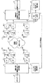
図1は、通常の階層的空間−時間構造の検波器を有するMIMO無線通信システムの構成図である。 FIG. 1 is a configuration diagram of a MIMO wireless communication system having a normal hierarchical space-time structure detector.
図1に示すように、V−BLASTの構造の検波器を有するMIMOシステムにおいて、各送信アンテナ13A、13B、…、13Nから送信される信号ベクトルx=[x0,x1,A,xM−1]、と各受信アンテナ15A、15B、…、15Mに該当する受信信号ベクトルy=[y0,y1,A,yN−1] を定義する。ここで、MとNは各々送信、受信アンテナの個数を示し、N≧Mの条件を満足しなければならない。この場合、受信信号ベクトルは下記の[数式6]に表現される。
y=Hx+v ・・・数式6
As shown in FIG. 1, in a MIMO system having a detector having a V-BLAST structure, signal vectors x = [x 0 , x 1 , A, x M transmitted from the transmission antennas 13A, 13B,. −1 ] and the received signal vectors y = [y 0 , y 1 , A, y N−1 ] corresponding to the receiving antennas 15A, 15B,. Here, M and N indicate the number of transmitting and receiving antennas, respectively, and the condition of N ≧ M must be satisfied. In this case, the received signal vector is expressed by the following [Equation 6].
y = Hx +
前記[数式6]において、HはM×Nチャネル行列、チャネル行列Hのn番目の行、m番目の列の元素、hn、mはm番目の送信アンテナとn番目の受信アンテナとの間の平坦フェーディング・チャネル(flat fading channel)値を各々示す。一方、vは平均が0であり、E[vvH]=σ2Iの共分散行列を有するN×1の白色雑音ベクトル(White Noise Vector)であり、IはN×N単位行列である。 In [Formula 6], H is an M × N channel matrix, the nth row and mth column element of the channel matrix H, and hn and m are between the mth transmitting antenna and the nth receiving antenna. The flat fading channel values are shown respectively. On the other hand, v is an N × 1 white noise vector having an average of 0 and having a covariance matrix of E [vv H ] = σ 2 I, and I is an N × N unit matrix.
y(受信信号ベクトル)からx(送信信号ベクトル)を復元するため、V−BLASTの検波方法を使用し、ナリング・ベクトルはゼロ・フォーシング(Zero-Forcing)方法で決定する場合、k番目の階層(k番目の送信アンテナの信号)に対するナリング・ベクトルは下記の[数式7]のように定義される。 In order to restore x (transmission signal vector) from y (reception signal vector), if the V-BLAST detection method is used and the nulling vector is determined by the zero-forcing method, the k th The nulling vector for the layer (the signal of the kth transmitting antenna) is defined as in [Equation 7] below.
前記[数式7]において、(H)lは行列Hのl(エル)番目の列であり、 In [Formula 7], (H) l is the l th column of the matrix H;
![]()
![]()
はチャネル行列の可逆行列(Pseudo-Inverse Matrix)H+のk番目の行である。Wkの値を判断して検波順序を決定するが、従来の技術のV−BLASTの検波方法では‖Wk‖が小さいものから検波する順序に従った。一方、Zkはk番目の階層に対する決定統計量(Decision Statistic)であり、下記の[数式8]で表現される。 Is the k-th row of a channel matrix reversible matrix (Pseudo-Inverse Matrix) H + . The order of detection is determined by judging the value of W k , but in the conventional V-BLAST detection method, the order of detection from the smallest ‖ W kに 従 is followed. On the other hand, Z k is a decision statistic for the k-th hierarchy, and is expressed by the following [Equation 8].
![]()
![]()
前記[数式8]において、kはk={1、2、…、M}である。前記決定統計量(Zk)を有し、信号決定をした後にはチャネル行列Hと受信信号ベクトルyで決定された信号の影響を除去する。すなわち、既存のHからk番目の列を全て0にして新しいチャネル行列Hを生成する。一方、新しい受信信号ベクトル は前記[数式6]によって決定する。 In [Formula 8], k is k = {1, 2,..., M}. After determining the signal having the determination statistic (Z k ), the influence of the signal determined by the channel matrix H and the received signal vector y is removed. That is, a new channel matrix H is generated by setting all kth columns from the existing H to 0. On the other hand, a new received signal vector is determined by the above [Formula 6].
![]()
![]()
前記[数式9]において、 In [Formula 9],
![]()
![]()
はZkの決定結果である。前記新しいチャネル行列Hと受信信号ベクトルy’を利用してナリング・ベクトルを求める過程から全ての送信信号を検波するまで、前記[数式6]ないし[数式9]の過程を繰り返すことになるが、この過程が従来の技術によるV−BLASTの検波過程である。検波順序はナリング・ベクトルのノーム(Norm)の大きさによって決定される。 Is the determination result of Z k . From the process of obtaining a nulling vector using the new channel matrix H and the received signal vector y ′ to the detection of all transmission signals, the processes of [Equation 6] to [Equation 9] are repeated. This process is a conventional V-BLAST detection process. The detection order is determined by the magnitude of the norm of the nulling vector.
決定統計量の信号対雑音比Pkを求めるため、前記[数式7]を利用すると、下記の[数式10]のように表現できる。 In order to obtain the signal-to-noise ratio P k of the decision statistic, the above [Equation 7] is used and can be expressed as [Equation 10] below.
前記[数式10]において、E{}は、期待値(Expectation Value)関数であり、‖Wk‖-2 は、等価チャネル利得(Equivalent Channel Gain)である。したがって、‖Wk‖-2 が小さいほどチャネルの状態が良いといえる。固定変復調方法を使用するMIMOシステムのためのV−BLAST方法は、チャネル状態の良い階層を先に検波し、チャネル状態の悪い階層は既に検波が終了した信号の影響を除去した後に検波することによって、全ての階層が全体的に良い性能を表すようにする方法である。しかし、適応変復調方法では、前記固定変復調方法とは異なって良い階層を後に検波して性能をより良くし、悪い階層に対しては情報を伝送しないか、少ない量の情報のみを伝送して性能を向上させる方法である。したがって、適応変復調方法においては、本発明で提示するように既存のV−BLASTのような検波順序の逆順に検波しないと性能を向上させることができない。
In [Formula 10], E {} is an expected value function, and ‖W k ‖ -2 is an equivalent channel gain. Therefore, it can be said that the smaller the ‖W k ‖- 2, the better the channel state. The V-BLAST method for a MIMO system using a fixed modulation / demodulation method detects a layer having a good channel state first, and detects a layer having a bad channel state after removing the influence of a signal that has already been detected. This is a method in which all the hierarchies express overall good performance. However, in the adaptive modulation / demodulation method, unlike the fixed modulation / demodulation method, the performance is improved by detecting a good layer later, and information is not transmitted to the bad layer or only a small amount of information is transmitted. It is a method to improve. Therefore, in the adaptive modulation / demodulation method, as shown in the present invention, the performance cannot be improved unless detection is performed in the reverse order of the detection order as in the existing V-BLAST.
まず、図5を参照しながら本発明に係る階層的空間−時間構造(V−BLASI TYPE)の検波器を有する多重入出力(MIMO)無線通信システムにおける適応変復調装置について述べる。 First, an adaptive modulation / demodulation apparatus in a multiple input / output (MIMO) wireless communication system having a hierarchical space-time structure (V-BLASI TYPE) detector according to the present invention will be described with reference to FIG.
図5に示すように、階層的空間−時間構造(V−BLASI TYPE)の検波器を有する多重入出力(MIMO)無線通信システムは、階層的空間−時間構造に基づいた適応変調部52、M個の送信アンテナ53−1、53−2〜53−M、ビット及び電力割り当て情報算出部54、周波数−非選択的フェーディングMIMOチャネル55、N個の受信アンテナ56−1、56−2〜56−N、階層的空間−時間構造に基づいた検波及び適応復調部57、MIMOチャネル推定部58、ビット割り当て情報算出部59から構成されている。
As shown in FIG. 5, a multiple input / output (MIMO) wireless communication system having a hierarchical space-time structure (V-BLASI TYPE) detector includes an
階層的空間−時間構造の検波器を有する多重入出力(MIMO)システムに適用される適応変復調装置を述べると、送信端では受信端からフィードバックされたMIMOチャネル情報に基づいてV−BLAST(Vertical-Bell Laboratories Space Time)の逆順に等価チャネル利得を決定し、この等価チャネル利得を利用して各送信アンテナに伝送されるビット数と送信電力とを決定するためのビット及び電力割り当て情報算出部54と、ビット及び電力割り当て情報算出部54で決定されたビット及び電力割り当て情報を利用して、各階層(送信アンテナ)別に異なる変調方法で変調し送信電力を調節し、適応変調された信号を各送信アンテナ53−1〜53−Mを介して伝送する階層的空間−時間構造に基づいた適応変調部52を含み、受信端では、各受信アンテナ56−1〜56−Nを介して各々受信される信号からMIMOチャネルを推定するためのMIMOチャネル推定部58と、MIMOチャネル推定部58からのMIMOチャネル情報に基づいてV−BLAST(Vertical-Bell Laboratories Space Time)の逆順に等価チャネル利得を決定し、この等価チャネル利得を利用して各受信アンテナ56−1〜56−Nに受信されたビット数と受信電力とを決定するためのビット及び電力割り当て情報算出部59と、ビット及び電力割り当て情報算出部59で決定されたビット及び電力割り当て情報とMIMOチャネル情報とに基づいて、各階層(受信アンテナ)別に受信される信号の受信電力を調節して、互いに異なる復調方法で復調するための階層的空間−時間構造に基づいた検波及び適応復調部57を含む。
An adaptive modulation / demodulation apparatus applied to a multiple input / output (MIMO) system having a hierarchical space-time structure detector will be described. Based on MIMO channel information fed back from a receiving end, a transmitting end uses V-BLAST (Vertical- Bell Laboratories Space Time), and a bit and power allocation
本発明に係る階層的空間−時間構造の検波器を有する多重入出力(MIMO)システムに適用される適応変復調装置の動作を述べると以下の通りである。 The operation of the adaptive modulation / demodulation apparatus applied to a multiple input / output (MIMO) system having a hierarchical space-time structure detector according to the present invention will be described as follows.
送信データ51は、送信端から伝送しようとするデータであって、スクランブリング(Scrambling)、コーディング(Coding)、インターリビング(Interleaving)などからなるデータなどであり、外部からこのようなデータを入力された階層的空間−時間構造に基づいた適応変調部52では、ビット及び電力割り当て情報を利用して各階層別に異なる変調方法で変調し送信電力を調節する機能をする。
The transmission data 51 is data to be transmitted from the transmission end, and is data including scrambling, coding, interleaving, and the like. The
また、このように適応変調された信号がM個の送信アンテナ53−1〜53−Mを介して伝送されると、ビット及び電力割り当て情報算出部54は、受信端からフィードバックされたMIMOチャネル情報を利用して、グリーディ・アルゴリズムを通して各送信アンテナ53−1〜53−Mに伝送されるビット数と送信電力とを決定する。
Further, when the adaptively modulated signal is transmitted through the M transmitting antennas 53-1 to 53-M, the bit and power allocation
このようにM個の送信アンテナ53−1〜53−Mから伝送された信号が周波数−非選択的フェーディングMIMOチャネル55を経てN個の受信アンテナ56−1〜56−Nに受信される。そして階層的空間−時間構造に基づいた検波及び適応復調部57では、受信された信号をMIMOチャネル推定部58のチャネル推定結果とビット割り当て情報算出部59のビット割り当て情報とを利用してV−BLASTの逆順に復調し、復調されたデータを出力する。
Thus, the signals transmitted from the M transmission antennas 53-1 to 53-M are received by the N reception antennas 56-1 to 56-N via the frequency-nonselective
図2は、本発明に利用される階層的空間−時間構造において、ナリング順序によって等価チャネル利得が変化することを示す一実施例の説明図である。 FIG. 2 is an explanatory diagram of an embodiment showing that the equivalent channel gain varies depending on the nulling order in the hierarchical space-time structure used in the present invention.
図2に示すように、同じチャネル行列を利用するとしてもV−BLAST順序、任意の順序、そしてV−BLAST逆順のうち、どの順序によって検波したかによって等価チャネル利得が変わる。したがって、前記のようにV−BLASTの順序を使用して検波する場合には、等価チャネル利得の偏差が小さいため全体利得を分ける結果が生じ、V−BLASTの逆順に検波する場合には偏差がより大きくなる結果が生じる。 As shown in FIG. 2, even if the same channel matrix is used, the equivalent channel gain varies depending on the order of detection in the V-BLAST order, an arbitrary order, and the V-BLAST reverse order. Therefore, when the detection is performed using the V-BLAST order as described above, the result of dividing the overall gain occurs because the deviation of the equivalent channel gain is small, and when the detection is performed in the reverse order of V-BLAST, the deviation is large. A bigger result is produced.
以下、本発明に係るV−BLAST検波方法の逆順に等価チャネル利得を決定する方法を詳細に説明する。 Hereinafter, a method for determining the equivalent channel gain in the reverse order of the V-BLAST detection method according to the present invention will be described in detail.
図3は、本発明に係る適応変復調方法のうち、V−BLASTの逆順に等価チャネル利得を決定する過程に対する一実施例の詳細フローチャートである。 FIG. 3 is a detailed flowchart of an embodiment of the process of determining the equivalent channel gain in the reverse order of V-BLAST in the adaptive modulation / demodulation method according to the present invention.
図3に示すように、等価チャネル利得を決定するためには、先に検波順序を決定しなければならないため、アンテナ・インデックスの集合S(S={1、2、…、M})を定義する(31)。また、M×Nチャネル行列 の可逆行列を算出する(32)。また、送信信号ベクトルxを求めるため、全てのk(k∈S)番目の階層(k番目の送信アンテナの信号)に対するナリング・ベクトル As shown in FIG. 3, in order to determine the equivalent channel gain, the detection order must first be determined, and therefore a set S (S = {1, 2,..., M}) of antenna indexes is defined. (31). Further, a reversible matrix of M × N channel matrix is calculated (32). Further, in order to obtain a transmission signal vector x, a nulling vector for all k (kεS) layers (signals of the kth transmission antenna)
![]()
![]()
を求めなければならないが、これは前記[数式7]で求めることができる(33)。 Must be obtained, which can be obtained by the above [Equation 7] (33).
以後、ナリングする階層を決定するため、ナリング・ベクトルのノームの自乗値を算出し、このうち最も大きい値を有した Thereafter, in order to determine the hierarchy to be nulled, the square value of the nom of the nulling vector was calculated and had the largest value among them.
![]()
![]()
階層を選択する(34)。そして、選択された A hierarchy is selected (34). And selected
![]()
![]()
階層に該当するチャネル行列Hの列ベクトルを0ベクトルに変形し、集合Sから The column vector of the channel matrix H corresponding to the hierarchy is transformed into a 0 vector, and from the set S
![]()
![]()
値を除去する(35)。新しく変形された集合Sとチャネル行列Hに対して前記の過程をM回、繰り返す。 The value is removed (35). The above process is repeated M times for the newly modified set S and channel matrix H.
このように選択された階層順序が検波順序となり、選択された階層に対するナリング・ベクトルのノームの自乗値の逆数が等価チャネル利得となる。こういう順で求めた等価チャネル利得を前記グリーディ・アルゴリズムの副搬送波チャネル利得||hn|2|に代わる値として使用し、各階層(送信アンテナ)から伝送する情報ビット数とこれに該当する送信電力とを算出できる。 The hierarchical order selected in this way is the detection order, and the inverse of the squared nom of the nulling vector for the selected hierarchy is the equivalent channel gain. The equivalent channel gain obtained in this order is used as a value to replace the subcarrier channel gain || h n | 2 | of the greedy algorithm, and the number of information bits transmitted from each layer (transmission antenna) and the transmission corresponding thereto The power can be calculated.
図4は、本発明に係る適応変復調方法のうち、グリーディ・アルゴリズムによって等価チャネル利得を利用して、各送信アンテナに対する伝送ビット数と送信電力とを決定する過程に対する一実施例の詳細フローチャートである。 FIG. 4 is a detailed flowchart of an embodiment of the process of determining the number of transmission bits and the transmission power for each transmission antenna using the equivalent channel gain according to the greedy algorithm in the adaptive modulation / demodulation method according to the present invention. .
図4に示すように、まず各階層(各送信アンテナ)から伝送するビット数を全部0と初期化する(41)。そして、前記[数式2]のようにΔB値を定義し、各階層の等価チャネル利得を利用して各階層で付加的なΔBビット値を所望のビット・エラー確率で得るための送信電力を算出する。この内、最も小さい電力を必要とする階層にΔB値を載せる。上記の過程をシステムで決めておいた総ビット数を割り当てるまで行う。各階層を通して送信するビット数が決定されると、前記[数式1]を通して各階層の送信電力を算出できる。 As shown in FIG. 4, first, the number of bits transmitted from each layer (each transmitting antenna) is initialized to 0 (41). Then, ΔB value is defined as in [Formula 2], and transmission power for obtaining an additional ΔB bit value at each layer with a desired bit error probability is calculated using the equivalent channel gain of each layer. To do. Among these, the ΔB value is placed on the layer that requires the least power. The above process is repeated until the total number of bits determined by the system is allocated. When the number of bits to be transmitted through each layer is determined, the transmission power of each layer can be calculated through [Formula 1].
図6は、本発明の実施例によって階層的空間−時間構造の検波器を有する多重入出力(MIMO)無線通信システムにおける適応変復調方式の性能を示す説明図であって、本発明に係る方法と従来の技術に係る方法の性能を確認するため、既存の方法と比較する性能シミュレーション実験を行った結果を示す。 FIG. 6 is an explanatory diagram illustrating the performance of an adaptive modulation / demodulation scheme in a multiple input / output (MIMO) wireless communication system having a hierarchical space-time detector according to an embodiment of the present invention. In order to confirm the performance of the method according to the prior art, the result of a performance simulation experiment compared with the existing method is shown.
シミュレーション実験において、送信アンテナと受信アンテナの個数は各々4個とし、各送受信アンテナに該当するチャネルは0平均を有する複素ガウス確率変数(Complex Gaussian Random Variable)とした。また、特定チャネル行列の影響によって性能が制限されることを防止するため、1000回以上の統計的チャネルを生成してシミュレーション実験を行った。また、全ての送信アンテナから一定間隔で伝送されるR(情報ビットの数)は8に固定した。 In the simulation experiment, the number of transmitting antennas and the number of receiving antennas was four, and the channel corresponding to each transmitting / receiving antenna was a complex Gaussian random variable having zero average. Further, in order to prevent the performance from being limited by the influence of the specific channel matrix, a simulation experiment was performed by generating a statistical channel of 1000 times or more. Further, R (number of information bits) transmitted from all the transmitting antennas at a fixed interval was fixed to 8.
変調方法は、QPSKと16−QAMを使用し、D={0、2、4}であるため、ΔBは2である。 The modulation method uses QPSK and 16-QAM, and D = {0, 2, 4}, so ΔB is 2.
適応変調MIMOシステムにおいて最適解と知られている特異値分解(SVD:Singular Value Decomposition)を利用してグリーディ・アルゴリズムを適用した方法をG.G.Raleighなどが提案している(例えば、特許文献6参照)が、これは構造が非常に複雑で実際具現がほとんど不可能であるという問題点がある。そこで、本シミュレーション実験ではこの方法による性能をシステム性能の下方境界(Lower Bound)に利用した。 A method in which a greedy algorithm is applied using Singular Value Decomposition (SVD), which is known as an optimal solution in an adaptive modulation MIMO system, is described in G. G. Raleigh and the like have proposed (for example, see Patent Document 6), but this has a problem that the structure is very complicated and practical implementation is almost impossible. Therefore, in this simulation experiment, the performance of this method was used for the lower bound of the system performance.
図6において、SVDはG.G.Raleighが提案した特異値分解を利用した方法による結果であり、BLASTはKa−Wai Ngが提案したV−BLASTの検波方法の順序を、BLASTは、各々任意順序に等価チャネル利得を決定する方法による結果を示す。BLAST(本発明)が本発明で提案したV−BLAST検波方法の逆順に従って等価チャネル利得を決定する方法による結果である。 In FIG. G. This is a result of a method using singular value decomposition proposed by Raleigh, where BLAST is an order of V-BLAST detection methods proposed by Ka-Wai Ng, and BLAST is a method of determining an equivalent channel gain in an arbitrary order. Results are shown. BLAST (present invention) is the result of the method of determining the equivalent channel gain according to the reverse order of the V-BLAST detection method proposed in the present invention.
図6に示すように、本発明に係る方法はKa−Wai Ngの方法よりは0.7dB程度の性能利得を有し、最適解といえるG.G.Raleighの特異値分解方法よりは約1dB程度の性能劣化がある。 As shown in FIG. 6, the method according to the present invention has a performance gain of about 0.7 dB compared with the Ka-Wai Ng method, and can be said to be an optimal solution. G. There is a performance degradation of about 1 dB compared to the Raleigh singular value decomposition method.
図7は、本発明に係る階層的空間−時間構造の検波器を有する多重入出力直交周波数分割多重化(OFDM)無線通信システムにおける適応変復調装置を示す一実施例の構成図である。 FIG. 7 is a block diagram of an embodiment showing an adaptive modulation / demodulation apparatus in a multiple input / output orthogonal frequency division multiplexing (OFDM) wireless communication system having a hierarchical space-time structure detector according to the present invention.
図7に示すように、本発明に係る適応変調MIMOシステムは、MIMO OFDMシステムに拡張できる。これはMIMOシステムにおけるチャネル行列 は、MIMO−OFDMシステムにおける送信部と受信部の各副搬送波との間のチャネル行列と対応するためである。前記MIMO OFDMに適用できる方法には以下の2種類がある。 As shown in FIG. 7, the adaptive modulation MIMO system according to the present invention can be extended to a MIMO OFDM system. This is because the channel matrix in the MIMO system corresponds to the channel matrix between the subcarriers of the transmitter and the receiver in the MIMO-OFDM system. There are the following two methods applicable to the MIMO OFDM.
第一の方法は、全副搬送波(Nc)と全階層(M)に対して適応変調を適用する方法である。まず、各副搬送波別に各々の送信アンテナ階層に対して等価チャネル利得を求める。次いで、前記図3に示した方法で各副搬送波別に送信アンテナ階層の個数だけの等価チャネル利得を求める。そうすると、全副搬送波に対して副搬送波の数(Nc)×送信アンテナ階層の数(M)だけの等価チャネル利得が得られる。このように得られたNc×M個の等価チャネル利得を有して前記図4に記載されたグリーディ・アルゴリズムによってNc×R個の情報ビットと送信電力とを割り当てる方法である。 The first method is a method of applying adaptive modulation to all subcarriers (Nc) and all layers (M). First, an equivalent channel gain is obtained for each transmission antenna layer for each subcarrier. Next, the equivalent channel gain corresponding to the number of transmission antenna layers is obtained for each subcarrier by the method shown in FIG. Then, an equivalent channel gain corresponding to the number of subcarriers (N c ) × the number of transmission antenna layers (M) is obtained for all subcarriers. This is a method of assigning N c × R information bits and transmission power using the greedy algorithm described in FIG. 4 with N c × M equivalent channel gains obtained in this way.
したがって、MIMO−OFDM送信部に総データ・レート(data rate)が決められている場合、総Nc×M個の等価チャネルにデータ・レートを割り当てるためには、前記図4に示したグリーディ・アルゴリズムを通してNc×M個の等価チャネル利得を利用して決定できるようになる。この場合、図4のM値はNc×Mとなる。しかし、前記方法の場合、グリーディ・アルゴリズムで比較対象及び繰り返し回数が増加して、システムを具現する時に、非常に複雑となるという短所がある。 Therefore, when the total data rate is determined in the MIMO-OFDM transmitter, in order to assign the data rate to the total N c × M equivalent channels, the greedy signal shown in FIG. Through the algorithm, it can be determined using N c × M equivalent channel gains. In this case, the M value in FIG. 4 is N c × M. However, in the case of the above method, the comparison target and the number of repetitions are increased by the greedy algorithm, so that it is very complicated when the system is implemented.
第2の方法は、副搬送波別に各々適応変調をする方法である。すなわち、MIMO OFDMシステムに総データ・レートが決められており、各副搬送波別に割り当てられているデータ・レートが全て同一であると、各々の副搬送波別に等価チャネル利得を求めてデータ・レートを割り当てなければならない。この場合等価チャネル利得は、各副搬送波別に総M個となり、M個の副搬送波別に前記図4に示したグリーディ・アルゴリズムを利用してデータ・レートを割り当てる。したがって、全体的にNc回のグリーディ・アルゴリズムを行うが、比較する個数がM個であり、繰り返し回数も低減する。このような方法は、前記第1の方法に比べて簡単に具現できるという長所はあるが、前記第1の方法よりは性能が低下するという短所がある。 The second method is a method of performing adaptive modulation for each subcarrier. That is, if the total data rate is determined for the MIMO OFDM system and the data rates assigned to each subcarrier are all the same, the data rate is assigned by obtaining the equivalent channel gain for each subcarrier. There must be. In this case, the total equivalent channel gain is M for each subcarrier, and the data rate is assigned to each of the M subcarriers using the greedy algorithm shown in FIG. Therefore, although Nc greedy algorithms are performed as a whole, the number of comparisons is M, and the number of iterations is also reduced. Such a method has an advantage that it can be easily implemented as compared with the first method, but has a disadvantage that the performance is lower than that of the first method.
ビット及び電力割り当て情報算出部73は、MIMOチャネル推定部82から伝送した各副搬送波に対するチャネル行列Hを使用してデータ・レートを割り当て、割り当てられたデータ・レートと各副搬送波に対する等価チャネル利得を利用して、各副搬送波に対する各送信アンテナ76−1 to 76−Mにおける電力を割り当てる。 The bit and power allocation information calculation unit 73 allocates a data rate using the channel matrix H for each subcarrier transmitted from the MIMO channel estimation unit 82, and calculates the allocated data rate and the equivalent channel gain for each subcarrier. Utilizing this, power is allocated at each transmit antenna 76-1 to 76-M for each subcarrier.
階層的空間−時間構造に基づいた適応変調部72は、ビット及び電力割り当て情報算出部73から各副搬送波別に各送信アンテナ76−1 to 76−Mに割り当てられたビットと電力とを利用して、実際伝送するための変調作業を行う。
The
MIMO OFDMで受信された信号を復調するためには、各副搬送波別のチャネル行列と送信部から適応変調を通して各副搬送波別に各アンテナを介して伝送されたビットと電力を分からなければならない。したがって、受信側に存在するMIMOチャネル推定部82は、各副搬送波別にチャネル行列Hを推定し、ビット割り当て情報算出部83は、前記チャネル行列を利用して送信側で行なった等価チャネル利得を求める過程及びグリーディ・アルゴリズムにより各副搬送波別に各受信アンテナ80A〜80Nに割り当てられたビット及び電力を求める過程を行う。
In order to demodulate a signal received by MIMO OFDM, it is necessary to know the channel matrix for each subcarrier and the bit and power transmitted via each antenna for each subcarrier through adaptive modulation from the transmitter. Therefore, the MIMO channel estimation unit 82 existing on the reception side estimates the channel matrix H for each subcarrier, and the bit allocation
また、空間−時間構造に基づいた検波及び適応復調部81では、算出されたビットと電力情報とを利用して伝送された信号を復調する。 The detection and adaptive demodulation unit 81 based on the space-time structure demodulates the transmitted signal using the calculated bits and power information.
図8は、本発明の実施例によって階層的空間−時間構造の検波器を有する多重入出力直交周波数分割多重化(OFDM)無線通信システムにおける適応変復調方式の性能を示す説明図である。 FIG. 8 is an explanatory diagram illustrating the performance of an adaptive modulation / demodulation scheme in a multiple input / output orthogonal frequency division multiplexing (OFDM) wireless communication system having a hierarchical space-time detector according to an embodiment of the present invention.
図8に示すように、シミュレーション実験結果は、前記図6に示した単一搬送波MIMOシステムで実験した結果が大体維持されることが確認できる。本シミュレーション実験結果は、全副搬送波と階層に対してグリーディ・アルゴリズムを適用して適応変調する方法で実験した結果を示すものである。本シミュレーション実験において送受信アンテナは各々4個であり、OFDMにおいて全体副搬送波の個数は64であり、循環前置(CP:Cyclic Prefix)の個数は16とした。また、8タブを有する指数的に減少する準静的フェーディング・チャネル(Exponentially Decaying Quasi-Static Fading Channel)を使用した。 As shown in FIG. 8, it can be confirmed that the result of the simulation experiment is substantially maintained as a result of the experiment with the single carrier MIMO system shown in FIG. This simulation experimental result shows a result of an experiment by a method of adaptive modulation by applying a greedy algorithm to all subcarriers and layers. In this simulation experiment, the number of transmitting / receiving antennas is four, the number of total subcarriers in OFDM is 64, and the number of cyclic prefixes (CP) is 16. An exponentially decreasing quasi-static fading channel with 8 tabs was used.
上述したような本発明の方法は、プログラムで具現されてコンピュータで読み出すことのできる形態に記録媒体(CD ROM、RAM、ROM、フロッピー(登録商標)ディスク、ハードディスク、光磁気ディスクなど)に格納され得る。このような過程は、本発明が属する技術分野における通常の知識を有する者が容易に実施できるので、これ以上詳細に説明しない。 The method of the present invention as described above is stored in a recording medium (a CD ROM, a RAM, a ROM, a floppy (registered trademark) disk, a hard disk, a magneto-optical disk, etc.) in a form that can be implemented by a program and read by a computer. obtain. Such a process can be easily carried out by a person having ordinary knowledge in the technical field to which the present invention belongs and will not be described in further detail.
なお、本発明は、上記の実施例として開示した範囲に限定されるものではない。本発明に係る技術的思想から逸脱しない範囲内で多くの改良、変更が可能であり、それらも本発明の技術的範囲に属する。 In addition, this invention is not limited to the range disclosed as said Example. Many improvements and modifications can be made without departing from the technical idea of the present invention, and these also belong to the technical scope of the present invention.
11、51、71 送信するデータ
12、52、72 階層的空間−時間構造に基づく適応変調部
13A〜13M、53−1〜53−M、76−1 to 76−M 送信アンテナ
14、55、77 周波数非選択的フェーディング多重入出力チャネル
15A〜15M、56−1〜56M、78A〜78M 受信アンテナ
16、57、81 階層的空間−時間構造に基づく適応復調部
54、73 ビット及び電力割り当て情報算出部
58、82 多重入出力チャネル推定部
74 逆フーリエ変換器
75、79 循環前置付加装置
84 復調されたデータ
11, 51, 71 Data to be transmitted 12, 52, 72 Adaptive modulation units 13A to 13M, 53-1 to 53-M, 76-1 to 76-M based on a hierarchical space-time structure Transmit
Claims (20)
受信端からフィードバックされたMIMOチャネル情報に基づいて、V−BLAST(Vertical-Bell Laboratories Space Time)の逆順に等価チャネル利得を決定し、当該等価チャネル利得を利用して各送信アンテナに伝送するビット数と送信電力とを決定するためのビット及び電力割り当て情報算出手段と、
前記ビット及び電力割り当て情報算出手段で決定されたビット及び電力割り当て情報を利用して各階層(送信アンテナ)別に異なる変調方法で変調し送信電力を調節して、適応変調された信号を、各送信アンテナを介して伝送する適応変調手段と
を含むことを特徴とする階層的空間−時間構造の検波器を有する多重入出力システムに適用される適応変調装置。 In an adaptive modulation apparatus in a multiple input / output (MIMO) system that uses multiple antennas at the transmitting and receiving ends,
Based on MIMO channel information fed back from the receiving end, the equivalent channel gain is determined in the reverse order of V-BLAST (Vertical-Bell Laboratories Space Time), and the number of bits transmitted to each transmitting antenna using the equivalent channel gain And bit and power allocation information calculation means for determining transmission power,
Using the bit and power allocation information determined by the bit and power allocation information calculation means, modulation is performed by a different modulation method for each layer (transmission antenna) and transmission power is adjusted, and an adaptively modulated signal is transmitted for each transmission. An adaptive modulation device applied to a multiple input / output system having a hierarchical space-time structure detector, comprising: adaptive modulation means for transmitting via an antenna.
各受信アンテナを介して各々受信される信号からMIMOチャネルを推定するためのMIMOチャネル推定手段と、
前記MIMOチャネル推定手段におけるMIMOチャネル情報に基づいて、V−BLAST(Vertical-Bell Laboratories Space Time)の逆順に等価チャネル利得を決定し、当該等価チャネル利得を利用して各受信アンテナに受信されたビット数と受信電力とを決定するためのビット及び電力割り当て情報算出手段と、
前記ビット及び電力割り当て情報算出手段で決定されたビット及び電力割り当て情報と前記MIMOチャネル情報とに基づいて、各階層(受信アンテナ)別に受信される信号の受信電力を調節して、互いに異なる復調方法で復調するための適応変調手段と
を含むことを特徴とする階層的空間−時間構造の検波器を有する多重入出力システムに適用される適応復調装置。 In an adaptive demodulator in a multiple input / output (MIMO) system using multiple antennas at the transmitting and receiving ends,
MIMO channel estimation means for estimating a MIMO channel from a signal received via each receiving antenna;
Based on the MIMO channel information in the MIMO channel estimation means, an equivalent channel gain is determined in the reverse order of V-BLAST (Vertical-Bell Laboratories Space Time), and the bit received by each receiving antenna using the equivalent channel gain Bit and power allocation information calculation means for determining the number and received power;
Different demodulation methods by adjusting received power of signals received for each layer (receiving antenna) based on the bit and power allocation information determined by the bit and power allocation information calculation means and the MIMO channel information An adaptive demodulator applied to a multiple input / output system having a hierarchical space-time detector.
V−BLAST(Vertical-Bell Laboratories Space Time)の逆順に等価チャネル利得を決定し、当該等価チャネル利得を利用して各送信アンテナに伝送するビット数と送信電力とを決定した後、適応変調して送信するための適応変調手段と、
各受信アンテナを介して受信される信号をV−BLAST(Vertical-Bell Laboratories Space Time)の逆順に検波及び適応復調するための適応復調手段と
を含むことを特徴とする階層的空間−時間構造の検波器を有する多重入出力システムに適用される適応変復調装置。 In an adaptive modulation / demodulation apparatus in a multiple input / output (MIMO) system that uses multiple antennas at the transmission and reception terminals
The equivalent channel gain is determined in the reverse order of V-BLAST (Vertical-Bell Laboratories Space Time), the number of bits transmitted to each transmitting antenna and the transmission power are determined using the equivalent channel gain, and then adaptive modulation is performed. Adaptive modulation means for transmitting;
An adaptive demodulation means for detecting and adaptively demodulating a signal received via each receiving antenna in reverse order of V-BLAST (Vertical-Bell Laboratories Space Time). An adaptive modulation / demodulation device applied to a multiple input / output system having a detector.
受信端からフィードバックされた情報に基づいて、送信端でV−BLASTの逆順に等価チャネル利得を決定する第1ステップと、
前記送信端において、前記等価チャネル利得をグリーディ・アルゴリズムの副搬送波チャネル利得に代わる値として利用して、各階層(送信アンテナ)から伝送する情報ビットの数とこれに該当する送信電力とを決定して適応変調する第2ステップと
を含むことを特徴とする多重入出力(MIMO)システムに適用される適応変調方法。 In an adaptive modulation method in a multiple input / output (MIMO) system using multiple antennas at the transmitting and receiving ends,
A first step of determining an equivalent channel gain in the reverse order of V-BLAST at the transmitting end based on information fed back from the receiving end;
At the transmitting end, the number of information bits transmitted from each layer (transmitting antenna) and the corresponding transmission power are determined using the equivalent channel gain as a value to replace the subcarrier channel gain of the greedy algorithm. And an adaptive modulation method applied to a multiple input / output (MIMO) system.
アンテナ・インデックスの集合を初期化する第3ステップと、
等価チャネル利得が小さい階層からナリングし、その結果でチャネル行列及び前記アンテナ・インデックスの集合を修正する第4ステップと、
アンテナの数だけ前記第4ステップを繰り返し行なう第5ステップと、
前記第5ステップの結果を通して各アンテナ階層の等価チャネル利得を決定する第6ステップと
を含むことを特徴とする請求項10または11に記載の多重入出力(MIMO)システムに適用される適応変調方法。 The first step includes
A third step of initializing a set of antenna indices;
A fourth step of nulling from a hierarchy where the equivalent channel gain is small, and thereby modifying the set of channel matrix and said antenna index;
A fifth step of repeating the fourth step by the number of antennas;
The adaptive modulation method applied to a multiple input / output (MIMO) system according to claim 10 or 11, further comprising: a sixth step of determining an equivalent channel gain of each antenna layer through a result of the fifth step. .
チャネル行列の可逆行列を算出する第7ステップと、
ナリングする階層を決定するため、ナリング・ベクトルのノーム(norm)の自乗値を算出する第8ステップと、
前記第8ステップの値の内、最大値を有する階層を選択する第9ステップと、
前記第9ステップで選択された階層をナリングし、前記アンテナ・インデックスの集合から選択された階層を除去する第10ステップと
を含むことを特徴とする請求項12に記載の多重入出力(MIMO)システムに適用される適応変調方法。 The fourth step includes
A seventh step of calculating a reversible matrix of the channel matrix;
An eighth step of calculating a square of the norm of the nulling vector to determine the hierarchy to be nulled;
A ninth step of selecting a hierarchy having the maximum value among the values of the eighth step;
13. The multiple input / output (MIMO) according to claim 12, comprising: nulling the hierarchy selected in the ninth step and removing the selected hierarchy from the antenna index set. Adaptive modulation method applied to the system.
アンテナ・インデックスの集合を初期化する第3ステップと、
等価チャネル利得が小さい階層からナリングし、その結果でチャネル行列及び前記アンテナ・インデックスの集合を修正する第4ステップと、
アンテナの数だけ前記第4ステップを繰り返し行なう第5ステップと、
前記第5ステップの結果を通して各アンテナ階層の等価チャネル利得を決定する第6ステップと、
各々の副搬送波に対して前記第1ステップから前記第4ステップまでの過程を繰り返し行なって、等価チャネル利得を決定する第7ステップと
を含むことを特徴とする請求項10または11に記載の多重入出力(MIMO)システムに適用される適応変調方法。 The first step includes
A third step of initializing a set of antenna indices;
A fourth step of nulling from a hierarchy where the equivalent channel gain is small, and thereby modifying the set of channel matrix and said antenna index;
A fifth step of repeating the fourth step by the number of antennas;
A sixth step of determining an equivalent channel gain of each antenna layer through the result of the fifth step;
The multiplex according to claim 10 or 11, further comprising: a seventh step of determining an equivalent channel gain by repeatedly performing the process from the first step to the fourth step for each subcarrier. An adaptive modulation method applied to an input / output (MIMO) system.
多重入出力直交周波数分割多重化(MIMO−OFDM)システムにおいて、システムの総データ・レート(date rate)が決められており、各副搬送波別に割り当てられているデータ・レートが同一に指定された場合において、
一つの副搬送波に対して、アンテナ・インデックスの集合を初期化する第3ステップと、
前記一つの副搬送波に対して、等価チャネル利得が小さい階層からナリングし、その結果でチャネル行列及び前記アンテナ・インデックスの集合を修正する第4ステップと、
前記一つの副搬送波に対して、アンテナの数だけ前記第4ステップを繰り返し行なう第5ステップと、
前記一つの副搬送波に対して、前記第5ステップの結果を通して各アンテナ階層の等価チャネル利得を決定する第6ステップと
を含むことを特徴とする請求項10または11に記載の多重入出力(MIMO)システムに適用される適応変調方法。 The first step includes
In a multiple input / output orthogonal frequency division multiplexing (MIMO-OFDM) system, the total data rate (date rate) of the system is determined, and the data rate assigned to each subcarrier is specified to be the same. In
A third step of initializing a set of antenna indices for one subcarrier;
Nulling from a layer with a small equivalent channel gain for the one subcarrier, and modifying the set of the channel matrix and the antenna index as a result,
A fifth step of repeating the fourth step by the number of antennas for the one subcarrier;
The multiple input / output (MIMO) according to claim 10 or 11, further comprising: a sixth step of determining an equivalent channel gain of each antenna layer through the result of the fifth step for the one subcarrier. ) Adaptive modulation method applied to the system.
前記第6ステップにおいて、前記一つの搬送波に対して決定された等価チャネル利得からグリーディ・アルゴリズムを行なって、前記一つの搬送波に対してアンテナを介して伝送されるビット数と送信電力を決定する第7ステップと、
他の全ての副搬送波に対しても前記第7ステップの結果と同様に、送信されるビット数と送信される電力とを決定する第8ステップと、
を含むことを特徴とする請求項16に記載の多重入出力(MIMO)システムに適用される適応変調方法。 The second step includes
In the sixth step, a greedy algorithm is performed from the equivalent channel gain determined for the one carrier to determine the number of bits transmitted through the antenna and the transmission power for the one carrier. 7 steps,
As with the result of the seventh step, the eighth step of determining the number of bits to be transmitted and the power to be transmitted for all other subcarriers;
The adaptive modulation method applied to a multiple input / output (MIMO) system according to claim 16.
各受信アンテナを介して各々受信される信号からチャネルを推定する第1ステップと、
前記チャネル情報に基づいて、V−BLAST(Vertical-Bell Laboratories Space Time)の逆順に等価チャネル利得を決定する第2ステップと、
前記等価チャネル利得を利用して各受信アンテナに受信されたビット数と受信電力とを決定して、検波及び適応復調する第3ステップと、
を含むことを特徴とする多重入出力(MIMO)システムに適用される適応復調方法。 In an adaptive demodulation method in a multiple input / output (MIMO) system using multiple antennas at the transmitting and receiving ends,
A first step of estimating a channel from a signal received via each receiving antenna;
A second step of determining an equivalent channel gain in reverse order of V-BLAST (Vertical-Bell Laboratories Space Time) based on the channel information;
A third step of determining the number of bits received by each receiving antenna and the received power using the equivalent channel gain, and performing detection and adaptive demodulation;
An adaptive demodulation method applied to a multiple input / output (MIMO) system.
受信端からフィードバックされた情報に基づいて、送信端でV−BLASTの逆順に等価チャネル利得を決定する第1機能と、
前記送信端で前記等価チャネル利得をグリーディ・アルゴリズムの副搬送波チャネル利得に代わる値として利用して、各階層(送信アンテナ)から伝送する情報ビットの数とこれに該当する送信電力とを決定して適応変調する第2機能と
を実現させるためのプログラムを記録したことを特徴とするコンピュータ読み取り可能な記録媒体。 For adaptive modulation, multiple input / output (MIMO) systems with processors
A first function for determining an equivalent channel gain in reverse order of V-BLAST at the transmission end based on information fed back from the reception end;
The transmission end uses the equivalent channel gain as a value to replace the subcarrier channel gain of the greedy algorithm, and determines the number of information bits transmitted from each layer (transmission antenna) and the corresponding transmission power. A computer-readable recording medium on which a program for realizing the second function for adaptive modulation is recorded.
各受信アンテナを介して各々受信される信号からチャネルを推定する第1機能と、
前記チャネル情報に基づいて、V−BLAST(Vertical-Bell Laboratories Space Time)の逆順に等価チャネル利得を決定する第2機能と、
前記等価チャネル利得を利用して各受信アンテナに受信されたビット数と受信電力とを決定して、検波及び適応復調する第3機能と
を実現させるためのプログラムを記録したことを特徴とするコンピュータ読み取り可能な記録媒体。
For adaptive demodulation, multiple input / output (MIMO) systems with processors
A first function for estimating a channel from a signal received via each receiving antenna;
A second function for determining an equivalent channel gain in reverse order of V-BLAST (Vertical-Bell Laboratories Space Time) based on the channel information;
A computer recording a program for determining the number of bits received by each receiving antenna and the received power using the equivalent channel gain and realizing a third function for detection and adaptive demodulation A readable recording medium.
Applications Claiming Priority (1)
| Application Number | Priority Date | Filing Date | Title |
|---|---|---|---|
| KR1020020084478A KR100552669B1 (en) | 2002-12-26 | 2002-12-26 | Adaptive Modulation Method for MIMO System using Layered Time-Space detector |
Publications (3)
| Publication Number | Publication Date |
|---|---|
| JP2004215254A JP2004215254A (en) | 2004-07-29 |
| JP2004215254A5 JP2004215254A5 (en) | 2007-02-08 |
| JP4359495B2 true JP4359495B2 (en) | 2009-11-04 |
Family
ID=32464618
Family Applications (1)
| Application Number | Title | Priority Date | Filing Date |
|---|---|---|---|
| JP2003425813A Expired - Fee Related JP4359495B2 (en) | 2002-12-26 | 2003-12-22 | Adaptive modulation / demodulation apparatus and method applied to a multiple input / output system having a hierarchical space-time detector |
Country Status (4)
| Country | Link |
|---|---|
| US (2) | US7453947B2 (en) |
| EP (1) | EP1434365B1 (en) |
| JP (1) | JP4359495B2 (en) |
| KR (1) | KR100552669B1 (en) |
Families Citing this family (91)
| Publication number | Priority date | Publication date | Assignee | Title |
|---|---|---|---|---|
| US9130810B2 (en) | 2000-09-13 | 2015-09-08 | Qualcomm Incorporated | OFDM communications methods and apparatus |
| US7295509B2 (en) | 2000-09-13 | 2007-11-13 | Qualcomm, Incorporated | Signaling method in an OFDM multiple access system |
| KR100542090B1 (en) | 2002-12-16 | 2006-01-11 | 한국전자통신연구원 | Method for controlling error, designing medium access control frame and registering terminal in wireless communication system and recording medium |
| KR100591890B1 (en) * | 2003-04-01 | 2006-06-20 | 한국전자통신연구원 | Method for adaptive transmission and receiving in a wireless communication system with multiple antennas |
| KR100557158B1 (en) * | 2003-11-12 | 2006-03-03 | 삼성전자주식회사 | Apparatus for sub-carrier allocation in mimo ofdm mobile communication system and method thereof |
| CN100349387C (en) * | 2004-04-13 | 2007-11-14 | 上海贝尔阿尔卡特股份有限公司 | Detecting method and device for vertical-bell laboratory layered space-time code |
| JP4604798B2 (en) * | 2004-05-10 | 2011-01-05 | ソニー株式会社 | Wireless communication system, wireless communication apparatus, wireless communication method, and computer program |
| US7596133B2 (en) | 2004-05-12 | 2009-09-29 | Samsung Electronics Co., Ltd | Apparatus and method for data transmission/reception using channel state information in wireless communication system |
| US9137822B2 (en) | 2004-07-21 | 2015-09-15 | Qualcomm Incorporated | Efficient signaling over access channel |
| US9148256B2 (en) | 2004-07-21 | 2015-09-29 | Qualcomm Incorporated | Performance based rank prediction for MIMO design |
| US7876848B2 (en) * | 2004-07-27 | 2011-01-25 | Samsung Electronics Co., Ltd. | Apparatus and method for transmitting a data stream in a wireless communication system with multiple antennas |
| TWI517638B (en) | 2004-08-12 | 2016-01-11 | 內數位科技公司 | Method and apparatus for implementing space frequency block coding in an orthogonal frequency division multiplexing wireless communication system |
| KR101015708B1 (en) * | 2004-09-14 | 2011-02-24 | 삼성전자주식회사 | Adaptive bit loading technique for multicarrier communication system |
| US7577209B2 (en) | 2004-09-30 | 2009-08-18 | Intel Corporation | Deterministic spatial power allocation and bit loading for closed loop MIMO |
| KR100648472B1 (en) * | 2004-10-19 | 2006-11-28 | 삼성전자주식회사 | Apparatus and method of transmitting and receiving for optimizing of performance of amc in multi-input multi-output system |
| GB2419493A (en) * | 2004-10-19 | 2006-04-26 | Ict Ltd | Communications system utilising feed-back controlled multiple antennas |
| WO2006048934A1 (en) * | 2004-11-04 | 2006-05-11 | Matsushita Electric Industrial Co., Ltd. | Link-adaptation system in mimo-ofdm system, and method therefor |
| CN1783747A (en) * | 2004-12-01 | 2006-06-07 | 松下电器产业株式会社 | Detcting and bit distributing method and device in multiple antenna self adaption transmission |
| JP2006203782A (en) | 2005-01-24 | 2006-08-03 | Nec Corp | Radio communication system, receiving device, demodulation method, and program |
| CN100370719C (en) * | 2005-02-04 | 2008-02-20 | 西安交通大学 | Receiving and detecting method of vertical layered space-time system based on self adaptive modulation |
| JP4888661B2 (en) | 2005-03-02 | 2012-02-29 | 日本電気株式会社 | Transmission control method for downlink packet communication and radio base station |
| US9246560B2 (en) | 2005-03-10 | 2016-01-26 | Qualcomm Incorporated | Systems and methods for beamforming and rate control in a multi-input multi-output communication systems |
| US9154211B2 (en) | 2005-03-11 | 2015-10-06 | Qualcomm Incorporated | Systems and methods for beamforming feedback in multi antenna communication systems |
| CN1835415A (en) * | 2005-03-16 | 2006-09-20 | 松下电器产业株式会社 | Low complexity bit used in radio communicating system and power allocation method and device |
| US8446892B2 (en) | 2005-03-16 | 2013-05-21 | Qualcomm Incorporated | Channel structures for a quasi-orthogonal multiple-access communication system |
| CN1835425A (en) * | 2005-03-16 | 2006-09-20 | 松下电器产业株式会社 | Self-adaptive modulation method based on multi-user precode |
| US9461859B2 (en) | 2005-03-17 | 2016-10-04 | Qualcomm Incorporated | Pilot signal transmission for an orthogonal frequency division wireless communication system |
| US9520972B2 (en) | 2005-03-17 | 2016-12-13 | Qualcomm Incorporated | Pilot signal transmission for an orthogonal frequency division wireless communication system |
| US9143305B2 (en) | 2005-03-17 | 2015-09-22 | Qualcomm Incorporated | Pilot signal transmission for an orthogonal frequency division wireless communication system |
| US9184870B2 (en) | 2005-04-01 | 2015-11-10 | Qualcomm Incorporated | Systems and methods for control channel signaling |
| US9036538B2 (en) | 2005-04-19 | 2015-05-19 | Qualcomm Incorporated | Frequency hopping design for single carrier FDMA systems |
| US9408220B2 (en) | 2005-04-19 | 2016-08-02 | Qualcomm Incorporated | Channel quality reporting for adaptive sectorization |
| US8879511B2 (en) | 2005-10-27 | 2014-11-04 | Qualcomm Incorporated | Assignment acknowledgement for a wireless communication system |
| US8611284B2 (en) | 2005-05-31 | 2013-12-17 | Qualcomm Incorporated | Use of supplemental assignments to decrement resources |
| US8565194B2 (en) | 2005-10-27 | 2013-10-22 | Qualcomm Incorporated | Puncturing signaling channel for a wireless communication system |
| US8462859B2 (en) | 2005-06-01 | 2013-06-11 | Qualcomm Incorporated | Sphere decoding apparatus |
| US7653122B2 (en) * | 2005-06-01 | 2010-01-26 | University Of Maryland | Method and system for power controlled effective allocation of sub-bands in ultra-wideband communication |
| US8599945B2 (en) | 2005-06-16 | 2013-12-03 | Qualcomm Incorporated | Robust rank prediction for a MIMO system |
| US9179319B2 (en) | 2005-06-16 | 2015-11-03 | Qualcomm Incorporated | Adaptive sectorization in cellular systems |
| JP4065283B2 (en) | 2005-07-06 | 2008-03-19 | 松下電器産業株式会社 | Sending method |
| US8885628B2 (en) | 2005-08-08 | 2014-11-11 | Qualcomm Incorporated | Code division multiplexing in a single-carrier frequency division multiple access system |
| US9209956B2 (en) | 2005-08-22 | 2015-12-08 | Qualcomm Incorporated | Segment sensitive scheduling |
| US20070041457A1 (en) | 2005-08-22 | 2007-02-22 | Tamer Kadous | Method and apparatus for providing antenna diversity in a wireless communication system |
| US8644292B2 (en) | 2005-08-24 | 2014-02-04 | Qualcomm Incorporated | Varied transmission time intervals for wireless communication system |
| US9136974B2 (en) | 2005-08-30 | 2015-09-15 | Qualcomm Incorporated | Precoding and SDMA support |
| CN100349388C (en) * | 2005-10-20 | 2007-11-14 | 上海交通大学 | Minimum emissive power adaptive modulation method of multiinput multioutput system |
| US9210651B2 (en) | 2005-10-27 | 2015-12-08 | Qualcomm Incorporated | Method and apparatus for bootstraping information in a communication system |
| US9172453B2 (en) | 2005-10-27 | 2015-10-27 | Qualcomm Incorporated | Method and apparatus for pre-coding frequency division duplexing system |
| US8693405B2 (en) | 2005-10-27 | 2014-04-08 | Qualcomm Incorporated | SDMA resource management |
| KR100652440B1 (en) * | 2005-10-27 | 2006-12-01 | 삼성전자주식회사 | Semiconductor package, stack package using the same package and method of fabricating the same stack package |
| US8045512B2 (en) | 2005-10-27 | 2011-10-25 | Qualcomm Incorporated | Scalable frequency band operation in wireless communication systems |
| US9088384B2 (en) | 2005-10-27 | 2015-07-21 | Qualcomm Incorporated | Pilot symbol transmission in wireless communication systems |
| US8582509B2 (en) | 2005-10-27 | 2013-11-12 | Qualcomm Incorporated | Scalable frequency band operation in wireless communication systems |
| US8477684B2 (en) | 2005-10-27 | 2013-07-02 | Qualcomm Incorporated | Acknowledgement of control messages in a wireless communication system |
| US9225488B2 (en) | 2005-10-27 | 2015-12-29 | Qualcomm Incorporated | Shared signaling channel |
| US9144060B2 (en) | 2005-10-27 | 2015-09-22 | Qualcomm Incorporated | Resource allocation for shared signaling channels |
| US9225416B2 (en) | 2005-10-27 | 2015-12-29 | Qualcomm Incorporated | Varied signaling channels for a reverse link in a wireless communication system |
| CN100336329C (en) * | 2005-11-17 | 2007-09-05 | 上海交通大学 | Minimum transmitting power adaptive modulating method based on service quality requirement |
| US8582548B2 (en) | 2005-11-18 | 2013-11-12 | Qualcomm Incorporated | Frequency division multiple access schemes for wireless communication |
| US8831607B2 (en) | 2006-01-05 | 2014-09-09 | Qualcomm Incorporated | Reverse link other sector communication |
| TW200738020A (en) * | 2006-02-01 | 2007-10-01 | Lg Electronics Inc | A method of transmitting and receiving data using superpostion modulation in a wireless communication system |
| ES2623153T3 (en) * | 2006-05-01 | 2017-07-10 | Intel Corporation | Provide CQI feedback with common code speed to a transmitting station |
| US7830977B2 (en) | 2006-05-01 | 2010-11-09 | Intel Corporation | Providing CQI feedback with common code rate to a transmitter station |
| KR100766322B1 (en) | 2006-06-01 | 2007-10-11 | 한국전자통신연구원 | Apparatus and method for transmitting data in multi-input multi-output system |
| KR100766065B1 (en) | 2006-06-01 | 2007-10-11 | 한국전자통신연구원 | Multi-input multi-output system and method for demodulating of a transmitting vector in receiver of the system |
| IL177576A0 (en) * | 2006-08-20 | 2007-07-04 | Eci Telecom Ltd | Method for rate adaptation on a communication network |
| KR100808663B1 (en) * | 2006-12-06 | 2008-03-03 | 한국전자통신연구원 | Detection method and apparatus for multiplexed mimo systems |
| JP4658085B2 (en) * | 2007-03-16 | 2011-03-23 | 日本電信電話株式会社 | Adaptive antenna device and modulation method |
| KR100972297B1 (en) * | 2007-08-28 | 2010-07-23 | 한국전자통신연구원 | Method for applying amplitude use to digital amplyfier with variable bit resolution or clock frequency and apparatus for excuting the method |
| CN101378280B (en) * | 2007-08-30 | 2012-07-18 | 中兴通讯股份有限公司 | Multi-input multi-output system based on antenna selection and signal processing method thereof |
| JP4583425B2 (en) * | 2007-09-11 | 2010-11-17 | パナソニック株式会社 | Transmitting apparatus and transmitting method |
| JP4583432B2 (en) * | 2007-11-13 | 2010-11-17 | パナソニック株式会社 | Modulator and modulation method |
| KR100943519B1 (en) * | 2007-11-22 | 2010-02-22 | 한국전자통신연구원 | Log likelihood ratio detection method, transmit signal detection method |
| US8107428B2 (en) * | 2007-12-06 | 2012-01-31 | Ntt Docomo, Inc. | Method of ranging signal design and transmission for MIMO-OFDMA initial ranging process |
| KR100917862B1 (en) * | 2007-12-14 | 2009-09-18 | 한국전자통신연구원 | QR Decomposition Apparatus and Method for MIMO System |
| JP4583457B2 (en) * | 2008-01-16 | 2010-11-17 | パナソニック株式会社 | Modulation method and modulator |
| KR101505085B1 (en) * | 2008-03-27 | 2015-03-23 | 삼성전자주식회사 | Apparatus and method for vector perturbation based on eigne value normalization in multi user mimo system |
| CN101340419B (en) * | 2008-08-12 | 2012-03-07 | 中兴通讯股份有限公司 | Bit power distribution method for MIMO-OFDM system |
| CN102055566B (en) * | 2011-01-21 | 2015-05-13 | 复旦大学 | Dynamic MIMO (multiple input multiple output) detection algorithm and detector structure based on signal channel analysis |
| US8837612B2 (en) * | 2011-06-17 | 2014-09-16 | Microsoft Corporation | Multiple independent narrow channels in wireless networks |
| US8942659B2 (en) | 2011-09-08 | 2015-01-27 | Drexel University | Method for selecting state of a reconfigurable antenna in a communication system via machine learning |
| GB2514174B (en) * | 2013-05-17 | 2015-12-02 | Cambium Networks Ltd | Improvements to adaptive modulation |
| KR102176635B1 (en) | 2015-06-05 | 2020-11-09 | 삼성전자주식회사 | Apparatus and method for transmitting and receiving for control information in wireless communication system |
| CN105187355B (en) * | 2015-06-18 | 2018-12-18 | 电子科技大学 | A kind of day line options-power adaptive modulating method |
| US9553640B1 (en) * | 2015-12-22 | 2017-01-24 | Microsoft Technology Licensing, Llc | Using multi-feed antennas |
| CN110430027B (en) * | 2016-03-16 | 2024-02-02 | 华为技术有限公司 | Data transmission method, transmitting terminal device and storage medium |
| WO2017165668A1 (en) * | 2016-03-25 | 2017-09-28 | Intel Corporation | Uplink power control for 5g systems |
| CN106209187B (en) * | 2016-07-12 | 2019-11-12 | 重庆邮电大学 | A kind of self-adapting generalized modulating method using combined optimization |
| CN109803309B (en) | 2017-11-17 | 2021-06-29 | 华为技术有限公司 | Communication method and device |
| KR102098262B1 (en) * | 2018-06-27 | 2020-04-07 | 주식회사 쏠리드 | Crest factor reduction method based on signal modulation mode, and device using the same |
| KR102006919B1 (en) * | 2018-10-02 | 2019-08-02 | 주식회사 쏠리드 | Method for determining modulation mode of communication signal, communication node and communication system using the same |
Family Cites Families (5)
| Publication number | Priority date | Publication date | Assignee | Title |
|---|---|---|---|---|
| US4679227A (en) | 1985-05-20 | 1987-07-07 | Telebit Corporation | Ensemble modem structure for imperfect transmission media |
| US6097771A (en) | 1996-07-01 | 2000-08-01 | Lucent Technologies Inc. | Wireless communications system having a layered space-time architecture employing multi-element antennas |
| US6317466B1 (en) | 1998-04-15 | 2001-11-13 | Lucent Technologies Inc. | Wireless communications system having a space-time architecture employing multi-element antennas at both the transmitter and receiver |
| EP1255369A1 (en) * | 2001-05-04 | 2002-11-06 | TELEFONAKTIEBOLAGET LM ERICSSON (publ) | Link adaptation for wireless MIMO transmission schemes |
| KR100648472B1 (en) * | 2004-10-19 | 2006-11-28 | 삼성전자주식회사 | Apparatus and method of transmitting and receiving for optimizing of performance of amc in multi-input multi-output system |
-
2002
- 2002-12-26 KR KR1020020084478A patent/KR100552669B1/en not_active IP Right Cessation
-
2003
- 2003-12-16 US US10/737,398 patent/US7453947B2/en not_active Ceased
- 2003-12-22 JP JP2003425813A patent/JP4359495B2/en not_active Expired - Fee Related
- 2003-12-24 EP EP03258172.0A patent/EP1434365B1/en not_active Expired - Lifetime
-
2010
- 2010-11-18 US US12/949,425 patent/USRE44092E1/en not_active Expired - Fee Related
Also Published As
| Publication number | Publication date |
|---|---|
| KR100552669B1 (en) | 2006-02-20 |
| JP2004215254A (en) | 2004-07-29 |
| EP1434365A2 (en) | 2004-06-30 |
| US20040141566A1 (en) | 2004-07-22 |
| USRE44092E1 (en) | 2013-03-19 |
| EP1434365A3 (en) | 2012-01-04 |
| KR20040058440A (en) | 2004-07-05 |
| US7453947B2 (en) | 2008-11-18 |
| EP1434365B1 (en) | 2016-03-09 |
Similar Documents
| Publication | Publication Date | Title |
|---|---|---|
| JP4359495B2 (en) | Adaptive modulation / demodulation apparatus and method applied to a multiple input / output system having a hierarchical space-time detector | |
| KR100955795B1 (en) | Wireless communication using multi-transmit multi-receive antenna arrays | |
| US7302009B2 (en) | Broadcast transmission with spatial spreading in a multi-antenna communication system | |
| JP4864720B2 (en) | Apparatus and method for transmitting data by selecting a transmission eigenvector in a closed-loop multiple input / output mobile communication system | |
| KR100995031B1 (en) | Method for controlling signal transmitting applying for MIMO | |
| US8576937B2 (en) | Precoding apparatus and method in a wireless communication system using multiple input multiple output | |
| US20090075686A1 (en) | Method and apparatus for wideband transmission based on multi-user mimo and two-way training | |
| US20020118781A1 (en) | Method and device for multiple input/multiple output transmit and receive weights for equal-rate data streams | |
| EP1587223B1 (en) | Detection process in a V-BLAST system | |
| US20050254461A1 (en) | Apparatus and method for data transmission/reception using channel state information in wireless communication system | |
| US8428008B2 (en) | Implicit channel sounding for closed-loop transmission in MIMO-OFDM wireless networks | |
| US8811215B2 (en) | Apparatus and method for detecting signal in spatial multiplexing system | |
| JP4381901B2 (en) | Channel estimation and data detection method | |
| US8040959B2 (en) | Dynamic resource allocation to improve MIMO detection performance | |
| Arteaga et al. | Index Coding and Signal Detection in Precoded MIMO-OFDM Systems | |
| Jung et al. | Bit and power allocation for MIMO-OFDM systems with spatial mode selection over frequency-space-time-selective channels | |
| Patel et al. | Pilot Assisted channel estimation in MIMO-STBC systems over Time-Varying fading channels-A review |
Legal Events
| Date | Code | Title | Description |
|---|---|---|---|
| A521 | Written amendment |
Free format text: JAPANESE INTERMEDIATE CODE: A523 Effective date: 20061215 |
|
| A621 | Written request for application examination |
Free format text: JAPANESE INTERMEDIATE CODE: A621 Effective date: 20061215 |
|
| A977 | Report on retrieval |
Free format text: JAPANESE INTERMEDIATE CODE: A971007 Effective date: 20090702 |
|
| TRDD | Decision of grant or rejection written | ||
| A01 | Written decision to grant a patent or to grant a registration (utility model) |
Free format text: JAPANESE INTERMEDIATE CODE: A01 Effective date: 20090710 |
|
| A01 | Written decision to grant a patent or to grant a registration (utility model) |
Free format text: JAPANESE INTERMEDIATE CODE: A01 |
|
| A61 | First payment of annual fees (during grant procedure) |
Free format text: JAPANESE INTERMEDIATE CODE: A61 Effective date: 20090810 |
|
| FPAY | Renewal fee payment (event date is renewal date of database) |
Free format text: PAYMENT UNTIL: 20120814 Year of fee payment: 3 |
|
| R150 | Certificate of patent or registration of utility model |
Free format text: JAPANESE INTERMEDIATE CODE: R150 |
|
| FPAY | Renewal fee payment (event date is renewal date of database) |
Free format text: PAYMENT UNTIL: 20130814 Year of fee payment: 4 |
|
| R250 | Receipt of annual fees |
Free format text: JAPANESE INTERMEDIATE CODE: R250 |
|
| R250 | Receipt of annual fees |
Free format text: JAPANESE INTERMEDIATE CODE: R250 |
|
| R250 | Receipt of annual fees |
Free format text: JAPANESE INTERMEDIATE CODE: R250 |
|
| S201 | Request for registration of exclusive licence |
Free format text: JAPANESE INTERMEDIATE CODE: R314201 |
|
| R350 | Written notification of registration of transfer |
Free format text: JAPANESE INTERMEDIATE CODE: R350 |
|
| LAPS | Cancellation because of no payment of annual fees |