JP4358061B2 - Motorcycle front lighting system - Google Patents
Motorcycle front lighting system Download PDFInfo
- Publication number
- JP4358061B2 JP4358061B2 JP2004224457A JP2004224457A JP4358061B2 JP 4358061 B2 JP4358061 B2 JP 4358061B2 JP 2004224457 A JP2004224457 A JP 2004224457A JP 2004224457 A JP2004224457 A JP 2004224457A JP 4358061 B2 JP4358061 B2 JP 4358061B2
- Authority
- JP
- Japan
- Prior art keywords
- cover
- housing
- handle
- handle cover
- cover half
- Prior art date
- Legal status (The legal status is an assumption and is not a legal conclusion. Google has not performed a legal analysis and makes no representation as to the accuracy of the status listed.)
- Expired - Fee Related
Links
Images


Classifications
-
- B—PERFORMING OPERATIONS; TRANSPORTING
- B62—LAND VEHICLES FOR TRAVELLING OTHERWISE THAN ON RAILS
- B62J—CYCLE SADDLES OR SEATS; AUXILIARY DEVICES OR ACCESSORIES SPECIALLY ADAPTED TO CYCLES AND NOT OTHERWISE PROVIDED FOR, e.g. ARTICLE CARRIERS OR CYCLE PROTECTORS
- B62J17/00—Weather guards for riders; Fairings or stream-lining parts not otherwise provided for
- B62J17/02—Weather guards for riders; Fairings or stream-lining parts not otherwise provided for shielding only the rider's front
-
- B—PERFORMING OPERATIONS; TRANSPORTING
- B62—LAND VEHICLES FOR TRAVELLING OTHERWISE THAN ON RAILS
- B62J—CYCLE SADDLES OR SEATS; AUXILIARY DEVICES OR ACCESSORIES SPECIALLY ADAPTED TO CYCLES AND NOT OTHERWISE PROVIDED FOR, e.g. ARTICLE CARRIERS OR CYCLE PROTECTORS
- B62J6/00—Arrangement of optical signalling or lighting devices on cycles; Mounting or supporting thereof; Circuits therefor
- B62J6/02—Headlights
-
- B—PERFORMING OPERATIONS; TRANSPORTING
- B62—LAND VEHICLES FOR TRAVELLING OTHERWISE THAN ON RAILS
- B62J—CYCLE SADDLES OR SEATS; AUXILIARY DEVICES OR ACCESSORIES SPECIALLY ADAPTED TO CYCLES AND NOT OTHERWISE PROVIDED FOR, e.g. ARTICLE CARRIERS OR CYCLE PROTECTORS
- B62J23/00—Other protectors specially adapted for cycles
-
- B—PERFORMING OPERATIONS; TRANSPORTING
- B62—LAND VEHICLES FOR TRAVELLING OTHERWISE THAN ON RAILS
- B62J—CYCLE SADDLES OR SEATS; AUXILIARY DEVICES OR ACCESSORIES SPECIALLY ADAPTED TO CYCLES AND NOT OTHERWISE PROVIDED FOR, e.g. ARTICLE CARRIERS OR CYCLE PROTECTORS
- B62J6/00—Arrangement of optical signalling or lighting devices on cycles; Mounting or supporting thereof; Circuits therefor
- B62J6/02—Headlights
- B62J6/022—Headlights specially adapted for motorcycles or the like
- B62J6/026—Headlights specially adapted for motorcycles or the like characterised by the structure, e.g. casings
Description
本発明は、前部および後部カバー半体が結合されて成るハンドルカバーの左右に灯火器が配設される自動二輪車の前部灯火装置に関する。 The present invention relates to a front lighting device for a motorcycle in which lighting devices are arranged on the left and right of a handle cover formed by combining a front and a rear cover half.
ハンドルカバーの一部を構成する前部カバー半体に、灯火器のハウジングが一体に形成されるようにした自動二輪車の前部灯火装置が、たとえば特許文献1で知られている。
ところが、上記従来のように、ハンドルカバーと、灯火器のハウジングが一体に形成されていると、ハンドルカバーの左右両端部に傷等が生じたときに、ハンドルカバー全体を交換しなければならず、メンテナンスコストが高くなる。 However, if the handle cover and the lamp housing are formed integrally as in the conventional case, the entire handle cover must be replaced when the left and right ends of the handle cover are damaged. , The maintenance cost will be high.
本発明は、かかる事情に鑑みてなされたものであり、ハンドルカバーの左右両端部に傷等が生じたときにハンドルカバー全体を交換することを不要としてメンテナンスコストの低減を図った自動二輪車の前部灯火装置を提供することを目的とする。 The present invention has been made in view of such circumstances, and is a front view of a motorcycle that reduces the maintenance cost by eliminating the need to replace the entire handle cover when the left and right ends of the handle cover are damaged. An object is to provide a partial lighting device.
上記目的を達成するために、請求項1記載の発明は、前部および後部カバー半体が結合されて成るハンドルカバーの左右に、そのハンドルカバーに着脱可能に取付けられるハウジングと、該ハウジングに取付けられるバルブと、該バルブを前方から覆って前記ハウジングに取付けられるレンズとから各々構成された左右の灯火器がそれぞれ配設される自動二輪車の前部灯火装置であって、前記前部カバー半体の左右両側に、前方および側方に開放した左右の切欠き部がそれぞれ設けられると共に、その切欠き部に嵌まり込むようにして前記左右の灯火器が前記ハンドルカバーに取付けられ、左右の前記ハウジングには、前記後部カバー半体の左右の端壁部外面に連続し且つその端壁部と共同して前記ハンドルカバーの左右両端壁をそれぞれ構成する外観カバー部が一体に形成され、その外観カバー部と前記後部カバー半体の端壁部とには、その相互間に操向ハンドルのハンドル部を挿通させる孔を共同して形成するための凹部がそれぞれ設けられることを特徴とする。 In order to achieve the above-mentioned object, the invention according to claim 1 is characterized in that the front and rear cover halves are joined to the left and right of the handle cover, the housing is detachably attached to the handle cover, and is attached to the housing A front lighting device for a motorcycle, in which left and right lighting devices each comprising a bulb mounted on the housing and covering the bulb from the front are respectively disposed, wherein the front cover half Left and right sides are provided with left and right cutouts opened forward and laterally, respectively, and the left and right lighting devices are attached to the handle covers so as to be fitted into the cutouts, and the left and right housings are attached to the left and right housings. each structure the left and right end walls of the handle cover in conjunction with continuous teeth and the end wall to the left and right end wall outer surface of the rear cover half Exterior cover you are integrally formed, since the appearance cover unit and the end wall of the rear cover halves together form a hole for inserting the handle portion of the steering wheel between its mutually The recesses are provided respectively .
また請求項2記載の発明は、請求項1記載の発明の構成に加えて、前記ハンドルカバーの少なくとも外面が塗装され、前記外観カバー部を含む前記ハウジングが着色樹脂から成ることを特徴とする。 According to a second aspect of the present invention, in addition to the structure of the first aspect of the present invention, at least an outer surface of the handle cover is coated, and the housing including the appearance cover portion is made of a colored resin.
また請求項3記載の発明は、請求項1記載の発明の構成に加えて、前記灯火器が方向指示器であることを特徴とする。 According to a third aspect of the invention, in addition to the configuration of the first aspect of the invention, the lighting device is a direction indicator.
さらに請求項4記載の発明は、請求項1記載の発明の構成に加えて、前記ハウジングには、前記バルブから放射される光を反射するリフレクタが一体に形成されることを特徴とする。 Further, the invention according to claim 4 is characterized in that, in addition to the configuration of the invention according to claim 1, a reflector for reflecting light emitted from the bulb is integrally formed in the housing.
さらに請求項5記載の発明は、請求項1〜4の何れか1項に記載の発明の構成に加えて、前記バルブが、それの長手方向を車幅方向に沿わせるようにして配置されることを特徴とする。Furthermore, in the invention according to claim 5, in addition to the configuration of the invention according to any one of claims 1 to 4, the valve is arranged so that its longitudinal direction is along the vehicle width direction. It is characterized by that.
本発明によれば、灯火器はハンドルカバーの左右両側に着脱可能に取付けられることになり、ハンドルカバーの左右両端部に傷等が生じたときに、灯火器を交換するだけで対処することができ、ハンドルカバー全体を交換することを不要としてメンテナンスコストを低減することができる。またハンドルカバーにおける前部カバー半体の左右両側に、前方および側方に開放した左右の切欠き部がそれぞれ設けられると共に、その切欠き部に嵌まり込むようにして左右の灯火器がハンドルカバーに取付けられるので、ハンドルカバーに対する灯火器の取付けおよび取り外し操作を容易とすることができる。しかもまたハンドルカバーにおける前部カバー半体の左右両端壁が、灯火器におけるハウジングの外観カバー部で形成されることになり、傷等が生じ易い箇所に外観カバー部を効果的に配置することができる。 According to the present invention, the lighting device is detachably attached to both the left and right sides of the handle cover, and when the left and right ends of the handle cover are damaged, it is possible to deal with it by simply replacing the lighting device. This eliminates the need to replace the entire handle cover, thereby reducing maintenance costs . In addition, left and right cutouts that open to the front and side are provided on the left and right sides of the front cover half of the handle cover, and the left and right lamps are attached to the handle cover so that they fit into the cutouts. Therefore, it is possible to facilitate the installation and removal operation of the lighting device with respect to the handle cover . Moreover also the left and right end walls of the front cover half of the handle cover, would be formed by the exterior cover of the housing in the lighting apparatus, that scratches to effectively place the appearance cover unit to easily position occurs it can.
また特に請求項2の発明によれば、外観カバー部に傷がついても目立たなくすることが可能であり、外観カバー部に傷がついても灯火器の交換を極力しないですむようにして、メンテナンスコストをより低減することができる。
In particular , according to the invention of
また特に請求項3の発明によれば、ハンドルカバーの左右に配置される方向指示器を有効に利用することができる。 In particular , according to the third aspect of the invention, the direction indicators disposed on the left and right sides of the handle cover can be used effectively.
また特に請求項4の発明によれば、部品点数を低減することができる。 In particular , according to the invention of claim 4 , the number of parts can be reduced.
以下、本発明の実施形態を、添付図面に示す本発明の一実施例に基づいて説明する。 Embodiments of the present invention will be described below based on one embodiment of the present invention shown in the accompanying drawings.
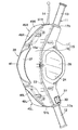
図1〜図8は本発明の一実施例を示すものであり、図1はハンドルカバーの正面図、図2は図1の2−2線断面図、図3は図2の3矢視背面図、図4は図2の4矢視平面図、図5はハンドルカバーの分解斜視図、図6は図1の6−6線拡大断面図、図7は図1の7−7線拡大断面図、図8は右側の方向指示器の斜視図である。 1 to 8 show an embodiment of the present invention. FIG. 1 is a front view of a handle cover, FIG. 2 is a sectional view taken along line 2-2 of FIG. 1, and FIG. 4 is a plan view taken along arrow 4 in FIG. 2, FIG. 5 is an exploded perspective view of the handle cover, FIG. 6 is an enlarged sectional view taken along line 6-6 in FIG. 1, and FIG. 8 and 8 are perspective views of the right direction indicator.
先ず図1〜図4において、自動二輪車が備える操向ハンドル11は、中央部を下方に彎曲させたバー状のハンドル部11aと、該ハンドル部11aの中央部に上端が連設されて下方に延びる軸部11bとを有して略T字状に構成されており、前記軸部11bが、図示しない車体フレームのヘッドパイプに操向可能に支承される。前記ハンドル部11aの左端部にはグリップ12が設けられ、前記ハンドル部11aの右端部にはスロットルグリップ13が回動可能に装着され、スロットルグリップ13を握った右手で操作することを可能としてスロットルグリップ13の前方に配置されるブレーキレバー14が、前記スロットルグリップ13の近傍で前記ハンドル部11aに回動可能に支承される。
1 to 4, a
この操向ハンドル11は、その左端部の前記グリップ12と、その右端部の前記スロットルグリップ13およびブレーキレバー14と、軸部11bの下部とを除いてハンドルカバー15で覆われるものであり、該ハンドルカバー15は、合成樹脂から成る前部および後部カバー半体16,17が分離可能として相互に結合されて成る。
The
図5を併せて参照して、前部カバー半体16および後部カバー半体17は、それらのカバー半体16,17の下部の中央寄り2箇所で前部カバー半体16の前面側から挿通される一対のねじ部材18,18と、前記両カバー半体16,17の中央上部で後部カバー半体17側から挿通される1つのねじ部材19と、前記両カバー半体16,17の両側下部で後部カバー半体17側から挿通される一対のねじ部材20,20とで相互に締結されるものであり、前記操向ハンドル11の軸部11bに固着されたステー21に、後部カバー半体17の中央下部がねじ部材22によって締結される。
Referring also to FIG. 5, the
また前部カバー半体16の上縁部には、下方に向かって突出する複数の位置決め突部16a…が一体に突設されており、後部カバー半体17の上縁部には、各位置決め突部16a…を上方から差し込み得る複数の位置決め孔23…が設けられる。而して各位置決め突部16a…を位置決め孔23…に差し込んだ状態で前記各ねじ部材18…,20…,22によって締結することで前部および後部カバー半体16,17が相互に結合され、ハンドルカバー15が構成される。
Further, a plurality of
後部カバー半体17の中央部にはメータ用開口部24が設けられており、該メータ用開口部24の周囲で後部カバー半体17の内面に突設された複数のメータ取付けボス部25,25…に、前記メータ用開口部24に臨むスピードメータ26が取付けられる。また後部カバー半体17の左側には上下に並ぶ3つのスイッチ用開口部27,28,29が設けられており、ディマスイッチ30、方向指示スイッチ31およびホーンスイッチ32が前記各スイッチ用開口部27〜29に臨むように配設される。また後部カバー半体17の右側には上下に並ぶ2つのスイッチ用開口部33,34が設けられており、アイドルストップスイッチ35およびスタートスイッチ36が前記各スイッチ用開口部33,34に臨むように配設される。
A
前部カバー半体16の中央部に設けられた開口部37には、ヘッドライト38が配設されるものであり、このヘッドライト38は、前方に開放した椀状に形成されるとともに内面をリフレクタとした合成樹脂製のハウジング39と、該ハウジング39内に配置されるようにしてハウジング39に着脱可能に取付けられるバルブ40と、該バルブ40を前方から覆うとともにハウジング39の開口端を塞ぐようにしてハウジング39に取付けられるレンズ41とから成る。
A
前記ヘッドライト38におけるハウジング39の上部は前後に揺動することを可能として前部カバー半体16に支承されており、ハウジング39の下部には、前部カバー半体16の下部内面に当接する脚部39aが一体に設けられ、該脚部39aにはナット42が設けられる。一方、前部カバー半体16の下部には前後に長く延びる長孔43が設けられており、前部カバー半体16の下部外面に当接、係合し得る拡径頭部44aを有するボルト44が、前記長孔43を貫通して前記ナット42に螺合されるものであり、長孔43の長手方向に沿うボルト44の位置を調節することでヘッドライト38の光軸を調節することができる。
The upper portion of the
ところで、前記ヘッドライト38の左右両側には、灯火器である左側および右側の方向指示器45L,45Rがそれぞれ配置されるものであり、ハンドルカバー15における前部カバー半体16の両側には、前方および側方に開放する切欠き部46L,46Rがそれぞれ設けられ、左側および右側の方向指示器45L,45Rはそれらの切欠き部46L,46Rに嵌まり込むようにしてハンドルカバー15の前部カバー半体16に取付けられる。
By the way, left and
図6および図7を併せて参照して、左側の方向指示器45Lは、前部カバー半体16に着脱可能に取付けられる合成樹脂製のハウジング47Lと、該ハウジング47Lに取付けられるバルブ48Lと、該バルブ48Lを前方から覆って前記ハウジング47Lに取付けられるレンズ49Lとから成るものであり、ハウジング47Lの内面には、前記バルブ49Lから放射される光を反射するリフレクタ50が一体に形成される。
6 and 7, the
前記ハウジング47Lは、前記リフレクタ50で反射した光を前方、側方および下方に照射し得る形状を有して椀状に形成されるものであり、このハウジング47Lには、ハンドルカバー15の外面に連なる外観カバー部51Lが一体に形成される。
The
前記外観カバー部51Lは、ハンドルカバー15の左端壁の少なくとも一部、この実施例ではハンドルカバー15の左端壁の略半部を構成するようにして前記ハウジング47Lに一体に形成される。すなわち外観カバー部51Lは、後部カバー半体17に設けられた左側端壁部17aに連なるように形成されており、前記左側端壁部17aおよび外観カバー部51L間に、操向ハンドル11におけるハンドル部11aのグリップ12近傍を貫通せしめる円形の孔52を共同して形成するための半円状の凹部53,54が前記左側端壁部17aおよび外観カバー部51Lにそれぞれ設けられる。
The
また前記ハウジング47Lには、そのハウジング47Lの下部に連なって後方に延びる下部取付け板部55と、前記ハウジング47Lの上部から上方に突出する上部取付け板部56と、前記外観カバー部51Lとは反対側で前記ハウジング47Lの側壁に連なる側部取付け板部57とを一体に有するものである。前記下部取付け板部55にはナット58が装着されており、前部カバー半体16の下部に挿通されるねじ部材59が前記ナット58に螺合される。また前部カバー半体16の内面には、前記上部取付け板部56に当接する取付けボス部60が一体に突設されており、前記上部取付け板部56に挿通されるねじ部材61が取付けボス部60に螺合される。さらに前部カバー半体16の内面には、前記側部取付け板部57に当接する取付けボス部62が一体に突設されており、前記側部取付け板部57に挿通されるねじ部材63が取付けボス部62に螺合される。
Further, the
図8を併せて参照して、右側の方向指示器45Rは、前部カバー半体16に着脱可能に取付けられる合成樹脂製のハウジング47Rと、該ハウジング46Rに取付けられるバルブ48R(図1参照)と、該バルブ48Rを前方から覆って前記ハウジング47Rに取付けられるレンズ49Rとから成り、前記左側の方向指示器45Lとほぼ左右対称に構成され、同様の取付け構造で前部カバー半体16の右側に取付けられる。
Referring also to FIG. 8, a
而して右側の方向指示器45Rが左側の方向指示器45Lと異なるのは、ハンドルカバー15の外面に連なるようにしてハウジング47Rに一体に連設されてハンドルカバー15の右端壁の少なくとも一部(この実施例では略半部)を構成する外観カバー部51Rに、ブレーキレバー14の作動を許容するようにして該ブレーキレバー14を配置するための凹部64が設けられる点であり、後部カバー半体17の右端壁部17bには、ハンドル部11aの略後半部を挿通せしめる半円状の凹部65が設けられる。
Thus, the
ところで、ハンドルカバー15の少なくとも外面が塗装されるのに対し、前記左側および右側の方向指示器45L,45Rにおいて、外観カバー部51L,51Rを含むハウジング47L,47Rは着色樹脂によって形成されるものである。
By the way, at least the outer surface of the
次にこの実施例の作用について説明すると、ハンドルカバー15の左右に配設される灯火器である左右の方向指示器45L,45Rのハウジング47L,47Rは、ハンドルカバー15に着脱可能に取付けられるものであり、しかも前記ハウジング47L,47Rには、ハンドルカバー15の外面に連なる外観カバー部51L,51Rが一体に形成されている。
Next, the operation of this embodiment will be described. The
したがってハンドルカバー15の左右両側に着脱可能に取付けられる方向指示器45L,45Rを有効に利用し、ハンドルカバー15の左右両端部に傷等が生じたときに、方向指示器45L,45Rを交換するだけで対処することができ、ハンドルカバー15全体を交換することを不要としてメンテナンスコストを低減することができる。
Accordingly, the
またハンドルカバー15の両側には、前方および側方に開放した切欠き部46L,46Rが設けられており、それらの切欠き部46L,46Rに嵌まり込むようにして前記方向指示器45L,45Rがハンドルカバー15に取付けられるので、ハンドルカバー15に対する方向指示器45L,45Rの取付けおよび取り外し操作を容易とすることができる。
Further,
また前記外観カバー部51L,51Rが、ハンドルカバー15の左右両端壁の少なくとも一部を構成するようにしてハウジング47L,47Rに一体に形成されるので、ハンドルカバー15の左右両端壁の少なくとも一部が外観カバー部51L,51Rで形成されることになり、傷等が生じ易い箇所に外観カバー部51L,51Rを効果的に配置することができる。
Further, since the
しかもハンドルカバー15の少なくとも外面が塗装されるのに対して、外観カバー部51L,51Rを含むハウジング47L,47Rが着色樹脂から成るものであるので、外観カバー部51L,51Rに傷がついても目立たなくすることが可能であり、外観カバー部51L,51Rに傷がついても方向指示器45L,45Rの交換を極力しないですむようにして、メンテナンスコストをより低減することができる。
Moreover, at least the outer surface of the
さらに方向指示器45L,45Rが備えるハウジング47L,47Rには、バルブ48L,48Rから放射される光を反射するリフレクタ50…が一体に形成されるので、部品点数を低減することができる。
Further, the
以上、本発明の実施例を説明したが、本発明は上記実施例に限定されるものではなく、特許請求の範囲に記載された本発明を逸脱することなく種々の設計変更を行うことが可能である。 Although the embodiments of the present invention have been described above, the present invention is not limited to the above-described embodiments, and various design changes can be made without departing from the present invention described in the claims. It is.
11・・・操向ハンドル
11a・・ハンドル部
15・・・ハンドルカバー
16・・・前部カバー半体
17・・・後部カバー半体
17a・・後部カバー半体の端壁部
45L,45R・・・灯火器としての方向指示器
46L,46R・・・切欠き部
47L,47R・・・ハウジング
48L,48R・・・バルブ
49L,49R・・・レンズ
50・・・リフレクタ
51L,51R・・・外観カバー部
52・・・・孔
53,54・・凹部 11 ... Steering handle
11a ···
17a ···
52 .. Hole
53, 54 .. Recess
Claims (5)
前記前部カバー半体(16)の左右両側に、前方および側方に開放した左右の切欠き部(46L,46R)がそれぞれ設けられると共に、その切欠き部(46L,46R)に嵌まり込むようにして前記左右の灯火器(45L,45R)が前記ハンドルカバー(15)に取付けられ、
左右の前記ハウジング(47L,47R)には、前記後部カバー半体(17)の左右の端壁部(17a)外面に連続し且つその端壁部(17a)と共同して前記ハンドルカバー(15)の左右両端壁をそれぞれ構成する外観カバー部(51L,51R)が一体に形成され、
その外観カバー部(51L,51R)と前記後部カバー半体(17)の端壁部(17a)とには、その相互間に操向ハンドル(11)のハンドル部(11a)を挿通させる孔(52)を共同して形成するための凹部(53,54)がそれぞれ設けられることを特徴とする自動二輪車の前部灯火装置。 The left and right handle cover (15) to front and rear cover half (16, 17) is formed by coupling a housing mounted detachably on the handle cover (15) (47L, 47R), said housing (47L , 47R) and left and right lenses respectively comprising a valve (48L, 48R) attached to the housing (47L, 47R) covering the valve (48L, 48R) from the front and attached to the housing (47L, 47R) . A front lighting device for a motorcycle in which lighting devices (45L, 45R) are respectively disposed,
Left and right cutouts (46L, 46R) opened frontward and laterally are provided on the left and right sides of the front cover half (16), respectively, and are fitted into the cutouts (46L, 46R). The left and right lamps (45L, 45R) are attached to the handle cover (15),
Left and right of the housing (47L, 47R), said rear right and left of the end wall portion of the cover half (17) (17a) continuous teeth and the end wall on the outer surface (17a) and jointly the handle cover ( exterior cover that make up each left and right end walls of 15) (51L, 51R) are formed integrally,
A hole (11a) of the steering handle (11) is inserted between the exterior cover part (51L, 51R) and the end wall part (17a) of the rear cover half (17) ( front lighting equipment of the motorcycle recess for forming jointly a 52) (53, 54), characterized in that the respectively provided.
Priority Applications (4)
| Application Number | Priority Date | Filing Date | Title |
|---|---|---|---|
| JP2004224457A JP4358061B2 (en) | 2004-07-30 | 2004-07-30 | Motorcycle front lighting system |
| TW094112337A TWI262881B (en) | 2004-07-30 | 2005-04-19 | Front lamp device in motorcycle |
| CNB2005100660943A CN100379637C (en) | 2004-07-30 | 2005-04-20 | Headlamp of two-wheel motorcycle |
| KR1020050066684A KR100641672B1 (en) | 2004-07-30 | 2005-07-22 | Front lamp device in motorcycle |
Applications Claiming Priority (1)
| Application Number | Priority Date | Filing Date | Title |
|---|---|---|---|
| JP2004224457A JP4358061B2 (en) | 2004-07-30 | 2004-07-30 | Motorcycle front lighting system |
Publications (2)
| Publication Number | Publication Date |
|---|---|
| JP2006044321A JP2006044321A (en) | 2006-02-16 |
| JP4358061B2 true JP4358061B2 (en) | 2009-11-04 |
Family
ID=35926803
Family Applications (1)
| Application Number | Title | Priority Date | Filing Date |
|---|---|---|---|
| JP2004224457A Expired - Fee Related JP4358061B2 (en) | 2004-07-30 | 2004-07-30 | Motorcycle front lighting system |
Country Status (4)
| Country | Link |
|---|---|
| JP (1) | JP4358061B2 (en) |
| KR (1) | KR100641672B1 (en) |
| CN (1) | CN100379637C (en) |
| TW (1) | TWI262881B (en) |
Families Citing this family (8)
| Publication number | Priority date | Publication date | Assignee | Title |
|---|---|---|---|---|
| JP5137254B2 (en) * | 2008-09-25 | 2013-02-06 | 本田技研工業株式会社 | Motorcycle winker equipment |
| JP5335493B2 (en) * | 2009-03-10 | 2013-11-06 | 本田技研工業株式会社 | Blinker mounting structure for saddle riding type vehicles |
| JP2011031817A (en) * | 2009-08-04 | 2011-02-17 | Yamaha Motor Co Ltd | Motorcycle |
| JP5615637B2 (en) | 2010-09-15 | 2014-10-29 | 川崎重工業株式会社 | Motorcycle front cowl |
| JP5335760B2 (en) * | 2010-12-10 | 2013-11-06 | 本田技研工業株式会社 | Motorcycle lighting equipment |
| JP5784434B2 (en) * | 2011-09-20 | 2015-09-24 | 本田技研工業株式会社 | Vehicle front structure |
| JP5750019B2 (en) * | 2011-09-29 | 2015-07-15 | 本田技研工業株式会社 | Motorcycle |
| CN106394745A (en) * | 2016-10-13 | 2017-02-15 | 江门市大长江集团有限公司 | Motorcycle head structure and mounting method thereof |
Family Cites Families (7)
| Publication number | Priority date | Publication date | Assignee | Title |
|---|---|---|---|---|
| GB2108449B (en) * | 1981-08-28 | 1985-08-07 | Honda Motor Co Ltd | Legshield/luggage device for vehicles |
| JP3254895B2 (en) * | 1994-04-27 | 2002-02-12 | スズキ株式会社 | Integrated electrical unit for small vehicles |
| JP3216964B2 (en) * | 1994-11-22 | 2001-10-09 | 株式会社小糸製作所 | Motorcycle headlamps |
| JP4297229B2 (en) * | 1999-02-24 | 2009-07-15 | 本田技研工業株式会社 | Motorcycle lighting equipment |
| JP2001260965A (en) * | 2000-03-17 | 2001-09-26 | Honda Motor Co Ltd | Vehicle having transparent or semitransparent body cover |
| JP3741942B2 (en) * | 2000-08-01 | 2006-02-01 | 本田技研工業株式会社 | Front and rear lighting equipment for motorcycles and tricycles |
| JP4092134B2 (en) * | 2002-05-09 | 2008-05-28 | 本田技研工業株式会社 | Front turn signal mounting structure for motorcycles |
-
2004
- 2004-07-30 JP JP2004224457A patent/JP4358061B2/en not_active Expired - Fee Related
-
2005
- 2005-04-19 TW TW094112337A patent/TWI262881B/en not_active IP Right Cessation
- 2005-04-20 CN CNB2005100660943A patent/CN100379637C/en active Active
- 2005-07-22 KR KR1020050066684A patent/KR100641672B1/en not_active IP Right Cessation
Also Published As
| Publication number | Publication date |
|---|---|
| TW200604050A (en) | 2006-02-01 |
| JP2006044321A (en) | 2006-02-16 |
| TWI262881B (en) | 2006-10-01 |
| CN1727246A (en) | 2006-02-01 |
| KR20060046585A (en) | 2006-05-17 |
| CN100379637C (en) | 2008-04-09 |
| KR100641672B1 (en) | 2006-11-03 |
Similar Documents
| Publication | Publication Date | Title |
|---|---|---|
| KR100641672B1 (en) | Front lamp device in motorcycle | |
| US7401953B2 (en) | Motorcycle | |
| US7559679B2 (en) | Vehicle light apparatus and motorcycle having the light apparatus | |
| US20150124467A1 (en) | Headlight device of motorcycle | |
| US20070230202A1 (en) | Vehicle light unit | |
| JP5856523B2 (en) | Motorcycle lighting equipment | |
| JP3592707B2 (en) | Rear combination lamp for motorcycle | |
| JP2008081082A5 (en) | ||
| JP4052842B2 (en) | Lamp mounting structure for motorcycles | |
| JP2004189019A (en) | Rear-view mirror device | |
| JP6125308B2 (en) | Vehicle taillight device | |
| JP4594566B2 (en) | Motorcycle lamp unit | |
| JP2001088758A (en) | Light unit of motorcycle | |
| BRPI0604947B1 (en) | flashlight device for vehicle use | |
| JP3254895B2 (en) | Integrated electrical unit for small vehicles | |
| JP5592859B2 (en) | Rear lamp structure of motorcycle | |
| EP3118093B1 (en) | Direction indicator structure of vehicle | |
| JP2009214618A (en) | Saddle-riding type vehicle | |
| JP6858741B2 (en) | Headlights for saddle-riding vehicles | |
| TWI438113B (en) | Straddle type vehicle | |
| JP3608369B2 (en) | Rear combination lamp for motorcycle | |
| JPH10166937A (en) | Tail lamp structure for motorcycle | |
| JP6054656B2 (en) | Vehicle lighting | |
| JP2005119430A (en) | Working vehicle lamp | |
| TWI495590B (en) | Saddle riding type vehicle |
Legal Events
| Date | Code | Title | Description |
|---|---|---|---|
| A621 | Written request for application examination |
Free format text: JAPANESE INTERMEDIATE CODE: A621 Effective date: 20061129 |
|
| A977 | Report on retrieval |
Free format text: JAPANESE INTERMEDIATE CODE: A971007 Effective date: 20081120 |
|
| A131 | Notification of reasons for refusal |
Free format text: JAPANESE INTERMEDIATE CODE: A131 Effective date: 20081126 |
|
| A521 | Request for written amendment filed |
Free format text: JAPANESE INTERMEDIATE CODE: A523 Effective date: 20090126 |
|
| TRDD | Decision of grant or rejection written | ||
| A01 | Written decision to grant a patent or to grant a registration (utility model) |
Free format text: JAPANESE INTERMEDIATE CODE: A01 Effective date: 20090722 |
|
| A01 | Written decision to grant a patent or to grant a registration (utility model) |
Free format text: JAPANESE INTERMEDIATE CODE: A01 |
|
| A61 | First payment of annual fees (during grant procedure) |
Free format text: JAPANESE INTERMEDIATE CODE: A61 Effective date: 20090805 |
|
| FPAY | Renewal fee payment (event date is renewal date of database) |
Free format text: PAYMENT UNTIL: 20120814 Year of fee payment: 3 |
|
| R150 | Certificate of patent or registration of utility model |
Ref document number: 4358061 Country of ref document: JP Free format text: JAPANESE INTERMEDIATE CODE: R150 Free format text: JAPANESE INTERMEDIATE CODE: R150 |
|
| FPAY | Renewal fee payment (event date is renewal date of database) |
Free format text: PAYMENT UNTIL: 20120814 Year of fee payment: 3 |
|
| FPAY | Renewal fee payment (event date is renewal date of database) |
Free format text: PAYMENT UNTIL: 20130814 Year of fee payment: 4 |
|
| FPAY | Renewal fee payment (event date is renewal date of database) |
Free format text: PAYMENT UNTIL: 20140814 Year of fee payment: 5 |
|
| R250 | Receipt of annual fees |
Free format text: JAPANESE INTERMEDIATE CODE: R250 |
|
| LAPS | Cancellation because of no payment of annual fees |