JP4356434B2 - 3-level inverter circuit - Google Patents
3-level inverter circuit Download PDFInfo
- Publication number
- JP4356434B2 JP4356434B2 JP2003397250A JP2003397250A JP4356434B2 JP 4356434 B2 JP4356434 B2 JP 4356434B2 JP 2003397250 A JP2003397250 A JP 2003397250A JP 2003397250 A JP2003397250 A JP 2003397250A JP 4356434 B2 JP4356434 B2 JP 4356434B2
- Authority
- JP
- Japan
- Prior art keywords
- package
- packages
- terminal
- level inverter
- diode
- Prior art date
- Legal status (The legal status is an assumption and is not a legal conclusion. Google has not performed a legal analysis and makes no representation as to the accuracy of the status listed.)
- Expired - Lifetime
Links
- 230000008878 coupling Effects 0.000 claims description 69
- 238000010168 coupling process Methods 0.000 claims description 69
- 238000005859 coupling reaction Methods 0.000 claims description 69
- 238000010586 diagram Methods 0.000 description 23
- 239000003990 capacitor Substances 0.000 description 13
- 230000004888 barrier function Effects 0.000 description 11
- 239000004020 conductor Substances 0.000 description 10
- 230000009467 reduction Effects 0.000 description 6
- 230000007423 decrease Effects 0.000 description 5
- 238000009413 insulation Methods 0.000 description 5
- 238000000034 method Methods 0.000 description 5
- 230000000694 effects Effects 0.000 description 4
- 125000006850 spacer group Chemical group 0.000 description 3
- 230000008859 change Effects 0.000 description 2
- 238000006243 chemical reaction Methods 0.000 description 2
- 238000001816 cooling Methods 0.000 description 2
- 238000003475 lamination Methods 0.000 description 2
- 230000007935 neutral effect Effects 0.000 description 2
- 238000000926 separation method Methods 0.000 description 2
- 230000002776 aggregation Effects 0.000 description 1
- 238000004220 aggregation Methods 0.000 description 1
- 238000013459 approach Methods 0.000 description 1
- 230000005540 biological transmission Effects 0.000 description 1
- 230000003247 decreasing effect Effects 0.000 description 1
- 238000010030 laminating Methods 0.000 description 1
- 239000000463 material Substances 0.000 description 1
- 230000002265 prevention Effects 0.000 description 1
- 230000011218 segmentation Effects 0.000 description 1
- 239000013585 weight reducing agent Substances 0.000 description 1
Images


Classifications
-
- H—ELECTRICITY
- H02—GENERATION; CONVERSION OR DISTRIBUTION OF ELECTRIC POWER
- H02M—APPARATUS FOR CONVERSION BETWEEN AC AND AC, BETWEEN AC AND DC, OR BETWEEN DC AND DC, AND FOR USE WITH MAINS OR SIMILAR POWER SUPPLY SYSTEMS; CONVERSION OF DC OR AC INPUT POWER INTO SURGE OUTPUT POWER; CONTROL OR REGULATION THEREOF
- H02M7/00—Conversion of ac power input into dc power output; Conversion of dc power input into ac power output
- H02M7/42—Conversion of dc power input into ac power output without possibility of reversal
- H02M7/44—Conversion of dc power input into ac power output without possibility of reversal by static converters
- H02M7/48—Conversion of dc power input into ac power output without possibility of reversal by static converters using discharge tubes with control electrode or semiconductor devices with control electrode
- H02M7/493—Conversion of dc power input into ac power output without possibility of reversal by static converters using discharge tubes with control electrode or semiconductor devices with control electrode the static converters being arranged for operation in parallel
-
- H—ELECTRICITY
- H02—GENERATION; CONVERSION OR DISTRIBUTION OF ELECTRIC POWER
- H02M—APPARATUS FOR CONVERSION BETWEEN AC AND AC, BETWEEN AC AND DC, OR BETWEEN DC AND DC, AND FOR USE WITH MAINS OR SIMILAR POWER SUPPLY SYSTEMS; CONVERSION OF DC OR AC INPUT POWER INTO SURGE OUTPUT POWER; CONTROL OR REGULATION THEREOF
- H02M7/00—Conversion of ac power input into dc power output; Conversion of dc power input into ac power output
- H02M7/42—Conversion of dc power input into ac power output without possibility of reversal
- H02M7/44—Conversion of dc power input into ac power output without possibility of reversal by static converters
- H02M7/48—Conversion of dc power input into ac power output without possibility of reversal by static converters using discharge tubes with control electrode or semiconductor devices with control electrode
- H02M7/483—Converters with outputs that each can have more than two voltages levels
- H02M7/487—Neutral point clamped inverters
Description
本発明は、3レベルインバータ回路に関するものであり、特に回路を構成するパッケージの配置に関するものである。 The present invention relates to a three-level inverter circuit, and more particularly to the arrangement of packages constituting the circuit.
入力の直流電圧を切り刻んで出力電圧をパルス形状にし、そのパルスの数、間隔、幅などを制御し、目的とする3レベルの周波数の交流を出力するPWM(Pulse Width Modulation)制御の3レベルインバータ回路においては、近年、パワーデバイス用の素子として、小形・軽量化、低損失・高効率化、騒音・高調波・トルク変動防止、信頼性の向上等の観点から、IGBT(Insulated Gate Bipolar Transistor)が用いられている。 PWM (Pulse Width Modulation) control 3-level inverter that cuts input DC voltage into output voltage and controls the number, interval, width, etc. of the pulse, and outputs AC with the desired 3-level frequency In recent years, IGBTs (Insulated Gate Bipolar Transistors) have been used as power device elements in terms of miniaturization and weight reduction, low loss and high efficiency, noise, harmonics and torque fluctuation prevention, and improved reliability. Is used.
一方、このような3レベルインバータ回路において、各パッケージ間の配線インダクタンスの数値が大きいとターンオフサージ電圧が高くなることがある。そして、このターンオフサージ電圧をIGBTの安全動作領域以内に抑えられない場合には、IGBTが破壊してしまう。
このターンオフサージ電圧を抑制する方法として、別途にコンデンサを用いて配線インダクタンスのエネルギーを吸収するスナバ回路を、各IGBTと並列に接続する方法がある。しかしながら、配線インダクタンスが大きい場合、そのエネルギーを吸収するスナバ回路のコンデンサ容量も大きくなり、装置外形の大型化、装置コストの増加、部品数の増大による信頼性の低下、装置損失の増加等の問題を招くことになる。
On the other hand, in such a three-level inverter circuit, if the value of the wiring inductance between the packages is large, the turn-off surge voltage may increase. If the turn-off surge voltage cannot be suppressed within the safe operation area of the IGBT, the IGBT is destroyed.
As a method for suppressing the turn-off surge voltage, there is a method in which a snubber circuit that absorbs the energy of wiring inductance is separately connected in parallel to each IGBT using a capacitor. However, when the wiring inductance is large, the capacitor capacity of the snubber circuit that absorbs the energy also increases, causing problems such as an increase in the size of the device, an increase in device cost, a decrease in reliability due to an increase in the number of components, and an increase in device loss. Will be invited.
このような問題を解消する1つの方法として、特許文献1には、以下の方法が提案されている。すなわち、特許文献1に記載の3レベル電力変換装置においては、同文献の図1に示されるように、中央に直流電源9を配置し、この直流電源9を通る直線に沿うように、第2のIGBT2−第1の結合ダイオード5−第1のIGBT1をこの順で配置し、これに対して直流電源9の反対側で直線に沿うように、第3のIGBT3−第2の結合ダイオード5−第4のIGBT4をこの順で配置する。そして、第1から第4のIGBT1〜4及び第1,第2の結合ダイオード5,5のすべての接続端子を一方向に向けて突出させ、電気的に絶縁された複数の平板状の配線板群(積層接続板)30によって第1から第4のIGBT1〜4及び第1,第2の結合ダイオード5,5の接続端子間に必要な電気的接続を行う。このような構成とすることにより、各パッケージの接続端子を直線に沿って配置してこれらの各接続端子間の配線を短くするとともに、流れる電流の往路と復路となる電流路の離間距離を小さくして、電流路に存在する配線インダクタンスを低減している。そして、スナバ回路を不要としている。
As one method for solving such a problem,
また、特許文献2に記載の3レベルインバータのパワーモジュールスタックにおいては、上述特許文献1に記載の装置と同じ目的、すなわち配線インダクタンスを低減するという目的と、これに加えて、素子を効率よく冷却する目的で、同文献の図1に示されるように、冷却用フィンベース10の両面に夫々背面を対向させて第1のスイッチング素子1、第1のダイオード5及び第2のスイッチング素子2と、第4のスイッチング素子4、第2のダイオード6及び第3のスイッチング素子3とを各々順次接続順に配設し、フィンベース10を囲って全体としてコ字形状になるように配置し、絶縁板を挟んで形成した接続板(積層接続板)で接続している。
Further, in the power module stack of the three-level inverter described in
さらに、特許文献3に記載の3レベル電力変換装置の主回路においては、同文献の図1に示されるように、同じく配線インダクタンスを低減する目的で、上アームユニット1のIGBT21のエミッタとIGBT22のコレクタとクランプダイオード41のカソードとを直線上に配置し、これらの端子を接続導体11で接続し、IGBT21の電源側の接続導体7と中性点の接続導体9とを近づけて且つ平行に配置し、また交流側端子の接続導体10と接続導体9とを近づけて且つ平行に配置し、下アームユニット2のIGBT23のエミッタとIGBT24のコレクタとクランプダイオード42のカソードとを直線上に配置し、これらの端子を接続導体12で接続し、IGBT24の電源側の接続導体8と中性点の接続導体9とを近接して平行に配置し、また交流側端子の接続導体10と接続導体9とを近接して平行に配置することで、電流路の配線インダクタンスを減少させている。
しかしながら、高電圧の回路に使用する結合ダイオードにおいては接続端子カソード−アノード間に板状の絶縁バリアを有するものが多い。この絶縁バリアは接続端子の方向にも突出している。そのため、上述のようにスイッチング素子(IGBT)と結合ダイオードとを同一の直線上に並べると、絶縁バリアが積層接続板に干渉してしまう。そのため、各パッケージ間の電気的接続を単純な平板状の積層接続板で行うことができない。すなわち、積層接続板が複雑な形状となったり、別途スペーサが必要となったりする。
この発明は、上述のような課題を解決するためになされたもので、スナバ回路を必要とすることなくターンオフサージ電圧を抑制することができるとともに、各部品間に必要な電気的な接続をする接続手段の構造を簡略化することができ、また、装置の小型・薄型化を実現することのできる3レベルインバータ回路を提供することを目的とする。
However, many coupling diodes used in high voltage circuits have a plate-like insulating barrier between the connection terminal cathode and anode. This insulation barrier also protrudes in the direction of the connection terminal. Therefore, when the switching element (IGBT) and the coupling diode are arranged on the same straight line as described above, the insulating barrier interferes with the laminated connection plate. Therefore, electrical connection between the respective packages cannot be performed with a simple flat plate-like laminated connection plate. That is, the laminated connecting plate may have a complicated shape, or a separate spacer may be required.
The present invention has been made to solve the above-described problems, and can suppress a turn-off surge voltage without requiring a snubber circuit and also make necessary electrical connections between components. It is an object of the present invention to provide a three-level inverter circuit that can simplify the structure of the connecting means and can realize a reduction in size and thickness of the device.
この発明の第1の発明に係る3レベルインバータ回路は、スイッチング素子を内蔵した複数の素子パッケージと、結合ダイオードを内蔵した複数のダイオードパッケージとを載置面に配置し、各パッケージの接続端子を、積層接続板を介して接続するようにした3レベルインバータ回路において、前記素子パッケージ列の一端側に直流電源を並設し、前記複数の素子パッケージは、前記直流電源とは反対側から直流電源に向かって配列された第1、第2、第3及び第4の4つの素子パッケージで構成され、第1〜第4の素子パッケージの夫々は1つのスイッチング素子を内蔵し、前記複数のダイオードパッケージは、第2及び第3の素子パッケージの配列方向と直交する方向に所定距離離れて配置された第1及び第2のダイオードパッケージで構成され、前記積層接続板は、前記直流電源の正極端子と前記第1の素子パッケージの正極側端子とを接続し、且つ第1〜第4の素子パッケージを覆う第1の導電性接続板部と、前記第1のダイオードパッケージのアノード端子及び第2のダイオードパッケージのカソード端子と前記直流電源の中間端子とを接続し、且つ第1〜第4の素子パッケージを覆う第2の導電性接続板部と、その他の端子を接続する第3の導電性接続板部とが絶縁板部を介して積層された構造を有する。 According to a first aspect of the present invention, a three-level inverter circuit includes a plurality of element packages each including a switching element and a plurality of diode packages each including a coupling diode arranged on a mounting surface, and connection terminals of the respective packages are provided. In the three-level inverter circuit that is connected via the laminated connection plate , a DC power source is arranged in parallel on one end side of the element package row, and the plurality of element packages are connected to the DC power source from the side opposite to the DC power source. Each of the first, second, third and fourth element packages, each of the first to fourth element packages including one switching element, and the plurality of diode packages. Are the first and second diode packages disposed at a predetermined distance in a direction orthogonal to the arrangement direction of the second and third element packages. The laminated connection plate is configured to connect a positive electrode terminal of the DC power source and a positive electrode side terminal of the first element package, and cover the first to fourth element packages. A second conductive connection plate connecting the anode terminal of the first diode package and the cathode terminal of the second diode package and the intermediate terminal of the DC power source and covering the first to fourth element packages and parts, and the third conductive connecting plate portion for connecting the other terminal to have a laminated structure through an insulating plate.
この発明の第2の発明に係る3レベルインバータ回路においては、前記直流電源の電源端子と前記素子パッケージ及び前記ダイオードパッケージの接続端子との間を、少なくとも当該ダイオードパッケージのアノード端子及びカソード端子の中間部が露出するように前記積層接続板で覆って、電気的に接続する。 In the three-level inverter circuit according to a second aspect of the invention, between the power supply terminal of the DC power supply and said element package and the connection terminals of the diode package, the anode and cathode terminals of at least the diode package intermediate parts covered with the laminated connection plate so as to expose, electrically connected.
この発明の第3の発明に係る3レベルインバータ回路においては、前記第3の導電性接続板部は、前記第1の素子パッケージの負極側端子、第2の素子パッケージの正極側端子及び第1のダイオードパッケージのカソード端子を接続する第1の分割接続板と、第2の素子パッケージの負極側端子及び第3の素子パッケージの正極側端子を接続し、且つ交流出力端子を有する第2の分割接続板と、第3の素子パッケージの負極側端子、第4の素子パッケージの正極側端子及び第2のダイオードパッケージのアノードを接続する第3の分割接続板と、第4の素子パッケージの負極側端子と直流電源の負極端子とを接続する第4の分割接続板とで構成されている。 In the three-level inverter circuit according to a third aspect of the present invention, the third conductive connecting plate portion includes a negative terminal on the first element package, a positive terminal on the second element package, and a first terminal. A first divided connection plate for connecting a cathode terminal of the diode package, a negative electrode side terminal of the second element package, and a positive electrode side terminal of the third element package, and having an AC output terminal A connection plate, a third divided connection plate for connecting the negative electrode side terminal of the third element package, the positive electrode side terminal of the fourth element package, and the anode of the second diode package, and the negative electrode side of the fourth element package that consists of a fourth sub-connection plate for connecting the negative terminal of the terminal and the DC power source.
この発明の第4の発明に係る3レベルインバータ回路においては、前記複数の素子パッケージと前記複数のダイオードパッケージは、夫々1つの素子を内蔵している。 In the three-level inverter circuit according to the fourth aspect of the present invention, each of the plurality of element packages and the plurality of diode packages incorporates one element .
この発明の第5の発明に係る3レベルインバータ回路においては、前記複数の素子パッケージと前記複数のダイオードパッケージは、夫々2つの素子を内蔵し、夫々細長状をなし、前記複数の素子パッケージは夫々長手方向を前記直線に直交して配置し、隣り合う2個の前記素子パッケージに対して、前記1個のダイオードパッケージを、3個のパッケージがコ字型となるように配置されている。 In the three-level inverter circuit according to a fifth aspect of the invention, the plurality of diode package and the plurality of device packages incorporates a respective two elements, without the respective elongated, the plurality of device packages are each The longitudinal direction is arranged perpendicular to the straight line, and the one diode package is arranged so that the three packages are U-shaped with respect to the two adjacent element packages.
第1の発明においては、複数の素子パッケージをその入力側接続端子及び出力側接続端子が直線に沿うように配置して素子パッケージ列を形成すると共に、複数のダイオードパッケージを素子パッケージ列の配列方向と直交する方向に離間させて配置するので、複数の素子パッケージをダイオードパッケージを避け積層接続板で容易に接続することができる。 In the first invention, the plurality of element packages are arranged so that the input side connection terminals and the output side connection terminals thereof are along a straight line to form an element package row, and the plurality of diode packages are arranged in the arrangement direction of the element package rows. Therefore, a plurality of element packages can be easily connected by a laminated connection plate avoiding the diode package.
また、第1の発明においては、素子パッケージ列の一端側に直流電源を並設し、この直流電源の電源端子と素子パッケージ及びダイオードパッケージの接続端子との間を積層接続板で電気的に接続するので、素子パッケージの接続端子と直流電源の接続端子との間の積層接続板に形成される電流路において、往路と復路の離間距離を或る程度小さくすることができ、電流路に存在する配線インダクタンスを減少させることができる。 In the first invention, a DC power supply is arranged in parallel on one end side of the element package row, and the power supply terminal of the DC power supply and the connection terminals of the element package and the diode package are electrically connected by the laminated connection plate. Therefore, in the current path formed in the laminated connection plate between the connection terminal of the element package and the connection terminal of the DC power supply, the separation distance between the forward path and the return path can be reduced to some extent, and exists in the current path. Wiring inductance can be reduced.
さらに、第1の発明においては、第2及び第3の素子パッケージの接続端子と第1及び第2のダイオードパッケージの接続端子との間の配線を短くし配線インダクタンスを減少させることができる。さらに第1〜第4の素子パッケージの接続端子と直流電源の接続端子との間に形成される電流路において、往路と復路の離間距離を或る程度小さくすることができ、電流路に存在する配線インダクタンスを減少させることができる。
また、第2の発明においては、少なくともダイオードパッケージのアノード端子及びカソード端子の中間部が露出するので、ダイオードパッケージが絶縁バリアを有するものであっても、積層接続板を平板状のものとすることができる。 Furthermore, in the first invention, the wiring between the connection terminals of the second and third element packages and the connection terminals of the first and second diode packages can be shortened to reduce the wiring inductance. Further, in the current path formed between the connection terminals of the first to fourth element packages and the connection terminal of the DC power supply, the separation distance between the forward path and the return path can be reduced to some extent and exists in the current path. Wiring inductance can be reduced.
In the second invention, at least the middle part of the anode terminal and the cathode terminal of the diode package is exposed. Therefore, even if the diode package has an insulation barrier, the laminated connection plate should have a flat plate shape. Can do.
第3の発明においては、第1の導電性接続板部に形成される直流電源の正極端子と第1の素子パッケージとの間の電流路と、第1のダイオードパッケージのアノード端子及び第2のダイオードパッケージのカソード端子と直流電源の中間端子との間の電流路が違いに近づき且つ反対方向となるので、電流により発生する磁界が互いに打ち消し合うように作用し、配線インダクタンスがさらに低減される。 In the third invention, the current path between the positive electrode terminal of the DC power source formed on the first conductive connection plate portion and the first element package, the anode terminal of the first diode package, and the second Since the current path between the cathode terminal of the diode package and the intermediate terminal of the DC power supply approaches a difference and is in the opposite direction, the magnetic fields generated by the currents cancel each other, and the wiring inductance is further reduced.
第4の発明においては、素子パッケージとダイオードパッケージはそれぞれ1つの素子を内蔵しているので、1つのインバータ回路を構成する各パッケージの接続端子を3層の積層接続板で接続することができる。
第5の発明においては、素子パッケージとダイオードパッケージは夫々2つのスイッチング素子を内蔵し、またコ字型となるように配置されているので、複数のスイッチング素子を面積効率よく、且つ各パッケージ間の配線を短くすることができる。
In the fourth invention, each of the element package and the diode package incorporates one element, so that the connection terminals of each package constituting one inverter circuit can be connected by a three-layer laminated connection plate.
In the fifth invention, each of the element package and the diode package incorporates two switching elements and is arranged so as to have a U-shape. Wiring can be shortened.
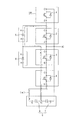
図1はこの発明の第1の実施形態の3レベルインバータ装置の素子パッケージ配置及びパッケージ間接続を示す構成図である。図1において、3レベルインバータ装置100は、第1の3レベルインバータ回路101と第2の3レベルインバータ回路102とを有している。
第1の3レベルインバータ回路101と第2の3レベルインバータ回路102は、中心線γに対して線対称に形成されており、全く同様の回路構成を有している。そのため、第2の3レベルインバータ回路102の説明は省略し、第1の3レベルインバータ回路101のみの説明をする。
FIG. 1 is a configuration diagram showing element package arrangement and inter-package connection of the three-level inverter device according to the first embodiment of the present invention. In FIG. 1, a three-
The first three-
3レベルインバータ回路101は、スイッチング素子を内蔵した素子パッケージIGBT(insulated Gate Bipolar Transistor)である4個の素子パッケージ1〜4(以下、単にIGBTとも言う)と、結合ダイオードを内蔵した2個のダイオードパッケージ5,6(以下、単に結合パッケージとも言う)と、直流電源9とを有している。そしてさらに、これらのパッケージを必要な箇所において相互に電気的に接続する接続手段(図1では配線として表されている)を有している。
The three-
第1から第4のIGBT1〜4は、第1の直線αに沿って配置され素子パッケージ列を形成している。そして、直流電源9もほぼ直線αに沿って配置されている。4個のIGBTは、直流電源9の側から、第4のIGBT4、第3のIGBT3、第2のIGBT2、第1のIGBT1の順で配置されている。第1から第4のIGBT1〜4は、概ね直線α上に配置されれば良いが、各IGBT1〜4の接続端子であるコレクタC及びエミッタEは正確に直線α上に配置されていることが望ましい。
The first to
第1,第2の結合ダイオード5,6は、第1の直線αに対して中央線γとは反対側に所定の距離れて且つ第1の直線αに対して平行となる第2の直線βに沿って配置されている。さらに詳しくは、第1の結合ダイオード5は、第2の直線β上の第2のIGBT2と対向する位置に配置され、また第2の結合ダイオード6は、第2の直線β上の第3のIGBT3と対向する位置に配置されている。直流電源9は、コンデンサ7,8が直列に接続されて構成され、正極端子P、中間端子M及び負極端子Nが設けられている。直流電源9には、実際には電力供給用の結線が接続されているが図では省略している。本発明の特徴は、この第1,第2の結合ダイオード5が、直線状に並べられた第1から第4のIGBT1〜4からずれた位置に配置されている点にあり、この点について説明して行く。
The first and
第1のIGBT1のコレクタCは直流電源9の正極端子Pに接続され、同エミッタEは第2のIGBT2のコレクタC及び第1の結合ダイオード5のカソードKに接続されている。第1の結合ダイオード5のアノードAは直流電源9の中間端子M及び第2の結合ダイオード6のカソードKに接続されている。第2のIGBT2のエミッタEは交流出力端子ACに接続されている。
また、第3のIGBT3のコレクタCは交流出力端子ACに接続され、同エミッタEは第4のIGBT4のコレクタC及び第2の結合ダイオード6のアノードAに接続されている。第2の結合ダイオード6のカソードKは直流電源9の中間端子Mに接続され、第4のIGBT4のエミッタEは直流電源9の負極端子Nに接続されている。
The collector C of the
The collector C of the
図2は図1の3レベルインバータ回路101の回路図であり、同時に、3レベルインバータ回路101の6つのモード(モード1〜モード6)の各モードにおける電流経路を説明する図である。なお、図2中のL1〜L5は回路に存在する配線インダクタンスを示している。
図2(ア)は回路101がモード1からモード2へ変化する時の電流経路を説明する図である。IGBT1、IGBT2がオンし、IGBT3、IGBT4がオフした状態のモード1では、電流がコンデンサ7→配線インダクタンスL1→IGBT1→IGBT2→交流出力端子ACの経路で流れる(電流(1))。
FIG. 2 is a circuit diagram of the three-
FIG. 2A is a diagram for explaining a current path when the
次に、状態がモード1からモード2へ変化するとき、IGBT1がターンオフし、電流は、中間端子M→配線インダクタンスL2→結合ダイオード5→配線インダクタンスL3→IGBT2→交流出力端子ACの経路に転流する(電流(2))。このとき、配線インダクタンスL1を介してIGBT1に流れていた電流(1)は減少し、逆に、配線インダクタンスL2、結合ダイオード5、配線インダクタンスL3を介してIGBT2に流れる電流は増加する。従って、配線インダクタンスL1には電流(1)の減少率−di/dtによる電圧=−di/dt×L1=V1が図示矢印の向きに誘起される。また、配線インダクタンスL2,L3には、それぞれ、電流(2)の増加率di/dtによる電圧=di/dt×L2=V2,di/dt×L3=V3が同じく図示矢印の向きに誘起される。このため、この転流時には、IGBT1には、コンデンサ7の電圧+V1+V2+V3の電圧がサージ電圧として印加されることになる。
Next, when the state changes from
図2(イ)は回路101がモード2からモード3へ変化する時の電流経路を説明する図である。モード2からモード3に変化するとき、IGBT2がターンオフするため電流(2)が減少し、配線インダクタンスL5を介してIGBT3、IGBT4のフライホイールダイオードを流れる電流が増加する。この結果、配線インダクタンスL2,L3には電流(2)の減少率−di/dtによる電圧=−di/dt×L2=V2,−di/dt×L3=V3が図示矢印の向きに誘起される。また配線インダクタンスL5には、電流(3)の増加率di/dtによる電圧=di/dt×L5=V5が図示矢印の向きに誘起される。このため、この転流時に、IGBT2にはコンデンサ8の電圧+V2+V3+V5の電圧がサージ電圧として印加されることになる。
FIG. 2A is a diagram for explaining a current path when the
図2(ウ)は回路101がモード4からモード5へ変化する時の電流経路を説明する図である。IGBT3、IGBT4がオンし、IGBT1、IGBT2がオフした状態のモード4では、電流は、交流出力端子AC→IGBT3→IGBT4→配線インダクタンスL5→負極端子Nの経路で流れている(電流(4))。次に、モード4からモード5へ変化するとき、IGBT4がターンオフし、電流が交流出力端子AC→IGBT3→配線インダクタンスL4→結合ダイオード2→配線インダクタンスL2→中間端子Mの経路に転流する(電流(5))。このとき、IGBT4を介して配線インダクタンスL5に流れていた電流(4)は減少し、逆に配線インダクタンスL4、L2を介して結合ダイオード2に流れる電流は増加する。従って、配線インダクタンスL5には電流(4)の減少率−di/dtによる電圧=−di/dt×L5が図示矢印の向きに誘起される。また、配線インダクタンスL2,L4には、それぞれ電流(5)の増加率di/dtによる電圧=di/dt×L2=V2,di/dt×L4=V4が図示矢印の向きに誘起される。このため、この転流時には、IGBT4には、コンデンサ8の電圧+V5+V2+V4の電圧がサージ電圧として印加されることになる。
FIG. 2C illustrates a current path when the
図2(エ)は回路101がモード5からモード6へ変化する時の電流経路を説明する図である。モード5からモード6に変化するとき、IGBT3がターンオフするため電流(5)が減少し、配線インダクタンスL1を介してIGBT1及びIGBT2のフライホイールダイオードを流れる電流(6)が増加する。従って、配線インダクタンスL2,L4には電流(5)の減少率−di/dtによる電圧=−di/dt×L2=V2,−di/dt×L4=V4が図示矢印の向きに誘起される。また、配線インダクタンスL1には、電流(6)の増加率di/dtによる電圧=di/dt×L1=V1が図示矢印の向きに誘起される。このため、この転流時に、IGBT3には、コンデンサ7の電圧+V2+V4+V1の電圧がサージ電圧として印加されることになる。
FIG. 2D is a diagram for explaining a current path when the
そして、上述の転流動作の中で最も配線インダクタンスが大きくなる時は、図2(イ)に示されたモード2からモード3への変化時と、図2(エ)に示されたモード5からモード6への変化時である。すなわち、図2(イ)に示された一点鎖線の電流路(a)及び、図2(エ)に示された二点鎖線の電流路(a)にサージ電圧が印加されるときである。そのため、上述の転流動作によるサージ電圧(ターンオフサージ電圧)を低減するには、電流路(a)及び(b)における配線インダクタンスを小さくしてやればよい。そして、電流路の配線インダクタンスを小さくするには、その配線長さを短くするか、或いは、電流路を互いに近接する往復路で形成し、当該往復路を流れる電流により発生する磁界を互いに打ち消し合うようにすればよい。これに関しては、各パッケージ間の電気的な接続手段である積層バスバー40の説明の際に詳しく述べる。
When the wiring inductance becomes the largest in the above commutation operation, the
図3は図1に示す3レベルインバータ回路101の素子パッケージ配置に電流路(a)を一点鎖線で付記したものである。図4は同じく図1の素子パッケージ配置に電流路(b)を二点鎖線で付記したものである。
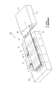
図5は本実施形態の3レベルインバータ装置100の回路101に相当する部分の斜視図である。図6は積層配線板の構造を説明する図5の分解斜視図である。本実施の形態においては、夫々のパッケージは、それぞれ1つの素子がパッケージされている。パッケージは各々矩形平板状の形状を成している。そして、各パッケージには、取付面と反対側の大面積の面(図5及び図6の上方の面)に接続端子が設けられている。各パッケージ1〜6は、すべて冷却器30上面の実装面30aに実装されている。各パッケージ1〜6の配置に関しては、図1の配置構成図に示した通りであり、第1から第4のIGBTのパッケージ1〜4は、第1の直線α上に整列するように配置されている。
FIG. 3 is a diagram in which a current path (a) is added to the element package arrangement of the three-
FIG. 5 is a perspective view of a portion corresponding to the
第1から第4のIGBTのパッケージ1〜4は、コレクタCが3つ、エミッタEが3つというように各々同極の3つの接続端子を有している。各接続端子は、第1の直線αに平行な面である実装面30aに対して垂直に立設する方向(すなわち、図6の上方)を向くように突出して形成されている。
第1,第2の結合ダイオード5,6のカソードK,アノードAの接続端子は各々1つが設けられている。そして、結合ダイオード5,6のカソードK,アノードAの間には、絶縁バリア5a,6aが立設されている。この絶縁バリア5a,6aは、垂直方向に延びる平板状をなし、接続端子と同じ方向、つまり実装面30aに対して垂直に立設する方向(すなわち、図6の上方)を向くように突出して形成されている。
Each of the first to
One connection terminal is provided for each of the cathodes K and anodes A of the first and
このように、各パッケージ1〜6は、各々の接続端子がすべて実装面30aに対して垂直に立設する方向を向くようにして配置されている。そのため、後で詳しく述べるように平板状の積層バスバー40に容易に接続することができる。また、第1から第4のIGBTのパッケージ1〜4の3つの同極の接続端子は、第1の直線αに対して直交する方向に並んで設けられている。これは、接続端子間のインダクタンスのバランスを良くするためであり、これにより接続端子間の電流バランスも良くすることができる。
In this way, the
これらのパッケージを実装する冷却器30は空冷式のものであり熱伝導率の良い材料で作製され概略矩形平板状を成している。冷却器30は、第1から第4のIGBT1〜4及び第1,第2の結合ダイオード5,6の各パッケージが発生する熱を吸収する。また、コンデンサ7,8からなる直流電源9とこの冷却器30とは、図示しない装置の取付面である同一平面上に共に設置されている。そして、概略平板状の冷却器30と直流電源9とは取付面からの高さが概略等しくされ、装置の薄型化が図られている。
The cooler 30 on which these packages are mounted is an air-cooling type, and is made of a material having a good thermal conductivity and has a substantially rectangular flat plate shape. The cooler 30 absorbs heat generated by the first to
各パッケージ間の電気的接続手段として、複数の平板状の接続板が積層されてなる積層接続板としての積層バスバー40が設けられている。図6に示されるように、積層バスバー40は最上面を第1層として、第1層から第3層の3層構造を成している。第1層を構成する第1の導電性接続板部41と第2層を構成する第2の導電性接続板部42は、第1から第4のIGBT1〜4を覆うように設けられている。第3層を構成する第3の導電性接続板部43は、第1から第4のIGBT1〜4の配列方向に分割され、第一の分割接続板44、第2分割接続板45、第3分割接続板47に分割されている。各接続板の層間には、図示しない絶縁シートがサンドイッチ状に挟み込まれ、各接続板は相互に絶縁されている。各々の接続板には、各パッケージ1〜6の各々の接続端子と電気的に接続する為に、所定の位置に穴が穿孔されている。
As an electrical connection means between the packages, a
第1の導電性接続板部41は、直流電源9の正極端子Pと第1のIGBT1のコレクタCとを接続している。第2の導電性接続板部42は、第1の結合パッケージのアノード端子及び第2のダイオードパッケージのカソード端子と直流電源9の中間端子Mとを接続している。
4枚の分割接続板のうち、第1の分割接続板44は、第1のIGBT1のエミッタEと第2のIGBT2のコレクタCと第1の結合ダイオード5のカソードKと間の電気的接続を行っている。第2の分割接続板45は、第2のIGBT2のエミッタEと第3のIGBT3のコレクタCと交流出力端子ACとの間の電気的接続を行っている。
The first conductive
Of the four split connection plates, the first
第3の分割接続板46は、第3のIGBT3のエミッタEと第4のIGBT4のコレクタCと第2の結合ダイオード6のアノードAとの間の電気的接続を行っている。第4の分割接続板47は、第4のIGBT4のエミッタEと直流電源9の負極端子Nとの間の電気的接続を行っている。各接続板を流れる電流は、概ね接続点と接続点の間の最短経路を流れると思われる。
The third divided
さらに、積層バスバー40について説明する。図7は各パッケージ間の接続を行う積層バスバーの構造を示す接続板の正面図であり、図7(a)は第1層を構成する導電性接続板部41、図7(b)は第2層を構成する導電性接続板部42、図7(c)は第3層を構成する第1から第4の分割接続板44〜47を示している。各接続板の層間には、図示しない絶縁シートがサンドイッチ状に挟み込まれ、各接続板は相互に絶縁されている。図8は図1に示す3レベルインバータ回路101の素子パッケージ配置に第1層を構成する導電性接続板部41を破線で付記したものである。図9は同じく第2層を構成する導電性接続板部42を破線で付記したものである。図10は同じく第3層を構成する第1から第4の分割接続板44〜47を破線で付記したものである。
Further, the
ここで、第1の結合ダイオード5のカソードKとアノードAとの間で接続端子の突出方向(図6の上方)に立設する絶縁バリア5aは、第1の分割接続板44と第2の分割接続板45との間に形成された隙間を通りぬけ、導電性接続板部42の凸部42aの第1の分割接続板44側の側部を通って接続端子の突出方向に延びている。また、第2の結合ダイオード6のカソードKとアノードAとの間で接続端子の突出方向(図6の上方)に立設する絶縁バリア6aは、第3の分割接続板46と第4の分割接続板47との間に形成された隙間を通り、導電性接続板部42の凸部42aの第3の分割接続板46側の側部を通ってから接続端子の突出方向に延びている。すなわち、積層バスバー40は、第1の結合ダイオード5及び第2の結合ダイオード6の絶縁バリア5a及び絶縁バリア6aと干渉しないように作製されている。
Here, the insulating
また、第1の分割接続板44は、第1の結合ダイオード5のカソードKと接続する部分が、第2層の導電性接続板部42の凸部42aと同じ高さとなるように、第1の結合ダイオード5側の一辺に段部44aが形成されている。また、第3の分割接続板46は、第2の結合ダイオード6のアノードAと接続する部分が、第2層の42の凸部42aと同じ高さとなるように、第2の結合ダイオード6側の一辺に段部46aが形成されている。さらに、導電性接続板部41の第1のIGBT1側の一辺には、導電性接続板部42と導電性接続板部43の厚さを吸収して第1のIGBT1と接続しやすいように段部41aが形成されている。
また、積層バスバー40と直流電源9との間は、断面L字形に折り曲げられた接続板48が設けられ、この接続板48によって電気的に接続されている。
Further, the first
In addition, a
次に、図7の及び図6に沿って、各接続板に流れる電流について説明する。モード5からモード6へ変化する時のサージ電圧が印加される電流路、つまり図4に示した二点鎖線の電流路(b)を例にして説明する。まず、直流電源9の正極端子Pから第1のIGBT1のコレクタCへ流れる電流は、図7の(a)に二点鎖線b1で示すように、第1の導電性接続板部41の直流電源9側から第1のIGBT1側に長手方向に、ほぼ全体にわたって流れる。次に、第2の結合ダイオード6のカソードKから第1の結合ダイオード5のアノードAへ流れる電流は、図7の(b)に二点鎖線b2で示すように、第2の導電性接続板部42の長手方向に、第2の導電性接続板部42の凸部42aを横切るようにして流れる。また、第2の結合ダイオード6のカソードKから直流電源9の中間端子Mへ流れる電流は、図7の(b)に二点鎖線b3で示すように第2の導電性接続板部42の凸部42aから反対側の端部(直流電源9の端部)に向かって流れる。
Next, the current flowing through each connection plate will be described with reference to FIGS. A current path to which a surge voltage is applied when changing from
また、第1のIGBT1のエミッタEから第2のIGBT2のコレクタCへ流れる電流は、図7の(c)に二点鎖線b4で示すように、第1の分割接続板44の第1のIGBT1側の端部を長手方向に第1のIGBT1から第2のIGBT2に向かって流れる。また、第2のIGBT2のエミッタEから第3のIGBT3のコレクタCへ流れる電流は、図7の(c)に二点鎖線b5で示すように、第2の分割接続板45の第2のIGBT2と第3のIGBT3の間の部分を流れる。最後に、第3のIGBT3のエミッタEから第2の結合ダイオード6のアノードAへ流れる電流は、図7の(c)に二点鎖線b6で示すように第3の分割接続板46の中央部付近を長手方向と直角な方向に流れる。
Further, the current flowing from the emitter E of the
このような電流路において、二点鎖線b1と二点鎖線b3の流れは、互いに近接して方向が逆の流れになるので、ここを流れる電流により発生する磁界は互いに打ち消し合う、これにより、相互インダクタンスが大きくなり、配線インダクタンスが減る。b4,b5の流れとb1の流れも互いに打ち消し合う。同じ効果を生み出す。
なお、説明においては、モード5からモード6へ変化する時のサージ電圧が印加される電流路、つまり図4に示した二点鎖線の電流路(b)を例にして説明したが、モード2からモード3へ変化する時のサージ電圧が印加される電流路、つまり図3に示した一点鎖線の電流路(a)の場合も概略同様である。
In such a current path, the flow of the two-dot chain line b1 and the two-dot chain line b3 are close to each other and in opposite directions, so that the magnetic fields generated by the currents flowing therethrough cancel each other out. Inductance increases and wiring inductance decreases. The flow of b4, b5 and the flow of b1 also cancel each other. Produces the same effect.
In the description, the current path to which the surge voltage is applied when changing from
以上のように本実施形態のレベルインバータ回路101においては、第1から第4のIGBT1〜4は、第1の直線α上に整列するように、且つ接続端子が実装面30aに直交する向きに配置され、また、第1,第2の結合ダイオード5,6は、第1の直線αに対して直交する方向でIGBT1〜4の接続端子より外方となる位置に離して配置され、積層バスバー40は、少なくとも複数のIGBT1〜4の接続端子を覆うように形成され、複数のIGBT1〜4の接続端子を相互に電気的に接続する。そして、第1,第2の結合ダイオード5,6が、複数のIGBT1〜4と同一の直線上に存在しないので、たとえ第1,第2の結合ダイオード5,6がカソード−アノード間に絶縁バリアを有するものであっても、IGBT1〜4を、例えば単純な平板状の積層バスバー40にて相互に必要な接続することができる。また、複数のIGBT1〜4は、第1の直線αに沿ってパッケージ列を形成するように並べられるので、各電流路の往路と復路の離間距離を或る程度小さくすることができ、電流路に存在する配線インダクタンスを減少させることができる。これにより、スナバ回路を使用することなしにターンオフサージ電圧を抑制することができる。
As described above, in the
また、直流電源9は、ほぼ第1の直線αに沿って配置されているので、IGBT1〜4から直流電源9方向に延びる電流路を、IGBT1〜4間に形成される電流路と平行に且つ近づけて形成することができ、配線インダクタンスをさらに低減することができる。
また、第1から第4のIGBT1〜4が配列された平面に対してほぼ平行となるように配置された平板状の接続板が積層されてなる積層バスバー40によって、第1から第4のIGBT1〜4が電気的に接続されているので、積層バスバー40の構造が簡単になるとともに、積層バスバー40をスペーサ等を使用せずに直接接続することができ、スペーサで発生する配線インダクタンスを無くすことができる。また、伝送線路の形成が容易となりコストダウンを図ることができるとともに、各電流路(a),(b)の往路と復路の離間距離を小さくすることができ、電流路(a),(b)に存在する配線インダクタンスをさらに低減することができる。
In addition, since the
Further, the first to
さらに、第1から第4のIGBT1〜4及び第1,第2の結合ダイオード5,6を搭載する概略平板状の冷却器30と直流電源9とが同一平面上に配置されているので、第1から第4のIGBT1〜4と、第1,第2の結合ダイオード5,6と、直流電源9とがほぼ同一平面上に配置されることとなり、装置の薄型化を図ることができる。
さらにまた、本実施形態の3レベルインバータ回路101は、第1から第4のスイッチング素子としてIGBT1〜4を使用している。そのため、小形・軽量化、低損失・高効率化、騒音・高調波・トルク変動防止、信頼性の向上を図ることができる。
Furthermore, since the substantially
Furthermore, the three-
さらに、本実施形態の3レベルインバータ装置100は、第1,第2の3レベルインバータ回路101,102を有し、この2個の3レベルインバータ回路101,102の直流電源9、第1から第4のIGBT1〜4及び第1,第2の結合ダイオード5,6は、第1から第4のIGBT1〜4のスイッチング素子列に平行な直線αに対して線対称に配置されているので、電流分担が良好な2並列型の3レベルインバータ装置とすることができる。
なお、実施形態の積層接続板である積層バスバー40は3層構造であるが、積層接続板は3層に限らずさらにこれ以上のものであってもよい。
Further, the three-
In addition, although the
次にこの発明の第2の実施形態を図11から図17について説明する。この第2の実施形態では、単相の3レベルインバータ装置となっている。また、IGBT、結合ダイオード及び直流電源の配置も、第1の実施形態のものと異なっている。
図11では、単相の各相について、理解が容易なように第1の実施形態のものに対応して各素子に符号a,bを追加して示している。
図12は図11に示した3レベルインバータ装置200の素子パッケージ配置及びパッケージ間接続を示す構成図である。図12において、本実施形態の3レベルインバータ装置200は、第1の3レベルインバータ回路201と第2の3レベルインバータ回路202とを有している。そして、この回路201と回路202とが互いに所定の接続をされて図11の回路を構成している。
Next, a second embodiment of the present invention will be described with reference to FIGS. In the second embodiment, a single-phase three-level inverter device is provided. Also, the arrangement of the IGBT, the coupling diode, and the DC power supply is different from that of the first embodiment.
In FIG. 11, for each phase of a single phase, symbols “a” and “b” are added to the respective elements corresponding to those of the first embodiment for easy understanding.
FIG. 12 is a configuration diagram showing element package arrangement and inter-package connection of the three-
第1の3レベルインバータ回路201は、第1から第4のIGBTとして、IGBT1a〜4aを有している。第1のIGBT1aのコレクタC1は直流電源9の正極端子Pに接続され、同エミッタE1は第2のIGBT2aのコレクタC2とともに端子C2E1として、第1の結合ダイオード5aのカソードKに接続されている。第1の結合ダイオード5aのアノードAは、第2の結合ダイオード6aのカソードKとともに直流電源9の中間端子Mに接続されている。第2のIGBT2aのエミッタE2は交流出力端子AC1に接続されている。
The first three-
また、第3のIGBT3aのコレクタC1は交流出力端子AC1に接続され、同エミッタE1は第4のIGBT4aのコレクタC2とともに端子C2E1として、第2の結合ダイオード6aのアノードAに接続されている。第2の結合ダイオード6aのカソードKは直流電源9の中間端子Mに接続されている。第4のIGBT4aのエミッタE2は直流電源9の負極端子Nに接続されている。
The collector C1 of the
第1の3レベルインバータ回路202は、第1から第4のIGBTとして、IGBT1b〜4bを有している。第1のIGBT1bのコレクタC1は直流電源9の正極端子Pに接続され、同エミッタE1は第2のIGBT2bのコレクタC2とともに端子C2E1として、第1の結合ダイオード5bのカソードKに接続されている。第1の結合ダイオード5bのアノードAは、第2の結合ダイオード6bのカソードKとともに直流電源9の中間端子Mに接続されている。第2のIGBT2bのエミッタE2は交流出力端子AC2に接続されている。
The first three-
また、第3のIGBT3bのコレクタC1は交流出力端子AC2に接続され、同エミッタE1は第4のIGBT4bのコレクタC2とともに端子C2E1として、第2の結合ダイオード6bのアノードAに接続されている。第2の結合ダイオード6bのカソードKは直流電源9の中間端子Mに接続されている。第4のIGBT4bのエミッタE2は直流電源9の負極端子Nに接続されている。
The collector C1 of the
本実施形態の第1の3レベルインバータ回路201においては、第1,第2のIGBT1a,2aが、2つのIGBTが1つとなるようにパッケージ化され、所謂2イン1パッケージである第1のパッケージ11aとされている。第3,第4のIGBT3a,4aは、同じく第2のパッケージ12aとされている。第1,第2の結合ダイオード5a、6aは、同じく第3のパッケージ13aとされている。各パッケージは、各々細長矩形平板状を成している。そして、第1のパッケージ11aと第2のパッケージ12aとが平行に配置され、この2つのパッケージ11a,12aとともにコ字形をなすように、第3のパッケージ13aが配置されている。さらに詳細には、平行に配置された第1,第2のパッケージ11a,12aのC2E1側に第3のパッケージ13aが両者に対して直角に配置されている。
In the first three-
そして、本実施形態においては、このような配置とされているため、3個の2イン1パッケージの配置面積が小さくなり、各々の素子第1から第4のIGBT1a〜4a及び第1,第2の結合ダイオード5a、6aはより集積することとなる。そのため、より面積効率が高くなるとともに、電流路の長さを短くできる。その結果、電流路に存在する配線インダクタンスを低減することができる。
なお、第2の3レベルインバータ回路202においても同様である。
本実施形態の3レベルインバータ装置200において、転流動作の中で最も配線インダクタンスが大きくなる時は、第1の実施形態と同様に、モード2からモード3へ変化する時とモード5からモード6への変化する時である。
And in this embodiment, since it is such arrangement | positioning, the arrangement | positioning area of three 2 in 1 packages becomes small, and each element 1st-4th IGBT1a-4a and 1st, 2nd The
The same applies to the second three-
In the three-
モード2からモード3へ変化する時のサージ電圧が印加される電流路(c)を、図13に太線の一点鎖線にて示す。また、モード5からモード6へ変化する時のサージ電圧が印加される電流路(d)を図14に太線の二点鎖線にて示す。これらの電流路(c)及び(d)に発生する配線インダクタンスを小さくするには、第1の実施形態と同様に、その配線長さを短くするとともに、電流路を互いに近接する往復路で形成し、当該往復路を流れる電流により発生する磁界を互いに打ち消し合うようにする方法が有効である。
A current path (c) to which a surge voltage is applied when changing from
図15は本実施形態の3レベルインバータ装置200の斜視図である。本実施形態においては、第1の3レベルインバータ回路201の第1から第3のパッケージ11a〜13a及び第2の3レベルインバータ回路202の第1から第3のパッケージ11b〜13bの全てのパッケージが、冷却器30の上面の実装面30aに実装されている。各素子の配置に関しては、図12の配置構成図で示した通りであり、スイッチ部品としての4つのパッケージ11a,12a,12b,13bが第1の直線αに沿ってパッケージ列を形成するように並べられている。
FIG. 15 is a perspective view of the three-
冷却器30は、各パッケージ11a〜13a、パッケージ11b〜13bが発生する熱を吸収する。また、コンデンサ7,8は、図示しない装置の取付面である同一平面上にこの冷却器30とともに設置されている。このように、本実施形態においては、第1の3レベルインバータ回路201の第1から第3のパッケージ11a〜13a及び第2の3レベルインバータ回路202の第1から第3のパッケージ11b〜13bの全てのパッケージが冷却器30に搭載されている。そしてこの冷却器30と直流電源9とが同一平面上に配置されている。直流電源9は、コンデンサ7,8の高さが冷却器30の高さ(厚さ)と相殺されて、コンデンサ7,8の接続端子と各パッケージの接続端子とが同一平面上になるように配置されている。このようにして、装置の薄型化が図られている。
The cooler 30 absorbs heat generated by the
実装されたパッケージの上部に、パッケージ間の必要な電気的接続をする積層バスバー50が設けられている。積層バスバー50は、第1の実施形態の積層バスバー40と同じように複数の平板状の接続板が積層されて作製されている。この積層バスバー50によって、各パッケージ11a〜13a、パッケージ11b〜13a及び直流電源9が電気的に接続されている。
A
そして、本実施形態においては、また、第1,第2のIGBT1a,2a、第3,第4のIGBT3a,4a及び第1,第2の結合ダイオード5a,6aが、それぞれ細長状の1個のパッケージとされ、この3個のパッケージがコ字形を成すように配置されているので、電流路の長さを短くできるとともに、各電流路の往路と復路の離間距離を小さくすることができ、電流路に存在する配線インダクタンスを低減させている。
In the present embodiment, the first and
図16は本実施形態の3レベルインバータ装置200から、第1層と第2層の積層接続板部を外した様子を示す正面図である。図17は各パッケージ間の接続を行う積層バスバーを構成する各接続板部の正面図であり、図17(a)は第1層を構成する積層接続板部、図17の(b)は第2層を構成する積層接続板部、図17(c)は第3層を構成する積層接続板部を示す正面図である。
FIG. 16 is a front view showing a state in which the first and second layer connection plates are removed from the three-
第3層の分割接続板53aは、交流出力端子AC1とIGBT2aのエミッタE2とIGBT3aのコレクタC1との間の電気的接続を行っている。第3層の分割接続板53bは、交流出力端子AC2とIGBT2bのエミッタE2とIGBT3bのコレクタC1との間の電気的接続を行っている。
第3層の分割接続板54aは、IGBT2aのコレクタ(IGBT1aのエミッタ)C2E1と結合ダイオード5aのカソードKとの間の電気的接続を行っている。第3層の分割接続板54bは、IGBT2bのコレクタ(IGBT1bのエミッタ)C2E1と結合ダイオード5bのカソードKとの間の電気的接続を行っている。
The
The
第3層の分割接続板55aは、結合ダイオード6aのアノードAとIGBT4aのコレクタ(IGBT3aのエミッタ)C2E1との間の電気的接続を行っている。第3層の分割接続板55bは、結合ダイオード6bのアノードAとIGBT4bのコレクタ(IGBT3bのエミッタ)C2E1との間の電気的接続を行っている。
第3層の分割接続板56は、結合ダイオード6aのカソードKと、結合ダイオード6bのカソードKと直流電源9の中間端子Mとの間の電気的接続を行っている。第2層の接続板55は、IGBT4aのエミッタE2とIGBT4bのエミッタE2と直流電源9の負極端子Nとの間の電気的接続を行っている。第1層の積層接続板部51は、IGBT1aのコレクタC1とIGBT1bのコレクタC1と直流電源9の正極端子Pとの間の電気的接続を行っている。
The
The third-layer
図17に図14に示した二点鎖線の電流路(d)の経路を付記している。図中(a)に示す第1層を構成する接続板と(c)に示す第3層を構成する接続板において、流れる電流の経路が一部分において重なる部分がある。また、この重なる部分のうち、方向が逆で互いに近づいている箇所がある。このような箇所においては、磁界が互いに打ち消し合い或る程度の配線インダクタンスの低減を見込むことができる。 In FIG. 17, the path of the current path (d) of the two-dot chain line shown in FIG. 14 is added. In the connection plate constituting the first layer shown in (a) in the figure and the connection plate constituting the third layer shown in (c), there is a portion where the flowing current paths partially overlap. In addition, among the overlapping portions, there are places where the directions are opposite and close to each other. In such a place, the magnetic fields cancel each other, and a certain reduction in wiring inductance can be expected.
なお、図13に示した一点鎖線の電流路(c)においても概略同様である。
さらに、本実施形態の3レベルインバータ装置200は、スイッチ部品として2個のスイッチング素子がパッケージされたものを使用している。そのため、複数のスイッチング素子をさらに面積効率よく、容易に実装することができる。
なお、パッケージ化されるスイッチング素子は2個に限らずさらに多くのスイッチング素子をパッケージ化すれば、さらに面積効率が良くなることは言うまでもない。
Note that the same applies to the current path (c) indicated by the alternate long and short dash line shown in FIG.
Further, the three-
Needless to say, the number of switching elements to be packaged is not limited to two, and if more switching elements are packaged, the area efficiency is further improved.
図18はこの発明の第2の実施形態の3レベルインバータ装置の他の例を示す回路図である。この3レベルインバータ装置300においては、第2のIGBT2a,2bのエミッタ及び第3のIGBT3a,3bのコレクタは、1個の交流出力端子ACに接続されている。上述の3レベルインバータ装置200が、AC1とAC2の2出力とされているのに対して、この3レベルインバータ装置300は、1出力とされている。このような構成の3レベルインバータ装置300においても、上述の3レベルインバータ装置200と同様な効果を得ることができる。
FIG. 18 is a circuit diagram showing another example of the three-level inverter device according to the second embodiment of the present invention. In the three-
このような構成の3レベルインバータ回路201は、直流電源9、複数のパッケージ11a〜13a、結合ダイオード5a,6a、及びこれらの電気構成部品を相互に電気的に接続する積層バスバー50を有している。そして、直流電源9は、正極端子Pと中間端子Mと負極端子Nとを有し、複数のパッケージは、正極端子Pと交流出力端子AC1との間に順次直列に接続された第1,第2のIGBT1a,2aがパッケージ化された第1のパッケージ11aと、交流出力端子AC1と負極端子Nとの間に順次直列に接続された第3,第4のIGBT3a,4aとがパッケージ化された第2のパッケージ12aとを有し、さらに、第1,第2のIGBT1a,2aの接続点と中間端子Mとの間に接続された第1の結合ダイオード5aと、第3,第4のIGBT3a,4aの接続点と中間端子Mとの間に接続された第2の結合ダイオード6aとがパッケージ化された第3のパッケージ13aとを含み、第1,第2及び第3のパッケージ11a〜13aは、それぞれ細長状をなし、第1,第2のパッケージ11a,12aが第1の直線αに直交するように且つ互いに平行となるように配置され、両パッケージ11a,12aの端部に第3のパッケージ13aが第1の直線αに平行となるように配置され、第1,第2及び第3のパッケージ11a〜13aがコ字形を形成するように配置されている。
The three-
また、第1,第2及び第3のパッケージ11a〜13aがコ字形を形成するように配置されているので、さらに面積率、集約率を向上させることができる。
また、この実施形態の3レベルインバータ装置200においては、第1,第2の3レベルインバータ回路201,202は、互いに併設されているので、各回路201,202への電流分担が良好になるばかりか、各素子を並列接続構成とすることにより大電流定格の3レベルインバータ装置とすることができる。3レベルインバータ装置300においても同様である。
Moreover, since the 1st, 2nd and
In the three-
なお、上述第1の実施形態及び第2の実施形態の3レベルインバータ装置は、それぞれ2つの3レベルインバータ回路を有しているが、どちらか一つの回路のみでも所定の効果が得られることは言うまでもない。また、スイッチング素子としてIGBTを使用しているが、他のスイッチング素子、例えば、トランジスタ、インテリジェントパワーモジュールあるいはFET等であっても所定の効果を得ることができる。各素子の並列個数は第2の実施形態で説明した2個の場合に限られるものではない。 The three-level inverter devices of the first embodiment and the second embodiment each have two three-level inverter circuits, but a predetermined effect can be obtained with only one of the circuits. Needless to say. Further, although the IGBT is used as the switching element, a predetermined effect can be obtained even with another switching element such as a transistor, an intelligent power module, or an FET. The number of parallel elements is not limited to the two described in the second embodiment.
1〜4,1a〜4a,1b〜4b 第1から第4のIGBT(第1から第4のスイッチ素子、素子パッケージ)、5,5a,5b 第1の結合ダイオード(ダイオードパッケージ)、6,6a,6b 第2の結合ダイオード(ダイオードパッケージ)、7,8 コンデンサ、9 直流電源、11a〜13a,11b〜13b 第1から第3のパッケージ、30 冷却器、40,50 積層バスバー(接続手段)、41〜43 第1から第3の導電性接続板部、44〜47 第1から第4の分割接続板、100,200 3レベルインバータ装置、101,102,201,202 3レベルインバータ回路。 1-4, 1a-4a, 1b-4b 1st-4th IGBT (1st-4th switch element, element package), 5, 5a, 5b 1st coupling diode (diode package), 6, 6a , 6b Second coupled diode (diode package), 7, 8 capacitor, 9 DC power supply, 11a-13a, 11b-13b 1st to 3rd package, 30 cooler, 40, 50 stacked bus bar (connection means), 41-43 1st-3rd electroconductive connection board part, 44-47 1st-4th division | segmentation connection board, 100,200 3 level inverter apparatus, 101,102,201,202 3 level inverter circuit.
Claims (5)
前記素子パッケージ列の一端側に直流電源を並設し、
前記複数の素子パッケージは、前記直流電源とは反対側から直流電源に向かって配列された第1、第2、第3及び第4の4つの素子パッケージで構成され、前記複数のダイオードパッケージは、第2及び第3の素子パッケージの配列方向と直交する方向に所定距離離れて配置された第1及び第2のダイオードパッケージで構成され、
前記積層接続板は、前記直流電源の正極端子と前記第1の素子パッケージの正極側端子とを接続し、且つ第1〜第4の素子パッケージを覆う第1の導電性接続板部と、前記第1のダイオードパッケージのアノード端子及び第2のダイオードパッケージのカソード端子と前記直流電源の中間端子とを接続し、且つ第1〜第4の素子パッケージを覆う第2の導電性接続板部と、その他の端子を接続する第3の導電性接続板部とが絶縁板部を介して積層された構造を有することを特徴とする3レベルインバータ回路。 A three-level inverter in which a plurality of element packages incorporating switching elements and a plurality of diode packages incorporating coupling diodes are arranged on the mounting surface, and the connection terminals of each package are connected via a stacked connection plate In the circuit
A DC power supply is juxtaposed on one end side of the element package row,
The plurality of element packages are composed of first, second, third, and fourth element packages arranged from the opposite side of the DC power source toward the DC power source, and the plurality of diode packages are The first and second diode packages are arranged at a predetermined distance apart in a direction orthogonal to the arrangement direction of the second and third element packages,
The laminated connection plate connects a positive electrode terminal of the DC power source and a positive electrode side terminal of the first element package, and covers the first to fourth element packages, and the first conductive connection plate part, A second conductive connecting plate connecting the anode terminal of the first diode package and the cathode terminal of the second diode package and the intermediate terminal of the DC power supply and covering the first to fourth element packages; 3-level inverter circuit and the third conductive connecting plate portion for connecting the other terminal is characterized in that have a laminated structure through an insulating plate.
Priority Applications (1)
| Application Number | Priority Date | Filing Date | Title |
|---|---|---|---|
| JP2003397250A JP4356434B2 (en) | 2003-11-27 | 2003-11-27 | 3-level inverter circuit |
Applications Claiming Priority (1)
| Application Number | Priority Date | Filing Date | Title |
|---|---|---|---|
| JP2003397250A JP4356434B2 (en) | 2003-11-27 | 2003-11-27 | 3-level inverter circuit |
Publications (2)
| Publication Number | Publication Date |
|---|---|
| JP2005160248A JP2005160248A (en) | 2005-06-16 |
| JP4356434B2 true JP4356434B2 (en) | 2009-11-04 |
Family
ID=34722453
Family Applications (1)
| Application Number | Title | Priority Date | Filing Date |
|---|---|---|---|
| JP2003397250A Expired - Lifetime JP4356434B2 (en) | 2003-11-27 | 2003-11-27 | 3-level inverter circuit |
Country Status (1)
| Country | Link |
|---|---|
| JP (1) | JP4356434B2 (en) |
Families Citing this family (12)
| Publication number | Priority date | Publication date | Assignee | Title |
|---|---|---|---|---|
| JP4488978B2 (en) * | 2005-08-11 | 2010-06-23 | 株式会社日立製作所 | Main circuit structure of power converter |
| JP4867290B2 (en) * | 2005-09-01 | 2012-02-01 | 富士電機株式会社 | 3-level voltage reversible chopper device |
| CA2780434C (en) * | 2009-11-17 | 2015-10-06 | Mitsubishi Electric Corporation | 3-level power conversion apparatus |
| WO2011065005A1 (en) * | 2009-11-25 | 2011-06-03 | ダイキン工業株式会社 | Bus-bar assembly and power conversion apparatus |
| SG184129A1 (en) | 2010-03-31 | 2012-10-30 | Toshiba Kk | Electric-vehicle control apparatus |
| US8942020B2 (en) * | 2012-06-22 | 2015-01-27 | General Electric Company | Three-level phase leg for a power converter |
| US20140077611A1 (en) * | 2012-09-14 | 2014-03-20 | Henry Todd Young | Capacitor bank, laminated bus, and power supply apparatus |
| JP6182021B2 (en) * | 2013-08-28 | 2017-08-16 | 株式会社日立製作所 | Power converter |
| JP6206090B2 (en) * | 2013-10-29 | 2017-10-04 | 富士電機株式会社 | 3-level power converter |
| US11456673B2 (en) * | 2017-08-31 | 2022-09-27 | Toshiba Mitsubishi-Electric Industrial Systems Corporation | Power conversion device of a neutral point clamp type |
| US11482486B2 (en) | 2019-02-25 | 2022-10-25 | Eaton Intelligent Power Limited | Low-impedance bus assemblies and apparatus including the same |
| EP4340206A4 (en) * | 2021-05-13 | 2024-03-20 | Mitsubishi Electric Corp | Power conversion device |
-
2003
- 2003-11-27 JP JP2003397250A patent/JP4356434B2/en not_active Expired - Lifetime
Also Published As
| Publication number | Publication date |
|---|---|
| JP2005160248A (en) | 2005-06-16 |
Similar Documents
| Publication | Publication Date | Title |
|---|---|---|
| AU2007232027B2 (en) | Power conversion device and fabricating method for the same | |
| US10153708B2 (en) | Three-level power converter | |
| US10186980B2 (en) | Power conversion device with staggered power semiconductor modules | |
| US10079552B2 (en) | Power conversion device | |
| JP5971263B2 (en) | Semiconductor device | |
| US11538794B2 (en) | Power converter with an upper arm and a lower arm and at least first and second semiconductor devices connected by a bridging member | |
| JP5132175B2 (en) | Power converter | |
| US10199953B2 (en) | Power conversion device | |
| JP4356434B2 (en) | 3-level inverter circuit | |
| EP3598490A1 (en) | Power module | |
| US9385631B2 (en) | Inverter unit | |
| JP2014096412A (en) | Semiconductor module | |
| JP6493171B2 (en) | Power converter | |
| WO2022107439A1 (en) | Power semiconductor module | |
| JP2013236460A (en) | Three-level inverter | |
| JP7364103B2 (en) | power converter | |
| JP7395935B2 (en) | power converter | |
| US11923265B2 (en) | Power module | |
| JP2014192976A (en) | Semiconductor device | |
| JP2018174654A (en) | Conductor connection structure of multilevel inverter | |
| JP2021019466A (en) | Power conversion device |
Legal Events
| Date | Code | Title | Description |
|---|---|---|---|
| A621 | Written request for application examination |
Free format text: JAPANESE INTERMEDIATE CODE: A621 Effective date: 20060315 |
|
| A977 | Report on retrieval |
Free format text: JAPANESE INTERMEDIATE CODE: A971007 Effective date: 20081212 |
|
| A131 | Notification of reasons for refusal |
Free format text: JAPANESE INTERMEDIATE CODE: A131 Effective date: 20090113 |
|
| A521 | Request for written amendment filed |
Free format text: JAPANESE INTERMEDIATE CODE: A523 Effective date: 20090313 |
|
| TRDD | Decision of grant or rejection written | ||
| A01 | Written decision to grant a patent or to grant a registration (utility model) |
Free format text: JAPANESE INTERMEDIATE CODE: A01 Effective date: 20090714 |
|
| A01 | Written decision to grant a patent or to grant a registration (utility model) |
Free format text: JAPANESE INTERMEDIATE CODE: A01 |
|
| A61 | First payment of annual fees (during grant procedure) |
Free format text: JAPANESE INTERMEDIATE CODE: A61 Effective date: 20090727 |
|
| FPAY | Renewal fee payment (event date is renewal date of database) |
Free format text: PAYMENT UNTIL: 20120814 Year of fee payment: 3 |
|
| R150 | Certificate of patent or registration of utility model |
Ref document number: 4356434 Country of ref document: JP Free format text: JAPANESE INTERMEDIATE CODE: R150 Free format text: JAPANESE INTERMEDIATE CODE: R150 |
|
| FPAY | Renewal fee payment (event date is renewal date of database) |
Free format text: PAYMENT UNTIL: 20120814 Year of fee payment: 3 |
|
| S111 | Request for change of ownership or part of ownership |
Free format text: JAPANESE INTERMEDIATE CODE: R313111 |
|
| FPAY | Renewal fee payment (event date is renewal date of database) |
Free format text: PAYMENT UNTIL: 20120814 Year of fee payment: 3 |
|
| R350 | Written notification of registration of transfer |
Free format text: JAPANESE INTERMEDIATE CODE: R350 |
|
| FPAY | Renewal fee payment (event date is renewal date of database) |
Free format text: PAYMENT UNTIL: 20120814 Year of fee payment: 3 |
|
| FPAY | Renewal fee payment (event date is renewal date of database) |
Free format text: PAYMENT UNTIL: 20130814 Year of fee payment: 4 |
|
| R250 | Receipt of annual fees |
Free format text: JAPANESE INTERMEDIATE CODE: R250 |
|
| R250 | Receipt of annual fees |
Free format text: JAPANESE INTERMEDIATE CODE: R250 |
|
| R250 | Receipt of annual fees |
Free format text: JAPANESE INTERMEDIATE CODE: R250 |
|
| R250 | Receipt of annual fees |
Free format text: JAPANESE INTERMEDIATE CODE: R250 |
|
| R250 | Receipt of annual fees |
Free format text: JAPANESE INTERMEDIATE CODE: R250 |
|
| R250 | Receipt of annual fees |
Free format text: JAPANESE INTERMEDIATE CODE: R250 |
|
| R250 | Receipt of annual fees |
Free format text: JAPANESE INTERMEDIATE CODE: R250 |
|
| R250 | Receipt of annual fees |
Free format text: JAPANESE INTERMEDIATE CODE: R250 |
|
| R250 | Receipt of annual fees |
Free format text: JAPANESE INTERMEDIATE CODE: R250 |
|
| R250 | Receipt of annual fees |
Free format text: JAPANESE INTERMEDIATE CODE: R250 |
|
| R250 | Receipt of annual fees |
Free format text: JAPANESE INTERMEDIATE CODE: R250 |
|
| R250 | Receipt of annual fees |
Free format text: JAPANESE INTERMEDIATE CODE: R250 |
|
| EXPY | Cancellation because of completion of term |