JP4354738B2 - A device that increases the transfer of thermal energy through the inner wall of a hollow cylindrical dryer in a papermaking machine. - Google Patents
A device that increases the transfer of thermal energy through the inner wall of a hollow cylindrical dryer in a papermaking machine. Download PDFInfo
- Publication number
- JP4354738B2 JP4354738B2 JP2003138528A JP2003138528A JP4354738B2 JP 4354738 B2 JP4354738 B2 JP 4354738B2 JP 2003138528 A JP2003138528 A JP 2003138528A JP 2003138528 A JP2003138528 A JP 2003138528A JP 4354738 B2 JP4354738 B2 JP 4354738B2
- Authority
- JP
- Japan
- Prior art keywords
- bar
- dryer
- diameter portion
- bars
- hole
- Prior art date
- Legal status (The legal status is an assumption and is not a legal conclusion. Google has not performed a legal analysis and makes no representation as to the accuracy of the status listed.)
- Expired - Lifetime
Links
Images


Classifications
-
- D—TEXTILES; PAPER
- D21—PAPER-MAKING; PRODUCTION OF CELLULOSE
- D21F—PAPER-MAKING MACHINES; METHODS OF PRODUCING PAPER THEREON
- D21F5/00—Dryer section of machines for making continuous webs of paper
- D21F5/02—Drying on cylinders
- D21F5/021—Construction of the cylinders
Landscapes
- Paper (AREA)
- Drying Of Solid Materials (AREA)
Abstract
Description
【0001】
【発明の属する技術分野】
本発明は、製紙機械における中空円筒型乾燥機の内壁面を通しての熱エネルギーの移動を増加させる装置に関する。
本発明を更に特定させるならば、製紙機械における中空円筒型乾燥機の内壁面を通し、この乾燥機の周囲外壁面への熱エネルギーの移動を増加させる装置に関する。
【0002】
【従来の技術】
通常、製紙機械においては、紙は蒸気加熱される複数基の鋳鉄製円筒の外壁面上を通過させることにより乾燥される。このような乾燥機円筒の直径は、通常は4フィート、5フィート、または6フィートであり、最新の乾燥機では7フィートという大きな直径のものもある。円筒中の蒸気の熱量は乾燥機の外殻を通して紙に伝達される。熱量が高温蒸気から湿潤状態の紙へと伝達されていくに従い、乾燥機中の蒸気は凝縮水となっていく。こうして生成してくる凝縮水は、回転する円筒から回転式封止装置を通し、サイフォン管を経て抜き出される。このサイフォン管は外部配管またはタンクへと接続している。
【0003】
低速回転の場合、円筒中に残った凝縮水は水溜りとなって円筒の底部に溜まるであろう。これは「ポンディング」(ponding)と呼ばれる状態である。乾燥機の回転速度を上げていくと、水溜りの凝縮水は円筒の回転とともに廻り始め、回転半ばでこの水溜りへと落下するようになるであろう。これは通常「カスケーディング」(cascading)として知られている状態である。高速回転の場合、凝縮水は乾燥機外殻の全周を沿い、円筒の回転に同伴して廻るようになるであろう。これが「リミング」(rimming)と呼ばれる状態である。
【0004】
ポンディングおよびカスケーディングの状態では、乾燥機の回転に必要な動力を最少とするため、あるいはまた、リミングして廻る凝縮水の水層を通しておこなわれる熱量の移動を最大化するために、乾燥機中の凝縮水量を最小限に抑えるように凝縮水抜出用サイフォンを設計するのが、通常おこなわれていることである。
【0005】
しかしながら、高速回転の場合、残存する凝縮水の水層の厚みがごく薄い場合であっても、その存在自体が蒸気から乾燥機外殻への熱移動にとって極めて大きな熱的抵抗となり得るのである。高速回転の場合、リミングして廻る凝縮水層の水量は著しく滞留してしまうので、リミングする凝縮水の水層の内側にある蒸気と乾燥機外殻の内壁面との間の熱移動をさえぎる重大な伝熱障壁となる。
【0006】
リミングする凝縮水の水層を通しての対流伝熱速度を増大させる狙いで、リミングする凝縮水の水層中に乱流を発生させようと、乾燥機円筒中に取りつける棒状部品が開発されてきた。この棒状部品は「乾燥機バー」あるいは単に「バー」と呼ばれる。乾燥機バーは複数本の金属製棒状部品を1組のセットとしたもので、このようなセットを乾燥機円筒中に取りつけるのである。これらのバーは乾燥機円筒の内壁面に対し、さまざまなやり方で取りつけられている。これらのバーは、それぞれのバーの周りに形成してリミングしている凝縮水の水層中に乱流を発生させようとするものである。凝縮水の水層中の乱流が増えると伝熱速度が増大するが、乱流を増やすことは同時に、乾燥機円筒から紙への伝熱を均一化させることでもある。
【0007】
乾燥機バーの概念は、バーンシャイト(Barnscheidt)とスタウト(Staud) が米国特許3,217,426で公開したのが最初である。後に米国特許3,36724,094においてアッペル(Appel)とホン(Hong)が凝縮水の最適量を予測する特別な定式を与えた。乾燥機の内壁面にこれらのバーを取りつける方法については、これまでにいくつもの方法が開発されてきた。それらのうちのひとつは、例えばマシューズ(Mathews)が米国特許4,195,417において述べている一連の磁石を用いて乾燥機外殻表面にバーを保持させるやり方である。他にもウェデル(Wedel)が米国特許4,486,962で公開した磁気を帯びた一連のバーを用いるやり方もある。クラウス(Kraus) (米国特許3,808,700)、シール(Schiel) (米国特許4,267,644)、およびシール(Schiel) (米国特許 4,282,656) が公開した方法では、さまざまな型式のスプリングやピンが用いられている。
【0008】
【発明が解決しようとする課題】
これらの先行技術において使われたバーはいずれもムク(「中空ではない」の意)の金属製(通常は軟鋼製であるが、腐食性雰囲気ではしばしばステンレス鋼製のものが用いられる)である。商業的事例において使われているバーは、0.25インチ×0.25インチから0.5インチ×0.75インチまでの寸法のもので、断面形状は正方形または長方形である。バーの断面形状と寸法については、乾燥機中のバーの列数、乾燥機中でリミングすると予想される凝縮水の水量、バーのコスト、バーの曲りにくさ、および、組み立てるときのバーの取り扱いやすさの各要素を評価基準として選択されている。
【0009】
断面の大きなバーは重量も大きいので組立作業が大変である。直径がわずか4〜6フィートしかない従来の製紙用乾燥機の中で組み立てるのは特に難しい作業となる。一方、断面の小さなバーは取り扱いやすいが、乾燥機中での凝縮水のタンブリング(tumbling)に対して長期間抗するだけの構造上の曲りにくさが得られず、すぐに曲ってしまうという難点がある。
【0010】
製紙用乾燥機には一般に円筒の側面部(tending side)に開閉口が設けられている。これらの開閉口(マンホール)は、乾燥機円筒の内部検査やサイフォン装置を組み立てるためのものである。一方、乾燥機円筒の両端を全開閉するのは大変な難事であるから、このような作業はできるだけ避けなければならない。そのため、乾燥機バーの組み立てに必要な部材工具類は従来の乾燥機円筒内部でも組み立てられるように、マンホールから持ち込めるものでなければならない。このため、乾燥機バーの支持装置の設計は大きさの制限を受けるわけである。
【0011】
更に最新の製紙機械では、最大400インチ幅までの紙を分速6,000フィートという高速走行速度で生産している。このような高速の製紙機械では日産1,000トンもの紙を生産することができる。このような高速製紙機械では、乾燥機バーを組み立てるために稼動停止することによるコスト損失はしばしば1時間当り15,000ドルを超えるものとなる。従来の乾燥機円筒の中での乾燥機バーの組立時間を短縮することができれば、製紙機械の稼動停止時間を大幅に短縮することが可能となる。組立時間を短縮するインセンティブがこれほどあるにもかかわらず、先行技術においては、乾燥機バーの組立時間はいまだに円筒1基につき標準で1.5〜2.5時間かかっているのが実情である。先行技術では、組立時間の大幅短縮は事実上おこなわれてこなかったといえよう。
【0012】
先行技術のほとんどでは、複数個の弧状の構成部材から組み立てられる「締め輪」を用いて、乾燥機外殻の円筒の内壁面に対して乾燥機バーを押さえつけるというやり方が採用されてきた。乾燥機外殻に乾燥機バーをしっかりと取りつけておくには、乾燥機外殻の内壁面に対し、締め輪で強い力で押さえつけておかなければならない。締め輪で内壁面に対し押さえつける強い力を得るには、先行技術の設計では弧状の構成部材のフランジにさまざまなシステムを組み込み、弧状の構成部材が互いに引き離される力を発生させるというやり方が採られてきた。
【0013】
そのようなシステムのひとつが引締めネジとロックナットの組み合せである。2本の片口レンチを使って引締めネジを締めつけていくのであるが、これはたいそう時間のかかる作業である。引締めネジは剛性が大きいので、引締めネジを使っている限り、締め輪に乾燥機外殻との熱膨張差を許容するだけの大きな弾性を与えることは難しい。熱膨張差を許容できる方法がなければ、引締めネジにおける歪み、弧状部品における歪み、そして乾燥機外殻上に生ずる歪みが増大するであろう。このことは締め輪などの変形の原因となり、長期的には緩みが起きる原因ともなり得るのである。
【0014】
もっと工夫がなされた設計では、弧状の構成部材をつないでいく箇所にさまざまな形式のスプリングが用いられている。スプリングとして用いられるのは、コイルスプリング、シリンダースプリング、またはベルビルワッシャのいずれかである。乾燥機を加熱していってもこれらのスプリングが機能するため、弧状の構成部材がバーを押さえつける力はそのまま維持される。しかしながら、これらの複雑なシステムを組み立てるには長い作業時間がかかる。複雑なスプリングを組み立てるのであるから、取り扱う部品数が多くなるうえ、通常の工具とは別に多種類の専用工具が必要となってくる。
【0015】
先行技術では、バーが円筒の円周方向にずれてしまわないように、弧状の構成部材に対してバーを一本ずつネジ止めするようにしている。バーは通常小さなネジ式の締め具(丸ネジ)により構成部材に固定される。これらの小さなネジ式の締め具が乾燥機円筒の中でも緩まないようにするには、ネジをきちんとロックできる何らかのロック機構が必要となる。先行技術で用いられてきたロック機構には、スプリットワッシャ、ベルビルワッシャ、ツバ付自動ロック(WhizLock)、溝ホゾがある。乾燥機円筒内部での作業中、このようなネジ式締め具類をひとつひとつ並べて取りつけていくのは大変なことである。バーに穿設されたネジ穴にネジを嵌め込んでいくのは難しいことであるし、タッピングネジは壊れやすい。小さな径のピンはセットしづらく、壊れやすいし、乾燥機の中で緩みやすい。
【0016】
【課題を解決するための手段】
本発明は、蒸気加熱される円筒、特に製紙機械における円筒型乾燥機の乾燥能力を改善する方法とそのための装置を提供するものである。この装置では、乾燥機外殻の円筒内壁面に近接させ、乾燥機の軸方向に沿い平行に並べて取りつけた複数本のバーが用いられる。本発明を更に特定するならば、長方形の断面形状を有する中空のバーを取りつけた装置そのものと、乾燥機外殻に対してこれらのバーを取りつける取付手法と、この装置を乾燥機外殻の円筒の内部で組み立てる組立方法とを提供するものである。ここでいうバーの取付手法の中には、バーを締めつける締付システムが含まれる。バーを締めつける締付システムの中には、特殊な締め具でそれぞれ互いにつなげられた複数個の弧状の構成部材(以下、「フープセグメント(hoop segment)」あるいは単に「セグメント(segment)」と呼ぶことにする)、締め輪(以下、「フープ(hoop)」あるいは「フープリング(hoop ring)」と呼ぶことにする)、特殊なピンでセグメントにつなげられた複数本のバー、更にはこれらの組立作業に要する時間と作業量を減らすことができるバーの独特の形状などという複数の要素が含まれる。これらの要素が相互に絡まり合って機能するのである。
【0017】
本発明に基づく乾燥機バーは、これまでの形状のものより曲りづらい構造となっており、重さも軽くなっている。本発明に基づく装置では、組立時間をおよそ3分の1ほどまで短縮することができる。本発明に基づく装置は建設費も低廉であり、本発明に基づく形状の乾燥機バーを使えば、伝熱速度は先行技術の乾燥機バーの水準と等しいか、あるいはそれを上回る水準とすることができる。
【0018】
乾燥機バーの重さを減らすため、本発明に基づくバーは長方形の形状をした中空の管である。形状が管であることにより、先行技術のバーと比較して重量が軽いし、曲がりづらい。このことにより組立作業でのバーの取り扱いはずっとやりやすいものとなり、同時に、凝縮水のタンブリングによる衝撃でバーが曲がりやすいという難点も軽減される。
【0019】
例えば、断面形状が0.5インチ×0.75インチで、長さが6フィートのムク(「中空ではない」の意)の鉄鋼製バー1本の重量は7.6ポンドである。従って、18列のバーを組み立てるには、組立クルーは総重量138ポンドものバーを運ばなければならない。ところが、本発明に基づくバー(好ましいサイズは、断面0.75インチ×1.00インチ、板厚0.065インチのもの)は1本の重量がわずか4.3ポンドであるから、同じ18列のバーを組み立てるのに、組立クルーは総重量わずか77ポンドのバーを運ぶだけで済むのである。
【0020】
また、本発明のバーは曲りにくさの点でも格段に改善されている。前述した先行技術のバーの慣性モーメントは、直径方向0.008 in4 、円周方向0.018 in4である。一方、これに比較し、本発明のバーの慣性モーメントは、直径方向0.018 in4、円周方向0.029 in4である。すなわち、直径方向では130パーセントも曲りにくくなっており、円周方向では60パーセント曲りにくくなっている。これらのことはすべて重量が軽いことからくるのである。
【0021】
本発明においても先行技術のほとんどでおこなわれている方法と同様、複数個のフープセグメントを用い、乾燥機外殻の内壁面にバーを押さえつけて取りつけるやり方を採用している。乾燥機外殻の円筒内壁面にバーをしっかりと押さえつけるためには、これらのフープセグメントを独特のネジ式締め具を用いて締めあげ、乾燥機外殻の内壁面に押さえつけるやり方が用いられている。この締め具のシステムはボルトとナットから構成される。締め具の先端部と末端部はフープセグメントの両端に穿設された孔に貫通させる。組立時と運転時を通じて締め具はきちんと保持される。締め具の末端部にはネジを廻すためのソケットをつけるが、これは六角形の外形にしておくだけでも構わない。隣のフープセグメントの末端の腕のようになっている箇所をナットで押し込んでいくため、手動あるいは自動(電動または空気駆動)のラチェット工具を用い、締め具をネジで廻して締めあげていくのである。これにより組立工程は著しく迅速化される。
【0022】
本発明のバーは、比較的大きな径のピンを用いることにより、フープセグメントに固定される。バーの組み立てに先立ち、これらのピンをあらかじめフープセグメントに取りつけておく。従来型のピンとネジ式締め具を取りつけるには乾燥機円筒内部でひとつずつ取りつけていく作業が必要であったから著しく時間が掛かった。一方、本発明においては、乾燥機円筒の外でフープセグメントにあらかじめピンを取りつけておくようにしたので、乾燥機円筒内部におけるこのための作業時間はまったくいらなくなった。フープセグメントからピンが抜け落ちるのを防ぐため、これらのピンには直径の異なる肩の部分をつけて、長年月使い続けても抜けないようにしている。
【0023】
乾燥機外殻と組み立てられたバー構造物との間で生ずる法線方向の熱膨張差は、長方形の中空管状バーの半径方向の屈曲性により吸収される。長方形の中空管状バーの半径方向の屈曲性はフープセグメントの屈曲性とともに機能し、組み立てられたバー構造物が法線方向の熱膨張差を吸収してくれるのである。スプリングや自在継手といった複雑な熱膨張差吸収システムを使う必要は一切ない。
【0024】
本発明のバーは中空であるから、外法寸法に比して重量が軽い。つまり、中空管状バーの全断面積は同じ重さのムク(「中空ではない」の意)のバーの断面積より大きくなる。このことにより、リミングする凝縮水の水層中での乱流発生を最適化させ、最大の伝熱速度を得ることができるような大きな断面寸法のバーを自由に選べるようになる。
【0025】
また中空管状バーを採用することにより、腐食が問題になるような乾燥機に、バーの材料としてステンレス鋼を用いても経済性を損なわずにやれる場合がある。ステンレス鋼は高価であるから、高コストでも受け入れられるような特別の場合を除けば、ムク(「中空ではない」の意)のバーの材料としてステンレス鋼を使うことは通常では無理である。しかし、中空バーは部材断面が少ないので、もしムク(「中空ではない」の意)の軟鋼製バーに比較しても競争力のあるコストで製作し得るならば、軟鋼の代りにステンレス鋼を用いることも可能となるのである。
【0026】
これまで述べてきた通り、本発明の第一の特徴は、製紙機械における中空円筒型乾燥機の内壁面を通しての熱エネルギー移動を増加させる装置を提供することにあり、先行技術により提供されてきた性能を大きく超える改善策を提供するものである。
【0027】
本発明のもうひとつの特徴を挙げるならば、製紙機械における中空円筒型乾燥機の内壁面を通しての熱エネルギー移動を増加させる装置を提供するものであるが、特にそのような装置を、先行技術のものと比較して更に製作しやすいものとすることである。
【0028】
本発明の更なる特徴を挙げるとするならば、製紙機械における中空円筒型乾燥機の内壁面を通しての熱エネルギーの移動を増加させる装置を提供するものであるが、特にそのような装置を、先行技術のものと比較して更に低コストで建設することができるものとすることである。
【0029】
本発明の更にもうひとつの特徴を挙げるとするならば、製紙機械における中空円筒型乾燥機の内壁面を通しての熱エネルギーの移動を増加させる装置を提供するものであるが、特に現場で格段に組み立てやすいものとすることである。
【0030】
本発明のこれ以外の特徴と進歩性については、本明細書中に述べる本発明の好適例の詳細説明を考察すれば、熟達者なら容易に明らかにすることができるであろう。
【発明の実施の形態】
本発明は、製紙機械における中空円筒型乾燥機の内壁面を通して、その周囲外壁面への熱エネルギー移動を増加させる装置に関する。この装置には、長方形の断面形状を有する複数本の棒状部品(以下、「バー」という。)が取りつけられ、これらのバーはいずれも、乾燥機の中を軸方向に沿って伸びている。これらのバーはいずれも、それぞれ互いに一定間隔をもって平行に並べられ、乾燥機円筒の内壁面に対して放射状に外側に向けて押さえつけられている。また、これらのバーはいずれも、乾燥機の軸方向に沿って伸びる周縁材で形成され、周縁材の内側は中空となっている。
【0031】
本発明に基づく更なる特定例では、これらのバーはいずれも金属材料で製作される。更に特定させるならば、これらのバーはいずれも鉄鋼材料で製作される。ある一事例ではこの鉄鋼材料とは低炭素鋼のことであり、他の好適例ではステンレス鋼のことである。
【0032】
更に加えて、これらのバーの本数は12本から30本までの範囲内とし、より特定させるならば、バーの本数は15本から24本までの範囲内とする。
ある事例においては、これらのバーの本数は18本であり、他の事例においてはバーの本数は21本である。
好ましくは、これらのバーの本数は乾燥機の外径の3倍から4倍の範囲内にあるものとする。ただし、このとき外径の単位はフィートで表わす。また、これらのバーはいずれも、それぞれ互いに一定間隔をもって平行に配置される。
【0033】
これらのバーの外形寸法はいずれも、幅0.25インチ×奥行0.25インチから、幅1.50インチ×奥行1.00インチまでの範囲内にある。一例ではこれらのバーはいずれも正方形の断面形状を有する。
【0034】
加えて、これらのバーはいずれも、外法幅、外法奥行、内法幅、内法奥行の各次元を持つものであるが、これらのバーの形状に関しては、すなわち、
(1)1本のバーの全断面積は、外法幅と外法奥行の積であり、また、
(2)1本のバーの中空部の断面積は、内法幅と内法奥行の積である。それゆえ、
(3)1本のバーの金属部の断面積は、全断面積(1)から中空部の断面積(2)を減じた値となる。
ここで、金属部の断面積(3)は、全断面積(1)に対して少なくともそれぞれ25パーセント、50パーセント、あるいは75パーセント少ないケースのうちのいずれかのケースの断面構造をとるものとする。
【0035】
この装置には、これらのバーのそれぞれを乾燥機円筒の内壁面に対して放射状に外側に向けて押さえつける機構が含まれる。
更に特定させるならば、この機構には複数個の締め輪(以下、「フープリング(hoop ring)」と呼ぶことにする)が含まれる。これらのフープリングは、いずれも乾燥機の中に軸方向に沿ってそれぞれ一定間隔で並べられ、それぞれ乾燥機の回転軸に対して垂直に取りつけられる。
【0036】
更に加えて、これらのフープリングはいずれも、おのおの複数個の弧状の構成部材(以下、「フープセグメント(hoop segment)」、あるいは単に「セグメント(segment)」と呼ぶことにする)から構成される。複数個のセグメントの最初のひとつは「第一セグメント」である。第一セグメントの一端は、乾燥機の内壁面から回転軸に向かう方角に曲って伸びる第一の腕部(以下、「第一アーム」と呼ぶ)となっており、第一アームには孔が穿設されている。この孔を「第一オリフィス」と呼ぶことにする。第一セグメントのもう一方の一端も、乾燥機の内壁面から回転軸に向かう方角に曲って伸びる第二の腕部(以下、「第二アーム」と呼ぶ)となっており、第二アームにも孔が穿設されている。この孔を「第二オリフィス」と呼ぶことにする。複数個のセグメントのうちの次の1個は「第二セグメント」である。第二セグメントの一端も、乾燥機の内壁面から回転軸に向かう方角に曲って伸びる第一の腕部(以下、「第一リム」と呼ぶ)となっている。第一リムにも孔が穿設されており、この孔を「第一アパチュア」と呼ぶことにする。第二セグメントのもう一方の一端も、乾燥機の内壁面から回転軸に向かう方角に曲って伸びる第二の腕部(以下、「第二リム」と呼ぶ)となっている。第二リムにも孔が穿設されており、この孔を「第二アパチュア」と呼ぶことにする。
【0037】
また、第一セグメントの第二オリフィスの孔と第二セグメントの第一アパチュアの孔の双方には、棒状の形状をした1本の「調節具」を貫通させ、この調節具により双方のセグメントをひとつにつなげる。この調節具には「先端部」と「末端部」があり、これらの配置関係は、第二オリフィスのほうに調節具の先端部を通し、第一アパチュアのほうに末端部を通すようにする。
【0038】
本発明の好適例においては、1個のフープリングは3個のセグメントから構成されるものとする。
加えて、調整具にはその先端部と末端部の間の一箇所に同心円状に拡がった「ツバ部」を設ける。調整具をその末端部のほうから第一アパチュアの孔に挿し込んでいったとき、このツバ部は第一リムの面に掛り、これを押し支える役割を果たす。調整具のツバ部と末端部との間は「ガイド部」とする。ガイド部はその末端部のほうから第一アパチュアの孔に通して挿し込んでいく。調整具のツバ部と先端部との間は雄ネジが切られた「ネジ部」とし、このネジ部はその先端部のほうから第二オリフィスの孔に挿し込んでいく。ネジ部には雌ネジが切られたナット状の「可動部」を嵌め込んでネジを噛み合わせる。ネジ部を第二オリフィスの孔に挿し込んでいったとき、このナット状の可動部が第二アームの面に掛り、これを押し支える役割を果たす。ナット状の可動部を廻らないように固定させてネジ部を廻していくと、ネジの作用で可動部とツバ部は互いに離れている方向に動いていく。そうすると第一セグメントの第二アームは第二セグメントの第一リムから押し離されていくことになり、フープリングが拡大していく。フープリングが拡大していくことにより、おのおののバーは乾燥機の回転軸から内壁面の方角に向けて押さえつけられるようになるのである。
【0039】
ガイド部には出力工具のドライバ治具を受ける「ソケット」を設ける。ソケットに代えて、ガイド部は出力工具のドライバ治具を嵌め込めるような六角形の外形にしておいても構わない。
【0040】
この装置にはまた、バーをフープリングに固定させるため、1本のバーと1個のフープリングが交差するすべての箇所に双方をつなげるピンが用いられる。このピンはフープリングとバーにぞれぞれあらかじめ穿設された穴の双方に対して挿し込まれてつなげられる。バーはこのようなピンによりフープリングにしっかりと固定されるのである。
【0041】
更に特定するならば、このピンには、バーにあらかじめ穿設されたる穴に挿し込むための「大径部位」と、フープリングにあらかじめ穿設された穴に挿し込むための「小径部位」があり、両部位の直径の間には段差が設けられている。大径部位は第一面と第二面により仕切られ、バーの穴には第一面のほうから挿し込んでいく。バーに挿し込まれた大径部位はバーの周縁材の中にすっぽりと隠れ、その第二面がバーの穴の面上に掛かる。一方、小径部位も大径部位と同じように第一面と第二面で仕切られ、小径部位の周囲にはフープリングの穴の内壁面と接する外表面がある。小径部位の第一面は大径部位の第二面とつながっている。
【0042】
本発明の第一例では、フープリングへのバーの連結をやりやすくするため、小径部位の外表面に、フープリングの穴の内壁面と掛かる引掛り(barb)を少なくとも1個以上つけておく。
本発明の第二例では、フープリングへのバーの連結をやりやすくするため、小径部位の外表面に、フープリングの穴の内壁面に固定させる溝ホゾ(groove lock)を少なくとも1個以上つけておく。
本発明の第三例では、フープリングへのバーの連結をやりやすくするため、小径部位の外表面を、フープリングの穴の内壁面との間でカシメ止めがなされるようにぴったりと作っておく。
更に加えて、大径部位の直径を小径部位の直径より大きくして段差をつけておくことにより、小径部位をフープリングの穴に挿し込んだとき、大径部位はフープリングの穴には入らないようにしておく。
【0043】
また、大径部位の直径は少なくとも0.25インチ以上とし、好ましくはフープリングの厚み(幅)と等しくする。ある特定例では大径部位の直径は0.375インチである。
【0044】
本発明にはまた、製紙機械における乾燥機円筒の中に、長方形の断面形状を有する複数本の中空バーを、乾燥機の軸方向に沿いそれぞれ互いに一定間隔をとって平行に並べて組みあげていく組立方法が含まれる。この方法ではまず最初に、まだフープリングに組み立てる前のセグメントのすべての穴にピンを挿し込む。次の工程では、ピンが挿し込まれたセグメントを乾燥機円筒の内部に搬入する。更にその次の工程では、中空バーを乾燥機円筒の内部に搬入する。
【0045】
次に乾燥機円筒内部での作業に移る。乾燥機円筒内部での作業では、セグメントに挿し込まれたピンをバーのそれぞれ対応する穴に挿し込んでいく。この作業が終ったとき、初めて1個のセグメントとこれに対応する複数本のバーとがつながるのである。隣り合うセグメント間に1個の調整具を取りつけると、これらはすべて一体として機能するようになって1個フープリングとして形づくられていく。バーはこうして形づくられたフープリングと乾燥機の円筒内壁面との間に挟まった状態となる。フープリングを拡げてバーを乾燥機円筒の内壁面に押しつけるには、少なくとも1個以上の調節具によっておこなうようにする。
【0046】
調節具による位置決め工程では、まずフープリングの下側位置で隣り合うふたつのセグメント間で調節具による位置決め作業を終らしてから、次に下側位置のセグメントと上側位置に少なくとも1個以上あるセグメントとの間で調節具による位置決め作業をおこなうようにする。こうしてフープリングを完成させていくのである。
また、セグメントに挿し込まれているピンの大径部位をバーの対応する穴に挿し込んでいく工程では、いったんセグメントを乾燥機円筒の内壁面からある距離だけ引き離しておき、既にセグメントに挿し込まれてあるピンが抜けるのを防ぎながら、ピンをそれぞれ対応する箇所のバーの穴に近づけ、ピンの挿入作業をやりやすくするやり方を採る。
【0047】
【発明の実施の形態】
本発明における数多くの修正や変更のたぐいは、本発明の好適例を示した本明細書の添付図面と次に述べる詳細説明について考察すれば熟練者には容易に可能なものであろう。しかしながら、そのような修正や変更のたぐいは、本明細書の特許請求の範囲の各請求項が規定するところにより本発明の構想と特許請求範囲の各請求項に含まれるものである。
図1は、本発明に基づく装置の遠近図である。
図2は、図1に示した複数本のバーのうちの1本の断面を示した拡大図である。
図3は、図2と同じような図であるが、正方形の断面形状を有するバーについて示したものである。
図4は、図1に示した複数個のフープリングのうちの1個をフープリング42に代表させて示した拡大側面図である。
図5は、図4に示した調節具の箇所の機構を示した拡大図である。
図6は、図5における矢印線6−6の方向から見た拡大図である。
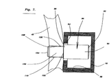
図7は、図1に示した1本のバーを1個のフープリングに取りつけた状態を部分的断面として示した拡大側面図である。
図8は、図7に示したものと同じような図ではあるが、本発明における異なる事例を示したものである。
図9は、図7に示したものと同じような図ではあるが、本発明における更に異なる事例を示したものである。
図10は、図4と同じような図ではあるが、乾燥機の中の下側位置に取りつけた2個のセグメントを示したものである。
なお、これらの図面中で使われる参照記号については、図と事例のすべてを通じ、同じ記号が同じ部品を参照するようにしている。
【0048】
図1は、本発明に基づき通常設計がなされた装置10の遠近図である。図1に示す装置10は、製紙機械における中空円筒型乾燥機14の内壁面12を通して、その外壁面16への熱エネルギーの移動を増加させるために提供されるものである。装置10においては、乾燥機14の中にその軸方向に沿って伸びるバー18〜35、すなわち、おのおのいずれも長方形の断面形状を有する複数本のバー18、19、20、21、22、23、24、25、26、27、28、29、30、31、32、33、34および35が取りつけられる。バー18〜35はいずれも、それぞれ互いに一定間隔をとって平行に並べられ、矢印36に示す方向、すなわち、乾燥機14の内壁面12に対して放射状に外側に向けて押さえつけられる。
【0049】
図2は、バー18〜35のうちの1本としてバー18に代表させて示した拡大断面図である。図2に示すように、バー18は乾燥機の軸方向に伸びる周縁材38により形成され、周縁材38の内側は中空となっている。
本発明に基づく更なる特定例では、バー18〜35はいずれも金属材料で製作される。更に特定するならば、バー18〜35はいずれも鉄鋼材料で製作される。本発明のある一事例では、この鉄鋼材料とは低炭素鋼のことであり、別のある好適例ではステンレス鋼のことである。
【0050】
更に加えて、バーの本数は12本から30本までの範囲内とし、より特定させるならば、15本から24本までの範囲内とする。
図1に示した例ではバーの本数は18本であるが、他の事例(ここでは図に示してはいない)では21本である。
【0051】
好ましくは、バー18〜35の本数は、乾燥機14の外径Dの3倍から4倍までの範囲内とする。ただし、ここで外径Dは図1に示すものとし、その単位はフィートで表わす。従って、例えば直径6フィートの乾燥機であれば、バーの本数は18本から24本ということになるであろう。また、各々のバーはいずれも、例えばバー18でいうならば、その隣りのバー19と互いに等しい間隔をとって並べられるのである。
【0052】
図2においてバー18で例示したように、おのおののバーはいずれも幅w 0.25インチ×奥行d 0.25インチから、幅w 1.50インチ×奥行d 1.50インチまでの範囲内の断面寸法を有する。
【0053】
図3は、図2に示したものと同じような図ではあるが、バー18aは正方形の断面形状を有するものである。
図2においてバー18で例示したように、おのおののバーはいずれも、外法幅w 、外法奥行d、内法幅w' 、内法奥行d'の各次元を有するものであるが、これらのバーの形状に関しては、
(1)バー18の全断面積は外法幅wと外法奥行dの積であり、
(2)周縁材38で囲まれた中空部の断面積は内法幅w’と内法奥行d’の積であり、それゆえに、
(3)バー18の金属部の断面積(図2においてハッチングで示した部分)は、全断面積(1)から周縁材38で囲まれた中空部の断面積(2)を減じた値となる。
ここでバー18の金属部の断面積(3)は全断面積(1)に対し、少なくともそれぞれ、25パーセント、50パーセント、あるいは75パーセント少ないケースのいずれかのケースの断面構造をとるものとする。
【0054】
図1に示すように、装置10にはまた通常設計で作られた機構40が含まれる。これはバー18〜35を、矢印36で示すように、乾燥機14の内壁面12に対して外方向に向けて押さえつける機構である。
更に特定させるならば、機構40には複数個のフープリング42、43、44、45および46が含まれる。これらのフープリングは、乾燥機14の中にその軸に沿い一定間隔をとって並べられ、いずれも乾燥機14の回転軸48に対し垂直に取りつけられる。
【0055】
図4は、フープリング42の拡大側面図である。図4に示すように、フープリング42は複数個のセグメント50、51および52から構成される。複数個のセグメント50〜52にはまず第一セグメント50が含まれるが、この第一セグメント50の一端には第一アーム54が設けられ、乾燥機14の内壁面12から乾燥機14の回転軸48の方角に向かって曲って伸びている。この第一アーム54には第一オリフィス56の孔が穿設されている。第一セグメント50のもう一方の一端には第二アーム58が設けられ、乾燥機14の内壁面12から乾燥機14の回転軸48の方角に向かって曲って伸びている。この第二アーム58には第二オリフィス60の孔が穿設されている。次に第二セグメント51の一端には第一リム62が設けられ、乾燥機14の内壁面12から乾燥機14の回転軸48の方角に向かって曲って伸びている。第一リム62には第一アパチュア64の孔が穿設されている。第二セグメント51のもう一方の一端には第二リム66が設けられ、乾燥機14の内壁面12から乾燥機14の回転軸48の方角に向かって曲って伸びている。第二リム66には第二アパチュア68の孔が穿設されている。
【0056】
図5は、図4に示した機構40の拡大図である。図5に示すように、通常設計により作られる調節具70には先端部72と末端部74がある。第一セグメント50の第二オリフィス60と第二セグメント51の第一アパチュア64の双方の孔に調節具70を貫通させ、双方のセグメントは調節具70によりひとつに連結される。これらの配置については、調節具70の先端部72を第二オリフィス60の孔に通し、調節具の末端部74を第一アパチュア64の孔に通すようにする。
【0057】
本発明の好適例では、図4に示すように、フープリング42〜46はいずれも3個のセグメント50〜52から構成される。
加えて図5に示すように、調節具70には先端部72と末端部74の間の一箇所に同心円状に拡がったツバ部76を設ける。調節具70をその末端部74のほうから第一アパチュア64の孔に挿し込んでいったとき、ツバ部76は第一リム62の面に掛り、これを押し支える役割を果たす。調節具70のツバ部76と末端部74との間にはガイド部78を設け、このガイド部78を末端部74から第一アパチュア64の孔に挿し込んでいく。調節具70のツバ部76と先端部72との間には雄ネジが切られたネジ部80を設け、このネジ部80は先端部72のほうから第二オリフィス60の孔に挿し込んでいく。ネジ部80には雌ネジが切られたナット状の可動部82を嵌め、第二オリフィス60の孔にネジ部80を挿し込んでいったとき、この可動部82が第二アーム58の面に掛り、これを押し支える役割を果たす。可動部82を廻らないように固定しておき、ネジ部80を廻していくと、可動部82とツバ部76はネジの働きにより互いに矢印84で示した方向に離れていくように動いていく。そうすると、第一セグメント50の第二アーム58は第二セグメント51の第一リム62から押し離されていき、フープリング42が拡大して、バー18〜35は、図1の矢印36 に示す方向に、乾燥機14の回転軸48から内壁面12の方向に向けてフープリング42により押しつけられるのである。
【0058】
図6は図5の矢印線6−6の方向から見た拡大図である。図6に示すように、ガイド部78には出力工具(図には示してない)のドライバ治具を受けるソケット86をつける。可動部82を廻らないように固定しておき、ドライバ治具を廻すと、ネジ部80は回転してフープリング42が締めあげられていく。
【0059】
図7は、1個のフープリングに取りつけられた1本のバーの部分的な断面を示した拡大側面図である。ただし、図7においては、それぞれを代表させてフープリング42とバー18についてのみあげてある。図7に示すように、装置10にはまた通常設計により作られるピン90が含まれる。これらのピンは、複数個のバー18〜35と複数個のフープリング42〜46を図1に示すように固定させるものである。
【0060】
ピン90には、図7に示すように、バー18の穴94に挿し込むための大径部位92と、フープリング42の穴108に挿し込むための小径部位100のふたつに分けられる。図7に示すように、ピン90の大径部位92は第一面96と第二面98で仕切られ、穴94には第一面96のほうから挿し込んでいく。挿し込まれた大径部位92はバーの周縁材38 の中にすっぽりと隠れ、第二面98が穴94の面上に掛かるようになる。
【0061】
図7に示すように、ピン90の小径部位100も第一面102と第二面104で仕切られ、この他に小径部位100の周囲の外表面106がある。小径部位100の第一面102は大径部位92の第二面98につながっている。
本発明の第一例では、フープリング42へのバー18の接続をやりやすくするため、ピンの小径部位100の外表面106には、穴108の内壁面と掛かる引掛り(barb)110を少なくとも1個以上つけておく。
【0062】
図8は、図7に示したものと同じような図ではあるが、本発明の第二例を示すものである。フープリング42へのバー18の接続をやりやすくするため、ピンの小径部位100の外表面106bには、穴108bの内壁面に固定させる溝ホゾ112を少なくとも1個以上つけておく。
【0063】
図9は、図7に示したものと同じような図ではあるが、本発明の第三例を示すものである。フープリング42へのバー18の接続をやりやすくするため、ピンの小径部位100cの外表面106cは、穴108cの内壁面とカシメ止められるようにぴったりと作っておく。
更に加えて、図7に示すように、大径部位92の直径を小径部位100の直径を大きくしておき、小径部位100をフープリング42の穴108に挿し込んだとき、ピン90の大径部位92はフープリング42の孔108に入らないようにしておく。
【0064】
また、大径部位92の直径は少なくとも0.25インチとし、好ましくはフープリングの厚さと等しい直径を有するものとする。
本発明には、製紙機械における円筒型乾燥機14の中に、長方形の断面形状を有する複数本の中空バー18〜35を、いずれも乾燥機14 の軸方向に互いに一定間隔をもって平行に並べれて取りつける組立方法が含まれている。この組立方法においては、まず最初にフープリングに組み立てる前のセグメント50、51および52にあらかじめピン90を挿し込んでおく。次の工程では、ピン90が挿し込まれたセグメント50〜52を乾燥機14 の内部に搬入する。その次の工程では、中空バー18〜35を乾燥機14の内部に搬入する。
【0065】
次に、セグメント50〜52に挿し込まれているピン90を、バー18のそれぞれ対応する箇所の穴94に挿し込んでいく。そうすると、例えばセグメント50にはこれに対応するバー18〜23がつながるようになり、セグメントとバーが一体のものとして組み立てられていく。更に、例えばセグメント50と51というような隣り合うセグメントの間に1個ずつ調整具70を取りつけていくと、これらはすべて一体となって1個フープリングを形成していくことになる。バー18〜35はこうして形づくられたフープリング42と乾燥機円筒14 の内壁面12 との間に挟み込まれる状態で取りつけられる。フープリング42を拡げてバー18〜35を乾燥機14の内壁面12に押しつけるためには、少なくとも1個以上の調節器70をドライバ治具で廻せるようにしておく。
【0066】
加えて、調節具による位置決め工程では、まずフープリング42の下側位置で隣り合うふたつのセグメント50、51の間に取りつけた調節具70で位置決め作業をしたのち、次に図4に示すように、下側位置のふたつのセグメント50、51と少なくとも1個以上ある上側位置のセグメント52の間に取りつけた調節具70’ および 70”での位置決め作業をしていき、最終的にフープリング42を完成させるのである。
【0067】
図10は、図4と同じような図ではあるが、乾燥機14の中の下側位置に取りつけたふたつのセグメント50と51とを示したものである。図10に示す更なる工程の中には、セグメント51を乾燥機14の内壁面12からある距離だけ引き離しておき、既に穴94に挿し込まれてあるピン90が抜けるのを防ぎながら、ピン90をそれぞれ対応する箇所のバーの穴94に近づけてピンの挿入をやりやすくするやり方が含まれている。
【0068】
本発明に基づく装置の操業では、直径5フィートの乾燥機には長方形の形状をした中空の鉄鋼製バー18本が取りつけられる。これらのバーはいずれも、紙の乾燥器円筒中に軸方向に向けて内壁面に近接するようにセットする。直径6フィートの乾燥機円筒ではバーの本数は21本となる。
【0069】
長方形の断面形状を有するこれらの中空バーの1本を図2に示す。好適例では、バーの棒状部分は乾燥機内壁に対して2個のフープリングで押さえつけられる。組み立てられたフープリングは、例えばフープリング42と43でいうと、これらはそれぞれ3個のセグメントから構成されるものであり、セグメント50と51、セグメント51と52、セグメント50と52の間にはそれぞれ1個ずつ調節具70が取りつけられる。おのおのの調整具にはネジが切られたナットまたは可動部が取りつけられており、これによってフープリングを締めつけていくのである。このナットは締め終ったのちにくさび止めか、あるいはバックアップジャムナットを使って緩まないようにする。このネジ付き締め具には、フープセグメントの両端部についているオリフィスやアパチュアの孔に通すため、十分な長さのガイド部またはヘッド部がとられるようになっている。また、この締め具の末端部にはソケットをつけて、手動式、空気圧式、または電動式のラチェット工具をこのソケットに嵌めて締め具を固く締まるまで廻せるようにしておく。好適例ではこの締め具はセグメントの湾曲による制限を受けない長さに抑えられるが、乾燥機の内径に相応した範囲で調節できる十分な長さが必要である。ネジ式締め具のひとつを図5に示す。
【0070】
好適例では、フープリングのセグメントは、ピンを用いて長方形のバーと固定されている。好適例では、フープの厚みは3/8インチであり、ピンの直径もまた3/8インチである。好適例では、これらのピンは長方形中空バーに挿し込む大径部位の直径は、セグメントに差し込む小径部位の直径よりも大きくしてある。大径部位の直径は小径部位の直径より1/16インチ大きいことが望ましい。これらのピンの1本を図7に示す。
好適例では、セグメントの穴に挿し込む小径部位の周囲の外表面には隆起あるいは引掛りをつけてある。乾燥機の内部でのバーの組立作業が終るまでの間、これらの隆起がピンをセグメントの穴にピンを固定させており、抜けないようにしてある。
【0071】
また、本発明にはバーの組立方法も含まれている。本発明に基づく次の手順でバーの組み立てをおこなうなら、バーの組み立てに要する時間は先行技術においておこなわれてきた方法で要していた時間のおよそ3分の1ほどに短縮される。
【0072】
本発明に基づく組立方法では、まず乾燥機の底部に沿わせて最初にふたつのセグメントをいずれも円周方向に向けて並べる。次にネジ式締め具をこれらふたつのセグメントの間に取りつけ、調節用ナットを締め具に嵌めていく。
更にこのとき、ふたつのセグメントの下にある隙間に長方形の中空バーを滑り落として、最底部の位置のバーから始めて一本ずつセグメントのピンをバーの所定の穴に挿し込んでいく。
下側位置に並べられたふたつのセグメントへのバーの取りつけが終ると、残っている上側位置用のセグメントをその下側で隣接するセグメントとネジ式締め具でつないで取りつける。残っているバーを一本ずつ上側位置用のセグメントの片側から始めて取りつけていき、最後のバーが取りつけ終るまでこれを繰り返す。
【0073】
次にネジ式締め具を締めていく。下側位置のふたつのセグメントから始める。おのおのの締め具は、手動式、電動式、あるいは空気圧式のラチェット工具を用いて締めつけ、このときナットは片開きレンチで押えておく。3個の締め具は各セグメント間の距離が等しくなるように調節され、最終的には決められた仕様通りに締めあげる。これで1個のフープリングの取りつけが完成する。この取りつけに要する時間はふたりの組立員のクルーでおよそ5〜10分間ほどである。
【0074】
【発明の効果】
本発明は、乾燥機の中から外壁面への熱移動を増加させる独創的な装置と提供するとともに、加えて、このような装置の組み立てに関する比較的簡便な方法をも提供するものである。
【図面の簡単な説明】
【図1】本発明に基づく装置の遠近図である。
【図2】図1に示した複数本のバーのうちの1本の断面を示した拡大図である。
【図3】図2と同じような図であるが、正方形の断面形状を有するバーについて示したものである。
【図4】図1に示した複数個のフープリングのうちの1個をフープリング42に代表させて示した拡大側面図である。
【図5】図4に示した調節具の箇所の機構を示した拡大図である。
【図6】図5における矢印線6−6の方向から見た拡大図である。
【図7】図1に示した1本のバーを1個のフープリングに取りつけた状態を部分的断面として示した拡大側面図である。
【図8】図7に示したものと同じような図ではあるが、本発明における異なる事例を示したものである。
【図9】図7に示したものと同じような図ではあるが、本発明における更に異なる事例を示したものである。
【図10】図4と同じような図ではあるが、乾燥機の中の下側位置に取りつけた2個のセグメントを示したものである。
【符号の説明】
10 装置
12 内壁面
14 乾燥機
16 外壁面
18、19、20、21、22、23、24、25、26、27、28、29、30、31、32、33、34、35 バー
38 周縁材
40 機構
42、43、44、45、46 フープリング
48 回転軸
50 第一セグメント
51 第二セグメント
52 第三セグメント
54 第一アーム
56 第一オリフィス
58 第二アーム
60 第二オリフィス
62 第一リム
64 第一アパチュア
66 第二リム
68 第二アパチュア
70 調節具
72 先端部
74 末端部
76 ツバ部
78 ガイド部
80 ネジ部
82 可動部
86 ソケット
90 ピン
92 大径部位
94、108 穴
96、102 第一面
98、104 第二面
100 小径部位
106 外表面
108 穴
110 引掛り
112 溝ホゾ[0001]
BACKGROUND OF THE INVENTION
The present invention relates to an apparatus for increasing the transfer of thermal energy through the inner wall surface of a hollow cylindrical dryer in a papermaking machine.
More specifically, the present invention relates to an apparatus for increasing the transfer of thermal energy through the inner wall surface of a hollow cylindrical dryer in a papermaking machine to the peripheral outer wall surface of the dryer.
[0002]
[Prior art]
Usually, in a papermaking machine, paper is dried by passing it over the outer wall surfaces of a plurality of cast iron cylinders that are steam heated. The diameter of such dryer cylinders is typically 4 feet, 5 feet, or 6 feet, with some modern dryers having a large diameter of 7 feet. The amount of steam in the cylinder is transferred to the paper through the outer shell of the dryer. As heat is transferred from hot steam to wet paper, the steam in the dryer becomes condensed water. The condensed water thus generated is extracted from the rotating cylinder through a rotary sealing device and through a siphon tube. The siphon pipe is connected to an external pipe or tank.
[0003]
In the case of low speed rotation, the condensed water remaining in the cylinder will become a puddle and accumulate at the bottom of the cylinder. This is a state called “ponding”. As the speed of the dryer is increased, the condensate in the puddle will begin to rotate with the rotation of the cylinder and will fall into this puddle in the middle of the rotation. This is a condition commonly known as “cascading”. In the case of high speed rotation, the condensate will go along the entire circumference of the dryer shell with the rotation of the cylinder. This is a state called “rimming”.
[0004]
In ponding and cascading conditions, the dryer is used to minimize the power required to rotate the dryer or to maximize the amount of heat transfer through the condensate water layer that rims around. It is common practice to design a siphon for condensate extraction to minimize the amount of condensate in it.
[0005]
However, in the case of high-speed rotation, even if the thickness of the remaining condensed water layer is very thin, its presence itself can be an extremely large thermal resistance for heat transfer from the steam to the dryer shell. In the case of high-speed rotation, the amount of water in the condensate layer that rims around is stagnant. Therefore, the heat transfer between the steam inside the condensate layer to be rimmed and the inner wall of the dryer shell is blocked. Serious heat transfer barrier.
[0006]
In order to increase the convective heat transfer rate through the rimming condensate water layer, rod-like parts have been developed that attach to the dryer cylinder to generate turbulent flow in the rimming condensate water layer. This bar-shaped part is called “dryer bar” or simply “bar”. The dryer bar is a set of a plurality of metal bar-like parts, and such a set is mounted in the dryer cylinder. These bars are attached in various ways to the inner wall of the dryer cylinder. These bars attempt to generate turbulence in the condensed water layer that forms and rims around each bar. When the turbulent flow in the water layer of the condensed water increases, the heat transfer rate increases. However, increasing the turbulent flow also makes the heat transfer from the dryer cylinder to the paper uniform.
[0007]
The dryer bar concept was first published by Barnscheidt and Staud in US Pat. No. 3,217,426. Later, in US Pat. No. 3,36724,094, Appel and Hong gave a special formula to predict the optimal amount of condensed water. A number of methods have been developed to attach these bars to the inner wall of the dryer. One of them is to hold the bar on the dryer shell surface using a series of magnets as described, for example, by Mathews in US Pat. No. 4,195,417. Another approach is to use a series of magnetic bars published by Wedel in US Pat. No. 4,486,962. Various types of springs and pins are used in the methods published by Kraus (US Pat. No. 3,808,700), Schiel (US Pat. No. 4,267,644), and Schiel (US Pat. No. 4,282,656).
[0008]
[Problems to be solved by the invention]
All these bars used in the prior art are made of metal (usually "not hollow") (usually made of mild steel but often made of stainless steel in a corrosive atmosphere). . The bars used in the commercial case are of dimensions from 0.25 "x 0.25" to 0.5 "x 0.75" and the cross-sectional shape is square or rectangular. For bar cross-sectional shape and dimensions, the number of rows of bars in the dryer, the amount of condensed water expected to rim in the dryer, the cost of the bar, the difficulty of bending the bar, and the handling of the bar during assembly Each element of ease is selected as an evaluation criterion.
[0009]
Since the bar with a large cross section is heavy, the assembly work is difficult. It is particularly difficult to assemble in a conventional paper dryer with a diameter of only 4-6 feet. On the other hand, a bar with a small cross-section is easy to handle, but it is difficult to obtain a structural bend that resists tumbling of condensed water in the dryer for a long period of time, and it is difficult to bend immediately. There is.
[0010]
In general, a papermaking dryer is provided with an opening / closing port on a cylindrical side. These opening / closing ports (manholes) are for internal inspection of the dryer cylinder and assembling a siphon device. On the other hand, since it is very difficult to fully open and close both ends of the dryer cylinder, such work should be avoided as much as possible. Therefore, the member tools necessary for assembling the dryer bar must be brought from the manhole so that it can also be assembled inside the conventional dryer cylinder. For this reason, the design of the dryer bar support device is limited in size.
[0011]
Furthermore, the latest paper machines produce paper up to 400 inches wide at a high speed of 6,000 feet per minute. Such a high-speed papermaking machine can produce as much as 1,000 tons of paper per day. In such high speed papermaking machines, the cost loss from shutting down to assemble the dryer bar often exceeds $ 15,000 per hour. If the assembly time of the dryer bar in the conventional dryer cylinder can be shortened, the operation stop time of the papermaking machine can be greatly shortened. Despite so many incentives to reduce assembly time, in the prior art, the assembly time for dryer bars is still typically 1.5 to 2.5 hours per cylinder. . In the prior art, it can be said that the assembly time has not been substantially reduced.
[0012]
In most of the prior art, a method of pressing the dryer bar against the inner wall surface of the cylinder of the dryer outer shell using a “clamp ring” assembled from a plurality of arc-shaped components has been adopted. In order to securely attach the dryer bar to the dryer shell, it must be pressed against the inner wall of the dryer shell with a strong ring. In order to obtain a strong force to press against the inner wall with the ring, the prior art design incorporates various systems into the flange of the arcuate component to generate a force that causes the arcuate components to be pulled apart from each other. I came.
[0013]
One such system is a combination of a tightening screw and a lock nut. Tightening the tightening screw with two single-ended wrench is a time-consuming task. Since the tightening screw has high rigidity, as long as the tightening screw is used, it is difficult to give the tightening ring enough elasticity to allow a difference in thermal expansion from the outer shell of the dryer. Without a method that can tolerate the difference in thermal expansion, distortion in the tightening screw, distortion in the arcuate parts, and distortion occurring on the dryer shell will increase. This causes deformation of the fastener ring and the like, and may cause loosening in the long term.
[0014]
In a more devised design, various types of springs are used where the arcuate components are connected. As the spring, either a coil spring, a cylinder spring, or a Belleville washer is used. Since these springs function even when the dryer is heated, the force with which the arc-shaped structural member presses the bar is maintained as it is. However, it takes a long working time to assemble these complex systems. Since complex springs are assembled, the number of parts to be handled is increased, and various types of dedicated tools are required in addition to ordinary tools.
[0015]
In the prior art, the bars are screwed one by one to the arcuate component so that the bars do not shift in the circumferential direction of the cylinder. The bar is usually fixed to the component by a small screw type fastener (round screw). In order to prevent these small screw type fasteners from loosening in the dryer cylinder, some kind of locking mechanism that can properly lock the screws is required. The lock mechanism that has been used in the prior art includes a split washer, a Belleville washer, an automatic lock with a brim (WhizLock), and a groove hozo. While working inside the dryer cylinder, it is difficult to install these screw-type fasteners side by side. It is difficult to fit the screw into the screw hole formed in the bar, and the tapping screw is fragile. Small diameter pins are difficult to set, fragile and loose in the dryer.
[0016]
[Means for Solving the Problems]
The present invention provides a method and apparatus for improving the drying capacity of a steam heated cylinder, particularly a cylindrical dryer in a papermaking machine. In this apparatus, a plurality of bars are used which are arranged close to the cylindrical inner wall of the outer shell of the dryer and arranged in parallel along the axial direction of the dryer. If the present invention is further specified, the apparatus itself with a hollow bar having a rectangular cross-sectional shape, a mounting method for attaching these bars to the dryer outer shell, and the cylinder of the dryer outer shell. And an assembling method for assembling within the interior. The bar mounting method mentioned here includes a tightening system for tightening the bar. Some tightening systems that tighten bars include a plurality of arcuate components (hereinafter called “hoop segments” or simply “segments”) connected to each other by special fasteners. ), Clamp ring (hereinafter referred to as “hoop” or “hoop ring”), multiple bars connected to a segment by special pins, and their assembly It includes multiple elements such as the unique shape of the bar that can reduce the time and amount of work required. These elements function intertwined with each other.
[0017]
The dryer bar according to the present invention has a structure that is harder to bend than those of conventional shapes, and is lighter in weight. With the device according to the invention, the assembly time can be reduced to about one third. The apparatus according to the present invention is low in construction cost, and if the dryer bar having the shape according to the present invention is used, the heat transfer rate should be equal to or higher than that of the prior art dryer bar. Can do.
[0018]
In order to reduce the weight of the dryer bar, the bar according to the invention is a hollow tube having a rectangular shape. Due to the shape of the tube, it is lighter and harder to bend than prior art bars. This makes the handling of the bar much easier during assembly and at the same time reduces the difficulty of bending the bar due to the impact of tumbling the condensed water.
[0019]
For example, a steel bar having a cross-sectional shape of 0.5 inch x 0.75 inch and a length of 6 feet of muk (meaning "not hollow") weighs 7.6 pounds. Thus, to assemble 18 rows of bars, the assembly crew must carry a total weight of 138 pounds. However, the bar according to the present invention (preferred size is 0.75 "x 1.00" in cross section and 0.065 "thick) is only 4.3 pounds, so the same 18 rows To assemble the bar, the assembly crew only needs to carry a bar weighing only 77 pounds.
[0020]
Moreover, the bar of the present invention is remarkably improved in terms of difficulty in bending. The moment of inertia of the prior art bar described above is 0.008 in diameter. 4 , Circumferential direction 0.018 in 4 It is. On the other hand, in comparison with this, the moment of inertia of the bar of the present invention is 0.018 in diameter direction. 4 , Circumferential direction 0.029 in 4 It is. That is, 130% is less likely to bend in the diameter direction, and 60% is less likely to bend in the circumferential direction. All of these things come from light weight.
[0021]
In the present invention, as in most of the prior arts, a method of using a plurality of hoop segments and pressing a bar against the inner wall surface of the dryer outer shell is employed. In order to firmly hold the bar against the cylindrical inner wall of the dryer outer shell, these hoop segments are tightened with a unique screw-type fastener and pressed against the inner wall of the dryer outer shell. . This fastener system consists of bolts and nuts. The front end and the end of the fastener are passed through holes formed at both ends of the hoop segment. The fasteners are held properly during assembly and operation. A socket for turning the screw is attached to the end of the fastener, but it may be a hexagonal outer shape. Because the part that looks like the arm at the end of the adjacent hoop segment is pushed in with a nut, it is tightened by turning the fastener with a screw using a manual or automatic (electrical or pneumatic drive) ratchet tool is there. This significantly speeds up the assembly process.
[0022]
The bar of the present invention is secured to the hoop segment by using a relatively large diameter pin. Prior to assembling the bar, these pins are pre-attached to the hoop segment. It took much time to attach the conventional pins and screw-type fasteners because it was necessary to install them one by one inside the dryer cylinder. On the other hand, in the present invention, since the pin is attached to the hoop segment in advance outside the dryer cylinder, the working time for this inside the dryer cylinder is not required at all. To prevent the pins from falling out of the hoop segment, these pins have shoulders with different diameters so that they will not come out even if they are used for many years.
[0023]
The normal thermal expansion difference that occurs between the dryer shell and the assembled bar structure is absorbed by the radial flexibility of the rectangular hollow tubular bar. The bendability of the rectangular hollow tubular bar in the radial direction works with the bendability of the hoop segment, and the assembled bar structure absorbs the differential thermal expansion in the normal direction. There is no need to use complex differential thermal expansion absorption systems such as springs and universal joints.
[0024]
Since the bar of the present invention is hollow, its weight is light compared to the outer dimensions. That is, the total cross-sectional area of the hollow tubular bar is larger than the cross-sectional area of the bar having the same weight (meaning “not hollow”). This makes it possible to freely select a bar having a large cross-sectional dimension that optimizes the generation of turbulent flow in the water layer of the condensed water to be rimmed and obtains the maximum heat transfer rate.
[0025]
In addition, by adopting a hollow tubular bar, it may be possible to use a stainless steel as a bar material in a dryer in which corrosion becomes a problem without damaging the economy. Because stainless steel is expensive, it is usually not possible to use stainless steel as a material for the bar of muk (meaning “not hollow”), except in special cases where it is acceptable at high cost. However, since the hollow bar has a smaller member cross section, if it can be manufactured at a competitive cost compared to Muku's (not “hollow”) mild steel bar, stainless steel can be used instead of mild steel. It can also be used.
[0026]
As described so far, the first feature of the present invention is to provide an apparatus for increasing heat energy transfer through the inner wall surface of a hollow cylindrical dryer in a papermaking machine, which has been provided by the prior art. It provides an improvement measure that greatly exceeds the performance.
[0027]
Another feature of the present invention is to provide an apparatus for increasing the heat energy transfer through the inner wall of a hollow cylindrical dryer in a papermaking machine. It is to be easier to manufacture than the one.
[0028]
A further feature of the present invention is to provide an apparatus for increasing the transfer of thermal energy through the inner wall of a hollow cylindrical dryer in a papermaking machine. It is to be able to be constructed at a lower cost than that of technology.
[0029]
Another feature of the present invention is to provide a device for increasing the transfer of thermal energy through the inner wall of a hollow cylindrical dryer in a papermaking machine, but it is particularly assembled on site. It should be easy.
[0030]
Other features and inventive steps of the present invention will be readily apparent to those skilled in the art when considering the detailed description of the preferred embodiments of the present invention set forth herein.
DETAILED DESCRIPTION OF THE INVENTION
The present invention relates to an apparatus for increasing the transfer of thermal energy through the inner wall surface of a hollow cylindrical dryer in a papermaking machine to its surrounding outer wall surface. This apparatus is provided with a plurality of bar-shaped parts (hereinafter referred to as “bars”) having a rectangular cross-sectional shape, and these bars all extend in the dryer in the axial direction. All of these bars are arranged in parallel with each other at regular intervals, and are pressed radially outward against the inner wall surface of the dryer cylinder. Moreover, all of these bars are formed of a peripheral material extending along the axial direction of the dryer, and the inside of the peripheral material is hollow.
[0031]
In a further specific example according to the invention, these bars are both made of a metallic material. If further specified, both of these bars are made of steel material. In one case, the steel material is low carbon steel, and in another preferred case is stainless steel.
[0032]
In addition, the number of these bars is in the range of 12 to 30, and if more specific, the number of bars is in the range of 15 to 24.
In some cases, the number of these bars is 18; in other cases, the number of bars is 21.
Preferably, the number of these bars is in the range of 3 to 4 times the outside diameter of the dryer. At this time, the unit of the outer diameter is expressed in feet. In addition, all of these bars are arranged in parallel with each other at regular intervals.
[0033]
The external dimensions of these bars all range from 0.25 inches wide x 0.25 inches deep to 1.50 inches wide x 1.00 inches deep. In one example, these bars all have a square cross-sectional shape.
[0034]
In addition, each of these bars has dimensions of outer width, outer depth, inner width, and inner depth, but regarding the shape of these bars:
(1) The total cross-sectional area of one bar is the product of the outer width and outer depth,
(2) The cross-sectional area of the hollow portion of one bar is the product of the inner width and the inner depth. therefore,
(3) The cross-sectional area of the metal portion of one bar is a value obtained by subtracting the cross-sectional area (2) of the hollow portion from the total cross-sectional area (1).
Here, the cross-sectional area (3) of the metal part is assumed to be the cross-sectional structure of any one of the cases of at least 25%, 50%, or 75% less than the total cross-sectional area (1). .
[0035]
This device includes a mechanism for pressing each of these bars radially outward against the inner wall of the dryer cylinder.
More specifically, this mechanism includes a plurality of fastening rings (hereinafter referred to as “hoop rings”). These hoop rings are all arranged in the dryer at regular intervals along the axial direction, and are attached perpendicularly to the rotating shaft of the dryer.
[0036]
In addition, each of these hoop rings is composed of a plurality of arcuate components (hereinafter referred to as “hoop segments” or simply “segments”). . The first one of the plurality of segments is a “first segment”. One end of the first segment is a first arm portion (hereinafter referred to as “first arm”) that extends in a direction toward the rotation axis from the inner wall surface of the dryer, and the first arm has a hole. It has been drilled. This hole will be referred to as the “first orifice”. The other end of the first segment is also a second arm portion (hereinafter referred to as a “second arm”) that extends in a direction from the inner wall surface of the dryer toward the rotation axis, and has a hole in the second arm. Is drilled. This hole will be referred to as a “second orifice”. The next one of the plurality of segments is a “second segment”. One end of the second segment is also a first arm portion (hereinafter referred to as “first rim”) that extends in a direction from the inner wall surface of the dryer toward the rotation axis. A hole is also formed in the first rim, and this hole is referred to as a “first aperture”. The other end of the second segment is also a second arm portion (hereinafter referred to as “second rim”) that extends in a direction from the inner wall surface of the dryer toward the rotation axis. A hole is also formed in the second rim, and this hole is referred to as a “second aperture”.
[0037]
Further, both the hole of the second orifice of the first segment and the hole of the first aperture of the second segment are penetrated by one “adjustment tool” having a rod shape, and both the segments are moved by this adjustment tool. Connect to one. This adjuster has a "tip" and a "end", and their arrangement is such that the tip of the adjuster passes through the second orifice and the end passes through the first aperture. .
[0038]
In a preferred embodiment of the present invention, one hoop ring is assumed to be composed of three segments.
In addition, the adjustment tool is provided with a “flank” that extends concentrically at one location between the tip and the end. When the adjustment tool is inserted into the hole of the first aperture from the end portion, the flange portion is hooked on the surface of the first rim and plays a role of pushing and supporting it. A “guide portion” is defined between the flange portion and the end portion of the adjustment tool. The guide portion is inserted from the end portion through the hole of the first aperture. A “screw part” in which a male screw is cut is formed between the flange part and the tip part of the adjustment tool, and this screw part is inserted into the hole of the second orifice from the tip part. A nut-like “movable part” with a female thread cut into the threaded part is fitted into the threaded part. When the screw portion is inserted into the hole of the second orifice, the nut-like movable portion is hooked on the surface of the second arm and plays a role of pushing and supporting it. When the nut portion is fixed so as not to rotate and the screw portion is rotated, the movable portion and the flange portion are moved away from each other by the action of the screw. Then, the second arm of the first segment is pushed away from the first rim of the second segment, and the hoop ring expands. As the hoop ring expands, each bar is pressed from the rotating shaft of the dryer toward the direction of the inner wall surface.
[0039]
The guide part is provided with a “socket” for receiving a driver jig of the output tool. Instead of the socket, the guide portion may have a hexagonal outer shape so that the driver jig of the output tool can be fitted therein.
[0040]
This device also uses a pin that connects both the bar and the hoop ring at all points where one bar and one hoop ring intersect. This pin is inserted and connected to both the hoop ring and the hole previously drilled in the bar. The bar is secured to the hoop ring by such pins.
[0041]
More specifically, this pin has a “large diameter part” for insertion into a hole previously drilled in the bar and a “small diameter part” for insertion into a hole previously drilled in the hoop ring. There is a step between the diameters of both parts. The large-diameter portion is partitioned by the first surface and the second surface, and is inserted into the hole of the bar from the first surface. The large-diameter portion inserted into the bar is completely hidden in the peripheral material of the bar, and the second surface thereof hangs on the surface of the hole of the bar. On the other hand, the small-diameter portion is also partitioned by the first surface and the second surface in the same manner as the large-diameter portion, and there is an outer surface in contact with the inner wall surface of the hole of the hoop ring around the small-diameter portion. The first surface of the small diameter portion is connected to the second surface of the large diameter portion.
[0042]
In the first example of the present invention, in order to facilitate the connection of the bar to the hoop ring, at least one hook (barb) that hangs with the inner wall surface of the hole of the hoop ring is attached to the outer surface of the small diameter portion. .
In the second example of the present invention, in order to facilitate the connection of the bar to the hoop ring, at least one groove lock that is fixed to the inner wall surface of the hole of the hoop ring is attached to the outer surface of the small diameter portion. Keep it.
In the third example of the present invention, in order to facilitate the connection of the bar to the hoop ring, the outer surface of the small-diameter portion is made tightly so as to be caulked with the inner wall surface of the hole of the hoop ring. deep.
In addition, by making the diameter of the large diameter part larger than the diameter of the small diameter part and making a step, when the small diameter part is inserted into the hole of the hoop ring, the large diameter part does not enter the hole of the hoop ring. Keep it away.
[0043]
The diameter of the large-diameter portion is at least 0.25 inches or more, preferably equal to the thickness (width) of the hoop ring. In one particular example, the diameter of the large diameter portion is 0.375 inches.
[0044]
In the present invention, a plurality of hollow bars having a rectangular cross-sectional shape are assembled in a dryer cylinder of a papermaking machine by arranging them in parallel with each other along the axial direction of the dryer. An assembly method is included. In this method, first of all, pins are inserted into all the holes of the segment yet to be assembled into the hoop ring. In the next step, the segment with the pin inserted is carried into the dryer cylinder. In the next step, the hollow bar is carried into the dryer cylinder.
[0045]
Next, it moves to the work inside the dryer cylinder. In the operation inside the dryer cylinder, the pins inserted into the segments are inserted into the corresponding holes of the bar. When this operation is finished, a segment and a plurality of bars corresponding to it are connected for the first time. When one adjuster is installed between adjacent segments, they all function as one body and are formed as a single hoop ring. The bar is sandwiched between the hoop ring thus formed and the cylindrical inner wall surface of the dryer. In order to expand the hoop ring and press the bar against the inner wall surface of the dryer cylinder, at least one adjustment tool is used.
[0046]
In the positioning step using the adjusting tool, the positioning work using the adjusting tool is first completed between two adjacent segments at the lower position of the hoop ring, and then the lower position segment and the segment having at least one upper position Positioning work with the adjuster between the two. This completes the hoop ring.
Also, in the process of inserting the large diameter part of the pin inserted into the segment into the corresponding hole of the bar, the segment is once separated from the inner wall surface of the dryer cylinder by a certain distance and already inserted into the segment. While preventing the rare pin from coming off, the pin is brought close to the corresponding hole in the bar to make it easier to insert the pin.
[0047]
DETAILED DESCRIPTION OF THE INVENTION
Numerous modifications and changes in the present invention will be readily apparent to those skilled in the art when considering the accompanying drawings and the following detailed description showing the preferred embodiments of the present invention. However, such modifications and changes are included in the concept of the present invention and the claims of the present invention as defined by the claims of the claims of the present specification.
FIG. 1 is a perspective view of an apparatus according to the present invention.
FIG. 2 is an enlarged view showing a cross section of one of the plurality of bars shown in FIG.
FIG. 3 is a view similar to FIG. 2, but showing a bar having a square cross-sectional shape.
FIG. 4 is an enlarged side view showing one of the plurality of hoop rings shown in FIG.
FIG. 5 is an enlarged view showing a mechanism of a portion of the adjustment tool shown in FIG.
FIG. 6 is an enlarged view seen from the direction of the arrow line 6-6 in FIG.
FIG. 7 is an enlarged side view showing, as a partial cross section, a state where one bar shown in FIG. 1 is attached to one hoop ring.
FIG. 8 is a diagram similar to that shown in FIG. 7, but shows a different case in the present invention.
FIG. 9 is a view similar to that shown in FIG. 7, but shows a further different case in the present invention.
FIG. 10 is a view similar to FIG. 4, but showing two segments attached to the lower position in the dryer.
In addition, about the reference symbol used in these drawings, the same symbol refers to the same component through all figures and examples.
[0048]
FIG. 1 is a perspective view of a
[0049]
FIG. 2 is an enlarged cross-sectional view represented by the
In a further specific example according to the invention, the
[0050]
In addition, the number of bars should be in the range of 12 to 30 and more specifically in the range of 15 to 24.
In the example shown in FIG. 1, the number of bars is 18, but in other cases (not shown here), there are 21 bars.
[0051]
Preferably, the number of
[0052]
As illustrated by
[0053]
FIG. 3 is a view similar to that shown in FIG. 2, but the bar 18a has a square cross-sectional shape.
As illustrated by the
(1) The total cross-sectional area of the
(2) The cross-sectional area of the hollow portion surrounded by the
(3) The cross-sectional area of the metal part of the bar 18 (the part indicated by hatching in FIG. 2) is a value obtained by subtracting the cross-sectional area (2) of the hollow part surrounded by the
Here, the cross-sectional area (3) of the metal portion of the
[0054]
As shown in FIG. 1, the
More specifically, the
[0055]
FIG. 4 is an enlarged side view of the
[0056]
FIG. 5 is an enlarged view of the
[0057]
In the preferred embodiment of the present invention, as shown in FIG. 4, the hoop rings 42 to 46 are each composed of three
In addition, as shown in FIG. 5, the
[0058]
FIG. 6 is an enlarged view seen from the direction of the arrow line 6-6 in FIG. As shown in FIG. 6, the
[0059]
FIG. 7 is an enlarged side view showing a partial cross section of one bar attached to one hoop ring. However, in FIG. 7, only the
[0060]
As shown in FIG. 7, the
[0061]
As shown in FIG. 7, the small-
In the first example of the present invention, in order to facilitate the connection of the
[0062]
FIG. 8 is a diagram similar to that shown in FIG. 7, but shows a second example of the present invention. In order to facilitate the connection of the
[0063]
FIG. 9 is a view similar to that shown in FIG. 7, but shows a third example of the present invention. In order to facilitate the connection of the
In addition, as shown in FIG. 7, when the diameter of the large-
[0064]
The diameter of the
In the present invention, a plurality of
[0065]
Next, the
[0066]
In addition, in the positioning step using the adjuster, first, positioning is performed with the
[0067]
FIG. 10 is a view similar to FIG. 4 but shows two
[0068]
In the operation of the apparatus according to the invention, 18 rectangular steel bars are attached to a 5 foot diameter dryer. All of these bars are set in the paper dryer cylinder so as to be close to the inner wall surface in the axial direction. In a dryer cylinder having a diameter of 6 feet, the number of bars is 21.
[0069]
One of these hollow bars having a rectangular cross-sectional shape is shown in FIG. In a preferred embodiment, the bar portion of the bar is pressed against the dryer inner wall with two hoop rings. The assembled hoop rings are, for example, hoop rings 42 and 43, which are each composed of three segments. Between the
[0070]
In a preferred embodiment, the hoop ring segments are secured to the rectangular bar using pins. In the preferred embodiment, the hoop thickness is 3/8 inch and the pin diameter is also 3/8 inch. In a preferred embodiment, the diameter of the large diameter portion of these pins inserted into the rectangular hollow bar is larger than the diameter of the small diameter portion inserted into the segment. The diameter of the large diameter part is preferably 1/16 inch larger than the diameter of the small diameter part. One of these pins is shown in FIG.
In the preferred embodiment, the outer surface around the small diameter section that is inserted into the hole in the segment is raised or hooked. Until the assembly of the bar inside the dryer is finished, these ridges keep the pins in the segment holes and prevent them from coming off.
[0071]
The present invention also includes a method for assembling the bar. If the bars are assembled according to the following procedure according to the present invention, the time required for assembling the bars is reduced to about one third of the time required for the methods performed in the prior art.
[0072]
In the assembling method according to the present invention, first, the two segments are first arranged in the circumferential direction along the bottom of the dryer. Next, a screw-type fastener is attached between the two segments, and an adjusting nut is fitted into the fastener.
Further, at this time, the rectangular hollow bar is slid down into the gap under the two segments, and the segment pins are inserted into the predetermined holes of the bar one by one, starting from the bar at the bottom.
When the attachment of the bar to the two segments arranged in the lower position is finished, the remaining upper position segment is attached to the adjacent lower segment with a screw type fastener. Install the remaining bars one by one, starting from one side of the segment for the upper position, and repeat until the last bar has been installed.
[0073]
Next, tighten the screw type fastener. Start with two segments in the lower position. Each fastener is tightened using a manual, electric, or pneumatic ratchet tool, and at this time, the nut is held with a one-sided wrench. The three fasteners are adjusted so that the distances between the segments are equal, and finally the fasteners are tightened according to the determined specifications. This completes the installation of one hoop ring. This installation takes about 5-10 minutes for the crew of the two assemblers.
[0074]
【The invention's effect】
The present invention provides an ingenious device that increases heat transfer from the dryer to the outer wall surface, and additionally provides a relatively simple method for assembling such a device.
[Brief description of the drawings]
FIG. 1 is a perspective view of an apparatus according to the present invention.
FIG. 2 is an enlarged view showing a cross section of one of the plurality of bars shown in FIG. 1;
FIG. 3 is a view similar to FIG. 2, but showing a bar having a square cross-sectional shape.
4 is an enlarged side view showing one of the plurality of hoop rings shown in FIG.
5 is an enlarged view showing a mechanism of a portion of the adjustment tool shown in FIG.
6 is an enlarged view seen from the direction of arrow line 6-6 in FIG.
7 is an enlarged side view showing, as a partial cross-section, a state where one bar shown in FIG. 1 is attached to one hoop ring. FIG.
8 is a view similar to that shown in FIG. 7, but showing a different case in the present invention.
FIG. 9 is a view similar to that shown in FIG. 7, but showing a further different case in the present invention.
FIG. 10 is a view similar to FIG. 4 but showing two segments attached to the lower position in the dryer.
[Explanation of symbols]
10 devices
12 inner wall
14 Dryer
16 Exterior wall
18, 19, 20, 21, 22, 23, 24, 25, 26, 27, 28, 29, 30, 31, 32, 33, 34, 35 bar
38 Peripheral material
40 Mechanism
42, 43, 44, 45, 46 Hoop Ring
48 Rotating shaft
50 First segment
51 Second segment
52 Third segment
54 First arm
56 First orifice
58 Second arm
60 Second orifice
62 First rim
64 First Aperture
66 Second rim
68 Second Aperture
70 Adjuster
72 Tip
74 Terminal
76 head
78 Guide section
80 Screw part
82 Moving parts
86 socket
90 pins
92 Large diameter part
94, 108 holes
96, 102 First side
98, 104 Second side
100 Small diameter part
106 outer surface
108 holes
110 catch
112 groove
Claims (32)
当該バーはいずれも乾燥機中にその軸方向に沿って伸び、それぞれ互いに一定間隔をとって平行に並べられ、乾燥機の内壁面に対してそれぞれ放射状に外側に向けて押さえつけられる;
当該バーはいずれも周縁材で囲われた形状で、内側は中空となっており、この周縁材は乾燥機の軸方向に伸びている;
当該機構は次のものから構成される:
乾燥機の中に軸方向に沿って一定間隔をとって並べられ、乾燥機の回転軸に垂直に取りつけられた複数個のフープリング;
当該各フープリングには、いずれも第一セグメントと第二セグメントとを含む複数個のセグメントが含まれる:
当該第一セグメントには次のものが含まれる:
乾燥機の内壁面の方角から乾燥機の回転軸の方角に曲って伸びる第一アーム、当該第一アームには第一オリフィスが穿設されている;
乾燥機の内壁面の方角から乾燥機の回転軸の方角に曲って伸びる第二アーム、当該第二アームには第二オリフィスが穿設されている;
当該第二セグメントには次のものが含まれる:
乾燥機の内壁面の方角から乾燥機の回転軸の方角に曲って伸びる第一リム、当該第一リムには第一アパチュアが穿設されている;
乾燥機の内壁面の方角から乾燥機の回転軸の方角に曲って伸びる第二リム、当該第二リムには第二アパチュアが穿設されている;
先端部と末端部を有する調節具、当該調節具は、第一セグメントの第二オリフィスと第二セグメントの第一アパチュアに通すものである、ただし、第二セグメントの孔には調節具の先端部側を通し、第一アパチュアには調節具の末端部側を通す;
当該調節具には更に次のものが含まれる:
調節具の先端部と末端部との間に設けた同心円状に拡がる形状のツバ部、当該ツバ部は調節具を末端部側から第一アパチュアに通していくと、第一リムの面に当ってこれを押し支える;
ツバ部と調節具の末端部間に伸びるガイド部、当該ガイド部は調節具の末端部側から第一アパチュアに通していく;
ツバ部と調節具の先端部間に伸びるネジ部、当該ネジ部は第二オリフィスに通していく;
ネジ部とネジが噛み合う可動部、ネジ部を第二オリフィスに通していくと、当該可動部は第二アームの面に当ってこれを押し支えるものであり、可動部を廻らないように固定してネジ部を廻していくと、可動部とツバ部はネジの働きで互いに離れていき、それで第一セグメントの第二アームは第二セグメントの第一リムから押し離されていくのでフープリングが拡大していき、バーはいずれもフープリングにより乾燥機の回転軸から乾燥機の内壁面の方向に対して外側に向けて押さえつけられる。An apparatus for increasing the transfer of heat energy to the surrounding outside wall of the dryer through the inner wall surface of the hollow cylindrical dryer of a papermaking machine, the apparatus includes a plurality book with a rectangular cross-sectional shape bar, A mechanism for pressing each of the bars radially outward against the inner wall of the dryer cylinder :
Any person said bar extends along the axial direction of the dryer, are respectively arranged in parallel taking a certain distance from each other, they are pressed outward radially respectively dryer inner wall surface of the;
Each of the bars has a shape surrounded by a peripheral material and is hollow inside, and the peripheral material extends in the axial direction of the dryer;
The mechanism consists of:
A plurality of hoop rings arranged at regular intervals along the axial direction in the dryer and mounted perpendicular to the rotating shaft of the dryer;
For in each hoop ring are all Ru includes a plurality of segments including a first segment and the second segment:
To those said first segment Ru include the following:
The first arm from direction of the inner wall surface of the dryer extending bent in direction of the rotational axis of the dryer, the first orifice or the said first arm is bored;
Second arm from direction of the inner wall surface of the dryer extending bent in direction of the rotational axis of the dryer, said the second arm second orifice or is bored;
To those said second segment Ru include the following:
The first rim from direction of the inner wall surface of the dryer extending bent in direction of the rotational axis of the dryer, the said first limb is first Apachu A is bored;
Second rim from the direction of the inner wall surface of the dryer extending bent in direction of the rotational axis of the dryer, the said second limb second Apachu A is bored;
Adjuster having a tip portion and a distal portion, said adjusting means are those passed through a second orifice or the first Apachu A second segment of the first segment, provided that the hole of the second segment tone Fushigu the through-edge portion side, to passing the end-side end of the first Apachu a tone Fushigu;
The said adjuster Ru include those further follows:
Flange of the concentrically spreads shape provided between the previous end and the end edge portion of the tone Fushigu, when the flange portion goes through a first Apachu A end ends side or we temper Fushigu, Hit the surface of the first rim to support it;
Guide portion extending between the ends end of tool bar section and tone Fushigu, the guide portion goes through the end side or we first Apachu A end regulating Fushigu;
Threaded portion extending between the previous end of the tool bar portion and tone Fushigu, the threaded portion goes through a second orifice or;
Screw portion and a movable portion which screw engages, when the screws portion going through the second orifice or, the movable portion is intended to support pushing it hitting the surface of the second arm, not Megura the moving parts fixed as you turn the screw portion so, moving parts and the tool bar section move further away from each other by the action of the screw, it in the second arm of the first segment pushes the first rim of the second segment isolated by going to in full Puringu continue to expansion, it is pressed outwardly to the direction of the inner wall surface of the dryer from the rotation axis of the dryer by also full Puringu any bar.
(1)1本のバーの全断面積は、外法幅と外法奥行の積であり、
(2)1本の中空部の断面積は、内法幅と内法奥行の積であり、
(3)1本の金属部の断面積は、当該全断面積(1)から当該中空部の断面積(2)を減じた値となり、
そこで、当該金属部の断面積(3)は、全断面積(1)より少なくとも25パーセント少ない断面構造を有する請求項2記載の装置。Each of the bars has dimensions of outer width, outer depth, inner width, inner depth.
(1) The total cross-sectional area of one bar is the product of the outer width and outer depth,
(2) 1 cross-sectional area of the hollow portion in the present is the product of the clear width and clear width depth,
(3) 1 cross-sectional area of the metallic portion of this becomes a value obtained by subtracting the cross-sectional area (2) of the hollow portion from the total cross-sectional area (1),
Therefore, the cross-sectional area (3) of the metal part, device 請 Motomeko 2 wherein that having a least 25% less cross sectional structure than the total cross-sectional area (1).
(1)1本のバーの全断面積は、外法幅と外法奥行の積であり、
(2)1本の中空部の断面積は、内法幅と内法奥行の積であり、
(3)1本の金属部の断面積は、当該全断面積(1)から当該中空部の断面積(2)を減じた値となり、
そこで、当該金属部の断面積(3)は、全断面積(1)より少なくとも50パーセント少ない断面構造を有する請求項2記載の装置。Each of the bars has dimensions of outer width, outer depth, inner width, inner depth.
(1) The total cross-sectional area of one bar is the product of the outer width and outer depth,
(2) 1 cross-sectional area of the hollow portion in the present is the product of the clear width and clear width depth,
(3) 1 cross-sectional area of the metallic portion of this becomes a value obtained by subtracting the cross-sectional area (2) of the hollow portion from the total cross-sectional area (1),
Therefore, the cross-sectional area (3) of the metal part, device 請 Motomeko 2 wherein that having a least 50% less cross sectional structure than the total cross-sectional area (1).
(1)1本のバーの全断面積は、外法幅と外法奥行の積であり、
(2)1本の中空部の断面積は、内法幅と内法奥行の積であり、
(3)1本の金属部の断面積は、当該全断面積(1)から当該中空部の断面積(2)を減じた値となり、
そこで、当該金属部の断面積(3)は、全断面積(1)より少なくとも75パーセント少ない断面構造を有する請求項2記載の装置。Each of the bars has dimensions of outer width, outer depth, inner width, inner depth.
(1) The total cross-sectional area of one bar is the product of the outer width and outer depth,
(2) 1 cross-sectional area of the hollow portion in the present is the product of the clear width and clear width depth,
(3) 1 cross-sectional area of the metallic portion of this becomes a value obtained by subtracting the cross-sectional area (2) of the hollow portion from the total cross-sectional area (1),
Therefore, the cross-sectional area (3) of the metal part, device 請 Motomeko 2 wherein that having a least 75% less cross sectional structure than the total cross-sectional area (1).
当該複数本のバーのうちの1本と、当該複数個のフープリングのうちのバーに隣接する1個との間で、バーとフープリングにあらかじめ穿設されたそれぞれの穴に挿し込んで双方を連結する1本のピン、当該ピンはバーをフープリングに支持させるためのものである。Further addition apparatus 請 Motomeko 1 wherein that is part include:
And said plurality of one of the bars, with the one adjacent to the bar of the plurality of hoop rings, by inserting each of the holes that are pre-drilled in the bar and hoop ring one pin for connecting the both, the pin has der intended for supporting the bar to the full Puringu.
当該バーにあらかじめ穿設された穴に挿入する大径部、当該大径部は第一面と第二面により仕切られており、大径部をバーの穴に挿入すると、大径部はバーの当該周縁材の中にすっぽりと隠れ、大径部の当該第二面がバーの穴の上面位置に掛るようになる;
当該セグメントにあらかじめ穿設された穴に挿入する小径部、当該小径部は第一面と第二面により仕切られており、小径部の周囲に外表面を有すると共に、小径部の当該第一面は大径部の第二面から伸びている。Apparatus 請 Motomeko 21, wherein that is part of what follows in the pin:
Large diameter portion to be inserted into pre-drilled holes in the bar, the large-diameter portion is partitioned by the first and second surfaces, when inserting the large diameter portion into the hole in the bar, the large diameter portion hidden to comfortably in the peripheral material of the bar, so applied to the upper surface position of the hole of the second surface Gaba over the large-diameter portion;
The small diameter portion to be inserted into pre-drilled hole in the segment, the small-diameter portion is partitioned by the first and second surfaces, and having an outer surface around the small diameter portion, the small diameter portion first one side is extended from the second surface of the large diameter portion.
当該バーはいずれも乾燥機中にその軸方向に沿って伸び、それぞれ互いに一定間隔をとって平行に並べられ、乾燥機の内壁面に対してそれぞれ放射状に外側に向けて押さえつけられる;
当該バーはいずれも周縁材で囲われた形状で、内側は中空となっており、この周縁材は乾燥機の軸方向に伸びている;
当該機構は次のものから構成される:
乾燥機の中に軸方向に沿って一定間隔をとって並べられ、乾燥機の回転軸に垂直に取りつけられた複数個のフープリング;
当該複数本のバーのうちの1本と、当該複数個のフープリングのうちのバーに隣接する1個との間で、バーとフープリングにあらかじめ穿設されたそれぞれの穴に挿し込んで双方を連結する1本のピン、当該ピンはバーをフープリングに支持させるためのものである;
当該ピンには次のものが含まれる:
当該バーにあらかじめ穿設された穴に挿入する大径部、当該大径部は第一面と第二面により仕切られており、大径部をバーの当該穴に挿入すると、大径部はバーの当該周縁材の中にすっぽりと隠れ、大径部の当該第二面がバーの穴の上面位置に掛るようになる;
当該フープリングの穴の内面と接する外表面がある小径部、当該小径部は第一面と第二面により仕切られており、小径部の当該第一面は大径部の第二面から伸びている;及び
フープリングにバーを連結する作業をやりやすくするため、小径部の当該外表面には、小径部をフープリングの当該穴に挿入したときにフープリングの穴に嵌まり込んで抜けなくなるような、少なくとも1個の引掛り(barb)をつけている。An apparatus for increasing the transfer of heat energy to the surrounding outside wall of the dryer through the inner wall surface of the hollow cylindrical dryer of a papermaking machine, the apparatus includes a plurality book with a rectangular cross-sectional shape bar, A mechanism for pressing each of the bars radially outward against the inner wall of the dryer cylinder :
Any person said bar extends along the axial direction of the dryer, are respectively arranged in parallel taking a certain distance from each other, they are pressed outward radially respectively dryer inner wall surface of the;
Each of the bars has a shape surrounded by a peripheral material and is hollow inside, and the peripheral material extends in the axial direction of the dryer;
This the mechanism is composed of the following things:
A plurality of hoop rings arranged at regular intervals along the axial direction in the dryer and mounted perpendicular to the rotating shaft of the dryer;
And said plurality of one of the bars, with the one adjacent to the bar of the plurality of hoop rings, by inserting each of the holes that are pre-drilled in the bar and hoop ring one pin for connecting the both, the pin is intended for supporting the bar to the full Puringu;
To the pin Ru include the following:
Large diameter portion to be inserted into pre-drilled holes in the bar, the large-diameter portion is partitioned by the first and second surfaces, when inserting the large diameter portion to the hole in the bar, the large diameter portion hid to comfortably in the peripheral material of the bar, so applied to the upper surface position of the hole of the second surface Gaba over the large-diameter portion;
A small diameter portion having an outer surface in contact with the inner surface of the hole of the hoop ring, the small diameter portion is partitioned by a first surface and a second surface, and the first surface of the small diameter portion extends from the second surface of the large diameter portion. And ;
To make things easier for connecting the bar to the full Puringu, the said outer surface of the small diameter portion, not missing fits into the hole in the full Puringu upon insertion of the small diameter portion to the hole in the off Puringu such as, wearing at least one hook (barb).
当該バーはいずれも乾燥機中にその軸方向に沿って伸び、それぞれ互いに一定間隔をとって平行に並べられ、乾燥機の内壁面に対してそれぞれ放射状に外側に向けて押さえつけられる;
当該バーはいずれも周縁材で囲われた形状で、内側は中空となっており、この周縁材は乾燥機の軸方向に伸びている;
当該機構は次のものから構成される:
乾燥機の中に軸方向に沿って一定間隔をとって並べられ、乾燥機の回転軸に垂直に取りつけられた複数個のフープリング;
当該複数本のバーのうちの1本と、当該複数個のフープリングのうちのバーに隣接する1個との間で、バーとフープリングにあらかじめ穿設されたそれぞれの穴に挿し込んで双方を連結する1本のピン、当該ピンはバーをフープリングに支持させるためのものである;
当該ピンには次のものが含まれる:
当該バーにあらかじめ穿設された穴に挿入する大径部、当該大径部は第一面と第二面により仕切られており、大径部をバーの当該穴に挿入すると、大径部はバーの当該周縁材の中にすっぽりと隠れ、大径部の当該第二面がバーの穴の上面位置に掛るようになる;
当該フープリングの穴の内面と接する外表面がある小径部、当該小径部は第一面と第二面により仕切られており、小径部の当該第一面は大径部の第二面から伸びている;及び
フープリングにバーを連結する作業をやりやすくするため、小径部の当該外表面には、小径部をフープリングの当該穴に挿入したときにフープリングの穴に嵌まり込んで抜けなくなるような、少なくとも1個の溝ホゾ(groove lock)をつけている。An apparatus for increasing the transfer of heat energy to the surrounding outside wall of the dryer through the inner wall surface of the hollow cylindrical dryer of a papermaking machine, the apparatus includes a plurality book with a rectangular cross-sectional shape bar, A mechanism for pressing each of the bars radially outward against the inner wall of the dryer cylinder :
Any person said bar extends along the axial direction of the dryer, are respectively arranged in parallel taking a certain distance from each other, they are pressed outward radially respectively dryer inner wall surface of the;
Each of the bars has a shape surrounded by a peripheral material and is hollow inside, and the peripheral material extends in the axial direction of the dryer;
This the mechanism is composed of the following things:
A plurality of hoop rings arranged at regular intervals along the axial direction in the dryer and mounted perpendicular to the rotating shaft of the dryer;
And said plurality of one of the bars, with the one adjacent to the bar of the plurality of hoop rings, by inserting each of the holes that are pre-drilled in the bar and hoop ring one pin for connecting the both, the pin is intended for supporting the bar to the full Puringu;
To the pin Ru include the following:
Large diameter portion to be inserted into pre-drilled holes in the bar, the large-diameter portion is partitioned by the first and second surfaces, when inserting the large diameter portion to the hole in the bar, the large diameter portion hid to comfortably in the peripheral material of the bar, so applied to the upper surface position of the hole of the second surface Gaba over the large-diameter portion;
A small diameter portion having an outer surface in contact with the inner surface of the hole of the hoop ring, the small diameter portion is partitioned by a first surface and a second surface, and the first surface of the small diameter portion extends from the second surface of the large diameter portion. And ;
To make things easier for connecting the bar to the full Puringu, the said outer surface of the small diameter portion, not missing fits into the hole in the full Puringu upon insertion of the small diameter portion to the hole in the off Puringu such, wearing at least one groove tenon (groove lock).
当該バーはいずれも乾燥機中にその軸方向に沿って伸び、それぞれ互いに一定間隔をとって平行に並べられ、乾燥機の内壁面に対してそれぞれ放射状に外側に向けて押さえつけられる;
当該バーはいずれも周縁材で囲われた形状で、内側は中空となっており、この周縁材は乾燥機の軸方向に伸びている;
当該機構は次のものから構成される:
乾燥機の中に軸方向に沿って一定間隔をとって並べられ、乾燥機の回転軸に垂直に取りつけられた複数個のフープリング;
当該複数本のバーのうちの1本と、当該複数個のフープリングのうちのバーに隣接する1個との間で、バーとフープリングにあらかじめ穿設されたそれぞれの穴に挿し込んで双方を連結する1本のピン、当該ピンはバーをフープリングに支持させるためのものである;
当該ピンには次のものが含まれる:
当該バーにあらかじめ穿設された穴に挿入する大径部、当該大径部は第一面と第二面により仕切られており、大径部をバーの当該穴に挿入すると、大径部はバーの当該周縁材の中にすっぽりと隠れ、大径部の当該第二面がバーの穴の上面位置に掛るようになる;
当該フープリングの穴の内面と接する外表面がある小径部、当該小径部は第一面と第二面により仕切られており、小径部の当該第一面は大径部の第二面から伸びている;及び
フープリングにバーを連結する作業をやりやすくするため、小径部の当該外表面は、小径部をフープリングの当該穴に挿入したときにフープリングの穴と密着して抜けなくなるような、ぴったりとした寸法に作られている。An apparatus for increasing the transfer of heat energy to the surrounding outside wall of the dryer through the inner wall surface of the hollow cylindrical dryer of a papermaking machine, the apparatus includes a plurality book with a rectangular cross-sectional shape bar, A mechanism for pressing each of the bars radially outward against the inner wall of the dryer cylinder :
Any person said bar extends along the axial direction of the dryer, are respectively arranged in parallel taking a certain distance from each other, they are pressed outward radially respectively dryer inner wall surface of the;
Each of the bars has a shape surrounded by a peripheral material and is hollow inside, and the peripheral material extends in the axial direction of the dryer;
This the mechanism is composed of the following things:
A plurality of hoop rings arranged at regular intervals along the axial direction in the dryer and mounted perpendicular to the rotating shaft of the dryer;
And said plurality of one of the bars, with the one adjacent to the bar of the plurality of hoop rings, by inserting each of the holes that are pre-drilled in the bar and hoop ring one pin for connecting the both, the pin is intended for supporting the bar to the full Puringu;
To the pin Ru include the following:
Large diameter portion to be inserted into pre-drilled holes in the bar, the large-diameter portion is partitioned by the first and second surfaces, when inserting the large diameter portion to the hole in the bar, the large diameter portion hid to comfortably in the peripheral material of the bar, so applied to the upper surface position of the hole of the second surface Gaba over the large-diameter portion;
A small diameter portion having an outer surface in contact with the inner surface of the hole of the hoop ring, the small diameter portion is partitioned by a first surface and a second surface, and the first surface of the small diameter portion extends from the second surface of the large diameter portion. And ;
To make things easier for connecting the bar to the full Puringu, the outer surface of the small diameter portion, such that no loss in close contact with the bore of the full Puringu upon insertion of the small diameter portion to the hole in the off Puringu , that have created is perfect and the size.
当該バーはいずれも乾燥機の中に軸方向に沿って伸び、それぞれ互いに一定間隔をとって平行に並べられ、乾燥機の内壁面に対して外側に向けて押さえつけられる;
当該バーはいずれも周縁材で囲われた形状で、内側は中空となっており、この周縁材は乾燥機の軸方向に伸びている;
当該複数個のフープリングと乾燥機の内壁面との間に複数本のバーがはさまれて取りつけられる;
当該ピンの1本は、当該複数本のバーのうちの1本と、当該複数個のフープリングのうちのバーに隣接する1個との間で、バーとフープリングにあらかじめ穿設されたそれぞれの穴に挿し込んで双方を連結する;
当該ピンには次のものが含まれる:
当該バーにあらかじめ穿設された穴に挿入する大径部、当該大径部は第一面と第二面により仕切られており、大径部をバーの当該穴に挿入すると、大径部はバーの当該周縁材の中にすっぽりと隠れ、大径部の当該第二面がバーの穴の上面位置に掛るようになる;そして、
当該フープリングの穴の内面と接する外表面がある小径部、当該小径部は第一面と第二面により仕切られており、小径部の当該第一面は大径部の当該第二面から伸びている。An apparatus for increasing the transfer of heat energy to the surrounding outside wall of the dryer through the inner wall surface of the hollow cylindrical dryer of a papermaking machine, the apparatus includes a plurality book with a rectangular cross-sectional shape bar, It is composed of a plurality of hoop rings arranged in the dryer at regular intervals in the axial direction and attached perpendicularly to the rotating shaft of the dryer, and pins for supporting the bar on the hoop rings. R:
Any person said bar extends along the axial direction into the dryer, arranged in parallel taking a certain distance from each other, respectively, they are pressed outwardly against the inner wall surface of the dryer;
Each of the bars has a shape surrounded by a peripheral material and is hollow inside, and the peripheral material extends in the axial direction of the dryer;
Bar double several are mounted sandwiched between the inner wall surface of those plurality several hoop rings and dryer;
One of the pins, and the plurality of one of the bars, with the one adjacent to the bar of the plurality of hoop rings, pre drilled in the bar and hoop ring We connected both by inserting into each hole;
To the pin Ru include the following:
Large diameter portion to be inserted into pre-drilled holes in the bar, the large-diameter portion is partitioned by the first and second surfaces, when inserting the large diameter portion to the hole in the bar, the large diameter portion hid to comfortably in the peripheral material of the bar, so applied to the upper surface position of the hole of the second surface Gaba over the large-diameter portion; and,
Small-diameter portion with an outer surface in contact with the inner surface of the bore of the hoop ring, the second surface of the small-diameter portion is partitioned by the first and second surfaces, the first surface of the small diameter portion is larger in diameter portions It extends from.
(a)フープリングに組み立てる前のセグメントの穴へのピンの挿入工程;
(b)ピンを挿入し終ったセグメントの乾燥機円筒内部への搬入工程;
(c)複数本のバーの乾燥機円筒内部への搬入工程;
セグメントに挿入されているピンの大径部をバー側の対応する箇所の穴に挿入していく工程、これによりセグメントとこれに対応するバーが互いに連結される;
隣り合うセグメント間の調節具による位置決め工程、これにより隣り合うセグメントと調節具は一体となってフープリングを形成していき、バーはこのフープリングと乾燥機円筒の内壁面との間に挟まった状態となる;そして、
調節具とネジで噛み合わせられた可動部に対して少なくとも1個の調節具を廻して締めあげていくと、フープリングが拡大して、乾燥機円筒の内壁面に対してバーが押さえつけられる工程、可動部は調節具のネジ部と噛み合わせられ、これによりネジ部をセグメントに形成される第二アームに穿設された第二オリフィスに挿し込んでいったときに、可動部が第二アームの面に当ってこれを押し支え、ネジ部を可動部に対して廻していくと、可動部と調節具のツバ部は互いに離れていく方向に動き、フープリングは乾燥機の回転軸から乾燥機の内壁面の方角に向けてバーを外側に押さえつける。Inside the dryer cylinder in a paper machine, vertical hollow bars of a plurality of rectangles extending in the axial direction during the cylindrical their respective mutually arranged in parallel taking constant intervals Rutotomoni, the rotational axis of the dryer An assembly method in which a plurality of hoop rings composed of a plurality of segments that are attached at regular intervals are used to squeeze each of the bars outward against the inner wall surface of the dryer cylinder. The assembly method includes the following steps in the order of steps (a) to (c) :
(A) insertion of the pin into the hole of the previous segment assembly into full Puringu step;
(B) A process of bringing the segment into which the pin has been inserted into the dryer cylinder;
(C) a step of bringing a plurality of bars into the dryer cylinder;
Step going inserted into the hole in the portion where the large diameter portion of the pin that is inserted into the segment of the bar side corresponding, this segment bar corresponding thereto are connected to each other by;
Positioning step by adjuster between adjacent segments, sandwiched waiting between Thereby the adjacent segment adjuster is going to form a hoop ring together, the bar and the inner wall surface of the dryer cylinder and the hoop ring State; and
If for the movable portion that is engagement with adjuster and screw will give tightened by turning at least one adjusting means, expanding hoop ring, bar is pressed against the inner wall surface of the dryer cylinder step The movable part is meshed with the screw part of the adjustment tool, so that when the screw part is inserted into the second orifice formed in the second arm formed in the segment , the movable part becomes the second arm. supporting press it hitting the surface and will turn against the threaded portion to the movable portion, the flange portion of the movable portion adjuster moves in a direction moving away from each other, the hoop ring drying from the axis of rotation of the dryer Press the bar outward toward the direction of the inner wall of the machine.
フープリングの下側位置において隣り合うセグメント間の調節具による位置決め工程;
次いで、下側位置のセグメントと上側位置に1個以上あるセグメントとの間の調節具による位置決め工程、これによりフープリングは完成する。The method of claim 30, wherein Ru is included further next step the positioning step with adjuster:
Positioning with an adjuster between adjacent segments at the lower position of the hoop ring;
Next, the positioning step by the adjusting tool between the segment at the lower position and one or more segments at the upper position, thereby completing the hoop ring.
セグメントを乾燥機円筒の内壁面からある距離だけ引き離す工程、これにより既に挿入し終ったピンが抜けないようにしながら、ピンをバー側の対応する箇所の穴に近づけて挿入しやすくすることができる。The method of claim 30, wherein, in the step of inserting the inserted and Irupin the segment holes of the corresponding portion of the bar side, Ru includes further following steps:
The process of pulling the segment away from the inner wall surface of the dryer cylinder by a certain distance, thereby making it easy to insert the pin close to the corresponding hole on the bar side while preventing the pin already inserted from being pulled out. .
Applications Claiming Priority (1)
| Application Number | Priority Date | Filing Date | Title |
|---|---|---|---|
| US10/151,407 US7028756B2 (en) | 2002-05-17 | 2002-05-17 | Apparatus for increasing a transfer of thermal energy through an inner surface of a hollow cylindrical dryer of a papermaking machine |
Publications (3)
| Publication Number | Publication Date |
|---|---|
| JP2004162242A JP2004162242A (en) | 2004-06-10 |
| JP2004162242A5 JP2004162242A5 (en) | 2006-07-13 |
| JP4354738B2 true JP4354738B2 (en) | 2009-10-28 |
Family
ID=29269810
Family Applications (1)
| Application Number | Title | Priority Date | Filing Date |
|---|---|---|---|
| JP2003138528A Expired - Lifetime JP4354738B2 (en) | 2002-05-17 | 2003-05-16 | A device that increases the transfer of thermal energy through the inner wall of a hollow cylindrical dryer in a papermaking machine. |
Country Status (5)
| Country | Link |
|---|---|
| US (2) | US7028756B2 (en) |
| EP (2) | EP1752579B1 (en) |
| JP (1) | JP4354738B2 (en) |
| AT (1) | ATE342401T1 (en) |
| DE (1) | DE60308943T2 (en) |
Families Citing this family (15)
| Publication number | Priority date | Publication date | Assignee | Title |
|---|---|---|---|---|
| US7028756B2 (en) * | 2002-05-17 | 2006-04-18 | The Johnson Corporation | Apparatus for increasing a transfer of thermal energy through an inner surface of a hollow cylindrical dryer of a papermaking machine |
| US7673395B2 (en) * | 2003-11-17 | 2010-03-09 | Kadant Johnson Inc. | Dryer bar apparatus of a dryer |
| DE102005000794A1 (en) * | 2005-01-05 | 2006-07-13 | Voith Paper Patent Gmbh | Apparatus and method for producing and / or refining a fibrous web |
| US8826560B2 (en) * | 2006-09-01 | 2014-09-09 | Kadant Inc. | Support apparatus for supporting a syphon |
| CA2733933C (en) * | 2008-08-19 | 2014-03-11 | Wilson-Cook Medical Inc. | Apparatus for removing lymph nodes or anchoring into tissue during a translumenal procedure |
| DE102008054632A1 (en) | 2008-12-15 | 2010-06-17 | Voith Patent Gmbh | Steam-heated drying cylinder for e.g. paper web, in paper machine, has holding rings cooperating with spiral springs such that radial clamping force of rings is formed, and form-fittingly connected with portion of strips by clip and pin |
| DE102009001593A1 (en) * | 2009-03-17 | 2010-09-23 | Voith Patent Gmbh | Steam-heated drying cylinder with internal strips to increase the heat output |
| KR101033832B1 (en) | 2009-09-01 | 2011-05-13 | 한국에너지기술연구원 | Cylinder drum dryer and Dryer Manufacture method |
| DE102009046415A1 (en) | 2009-11-05 | 2011-05-12 | Voith Patent Gmbh | Apparatus and method for producing a material web |
| US9562324B2 (en) * | 2011-05-03 | 2017-02-07 | Gregory L. Wedel | Turbulence bar assembly |
| CN103696315A (en) * | 2013-12-10 | 2014-04-02 | 江苏腾旋科技股份有限公司 | Spoiler |
| CN104611977B (en) * | 2015-02-10 | 2017-04-05 | 轻工业杭州机电设计研究院 | The paper machine dryer of soldering with rib structure and preparation method thereof |
| DE102017123541A1 (en) * | 2017-10-10 | 2019-04-11 | Voith Patent Gmbh | Drying cylinder for a paper machine |
| DE102018106418A1 (en) | 2018-03-20 | 2019-09-26 | Voith Patent Gmbh | drying cylinders |
| WO2020077424A1 (en) * | 2018-10-17 | 2020-04-23 | Emilio PURNHAGEN | Device for fixing turbulence-bar arches |
Family Cites Families (20)
| Publication number | Priority date | Publication date | Assignee | Title |
|---|---|---|---|---|
| GB178897A (en) * | 1921-01-15 | 1922-04-18 | Robert Stanley Howarth | Improvements in or relating to steam-heated rotary cylinders |
| US1640019A (en) * | 1926-04-08 | 1927-08-23 | Young James | Condensation remover for steam-heated driers |
| US3217426A (en) * | 1959-09-12 | 1965-11-16 | Voith Gmbh J M | Steam heated drying cylinder |
| GB886705A (en) * | 1959-09-12 | 1962-01-10 | Voith Gmbh J M | A steam-heated drying cylinder |
| US3724094A (en) * | 1971-02-16 | 1973-04-03 | Kimberly Clark Co | Rotary drying drum |
| US3724095A (en) * | 1971-06-01 | 1973-04-03 | Fedders Corp | Delicate goods tray |
| US3808700A (en) * | 1972-12-26 | 1974-05-07 | Kimberly Clark Co | Rotary drying drum |
| AT363319B (en) * | 1978-09-05 | 1981-07-27 | Escher Wyss Gmbh | DRY CYLINDERS FOR PAPER MACHINES |
| DE2849454C2 (en) * | 1978-11-15 | 1980-07-24 | J.M. Voith Gmbh, 7920 Heidenheim | Cylinders, in particular drying cylinders for paper machines |
| US4195417A (en) * | 1979-01-19 | 1980-04-01 | Beloit Corporation | Dryer drum with magnetic spoiler bars |
| DE2903784C2 (en) * | 1979-02-01 | 1981-05-21 | J.M. Voith Gmbh, 7920 Heidenheim | Rotatable hollow cylinder, in particular drying cylinders for paper machines |
| US4486962A (en) * | 1982-07-29 | 1984-12-11 | Beloit Corporation | Magnetic spoiler bar apparatus |
| FI66220C (en) * | 1983-03-01 | 1984-09-10 | Valmet Oy | TORKCYLINDRARNA I EN PAPPER MASKIN FOER ATT FOERBAETTRA VAERMEOEVERFOERINGEN |
| US4538360A (en) * | 1984-03-26 | 1985-09-03 | Beloit Corporation | Steam heated dryer drum having stationary siphon and spoiler bars |
| US4674196A (en) * | 1985-11-29 | 1987-06-23 | Kmw Corporation | Condensed steam agitator for a dryer cylinder and method |
| JPS63165594A (en) * | 1986-12-26 | 1988-07-08 | 三菱重工業株式会社 | Moisture profile control apparatus |
| KR930007864B1 (en) * | 1991-01-16 | 1993-08-20 | 금성전선 주식회사 | Dry cylinder for paper making machine |
| KR960016390B1 (en) * | 1993-05-07 | 1996-12-11 | 삼성전자 주식회사 | Indicator interface device and method of radar system |
| US5528838A (en) * | 1994-03-25 | 1996-06-25 | The Johnson Corporation | Insulated dryer drum |
| US7028756B2 (en) * | 2002-05-17 | 2006-04-18 | The Johnson Corporation | Apparatus for increasing a transfer of thermal energy through an inner surface of a hollow cylindrical dryer of a papermaking machine |
-
2002
- 2002-05-17 US US10/151,407 patent/US7028756B2/en not_active Expired - Lifetime
-
2003
- 2003-05-07 EP EP06021025.9A patent/EP1752579B1/en not_active Expired - Lifetime
- 2003-05-07 EP EP03252863A patent/EP1362951B1/en not_active Expired - Lifetime
- 2003-05-07 DE DE60308943T patent/DE60308943T2/en not_active Expired - Lifetime
- 2003-05-07 AT AT03252863T patent/ATE342401T1/en not_active IP Right Cessation
- 2003-05-16 JP JP2003138528A patent/JP4354738B2/en not_active Expired - Lifetime
-
2005
- 2005-12-12 US US11/301,356 patent/US7178582B2/en not_active Expired - Lifetime
Also Published As
| Publication number | Publication date |
|---|---|
| US7028756B2 (en) | 2006-04-18 |
| EP1362951A2 (en) | 2003-11-19 |
| EP1752579A1 (en) | 2007-02-14 |
| JP2004162242A (en) | 2004-06-10 |
| DE60308943D1 (en) | 2006-11-23 |
| DE60308943T2 (en) | 2007-06-21 |
| EP1362951A3 (en) | 2003-12-17 |
| US20060157226A1 (en) | 2006-07-20 |
| EP1752579B1 (en) | 2015-09-23 |
| US20030213584A1 (en) | 2003-11-20 |
| ATE342401T1 (en) | 2006-11-15 |
| US7178582B2 (en) | 2007-02-20 |
| EP1362951B1 (en) | 2006-10-11 |
Similar Documents
| Publication | Publication Date | Title |
|---|---|---|
| JP4354738B2 (en) | A device that increases the transfer of thermal energy through the inner wall of a hollow cylindrical dryer in a papermaking machine. | |
| AU652557B2 (en) | Strip-out preventing anchoring assembly and method of anchoring | |
| JP5043665B2 (en) | Multi-lobe lock bolt | |
| US5944365A (en) | Pipe clamp with a headed bolt for securing a pipe connection | |
| CA1212979A (en) | Electric motor flexible mounting system and method of assembly | |
| JP2009079592A (en) | Bolt assembly for steam turbine engine and method of assembling the same | |
| KR100355166B1 (en) | Insert Nuts & Fasteners | |
| JP2001090882A (en) | Rotary joint | |
| JP4738567B2 (en) | A method for extending the low cycle fatigue life of turbine nozzles. | |
| US6453517B1 (en) | Fastening clamp for joint portion of oblong hoses | |
| JP2014519004A (en) | Turbulent bar assembly | |
| JPS62131953A (en) | Internal combustion engine with at least one overhead cam shaft | |
| JP4053087B2 (en) | Masonry anchor | |
| JP3380014B2 (en) | Long body support | |
| KR200142835Y1 (en) | U-bolt/nut for fixing coil pipe | |
| JPH0411726B2 (en) | ||
| KR200284926Y1 (en) | A Joint Structure between Heat-Exchange-Tank and Connecting Members | |
| RU2469220C2 (en) | Assembly method of rotors having mismatched flanged holes | |
| SU715180A1 (en) | Tube-securing device | |
| JP3613721B2 (en) | Nut screwing jig | |
| JPS5919898Y2 (en) | Heat exchanger | |
| CA1211377A (en) | Threaded muffler nipple and bushing | |
| JPH10267207A (en) | Boiler wall coupling apparatus | |
| KR200241510Y1 (en) | The coupling for heat transfer pipe | |
| JPH0712493A (en) | Plugging method for heat exchanger pipe and plug |
Legal Events
| Date | Code | Title | Description |
|---|---|---|---|
| A521 | Request for written amendment filed |
Free format text: JAPANESE INTERMEDIATE CODE: A821 Effective date: 20030723 |
|
| A521 | Request for written amendment filed |
Free format text: JAPANESE INTERMEDIATE CODE: A523 Effective date: 20030725 |
|
| A521 | Request for written amendment filed |
Free format text: JAPANESE INTERMEDIATE CODE: A523 Effective date: 20060512 |
|
| A621 | Written request for application examination |
Free format text: JAPANESE INTERMEDIATE CODE: A621 Effective date: 20060512 |
|
| A521 | Request for written amendment filed |
Free format text: JAPANESE INTERMEDIATE CODE: A523 Effective date: 20060512 |
|
| A131 | Notification of reasons for refusal |
Free format text: JAPANESE INTERMEDIATE CODE: A131 Effective date: 20081218 |
|
| A601 | Written request for extension of time |
Free format text: JAPANESE INTERMEDIATE CODE: A601 Effective date: 20090317 |
|
| A602 | Written permission of extension of time |
Free format text: JAPANESE INTERMEDIATE CODE: A602 Effective date: 20090323 |
|
| A601 | Written request for extension of time |
Free format text: JAPANESE INTERMEDIATE CODE: A601 Effective date: 20090414 |
|
| A602 | Written permission of extension of time |
Free format text: JAPANESE INTERMEDIATE CODE: A602 Effective date: 20090422 |
|
| A601 | Written request for extension of time |
Free format text: JAPANESE INTERMEDIATE CODE: A601 Effective date: 20090514 |
|
| A602 | Written permission of extension of time |
Free format text: JAPANESE INTERMEDIATE CODE: A602 Effective date: 20090519 |
|
| A521 | Request for written amendment filed |
Free format text: JAPANESE INTERMEDIATE CODE: A523 Effective date: 20090605 |
|
| A521 | Request for written amendment filed |
Free format text: JAPANESE INTERMEDIATE CODE: A523 Effective date: 20090605 |
|
| TRDD | Decision of grant or rejection written | ||
| A01 | Written decision to grant a patent or to grant a registration (utility model) |
Free format text: JAPANESE INTERMEDIATE CODE: A01 Effective date: 20090707 |
|
| A01 | Written decision to grant a patent or to grant a registration (utility model) |
Free format text: JAPANESE INTERMEDIATE CODE: A01 |
|
| A61 | First payment of annual fees (during grant procedure) |
Free format text: JAPANESE INTERMEDIATE CODE: A61 Effective date: 20090730 |
|
| R150 | Certificate of patent or registration of utility model |
Ref document number: 4354738 Country of ref document: JP Free format text: JAPANESE INTERMEDIATE CODE: R150 Free format text: JAPANESE INTERMEDIATE CODE: R150 |
|
| FPAY | Renewal fee payment (event date is renewal date of database) |
Free format text: PAYMENT UNTIL: 20120807 Year of fee payment: 3 |
|
| FPAY | Renewal fee payment (event date is renewal date of database) |
Free format text: PAYMENT UNTIL: 20130807 Year of fee payment: 4 |
|
| R250 | Receipt of annual fees |
Free format text: JAPANESE INTERMEDIATE CODE: R250 |
|
| R250 | Receipt of annual fees |
Free format text: JAPANESE INTERMEDIATE CODE: R250 |
|
| R250 | Receipt of annual fees |
Free format text: JAPANESE INTERMEDIATE CODE: R250 |
|
| R250 | Receipt of annual fees |
Free format text: JAPANESE INTERMEDIATE CODE: R250 |
|
| R250 | Receipt of annual fees |
Free format text: JAPANESE INTERMEDIATE CODE: R250 |
|
| R250 | Receipt of annual fees |
Free format text: JAPANESE INTERMEDIATE CODE: R250 |
|
| R250 | Receipt of annual fees |
Free format text: JAPANESE INTERMEDIATE CODE: R250 |
|
| R250 | Receipt of annual fees |
Free format text: JAPANESE INTERMEDIATE CODE: R250 |
|
| R250 | Receipt of annual fees |
Free format text: JAPANESE INTERMEDIATE CODE: R250 |
|
| R250 | Receipt of annual fees |
Free format text: JAPANESE INTERMEDIATE CODE: R250 |
|
| R250 | Receipt of annual fees |
Free format text: JAPANESE INTERMEDIATE CODE: R250 |
|
| EXPY | Cancellation because of completion of term |