JP4354577B2 - Automated guided vehicle - Google Patents
Automated guided vehicle Download PDFInfo
- Publication number
- JP4354577B2 JP4354577B2 JP19501499A JP19501499A JP4354577B2 JP 4354577 B2 JP4354577 B2 JP 4354577B2 JP 19501499 A JP19501499 A JP 19501499A JP 19501499 A JP19501499 A JP 19501499A JP 4354577 B2 JP4354577 B2 JP 4354577B2
- Authority
- JP
- Japan
- Prior art keywords
- traveling
- guided vehicle
- automatic guided
- wheels
- rotated
- Prior art date
- Legal status (The legal status is an assumption and is not a legal conclusion. Google has not performed a legal analysis and makes no representation as to the accuracy of the status listed.)
- Expired - Fee Related
Links
Images


Landscapes
- Forklifts And Lifting Vehicles (AREA)
- Steering-Linkage Mechanisms And Four-Wheel Steering (AREA)
- Warehouses Or Storage Devices (AREA)
Description
【0001】
【発明の属する技術分野】
本発明は、自動で荷物の搬送作業を行う無人搬送車に関するものである。
【0002】
【従来の技術】
従来の無人搬送車としては、車体の前方にフォークが設けられているとともに、車体の後方に、別個独立に駆動する2つ駆動輪が設けられており、2つの駆動輪の回転速度に差をつけることによって、走行方向を転換させるもの(いわゆる、二輪速度差制御タイプの無人搬送車)が知られている。
【0003】
【発明が解決しようとする課題】
しかしながら、上記従来の無人搬送車は、前方に長いフォークが設けられているため、走行中に2つの駆動輪の回転速度に差をつけると、フォークが振れてしまい、特に、前進する場合の方向制御が難しかった。したがって、前進が不可欠な荷積み作業や荷下ろし作業を、自動走行モードによって行うことが困難であった。また、かかる問題点を解消するためには、制御機構としてサーボ制御機構等を搭載せざるを得ず、製造コストが高くなりがちであった。さらに、上記従来の無人搬送車は、方向転換する場合(直角に折れ曲がる場合やUターンする場合等)に、大きなR(曲率半径)を描いてしまうため、狭いスペースで方向転換することができない、ということもあった。
【0004】
本発明の目的は、上記従来の無人搬送車が有する問題点を解消し、前進する場合の方向制御が容易であり、荷積み作業や荷下ろし作業を行う場合でも、自動走行モードにて作動可能であり、かつ狭いスペースでも方向転換することができ、その上、安価に製造することが可能な無人搬送車を提供することにある。
【0005】
【課題を解決するための手段】
かかる本発明は、前後方向に自動走行するとともに、前方に設置されたフォークを自動昇降させる無人搬送車であって、平行に設けた2つの駆動輪を別個独立に駆動する走行用駆動装置が、車体に、水平面内で回転自在に設けられており、その走行用駆動装置を回転自在に支持した回転軸にフランジが固着されており、そのフランジに、回転軸を中心として90゜間隔で溝が設けられているとともに、フランジと隣接した部位に、溝と嵌合可能な突起体が、油圧シリンダによって前進、後退自在に付設されており、前進した突起体が溝に嵌合することによって、走行用駆動装置が、2つの駆動輪の支軸を前進方向に対して垂直にした状態、およびその状態を中心として左右どちらの方向でも90゜回転した状態でロックされることを特徴とするものである。
【0006】
【発明の実施の形態】
以下、本発明にかかる無人搬送車の一実施形態を、図面に基づいて詳細に説明する。
【0007】
図1は、無人搬送車の側面を示したものである。無人搬送車1は、車体21の前方に、フォーク用油圧シリンダ11、ロック用油圧シリンダ53(図3参照)が設置されており、その前方には、フォーク6が昇降自在に設置されている。フォーク6は、前側の部分が二股に形成されており、それぞれの先端際の下側には、前輪(従動輪)16,16が回転自在に設置されている。また、車体21の上方には、油圧ユニット14が内蔵されており、その油圧ユニット14の上には、操作パネル15が設けられている。操作パネル15には、フォーク用油圧シリンダ11の操作スイッチS1やロック用油圧シリンダ53の操作スイッチS2等の各種のマニュアル操作用の操作スイッチが設置されている。一方、車体21の下側には、走行用駆動装置10が、水平面内で回転自在に設けられている。
【0008】
図2は、走行用駆動装置10を下から見た状態を示したものであり、走行用駆動装置10のシャーシ17は、下方を開放した直方体形状を有している(なお、図2においては、シャーシ17の上面の記載が省略されている)。走行用駆動装置10の内部には、駆動モータ81,82が設置されており、駆動軸86,87が、シャーシ17の左右の側面から、それぞれ反対方向に垂直に突出した状態になっている。さらに、シャーシ17の左右の側面には、支軸19が、駆動軸86,87と平行に突設されており、その支軸19の両端には、それぞれ、車輪(駆動輪)83a,83bが、回転可能に嵌着されている。駆動軸86,87には、スプロケット84a,84bが設けられており、各車輪83a,83bには、スプロケット88a,88bが設けられている。そして、各スプロケット84a,84bとスプロケット88a,88bとの間には、チェーン85a,85bが懸架されている。一方、シャーシ17の後方には、複数のセンサを内蔵した走行用検知装置80が、シャーシ17の後面と平行に設けられている。加えて、各車輪83a,83bの前方には、補助輪27,27が、回転自在に設置されている(図1参照)。また、走行用駆動装置10は、バンパーフレーム90によって、周囲を覆われた状態になっている。さらに、バンパーフレーム90の左側面には、各マーカー読み取り用の番地センサ89が突設されており、バンパーフレーム90の後方には、異物(衝突)感知時に停止させるためのバンパーセンサ91が突設されている。
【0009】
また、図3は、走行用駆動装置10の設置部分(走行用駆動装置10の後方から見た状態)を示したものであり、走行用駆動装置10の上部には、ドライシャフト(回転軸)52が垂直に突設されている。そして、ドライシャフト52の中間には、略円形のハンドルスプロケット(フランジ)55と、フランジスプロケット20とが設置されている。また、ハンドルスプロケット55の側方には、ロック用油圧シリンダ53が設置されており、中央部分が突出したインデックスピース(突起体)54、を前進・後退させることができるようになっている。
【0010】
図4は、ハンドルスプロケット55、およびロック用油圧シリンダ53を上から見た状態を示したものであり、ハンドルスプロケット55には、ドライシャフト52の軸心を中心として、90゜間隔で、3つのロック用溝(溝)9a,9b,9cが設けられており、それらのロック用溝9a,9b,9cは、それぞれ、走行用駆動装置10が正面を向いた状態(車輪83a,83bが、それぞれ車体21の左側、右側に位置した状態)、走行用駆動装置10が左90°を向いた状態、走行用駆動装置10が右90°を向いた状態で、インディックスピース54と対峙するようになっている。また、図3の如く、ドライブシャフト52の上端には、角度検出板51が設置されており、その角度検出板51と隣接した部位には、光電センサ50が設けられている。そして、ハンドルスプロケット55のロック溝9a,9b,9cとインディックスピース54が対峙した場合には、光電センサ50が角度検出板51を検出するようになっている。
【0011】
一方、ロック用油圧シリンダ53と反対側には、走行用駆動装置10を手動操作時にて回転させるためのハンドル26が、水平面内で回転自在に設置されており、そのハンドル26が固定された回転軸23の下側には、スプロケット24が設けられている。そして、手動用スプロケット20とスプロケット24との間には、チェーン25が懸架されている。
【0012】
また、図5は、無人搬送車1の油圧機構を示したものであり、フォーク用油圧シリンダ11、ロック用油圧シリンダ53は、上昇管路69、ロック管路70、下降管路72、圧油供給管路68を介して、タンク67に接続されている。そして、上昇管路69には、ロック管路70、下降管路72、圧油供給管路68には、切換弁63〜65、流量制御弁66、逆止弁71、油圧ポンプ62等が設置されている。切換弁63は、常にA側になっており、下降管路72内を流下する圧油の流れを遮断するように機能し、B側に切り換えられた場合に、圧油を流下させるように機能する。また、流量制御弁66は、下降管路72内を流下する圧油の流量を制御するように機能する。一方、切換弁64は、常にA側になっており、上昇管路69内の圧油の流れを遮断するように機能し、B側に切り換えられた場合に、圧油を流すように機能する。また、切換弁65は、常にA側になっており、ロック管路70内の圧油の流れを遮断するように機能し、B側に切り換えられた場合に、圧油を流すように機能する。さらに、逆止弁71は、圧油供給管路68内の圧油の流下を遮断するように機能し、油圧ポンプ62は、タンク67内の圧油を汲み上げるように機能する。
【0013】
上記の如く構成された無人搬送車1は、内蔵されたバッテリ18(図1参照)から駆動モータ81,82へ電源が供給された場合には、駆動軸86,87が回転(正回転あるいは逆回転)する。そして、それらの駆動軸86,87の回転に伴って、車輪83aと車輪83bとが別個独立に回転することによって走行(前進走行あるいは後退走行)する。また、車輪83a,83bの回転速度に差をつけた場合には、走行方向が転換される。さらに、車輪83aと車輪83bとを逆方向に回転させた場合には、車体21が静止したまま、走行用駆動装置10のみが、ドライシャフト52を中心として、水平面内で左右に回転する。加えて、ハンドル26を手動で回転させると、回転軸23が回転し、その回転に伴って、ドライシャフト52が回転し、走行用駆動装置10が回転する。
【0014】
また、無人搬送車1は、床面に敷設された磁気テープ(走行ライン)を跨いだ状態で、走行用駆動装置10の後方に設置された走行用検知装置80によって、走行ラインを検知しながら自動走行することができる。自動走行中においては、走行用検知装置80に設けられた複数のセンサが、走行ラインの情報を、内蔵されたプログラマブルコンピュータ(PC)内に取り込み、予め、PCに設定されているプログラムに従って、左右の車輪83a,83bの回転速度を決定する。さらに、走行中(通常走行は後進方向)において、走行用検知装置80が走行ラインに対して進行方向より右側にずれた場合には、左側の車輪83aをズレの度合いに応じて減速させ、走行用駆動装置10の進行方向を左向きにシフトする。逆に、走行用検知装置80が走行ラインに対して進行方向より左側にずれた場合には、右側の車輪83bをずれの度合いに応じて減速させ、走行用駆動装置10の進行方向を右向きにシフトする。このため、無人搬送車1は、常に、走行用検知装置80を走行ラインの中心に位置させた状態で、走行ラインに沿って走行することができる。
【0015】
一方、ハンドルスプロケット55に設けられたロック用溝9a(9b,9c)とインディックスピース54が対峙した状態で、操作パネル15に設けられたロック用油圧シリンダ53の操作スイッチがON操作(前進操作)された場合には、切換弁65がB側に切り換えられ(図5参照)、圧油供給管路68がロック管路70に接続され、油圧ポンプ62が作動し、圧油が吐出される。そして、吐出された圧油が、逆止弁71を介してロック用油圧シリンダ53へ供給される。これにより、インディックスピース54(図2参照)が、ピストンロッドとともに前進し(突出し)、ハンドルスプロケット55のロック用溝9a(9b,9c)に嵌め込まれることによって、ドライブシャフト52がロックされ、走行用駆動装置10が固定(ロック)される(水平方向に回転できなくなる)。また、手動時においてはロック用油圧シリンダ53の操作スイッチS2にて、自動走行モードにおいてはプログラムよりOFF指令が出され、OFF操作(後退操作)された場合には、切換弁65,63が、それぞれB側に切り換えられ(図5参照)、ロック管路70が、下降管路72に接続される。これにより、圧油が、切換弁65から切換弁63、流量制御弁66を通ってタンク67へ戻り、ロック用油圧シリンダ53のピストンロッドが、スプリングによって収縮する。このため、インディックスピース54が、ハンドルスプロケット55のロック用溝9a(9b,9c)から外れるように後退し、ドライブシャフト52のロックが解除され、走行用駆動装置10が回転可能になる。
【0016】
さらに、手動時においては操作パネル15に設けられたフォーク用油圧シリンダ11の操作スイッチS1にて、また自動走行モードにおいてはプログラムにより上昇指令が出され、ON操作(上昇操作)された場合には、切換弁64がB側に切り換えられ(図5参照)、圧油供給管路68が上昇管路69に接続されて、油圧ポンプ62が作動する。これにより、油圧ポンプ62から吐出された圧油が、逆止弁71を介してフォーク用油圧シリンダ11へ供給され、フォーク6がチェーンを介しピストンロッドとともに上昇する(図示せず)。また、手動時においてはフォーク用油圧シリンダ11の操作スイッチS1にて、また自動走行モードにおいてはプログラムより下降指令が出され、OFF操作(下降操作)された場合には、切換弁64、切換弁63がB側に切り換えられ(図5参照)、上昇管路69が下降管路72に接続され、圧油が切換弁64から切換弁63、流量制御弁66を通ってタンク67へ戻る。これにより、フォーク6が、自重によって下降する。なお、フォーク用油圧シリンダ11、ロック用油圧シリンダ53とも、自動操作可能になっている。
【0017】
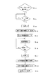
以下、無人搬送車1が、荷物の自動搬送作業を行う場合の作動の一例について、図7のフローチャートにしたがって説明する。なお、無人搬送車1が自動搬送作業を行う作業場の床面には、図6の如く、予め、磁気テープからなる走行用ライン2、移載用ライン3、ステップマーカー4、停止マーカープレート5、停止ライン30,31等が敷設される。
【0018】
無人搬送車1は(図6参照。通常走行は後進方向)、まず、ステップ(以下、単にSで示す)100で、番地センサ89によって、ステップマーカー4に記憶された情報を読み取り、荷積み動作を行うか否かを判断し、荷積み動作を行うと判断した場合には、S101を実行する。なお、ステップマーカー4には、予め、荷積み作業を行うべきであるか、あるいは荷下ろし作業を行うべきであるかに関する情報、無人搬送車1の旋回方向に関する情報等が記録されている。そして、上述の如く走行用ライン2を検知しながら走行し、S101で、走行用検知装置80がテープ端32を検出したと判断した場合には、S102を実行して一時停止する。さらに、一時停止した後には、S103を実行し、S100で読み取ったステップマーカー4の情報にしたがって、走行用駆動装置10を回転させる。なお、走行用駆動装置10を左に90°回転させる場合には、左の車輪83aを正回転させるとともに右の車輪83bを逆回転させ、走行用駆動装置10が90゜回転したことを光電センサ50が検知した時点で、車輪83a,83bの回転を停止させる。また、走行用駆動装置10を右に90°回転させる場合には、左の車輪83aを逆回転させるとともに右の車輪83bを正回転させ、走行用駆動装置10が90゜回転したことを光電センサ50が検知した時点で、車輪83a,83bの回転を停止させる。
【0019】
そして、S103を実行した後には、S104を実行し、ロック用油圧シリンダ53によりインディックスピース54をハンドルスプロケット55のロック溝9bに嵌め込み、走行用駆動装置10をロックする。しかる後、S105で、左右の車輪83a,83bを、ともに逆回転させることにより、図6の如く、前方の(フォーク6の下側の)前輪16,16を結ぶ線上の中点を中心に旋回する。なお、旋回する際に、左右の車輪83a,83bは、円弧状の軌跡を描くことになるため、左右の車輪83a,83bを同じ速度で回転させると、固定されている走行用駆動装置10に無理な力が加わるばかりでなく、旋回中心が、左右の前輪16,16を結ぶ線上の中点からずれてしまう。それゆえ、内側の車輪83bの回転速度を、外側の車輪83aの回転速度の70%程度にすることによって、旋回を安定させる必要がある。
【0020】
さらに、S105を実行した後には、S106を実行し、走行用検知装置80が停止ライン30を検知したか否か判断し、検知したと判断した場合には、S107を実行して停止する。しかる後、S108を実行し、インディックスピース54を後退させることによって走行用駆動装置10のロックを解除する。そして、S109を実行し、左右の車輪83a,83bを、S103で回転させた方向と逆の方向にそれぞれ回転させ、走行用駆動装置10が正面を向いた時点で回転を停止させる(この動作によって、無人搬送車1は、荷物7の正面を向くことになる)。なお、走行用駆動装置10が、正面を向いたか否かは、光電センサ50によって検知される。
【0021】
そして、走行用駆動装置10が正面を向いた時点で、S110を実行し、再び走行用駆動装置10をロックする。しかる後、S111を実行し、荷積み動作を行うか否かを判断する。そして、荷積み動作を行うと判断した場合には、S112を実行することなくS113を実行し、左右の車輪83a,83bを正回転させることによって前進する(なお、S111で荷積み動作を行わないと判断した場合、すなわち、荷下ろし動作を実行すると判断した場合には、S112を実行し、フォーク6を上限まで上昇させた後に、S113を実行することになる)。また、前進の際には、走行用検知装置80によって、移載用ライン3を検知し続けるが、検知された情報とは無関係に、左右の車輪83a,83bを一定の速度で回転させて定速前進する。しかる後、S114を実行し、前進中に、停止マーカー5があるか否かを判断し続け、停止マーカー5があったと判断した場合には、S115を実行して一時停止する。
【0022】
S115を実行した後には、S116で、荷積み動作を行うか否かを判断し、荷積み動作を行うと判断した場合には、S118を実行し、フォーク6を上限まで上昇させて、荷物7をすくい上げ、所定の場所に荷物7を移動させる(なお、S116で荷積み動作を行わない、すなわち、荷下ろし動作を行うと判断した場合には、S117を実行し、フォーク6を下限まで下降させて、荷物1を荷受台等の上あるいは床面に下ろすことになる)。しかる後、S119を実行し、固定されている走行用駆動装置10のロックを解除する。
【0023】
次に、S120を実行し、左右の車輪83a,83bを、ともに逆回転させることによって後進する。なお、後進する際には、S121で、走行用検知装置80によって移載用ライン3を検知し続け、テープ端部33があるか否かを判断し続ける。そして、テープ端部33を検知した時点で、S122を実行して一時停止する。しかる後、S123を実行し、S103からS109と同様の動作を行い、90゜旋回して、移載用ライン3から走行用ライン2へ移動する。そして、走行用ライン2へ移動した後には、S124を実行し、次の荷積み作業エリア(あるいは荷下ろし作業エリア)へと後進走行する。
【0024】
さらに、無人搬送車1が、Uターンを行う場合の作動の一例について、図8のフローチャートにしたがって説明する。無人搬送車1は、S150で、ステップマーカー4に記憶された情報を読み取り、Uターンを行うか否かを判断し、Uターンを行うと判断した場合には、S151を実行し、走行用検知装置80によって走行ライン2を検出しながら走行する。そして、テープ端部32を検出した時点でS152を実行して一時停止し、しかる後、S153を実行し、S150で読み取ったステップマーカー4の情報にしたがって、走行用駆動装置10を回転させる。さらに、続くS154で、インディックスピース54をハンドルスプロケット55のロック溝9bに嵌め込むことによって、走行用駆動装置10をロックした後に、S155を実行し、図9の如く、左右の車輪83a,83bをともに逆回転させることにより、前方の前輪16,16を結ぶ線上の中点を中心に旋回する。さらに、S156で、走行用検知装置80が停止ライン8を検知したか否か判断し、検知したと判断した場合には、S157を実行して停止する。しかる後、S158を実行し、インディックスピース54を後退させることによって走行用駆動装置10のロックを解除する。さらに、S159を実行し、左右の車輪83a,83bを、S153で回転させた方向と逆の方向に、それぞれ回転させ、走行用駆動装置10が正面を向いた時点で回転を停止させる。しかる後、S160を実行して、後進走行を再開する。
【0025】
無人搬送車1は、上記の如く、平行に設けた2つの車輪83a,83bを別個独立に駆動する走行用駆動装置10が、車体21に、水平面内で回転自在に設けられており、その走行用駆動装置10が回転することによって、全体を静止させたままで走行方向を転換することができるため、後進する場合のみならず、前進する場合でも方向制御が容易であり、自動走行モードにおいて、荷積み作業や荷下ろし作業も容易かつ正確に行うことができる。また、狭いスペースでも容易に方向転換することができる。さらに、無人搬送車1は、サーボ制御機構等の複雑な制御機構が採用されていないため、安価、かつ容易に製造することができる。
【0026】
また、無人搬送車1は、上記の如く、走行用駆動装置10が、2つの車輪83a,83bの支軸19を前進方向に対して垂直にした状態(すなわち、まっすぐな状態)、およびその状態を中心として左右に90゜回転した状態でロック自在になっている。このため、走行用駆動装置10をまっすぐな状態でロックすることによって、直進走行を安定したものにすることができるし、走行用駆動装置10を左あるいは右に90゜回転させた状態でロックし、内側の車輪(83aあるいは83b)の回転速度を外側の車輪(83bあるいは83a)の回転速度の70%程度に制御することによって、方向転換時の走行を安定したもの(規則正しい軌跡を描くもの)にすることができる。
【0027】
さらに、無人搬送車1は、走行用駆動装置10を回転自在に支持したドライシャフト52にハンドルスプロケット55が固着されており、そのハンドルスプロケット55に、ドライシャフト52を中心として90゜間隔で3つのロック溝9a,9b,9cが設けられているとともに、ハンドルスプロケット55と隣接した部位に、ロック溝9a,9b,9cと嵌合可能なインデックスピース54が、ロック用油圧シリンダ53によって前進、後退自在に付設されており、前進したインデックスピース54がロック溝9a,9b,9cに嵌合することによって、走行用駆動装置10がロックされるものであるため、走行用駆動装置10を、回転していない状態、左に90゜回転した状態、右に90゜回転した状態で確実にロックすることができる。なお、無人搬送車1は、フォーク6を昇降させるための油圧機構を、走行用駆動装置10をロックするための油圧機構としても利用するものであるため、構造がシンプルでメンテナンスが容易である上、安価に製造することができる。
【0028】
加えて、無人搬送車1は、走行用駆動装置10が、2つの車輪83a,83bの支軸19,20を前進方向に対して垂直にした状態、およびその状態を中心として左右に90゜回転した状態のいずれかであることを検知する検知機構(光電センサ50)が設けられているため、走行用駆動装置10を、回転していない状態、左に90゜回転した状態、右に90゜回転した状態にする場合に、短時間のうちに正しい位置を割り出すことができる。
【0029】
なお、本発明の無人搬送車の構成は、上記した各実施例の態様に何ら限定されるものではなく、フォーク、車体、走行用駆動装置(モータ、駆動輪等)、フォーク用シリンダ、ロック用シリンダ、油圧機構、前輪、補助輪、インデックスピース、ハンドルスプロケット、およびハンドルスプロケットに設ける溝の数、ドライシャフト、走行用検知装置、光電センサ等の構成を、本発明の趣旨を逸脱しない範囲で、必要に応じて適宜変更できる。
【0030】
たとえば、走行用駆動装置のロック機構は、油圧装置によりインデックスピースをハンドルスプロケットの溝に嵌め込むものに限定されず、空圧シリンダを用いたものや、電磁ソレノイドを利用したもの等でも良い。また、2つの駆動輪を駆動するモータが走行用駆動装置の内部に設けられたものに限定されず、モータが走行用駆動装置以外の部分に設けられたものでも良い。さらに、無人搬送車に荷積み作業や荷下ろし作業を実行させる場合の作業場のレイアウト(走行ライン、移載ライン、停止ライン、テープ端部、ステップマーカー、停止マーカーの個数や配置等)も、上記実施形態の態様に何ら限定されず、走行ラインや移載ライン等の磁気テープを壁面に設けること等も可能である。加えて、無人搬送機を走行させたりフォークを昇降させたりするためのプログラムも、上記実施形態の態様に何ら限定されない。また、無人搬送機は、磁気テープの情報を読み取りながら自動作業するものに限定されず、外部から、有線あるいは無線でリモートコントロールされるものでも良い。
【0031】
【発明の効果】
本発明に係る無人搬送車は、上記の如く、平行に設けた2つの駆動輪を別個独立に駆動する走行用駆動装置が、車体に、水平面内で回転自在に設けられており、その走行用駆動装置が回転することによって、全体を静止させたままで走行方向を転換することができるため、後進する場合のみならず、前進する場合でも方向制御が容易であり、自動走行モードによって、荷積み作業や荷下ろし作業も容易かつ正確に行うことができる。また、狭いスペースでも容易に方向転換することができるため、余分なレイアウトスペースや複雑なレイアウトを必要としない。さらに、サーボ制御機構等の複雑な制御機構が採用されていないため、安価、かつ容易に製造することができる。
【0032】
さらに、本発明に係る無人搬送車は、走行用駆動装置が、2つの駆動輪の支軸を前進方向に対して垂直にした状態(まっすぐな状態)、およびその状態を中心として左右に90゜回転した状態でロック自在になっているため、走行用駆動装置をまっすぐな状態でロックすることによって、直進走行を安定したものにすることができるし、走行用駆動装置を左あるいは右に90゜回転させた状態でロックし、内側の車輪の回転速度を外側の車輪の回転速度の70%程度に制御することによって、方向転換時の走行を安定したものにすることができる。
【0033】
加えて、本発明に係る無人搬送車は、走行用駆動装置を回転自在に支持した回転軸にフランジが固着されており、そのフランジに、回転軸を中心として90゜間隔で3つの溝が設けられているとともに、フランジと隣接した部位に、溝と嵌合可能な突起体が、油圧シリンダによって前進、後退自在に付設されており、前進した突起体が溝に嵌合することによって、走行用駆動装置がロックされるものであるため、走行用駆動装置を、回転していない状態、左に90゜回転した状態、右に90゜回転した状態で確実にロックすることができる。したがって、本発明に係る無人搬送車によれば、直進走行および方向転換時の走行安定性がより精度の高いものとなる。
【図面の簡単な説明】
【図1】無人搬送車の側面を示す説明図である。
【図2】走行用駆動装置を下から見た状態を示す説明図である。
【図3】走行用駆動装置の設置部分を示す説明図である。
【図4】ハンドルスプロケット、ロック用油圧シリンダを示す説明図である。
【図5】無人搬送車の油圧機構を示す説明図である。
【図6】無人搬送車が作動する様子を示す説明図である。
【図7】無人搬送車の作動内容を示すフローチャートである。
【図8】無人搬送車の作動内容を示すフローチャートである。
【図9】無人搬送車が作動する様子を示す説明図である。
【符号の説明】
1・・無人搬送車、2・・走行用ライン、3・・移載用ライン、4・・ステップマーカー、5・・停止マーカー、6・・フォーク、7・・荷物、8・・停止ライン、9a〜9c・・ロック用溝、10・・走行用駆動装置、11・・フォーク用油圧シリンダ、14・・油圧ユニット、15・・操作パネル、16・・前輪、17・・シャーシ、18・・バッテリー、19・・支軸、20・・フランジスプロケット、21・・車体、22・・チェーンテンショナー、23・・回転軸、24・・スプロケット、25・・チェーン、26・・ハンドル、27・・補助輪、30,31・・停止ライン、32,33・・テープ端部、50・・光電センサ、51・・角度検出板、52・・ドライシャフト、53・・ロック用油圧シリンダ、54・・インデックスピース、55・・ハンドルスプロケット、62・・油圧ポンプ、63,64,65・・切換弁、66・・流量制御弁、67・・タンク、68・・圧油供給管路、69・・上昇管路、70・・ロック管路、71・・逆止弁、72・・下降管路、80・・走行用検知装置、81,82・・駆動用モータ、83a,83b・・車輪、84a,84b・・スプロケット、85a,85b・・チェーン、86,87・・駆動軸、88a,88b・・スプロケット、89・・番地センサ、90・・バンパーフレーム、91・・バンパーセンサ、S1・・フォーク用油圧シリンダの手動時の操作スイッチ、S2・・ロック用油圧シリンダの手動時の操作スイッチ。[0001]
BACKGROUND OF THE INVENTION
The present invention relates to an automatic guided vehicle that automatically carries a cargo.
[0002]
[Prior art]
As a conventional automatic guided vehicle, a fork is provided at the front of the vehicle body, and two drive wheels that are independently driven are provided at the rear of the vehicle body, so that the difference in rotational speed between the two drive wheels is different. There is known a vehicle that changes the direction of travel by attaching it (a so-called two-wheel speed difference control type automatic guided vehicle).
[0003]
[Problems to be solved by the invention]
However, since the conventional automatic guided vehicle is provided with a long fork at the front, if the rotational speed of the two drive wheels is made different during traveling, the fork shakes, particularly in the case of moving forward. It was difficult to control. Therefore, it has been difficult to perform the loading operation and the unloading operation in which the forward movement is indispensable in the automatic traveling mode. Further, in order to solve such problems, a servo control mechanism or the like must be mounted as a control mechanism, and the manufacturing cost tends to increase. Furthermore, the above conventional automatic guided vehicle draws a large R (curvature radius) when changing direction (when it bends at a right angle or when it makes a U-turn), so it cannot change direction in a narrow space. There was also.
[0004]
The purpose of the present invention is to solve the problems of the conventional automatic guided vehicle, easy to control the direction when moving forward, and can operate in the automatic travel mode even when loading and unloading work. In addition, it is an object of the present invention to provide an automatic guided vehicle that can change direction even in a narrow space and that can be manufactured at low cost.
[0005]
[Means for Solving the Problems]
The present invention is an automatic guided vehicle that automatically travels in the front-rear direction and automatically raises and lowers a fork installed in front, and a traveling drive device that independently drives two drive wheels provided in parallel is provided. Free to rotate in the horizontal plane Provided , A flange is fixed to a rotating shaft that rotatably supports the driving device for driving, and grooves are provided at 90 ° intervals around the rotating shaft, and a groove is formed in a portion adjacent to the flange. Protrusions that can be fitted together are attached to the hydraulic cylinder so that it can be moved forward and backward. , When the projecting body that has advanced is fitted into the groove, the driving device for traveling is in a state in which the support shafts of the two drive wheels are perpendicular to the forward direction, and 90 ° in both the left and right directions centering on the state. Locked in a rotated state It is characterized by this.
[0006]
DETAILED DESCRIPTION OF THE INVENTION
Hereinafter, an embodiment of the automatic guided vehicle according to the present invention will be described in detail with reference to the drawings.
[0007]
FIG. 1 shows a side view of the automatic guided vehicle. In the automatic guided
[0008]
FIG. 2 shows a state in which the
[0009]
FIG. 3 shows an installation portion of the travel drive device 10 (as viewed from the rear of the travel drive device 10), and a dry shaft (rotary shaft) is disposed on the upper portion of the
[0010]
FIG. 4 shows a state in which the handle sprocket 55 and the locking
[0011]
On the other hand, on the side opposite to the locking
[0012]
FIG. 5 shows the hydraulic mechanism of the automatic guided
[0013]
In the automatic guided
[0014]
In addition, the automatic guided
[0015]
On the other hand, with the locking
[0016]
Further, when the manual operation is performed, the operation switch S1 of the fork
[0017]
Hereinafter, an example of the operation in the case where the automatic guided
[0018]
In the automatic guided vehicle 1 (see FIG. 6, normal traveling is in the reverse direction), first, in step (hereinafter, simply indicated by S) 100, the information stored in the step marker 4 is read by the
[0019]
After S103 is executed, S104 is executed, and the
[0020]
Further, after S105 is executed, S106 is executed to determine whether or not the
[0021]
Then, when the
[0022]
After executing S115, it is determined whether or not the loading operation is performed in S116. If it is determined that the loading operation is performed, S118 is executed to raise the
[0023]
Next, S120 is performed and the left and
[0024]
Furthermore, an example of the operation when the automatic guided
[0025]
In the automatic guided
[0026]
Further, as described above, the automatic guided
[0027]
Further, in the automatic guided
[0028]
In addition, in the automatic guided
[0029]
The configuration of the automatic guided vehicle of the present invention is not limited to the above-described embodiments. Forks, vehicle bodies, travel drive devices (motors, drive wheels, etc.), fork cylinders, and locks are used. The configuration of the cylinder, hydraulic mechanism, front wheel, auxiliary wheel, index piece, handle sprocket, number of grooves provided in the handle sprocket, dry shaft, travel detection device, photoelectric sensor, etc., without departing from the spirit of the present invention, It can be changed as needed.
[0030]
For example, the lock mechanism of the driving device for traveling is not limited to the one in which the index piece is fitted into the groove of the handle sprocket by the hydraulic device, but may be one using a pneumatic cylinder or one using an electromagnetic solenoid. Further, the motor for driving the two drive wheels is not limited to the one provided in the driving device for traveling, and the motor may be provided in a portion other than the driving device for traveling. In addition, the layout of the workplace (running line, transfer line, stop line, tape edge, step marker, number and arrangement of stop markers, etc.) when loading and unloading work to the automated guided vehicle is also described above. It is not limited at all to the aspect of the embodiment, and a magnetic tape such as a travel line or a transfer line can be provided on the wall surface. In addition, the program for running the automatic guided machine or raising and lowering the fork is not limited to the aspect of the above embodiment. Further, the automatic guided machine is not limited to one that performs automatic operation while reading information on a magnetic tape, and may be one that is remotely controlled from outside by wired or wireless.
[0031]
【The invention's effect】
The automatic guided vehicle according to the present invention is As described above, the driving device for driving independently driving the two driving wheels provided in parallel is provided on the vehicle body so as to be rotatable in a horizontal plane, and when the driving device for driving rotates, The direction of travel can be changed while the whole is stationary, so it is easy to control the direction not only when moving backwards but also when moving forward, and loading and unloading operations are easy and accurate with the automatic travel mode. Can be done. Further, since the direction can be easily changed even in a narrow space, no extra layout space or complicated layout is required. Furthermore, since a complicated control mechanism such as a servo control mechanism is not employed, it can be manufactured inexpensively and easily.
[0032]
Furthermore, the automatic guided vehicle according to the present invention is The driving device for traveling can be locked in a state where the support shafts of the two driving wheels are perpendicular to the forward direction (straight state) and rotated 90 degrees left and right around the state. Therefore, it is possible to stabilize the straight traveling by locking the traveling drive device in a straight state, and to lock the traveling drive device by rotating it 90 degrees left or right, By controlling the rotational speed of the wheel to about 70% of the rotational speed of the outer wheel, the traveling at the time of turning can be stabilized.
[0033]
In addition, the automatic guided vehicle according to the present invention is The flange is fixed to a rotating shaft that rotatably supports the driving device for traveling, and the groove is provided with three grooves at intervals of 90 ° around the rotating shaft, and at a portion adjacent to the flange. The projecting body that can be fitted to the groove is attached by a hydraulic cylinder so as to be able to move forward and backward, and the traveling drive device is locked by fitting the advanced projecting body into the groove. The driving device for traveling can be securely locked in a non-rotating state, a state rotated 90 ° to the left, and a state rotated 90 ° to the right. Therefore, According to the present invention According to the automatic guided vehicle, the traveling stability during straight traveling and the direction change becomes higher accuracy.
[Brief description of the drawings]
FIG. 1 is an explanatory view showing a side surface of an automatic guided vehicle.
FIG. 2 is an explanatory view showing a state in which a traveling drive device is viewed from below.
FIG. 3 is an explanatory view showing an installation part of a driving device for traveling.
FIG. 4 is an explanatory view showing a handle sprocket and a hydraulic cylinder for locking.
FIG. 5 is an explanatory view showing a hydraulic mechanism of the automatic guided vehicle.
FIG. 6 is an explanatory diagram showing a state in which the automatic guided vehicle operates.
FIG. 7 is a flowchart showing the operation content of the automatic guided vehicle.
FIG. 8 is a flowchart showing the operation content of the automatic guided vehicle.
FIG. 9 is an explanatory diagram showing a state in which the automatic guided vehicle operates.
[Explanation of symbols]
1 .... Automatic guided
Claims (1)
平行に設けた2つの駆動輪を別個独立に駆動する走行用駆動装置が、車体に、水平面内で回転自在に設けられており、
その走行用駆動装置を回転自在に支持した回転軸にフランジが固着されており、そのフランジに、回転軸を中心として90゜間隔で溝が設けられているとともに、フランジと隣接した部位に、溝と嵌合可能な突起体が、油圧シリンダによって前進、後退自在に付設されており、
前進した突起体が溝に嵌合することによって、走行用駆動装置が、2つの駆動輪の支軸を前進方向に対して垂直にした状態、およびその状態を中心として左右どちらの方向でも90゜回転した状態でロックされることを特徴とする無人搬送車。An automatic guided vehicle that automatically travels in the front-rear direction and automatically raises and lowers the fork installed in the front,
A driving device for driving that independently drives two driving wheels provided in parallel is provided on the vehicle body so as to be rotatable in a horizontal plane,
A flange is fixed to a rotating shaft that rotatably supports the driving device for driving, and grooves are provided at 90 ° intervals around the rotating shaft, and a groove is formed in a portion adjacent to the flange. Protrusions that can be fitted with are attached to the hydraulic cylinder so that it can be moved forward and backward .
When the projecting body that has advanced is fitted into the groove, the driving device for traveling is in a state in which the support shafts of the two drive wheels are perpendicular to the forward direction, and 90 ° in both the left and right directions centering on the state. An automatic guided vehicle that is locked in a rotated state .
Priority Applications (1)
| Application Number | Priority Date | Filing Date | Title |
|---|---|---|---|
| JP19501499A JP4354577B2 (en) | 1999-07-08 | 1999-07-08 | Automated guided vehicle |
Applications Claiming Priority (1)
| Application Number | Priority Date | Filing Date | Title |
|---|---|---|---|
| JP19501499A JP4354577B2 (en) | 1999-07-08 | 1999-07-08 | Automated guided vehicle |
Publications (2)
| Publication Number | Publication Date |
|---|---|
| JP2001019382A JP2001019382A (en) | 2001-01-23 |
| JP4354577B2 true JP4354577B2 (en) | 2009-10-28 |
Family
ID=16334106
Family Applications (1)
| Application Number | Title | Priority Date | Filing Date |
|---|---|---|---|
| JP19501499A Expired - Fee Related JP4354577B2 (en) | 1999-07-08 | 1999-07-08 | Automated guided vehicle |
Country Status (1)
| Country | Link |
|---|---|
| JP (1) | JP4354577B2 (en) |
Cited By (1)
| Publication number | Priority date | Publication date | Assignee | Title |
|---|---|---|---|---|
| CN101657274B (en) * | 2007-03-23 | 2012-05-30 | 奥尔德斯·蒙塔古·希克斯 | An apparatus to process used materials |
Families Citing this family (2)
| Publication number | Priority date | Publication date | Assignee | Title |
|---|---|---|---|---|
| CN105060177A (en) * | 2015-08-12 | 2015-11-18 | 山东建筑大学 | Small stacking machine |
| CN108974951B (en) * | 2018-07-16 | 2023-08-18 | 玖龙纸业(重庆)有限公司 | Stacking machine |
-
1999
- 1999-07-08 JP JP19501499A patent/JP4354577B2/en not_active Expired - Fee Related
Cited By (1)
| Publication number | Priority date | Publication date | Assignee | Title |
|---|---|---|---|---|
| CN101657274B (en) * | 2007-03-23 | 2012-05-30 | 奥尔德斯·蒙塔古·希克斯 | An apparatus to process used materials |
Also Published As
| Publication number | Publication date |
|---|---|
| JP2001019382A (en) | 2001-01-23 |
Similar Documents
| Publication | Publication Date | Title |
|---|---|---|
| JP7092420B2 (en) | Intelligent parking lot and its work-intensive transfer robot | |
| CN104854018A (en) | A motorised truck with tiller | |
| EP2573040A1 (en) | Automatically guided vehicle for towing a load | |
| JP4354577B2 (en) | Automated guided vehicle | |
| US20140100723A1 (en) | Automated guided vehicle sidestep motion apparatus and method | |
| EP0456769B1 (en) | Apparatus and method for controllably positioning forks of a material handling vehicle | |
| JP2007048157A (en) | Travel control system for automated guided carriage cart | |
| JPH11171010A (en) | Unmanned carrier | |
| CN206298317U (en) | A kind of fork truck type AGV system of positioning function of being moveed backward with high accuracy | |
| KR100598703B1 (en) | An automatic guided vehicle | |
| CN115056697B (en) | Automatic butt-joint intelligent traction system and traction method | |
| JP2007320545A (en) | Travelling car and travelling car system | |
| JPS6231524A (en) | Robot transport vehicle | |
| JPH09267746A (en) | Device for connecting and guiding carrier and truck | |
| JP2916194B2 (en) | Steering mechanism for aerial work vehicles | |
| JP3896801B2 (en) | Goods transport vehicle | |
| JP4304588B2 (en) | Goods transport vehicle | |
| JP5134403B2 (en) | Automated guided vehicle, control method thereof, and driving line of automated guided vehicle | |
| KR200368595Y1 (en) | Steering Preventive Apparatus for Self Steer Axle | |
| JPH0995235A (en) | Carriage running system | |
| CN106347459A (en) | Method and device for automatically aligning steering wheel | |
| CA2184508A1 (en) | Magnetically guided vehicle | |
| JPH09311723A (en) | Device for detecting steering angle of carrier | |
| KR200372545Y1 (en) | Steering Preventive Apparatus for Self Steer Axle | |
| JPH038970Y2 (en) |
Legal Events
| Date | Code | Title | Description |
|---|---|---|---|
| A711 | Notification of change in applicant |
Free format text: JAPANESE INTERMEDIATE CODE: A712 Effective date: 20040617 |
|
| A621 | Written request for application examination |
Free format text: JAPANESE INTERMEDIATE CODE: A621 Effective date: 20060407 |
|
| A977 | Report on retrieval |
Free format text: JAPANESE INTERMEDIATE CODE: A971007 Effective date: 20081106 |
|
| A131 | Notification of reasons for refusal |
Free format text: JAPANESE INTERMEDIATE CODE: A131 Effective date: 20090310 |
|
| A521 | Written amendment |
Free format text: JAPANESE INTERMEDIATE CODE: A523 Effective date: 20090428 |
|
| TRDD | Decision of grant or rejection written | ||
| A01 | Written decision to grant a patent or to grant a registration (utility model) |
Free format text: JAPANESE INTERMEDIATE CODE: A01 Effective date: 20090630 |
|
| A01 | Written decision to grant a patent or to grant a registration (utility model) |
Free format text: JAPANESE INTERMEDIATE CODE: A01 |
|
| A61 | First payment of annual fees (during grant procedure) |
Free format text: JAPANESE INTERMEDIATE CODE: A61 Effective date: 20090730 |
|
| R150 | Certificate of patent or registration of utility model |
Free format text: JAPANESE INTERMEDIATE CODE: R150 |
|
| FPAY | Renewal fee payment (event date is renewal date of database) |
Free format text: PAYMENT UNTIL: 20120807 Year of fee payment: 3 |
|
| FPAY | Renewal fee payment (event date is renewal date of database) |
Free format text: PAYMENT UNTIL: 20120807 Year of fee payment: 3 |
|
| FPAY | Renewal fee payment (event date is renewal date of database) |
Free format text: PAYMENT UNTIL: 20150807 Year of fee payment: 6 |
|
| R250 | Receipt of annual fees |
Free format text: JAPANESE INTERMEDIATE CODE: R250 |
|
| LAPS | Cancellation because of no payment of annual fees |