CN101657274B - An apparatus to process used materials - Google Patents
An apparatus to process used materials Download PDFInfo
- Publication number
- CN101657274B CN101657274B CN2008800123714A CN200880012371A CN101657274B CN 101657274 B CN101657274 B CN 101657274B CN 2008800123714 A CN2008800123714 A CN 2008800123714A CN 200880012371 A CN200880012371 A CN 200880012371A CN 101657274 B CN101657274 B CN 101657274B
- Authority
- CN
- China
- Prior art keywords
- waste materials
- chamber
- washing
- drying
- operated
- Prior art date
- Legal status (The legal status is an assumption and is not a legal conclusion. Google has not performed a legal analysis and makes no representation as to the accuracy of the status listed.)
- Active
Links
- 239000000463 material Substances 0.000 title claims abstract description 54
- 238000000034 method Methods 0.000 title claims abstract description 31
- 230000008569 process Effects 0.000 title claims abstract description 25
- 238000001035 drying Methods 0.000 claims abstract description 46
- 238000005406 washing Methods 0.000 claims abstract description 40
- 238000003860 storage Methods 0.000 claims abstract description 24
- 239000000203 mixture Substances 0.000 claims abstract description 6
- 239000002699 waste material Substances 0.000 claims description 96
- 230000006698 induction Effects 0.000 claims description 23
- 230000007246 mechanism Effects 0.000 claims description 5
- 239000002245 particle Substances 0.000 claims description 5
- 238000005507 spraying Methods 0.000 claims description 5
- 230000006835 compression Effects 0.000 claims description 3
- 238000007906 compression Methods 0.000 claims description 3
- 238000010438 heat treatment Methods 0.000 claims description 3
- 239000007788 liquid Substances 0.000 claims description 3
- 230000005540 biological transmission Effects 0.000 claims description 2
- 238000007599 discharging Methods 0.000 claims description 2
- 238000009434 installation Methods 0.000 claims description 2
- 238000011112 process operation Methods 0.000 claims description 2
- 238000004519 manufacturing process Methods 0.000 abstract description 6
- 229920003023 plastic Polymers 0.000 description 28
- 239000004033 plastic Substances 0.000 description 28
- 239000011521 glass Substances 0.000 description 23
- 229920001903 high density polyethylene Polymers 0.000 description 17
- 239000004700 high-density polyethylene Substances 0.000 description 17
- 229920000728 polyester Polymers 0.000 description 11
- 229910000831 Steel Inorganic materials 0.000 description 9
- 239000010959 steel Substances 0.000 description 9
- 238000004140 cleaning Methods 0.000 description 8
- 229910052751 metal Inorganic materials 0.000 description 8
- 239000002184 metal Substances 0.000 description 8
- 229910052782 aluminium Inorganic materials 0.000 description 7
- XAGFODPZIPBFFR-UHFFFAOYSA-N aluminium Chemical compound [Al] XAGFODPZIPBFFR-UHFFFAOYSA-N 0.000 description 7
- 239000006063 cullet Substances 0.000 description 5
- 238000001514 detection method Methods 0.000 description 4
- 229920001684 low density polyethylene Polymers 0.000 description 3
- 239000004702 low-density polyethylene Substances 0.000 description 3
- 239000000123 paper Substances 0.000 description 3
- 238000000926 separation method Methods 0.000 description 3
- 239000007921 spray Substances 0.000 description 3
- XLYOFNOQVPJJNP-UHFFFAOYSA-N water Substances O XLYOFNOQVPJJNP-UHFFFAOYSA-N 0.000 description 3
- 239000004743 Polypropylene Substances 0.000 description 2
- 239000003086 colorant Substances 0.000 description 2
- 235000013305 food Nutrition 0.000 description 2
- 230000005484 gravity Effects 0.000 description 2
- 238000002536 laser-induced breakdown spectroscopy Methods 0.000 description 2
- 238000003801 milling Methods 0.000 description 2
- 238000012856 packing Methods 0.000 description 2
- 229920001155 polypropylene Polymers 0.000 description 2
- 229920000915 polyvinyl chloride Polymers 0.000 description 2
- 239000004800 polyvinyl chloride Substances 0.000 description 2
- 238000010298 pulverizing process Methods 0.000 description 2
- 238000011084 recovery Methods 0.000 description 2
- 239000000126 substance Substances 0.000 description 2
- LFQSCWFLJHTTHZ-UHFFFAOYSA-N Ethanol Chemical compound CCO LFQSCWFLJHTTHZ-UHFFFAOYSA-N 0.000 description 1
- 238000001157 Fourier transform infrared spectrum Methods 0.000 description 1
- 239000004793 Polystyrene Substances 0.000 description 1
- 241000779819 Syncarpia glomulifera Species 0.000 description 1
- 238000005299 abrasion Methods 0.000 description 1
- 230000009471 action Effects 0.000 description 1
- 230000003213 activating effect Effects 0.000 description 1
- 238000004458 analytical method Methods 0.000 description 1
- 230000000712 assembly Effects 0.000 description 1
- 238000000429 assembly Methods 0.000 description 1
- 235000013361 beverage Nutrition 0.000 description 1
- 239000011111 cardboard Substances 0.000 description 1
- 230000008859 change Effects 0.000 description 1
- 239000010632 citronella oil Substances 0.000 description 1
- 210000000078 claw Anatomy 0.000 description 1
- 238000005520 cutting process Methods 0.000 description 1
- 230000007423 decrease Effects 0.000 description 1
- 239000011928 denatured alcohol Substances 0.000 description 1
- 238000005538 encapsulation Methods 0.000 description 1
- 238000005516 engineering process Methods 0.000 description 1
- 230000003203 everyday effect Effects 0.000 description 1
- 239000005357 flat glass Substances 0.000 description 1
- 239000012634 fragment Substances 0.000 description 1
- 239000003292 glue Substances 0.000 description 1
- 239000002440 industrial waste Substances 0.000 description 1
- 229910052500 inorganic mineral Inorganic materials 0.000 description 1
- 239000003350 kerosene Substances 0.000 description 1
- 239000011707 mineral Substances 0.000 description 1
- 238000009928 pasteurization Methods 0.000 description 1
- 239000001739 pinus spp. Substances 0.000 description 1
- -1 polypropylene Polymers 0.000 description 1
- 239000013014 purified material Substances 0.000 description 1
- 239000002994 raw material Substances 0.000 description 1
- 238000010223 real-time analysis Methods 0.000 description 1
- 239000010819 recyclable waste Substances 0.000 description 1
- 238000004064 recycling Methods 0.000 description 1
- 238000007790 scraping Methods 0.000 description 1
- 238000007789 sealing Methods 0.000 description 1
- 239000007787 solid Substances 0.000 description 1
- 239000011343 solid material Substances 0.000 description 1
- 239000005315 stained glass Substances 0.000 description 1
- 230000001954 sterilising effect Effects 0.000 description 1
- 238000004659 sterilization and disinfection Methods 0.000 description 1
- 230000032258 transport Effects 0.000 description 1
- 229940036248 turpentine Drugs 0.000 description 1
- 230000000007 visual effect Effects 0.000 description 1
Images


Classifications
-
- B—PERFORMING OPERATIONS; TRANSPORTING
- B65—CONVEYING; PACKING; STORING; HANDLING THIN OR FILAMENTARY MATERIAL
- B65F—GATHERING OR REMOVAL OF DOMESTIC OR LIKE REFUSE
- B65F1/00—Refuse receptacles; Accessories therefor
- B65F1/0033—Refuse receptacles; Accessories therefor specially adapted for segregated refuse collecting, e.g. receptacles with several compartments; Combination of receptacles
-
- B—PERFORMING OPERATIONS; TRANSPORTING
- B08—CLEANING
- B08B—CLEANING IN GENERAL; PREVENTION OF FOULING IN GENERAL
- B08B3/00—Cleaning by methods involving the use or presence of liquid or steam
- B08B3/02—Cleaning by the force of jets or sprays
-
- B—PERFORMING OPERATIONS; TRANSPORTING
- B08—CLEANING
- B08B—CLEANING IN GENERAL; PREVENTION OF FOULING IN GENERAL
- B08B9/00—Cleaning hollow articles by methods or apparatus specially adapted thereto
- B08B9/08—Cleaning containers, e.g. tanks
- B08B9/20—Cleaning containers, e.g. tanks by using apparatus into or on to which containers, e.g. bottles, jars, cans are brought
- B08B9/28—Cleaning containers, e.g. tanks by using apparatus into or on to which containers, e.g. bottles, jars, cans are brought the apparatus cleaning by splash, spray, or jet application, with or without soaking
- B08B9/30—Cleaning containers, e.g. tanks by using apparatus into or on to which containers, e.g. bottles, jars, cans are brought the apparatus cleaning by splash, spray, or jet application, with or without soaking and having conveyors
-
- B—PERFORMING OPERATIONS; TRANSPORTING
- B65—CONVEYING; PACKING; STORING; HANDLING THIN OR FILAMENTARY MATERIAL
- B65F—GATHERING OR REMOVAL OF DOMESTIC OR LIKE REFUSE
- B65F1/00—Refuse receptacles; Accessories therefor
- B65F1/14—Other constructional features; Accessories
- B65F1/16—Lids or covers
-
- B—PERFORMING OPERATIONS; TRANSPORTING
- B65—CONVEYING; PACKING; STORING; HANDLING THIN OR FILAMENTARY MATERIAL
- B65F—GATHERING OR REMOVAL OF DOMESTIC OR LIKE REFUSE
- B65F5/00—Gathering or removal of refuse otherwise than by receptacles or vehicles
-
- F—MECHANICAL ENGINEERING; LIGHTING; HEATING; WEAPONS; BLASTING
- F26—DRYING
- F26B—DRYING SOLID MATERIALS OR OBJECTS BY REMOVING LIQUID THEREFROM
- F26B3/00—Drying solid materials or objects by processes involving the application of heat
- F26B3/02—Drying solid materials or objects by processes involving the application of heat by convection, i.e. heat being conveyed from a heat source to the materials or objects to be dried by a gas or vapour, e.g. air
-
- B—PERFORMING OPERATIONS; TRANSPORTING
- B65—CONVEYING; PACKING; STORING; HANDLING THIN OR FILAMENTARY MATERIAL
- B65F—GATHERING OR REMOVAL OF DOMESTIC OR LIKE REFUSE
- B65F2210/00—Equipment of refuse receptacles
- B65F2210/12—Crushing means
-
- B—PERFORMING OPERATIONS; TRANSPORTING
- B65—CONVEYING; PACKING; STORING; HANDLING THIN OR FILAMENTARY MATERIAL
- B65F—GATHERING OR REMOVAL OF DOMESTIC OR LIKE REFUSE
- B65F2210/00—Equipment of refuse receptacles
- B65F2210/165—Remote controls
-
- B—PERFORMING OPERATIONS; TRANSPORTING
- B65—CONVEYING; PACKING; STORING; HANDLING THIN OR FILAMENTARY MATERIAL
- B65F—GATHERING OR REMOVAL OF DOMESTIC OR LIKE REFUSE
- B65F2210/00—Equipment of refuse receptacles
- B65F2210/168—Sensing means
-
- B—PERFORMING OPERATIONS; TRANSPORTING
- B65—CONVEYING; PACKING; STORING; HANDLING THIN OR FILAMENTARY MATERIAL
- B65F—GATHERING OR REMOVAL OF DOMESTIC OR LIKE REFUSE
- B65F2240/00—Types of refuse collected
- B65F2240/112—Bottles
- B65F2240/1123—Glass
-
- B—PERFORMING OPERATIONS; TRANSPORTING
- B65—CONVEYING; PACKING; STORING; HANDLING THIN OR FILAMENTARY MATERIAL
- B65F—GATHERING OR REMOVAL OF DOMESTIC OR LIKE REFUSE
- B65F2240/00—Types of refuse collected
- B65F2240/112—Bottles
- B65F2240/1126—Plastics
-
- B—PERFORMING OPERATIONS; TRANSPORTING
- B65—CONVEYING; PACKING; STORING; HANDLING THIN OR FILAMENTARY MATERIAL
- B65F—GATHERING OR REMOVAL OF DOMESTIC OR LIKE REFUSE
- B65F2240/00—Types of refuse collected
- B65F2240/12—Cans
-
- Y—GENERAL TAGGING OF NEW TECHNOLOGICAL DEVELOPMENTS; GENERAL TAGGING OF CROSS-SECTIONAL TECHNOLOGIES SPANNING OVER SEVERAL SECTIONS OF THE IPC; TECHNICAL SUBJECTS COVERED BY FORMER USPC CROSS-REFERENCE ART COLLECTIONS [XRACs] AND DIGESTS
- Y02—TECHNOLOGIES OR APPLICATIONS FOR MITIGATION OR ADAPTATION AGAINST CLIMATE CHANGE
- Y02W—CLIMATE CHANGE MITIGATION TECHNOLOGIES RELATED TO WASTEWATER TREATMENT OR WASTE MANAGEMENT
- Y02W30/00—Technologies for solid waste management
- Y02W30/10—Waste collection, transportation, transfer or storage, e.g. segregated refuse collecting, electric or hybrid propulsion
-
- Y—GENERAL TAGGING OF NEW TECHNOLOGICAL DEVELOPMENTS; GENERAL TAGGING OF CROSS-SECTIONAL TECHNOLOGIES SPANNING OVER SEVERAL SECTIONS OF THE IPC; TECHNICAL SUBJECTS COVERED BY FORMER USPC CROSS-REFERENCE ART COLLECTIONS [XRACs] AND DIGESTS
- Y02—TECHNOLOGIES OR APPLICATIONS FOR MITIGATION OR ADAPTATION AGAINST CLIMATE CHANGE
- Y02W—CLIMATE CHANGE MITIGATION TECHNOLOGIES RELATED TO WASTEWATER TREATMENT OR WASTE MANAGEMENT
- Y02W30/00—Technologies for solid waste management
- Y02W30/20—Waste processing or separation
-
- Y—GENERAL TAGGING OF NEW TECHNOLOGICAL DEVELOPMENTS; GENERAL TAGGING OF CROSS-SECTIONAL TECHNOLOGIES SPANNING OVER SEVERAL SECTIONS OF THE IPC; TECHNICAL SUBJECTS COVERED BY FORMER USPC CROSS-REFERENCE ART COLLECTIONS [XRACs] AND DIGESTS
- Y02—TECHNOLOGIES OR APPLICATIONS FOR MITIGATION OR ADAPTATION AGAINST CLIMATE CHANGE
- Y02W—CLIMATE CHANGE MITIGATION TECHNOLOGIES RELATED TO WASTEWATER TREATMENT OR WASTE MANAGEMENT
- Y02W30/00—Technologies for solid waste management
- Y02W30/50—Reuse, recycling or recovery technologies
- Y02W30/52—Mechanical processing of waste for the recovery of materials, e.g. crushing, shredding, separation or disassembly
-
- Y—GENERAL TAGGING OF NEW TECHNOLOGICAL DEVELOPMENTS; GENERAL TAGGING OF CROSS-SECTIONAL TECHNOLOGIES SPANNING OVER SEVERAL SECTIONS OF THE IPC; TECHNICAL SUBJECTS COVERED BY FORMER USPC CROSS-REFERENCE ART COLLECTIONS [XRACs] AND DIGESTS
- Y02—TECHNOLOGIES OR APPLICATIONS FOR MITIGATION OR ADAPTATION AGAINST CLIMATE CHANGE
- Y02W—CLIMATE CHANGE MITIGATION TECHNOLOGIES RELATED TO WASTEWATER TREATMENT OR WASTE MANAGEMENT
- Y02W30/00—Technologies for solid waste management
- Y02W30/50—Reuse, recycling or recovery technologies
- Y02W30/60—Glass recycling
-
- Y—GENERAL TAGGING OF NEW TECHNOLOGICAL DEVELOPMENTS; GENERAL TAGGING OF CROSS-SECTIONAL TECHNOLOGIES SPANNING OVER SEVERAL SECTIONS OF THE IPC; TECHNICAL SUBJECTS COVERED BY FORMER USPC CROSS-REFERENCE ART COLLECTIONS [XRACs] AND DIGESTS
- Y02—TECHNOLOGIES OR APPLICATIONS FOR MITIGATION OR ADAPTATION AGAINST CLIMATE CHANGE
- Y02W—CLIMATE CHANGE MITIGATION TECHNOLOGIES RELATED TO WASTEWATER TREATMENT OR WASTE MANAGEMENT
- Y02W30/00—Technologies for solid waste management
- Y02W30/50—Reuse, recycling or recovery technologies
- Y02W30/62—Plastics recycling; Rubber recycling
Landscapes
- Engineering & Computer Science (AREA)
- Mechanical Engineering (AREA)
- Life Sciences & Earth Sciences (AREA)
- Microbiology (AREA)
- General Engineering & Computer Science (AREA)
- Processing Of Solid Wastes (AREA)
- Separation, Recovery Or Treatment Of Waste Materials Containing Plastics (AREA)
Abstract
An apparatus (1) to process used materials for input into a manufacturing process. The apparatus includes a housing (10) having a top surface (15) and providing a plurality of chambers arranged in descending order. A series of locations (20) are positioned under said top surface and through which used materials are to pass. Each said location being provided for receipt of a predetermined used material. A descending path (25) extends from each said location and provides for the transfer of used material from the respective location successively through the chambers. The chambers include a sensing chamber (30) downstream of said locations and having sensing means (35) operable to sense the composition of used material located within said sensing chamber. The sensing means being operable to activate an alarm if the used material has been placed by a user in an opening for receipt of a different material. A washing/drying chamber (40) downstream of said locations and having means (45) operable to wash and dry used material located within said washing/drying chamber. A processing chamber (50) downstream of said washing/drying chamber and having a processing device (55) operable to reduce the size of used material located within said processing chamber and a storage chamber (60) downstream of said processing chamber and having a series of storage units (65) for receipt of different used material once processed by the apparatus (1).
Description
Technical field
The present invention relates to recycle, relate in particular to waste materials (used materials) is processed into the salvage material that is used for being input to the separation of making processing.
Background technology
Current, exist the recovery of family expenses, commercialization and industrial waste material in the world wide widely.Change in modern times in the city, local authority and/or private contractor collect container, paper and the green waste of recyclable utilization termly from the resident there.Again these refuses are transported to subsequently it is separated into the different materials type and packs terminal bundled or the vanning storage.For example; With clear glass, green glass, amber glass vanning storage; Polyester (PET) plastic bottle and container packing is bundled, with aluminum can vanning storage, that high density polyethylene (HDPE) (HDPE) plastic bottle and container packing is bundled; With cylinder of steel vanning storage, and with paper and green waste vanning storage.
From terminal be collected in the waste materials that will be used make handling and or send to material recovery center (MRF) or send to manufacturing works, this is called as the recycling of waste materials (such as glass and plastic bottle, metal can and other canisters).For example, before being transported to vial manufacturer, earlier glass container is pulverized into cullet usually.At MRF or plastic containers or plastic bottle manufactory plastic containers are pulverized flakiness.Aluminum and steel can are compressed at the MRF place and are transported to the smeltery subsequently so that it is processed into ingot bar.Subsequently, ingot bar is sent to canned manufactory.Current; Huge and the dirty waste materials of collected volume and be transported to MRF and spent great amount of time and cost from resident there; Need unloading, separation, storage, classification, pasteurization material at the MRF place; And produced and to be abandoned in a large number with by the waste materials of junk landfill, thereby can handle recyclable material and its encapsulation is transported to manufacturing works.
At admixture and before, need a kind of device that is used to handle recyclable waste materials in the place of materials used subsequently by local authority or the collection of private contractor.Because said apparatus can separate, clean, pulverize, cut into slices, compress waste materials and processing such as crushing, therefore such device will greatly reduce the cost that reclaims waste materials, and the value of the waste materials of raising recovery.The waste materials that obtains thus all be in separately separation, greatly reduce near the form and the volume of pure material; Handled directly to be input to make thereby can directly be transported to each manufacturing works respectively, and need not extra processing or be transported to MRF.
Summary of the invention
The objective of the invention is to, overcome in fact or part is improved one or more unfavorable aspect of the prior art, or suitable optional mode is provided at least.
At first, disclosed herein is and a kind ofly be used for handling waste materials and make the device of handling to be input to, said device comprises:
Housing has end face and a plurality of chambeies that are provided with the order that descends is provided;
A series of positions, the below and the waste materials that are positioned at said end face will be through said a series of positions, and each said position is used to receive predetermined waste materials;
Descent path extends from each said position and provides from the transmission of each sequence of positions through the waste materials in said chamber;
Said chamber comprises:
Induction cavity is arranged in the downstream of said position and has the sensing device of the composition that can operate the waste materials that is used to respond to said induction cavity; If the user is placed into the opening part that is used to receive different materials with waste materials, then said sensing device can be operated and be used to activate alarm;
The washing/drying chamber is arranged in the downstream of said position and has to operate and is used to clean and the device of dry waste materials in said washing/drying chamber;
Process chamber, the treatment facility that is arranged in the downstream in said washing/drying chamber and has the size that can operate the waste materials that is used to reduce said process chamber; And
The storage chamber is positioned at the downstream of said process chamber and has a series of memory cell that are used to receive the different waste materials after the said apparatus processes.
Preferably, said induction cavity and said washing/drying chamber are in the same chamber.
Preferably, said induction cavity is in the different chambeies with said washing/drying chamber.
Preferably, said device comprises the chucking device, and said chucking device can be operated the said descent path of waste materials or edge that is used for the said induction cavity of clamping and discharge said waste materials.
Preferably, said chucking device comprises a pair of arm relative on the sides adjacent that is positioned at induction cavity, and the arm that is in extended position can be operated the waste materials that is used for the said chamber of clamping, and the arm that is in retrieving position can be operated and is used for discharging waste materials along said descent path.
Preferably, said device comprises and can operate the hydraulic jack that is used between said extended position and retrieving position moving said arm.
Preferably, said device comprises lid, said lid be installed on the said housing and open and close between the position removable to expose or to cover said position.
Preferably, said device comprises the equipment that can operate the lid that is used to remove container.
Preferably, said device comprises the equipment that can operate the tamper-evident parts that are used to remove container.
Preferably, said washing/drying device comprises a plurality of nozzles, and said a plurality of nozzles can be operated and be used for spraying liquid to clean the waste materials in said washing/drying chamber.
Preferably, said washing/drying device comprises a plurality of nozzles, and said a plurality of nozzles can be operated and be used for spraying the waste materials of air with the said washing/drying of drying chamber.
Preferably, said washing/drying device comprises heating element heater.
Preferably, said treatment facility comprises that at least one is shredded, tears, shears, wears into particle to shreds, pulverizes, cuts into slices, crushes or compression device.
Preferably, said device comprises the device that is used for from the one or more chambeies of said path offset.
Preferably, said skew device can be operated and be used for from the said washing/drying of said path offset chamber.
Preferably, said skew device comprises slide mechanism.
Preferably, said skew device comprises boot disk.
Preferably, said device be receive computer-controlled.
Preferably, said device comprises a series of slideways, and said a series of slideways can be operated and be used for waste materials is directed to the predetermined process equipment that is suitable for handling said material.
Preferably, said process chamber comprises a series of slideways, and said a series of slideways can be operated the material that is used for after the treatment facility processing and be directed to the predetermined storage unit that is suitable for receiving said predetermined material.
A kind of method of handling waste materials through operative installations also is provided here; Said device comprises housing, a plurality of chambeies that said housing has end face and is provided with the order that descends; Said method comprises:
Waste materials is placed into the position of the end face below of said housing, and said position is used to receive predetermined waste materials;
Said waste materials is transported to induction cavity;
Respond to the composition of the said waste materials in the said induction cavity, to confirm whether the user is placed into the position that is suitable for receiving same material with said waste materials;
In case correctly sense said waste materials, just said waste materials be transported to the washing/drying chamber;
In said washing/drying chamber, clean and/or dry said waste materials;
Said waste materials is transported to process chamber;
The predetermined process operation of equipment of the waste materials through being suitable for receiving same material is handled said container;
Waste materials after the said processing is transported to the storage chamber; Said storage chamber comprises a series of memory cell of the material after the processing that is used to receive different predetermined materials.
Description of drawings
With reference now to appended accompanying drawing,, only the preferred embodiments of the present invention are described through example, wherein:
Fig. 1 is the side view that is used to handle the device of waste materials;
Fig. 2 is the sectional view along the device shown in Figure 1 of line C-C intercepting;
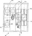
Fig. 3 is the sectional view along the device shown in Figure 1 of line B-B intercepting;
Fig. 4 A and Fig. 4 B are the sectional views along the device shown in Figure 3 of line E and line F intercepting;
Fig. 5 is the sectional view along the device shown in Figure 3 of line G-G intercepting;
Fig. 6 A and Fig. 6 B are sectional view and the side views along the device shown in Figure 1 of line D-D intercepting.
The specific embodiment
In the accompanying drawings, schematically described to be used for handling to make the device of handling 1 to be input to such as container 5 waste materials such as grade.Device 1 comprises housing 10, and this housing 10 has end face 15, is provided with a plurality of chambeies with the order that descends.Below end face 15, orient a series of positions 20, can pass through these positions such as container 5 waste materials such as grade.In the position 20 each all is arranged for receiving predetermined material.Decline passway path 25 20 is extended and is used for from each position that 20 orders transmit waste materials 5 through the chamber from each position.Induction cavity 30 is arranged in the downstream position of position 20 and has the sensing device 35 of the composition that can operate the waste materials that is used for sensitive chamber 30.If the user is placed into 20 places, position that are used to receive different materials with waste materials 5, then sensing device 35 can be operated to be used for activating and report to the police or the visual detector (not shown).Washing/drying chamber 40 also can be positioned at the downstream position of position 20 and have to operate and be used to clean and/or the dry device 45 that is positioned at the waste materials 5 in the middle of the washing/drying chamber 40.Under a kind of form, washing/drying chamber 40 is positioned in the middle of the same chamber with induction cavity 30.Under another form, washing/drying chamber 40 is with in the middle of induction cavity 30 is positioned at different chambeies.Process chamber 50 is positioned at the downstream position in washing/drying chamber 40 and has the treatment facility 55 that can operate the size that is used to reduce to be positioned at the waste materials 5 in the middle of the process chamber 50.Storage chamber 60 is positioned at the downstream position of process chamber 50 and has a series of memory cell 65 that are used to receive by that handled, the different purer material of device 1.Storage chamber 60 can comprise wheel 67 etc.
Best, as can be seen from Figure 1, device 1 comprises is installed on the housing 10 and the lid 70 that can between the opening and closing position, move.Lid 70 during 20 closed positions, lid 70 permission in-positions during open position has then covered position 20.
Best, as can be seen from Figure 2, device 1 comprises operating and is used at induction cavity 30 clamping waste materials 5 or along the chucking device 75 that discharges waste materials 5 on the path 25.Chucking device 75 comprises the relative a pair of arm 80 on the adjacent side that is arranged on induction cavity 30.The arm 80 that is in extended position can be operated the waste materials 5 that is used for clamping chamber 30, and the arm 80 that is in retrieving position can be operated the waste materials 5 that is used on the release way 25.Hydraulic jack, driver etc. 85 be transfer arm 80 between extended position and retrieving position.Arm 80 can be to be suitable for the difformity of specific waste materials and can to adopt modes such as spring-loaded.Device 1 also can comprise the equipment 90 that can operate the lid that is used to remove container 5 or lid retaining device (retainer) and can operate and is used to remove the lid of container 5 or the equipment 95 of top retaining device or tamper-evident parts.
Best, can find out that from Fig. 3, Fig. 4 A, Fig. 4 B, Fig. 5 process chamber 50 comprises treatment facility 52, this treatment facility 52 has chopping at least, tear, shear, wear into particle to shreds, pulverize, cut into slices, crush or compressing mechanism in one.The treatment facility 52 that device 1 is adopted depends on the certain material that will be processed.
Best, can find out from Fig. 4 A and Fig. 4 B that device 1 comprises can operate a series of slideways (chute) 100 that are used for waste materials 5 is directed to the predetermined process equipment 52 that can be suitable for handling material.A series of slideways 105 in addition are used for the material of handling is directed to each memory cell 65 respectively.
With reference to figure 6A and Fig. 6 B, washing/drying chamber 40 comprise can operate be used for to washing/drying chamber 40 spraying liquids or air with clean and/or drying chamber 40 in a plurality of nozzles 110 of waste materials 5 of setting.Chamber 40 also can comprise the heating element heater (not shown).Device 1 also can comprise the device that is used for the one or more chambeies of skew from the path.For example, in Fig. 6 A and Fig. 6 B, the skew device can be operated and be used for from housing 10 skew or the washing/drying chambeies 40 of sliding out.Slide mechanism is tongue-like part or groove flange 115.Yet, also can use typical arbitrarily slide assemblies.
In use, the user can mention and covers 10 and keep such open mode to open position and when device 1 loads.Cleaning and drying chamber 40 must be inserted in the middle of the device 1.The user is placed into correct position 20 with waste materials 5.For example, green glass is placed in the green glass opening, it is medium that HDPE is placed into HDPE position 20.To be placed to the top of high pressure nozzle 10 so that guarantee that the inboard of container 5 can suitably be cleaned such as container 5 waste materials such as grade.Each position 20 has the material sensing apparatus 35 that is used to check material type.For glass, the near-infrared system will detect glass and glass colour.For plastics, can realize above-mentioned detection through the laser induced plasma spectroscopy equipment.Depending on needs material to be detected to form, and other detection techniques are also applicable.If waste materials 5 is placed on wrong position 20, then the indicator (not shown) will be light and the alarm (not shown) will sound.Device 1 can not be unlocked.Whether the neck that in addition, also can check plastic bottle exists the material of metal types.Can check also whether plastic containers exist is not the lid or the cap that are manufactured from the same material.Can use laser induced plasma spectroscopy equipment etc. to confirm in induction cavity 30, whether there is unknown material.Indicator and alarm also can be to the such problems of user notification.
As can be seen from Figure 2, in device 1 outer setting two equipment 90,95, be used for easily realizing around metal or other tamper-evident equipment of the neck of vial and be not by the plastic cap of processing with glass or plastic bottle same material or the removal of lid.Under above-mentioned two kinds of situations, the neck of vial or the lid of plastic bottle will be inserted into suitable equipment 90,95.Plastic bottle equipment 95 is claw type and scraping equipment.The lid of plastics profile equipment 90 or top are the equipment of carrying out shear action.In above-mentioned two equipment 90,95 each also can be preserved and scraped metal of wiping or the plastics that machine away.Plastic bottle equipment 95 has the position of the neck that is used to insert plastic bottle.The neck of equipment 95 identification bottle has been inserted in the middle of the equipment 95 and has had that a plurality of pronged pawls are closed at the neck location place and move until the opening part that arrives bottle along the neck of bottle.Will wipe off from neck and comprise any metal that spiral top metal is covered and make it fall into receiver.Similarly, plastic containers equipment 90 has the position of the neck that inserts container 5.The neck of equipment 90 distinguish containers 5 is inserted into.Four openings are cut in the opening that will protrude into plastic containers.If there is lid, then scissors will penetrate in the middle of lid or the closure.In case be in such position, scissors will stop the opening of bottle is made four equidistant cuttings.Tamper-evident water-tight equipment, handle, cap and closure will drop into (not shown) in the middle of the receiver from container.
In case checked all waste materials 5, the user will closing cap 70.Begin subsequently to clean and drying cycles.Cleaning and drying cycles are similar to the cleaning machine that uses every day very much.Any containers labels, label glue and F&B residue will be cleaned, and can obtain solid material in the removed filter.The nozzle 110 that is set many circuits below each position 20 sprays with the cleaning of guaranteeing heat and the washings opening through each container 5.Hydraulic pressure is guaranteed to spray to guarantee to spray and to spill speed on the inner surface area of container and is reached the highest container (~320mm) top.Similar with common domestic bowl-washing, device 1 is heated to about 60 ℃ with water.Yet, also can use other any temperature or or even cold water.Steam can be used to sterilization and dry waste materials 5.Cleaning and drying chamber 40 comprise motor (not shown), pump (not shown) and draining or filter element 120.Filter obtains also not broken and is dissolved into the solid in the middle of the rinse water.The about 40cm of pump motor and drainage cell is high.Said units can be included in the slider disc of sliding through slide mechanism 115.
After having accomplished cleaning and drying cycles, washing/drying chamber 40 skids off from housing 10 and comprises that the dish of slideway 100 slips into.Slideway 100 is guaranteed to drop in the middle of the correct treatment facility 52 through cleaning and dried waste materials 5.At this moment, device 1 is ready to handle and cleans and dried waste materials 5.
In a preferred form, can from Fig. 3, find out best, will carry out seven processing.Wherein three processing are used for the glass of different colours, and two processing are used for PET and HDPE plastics, and two other processing is used for aluminum and steel can.Processing for three kinds of glass colours is to pulverize processing.In order to ensure the purity of color and reduce to stride the pollution of color, be provided with three independently cullet produce machine 52a, b, c.If in three colored glass storehouses or position 20, have bottle or cup, then each bottle will land and be directed in the middle of crushing machine and the edge mill successively.Crushing machine and edge mill unit are included in two cylinders that are arranged side by side of the tooth of the steel shell engagement central, that have the biasing setting of rotating in the opposite direction.Bottle drop on the toothed cylinder of rotation and crushed with pulverize.It is 6-7mm or sheet glass or the cullet of being made the specified size of processing that crushing machine and edge mill have produced mean size.Be each ability (per hour 180 vials) that all has the per minute crushing and pulverize the glass container of any coloured glass in three kinds of edge mills of various glass colour settings.According to the size of device, the crushing of rotation and the cylinder that pulverizes usefulness are driven by the electric notor of about 0.1KW excess power.Special hard steel rotor has maximized abrasion resistant qualities.According to the size of device, glass crushing machine and edge mill approximately have the size that 155mm is wide, 310mm is long, 155mm is high.Cullet are from crushing and the below of pulverizing the unit falls and be distributed in the middle of seven memory cell 65 by slideway 115.Glass after pulverizing occupied glass container 5 initial volume about 20%.
The PET of generation cleaning and the processing of HDPE thin slice are closely similar.Have two and independently pulverize or particle milling apparatus 52d, be respectively applied for PET and the production of HDPE thin slice.Pulverize or particle milling apparatus 52d can produce 1 to 3cm or by cleaned slice that make to handle specified size.PET and HDPE thin slice are produced independently and are preserved to guarantee that zero pollutes.PET and HDPE plastic containers 5 are from 20 relying on gravity to drop in the middle of the metal feed storage box (not shown) that separates by opening of slideway 100 guiding.Storage box has and is used for axial screw conveyer belt 102 that plastic containers 5 is fed to process chamber 50 middle parts etc., plastic containers 5 is torn to shreds through motor and shell knife (not shown) at the middle part of process chamber 50 to fragmentate.Vacuum systems etc. (air blast 72 as shown in Figure 5) guarantee that fragment leaves chamber 50 and is dispersed to correct memory cell 65.According to the size of device, the approximate size of two plastic grain mills is close with the glass crushing apparatus in size, and promptly 155mm is wide, 310mm is long, 155mm is high.According to the size of device, the size of motor approximately is 0.4KW.
Have two independently crushing machine or compressor 52e, one of them is used for aluminum container, and another is used for steel can.Metal (aluminum or steel) jar rely on gravity by slideway guiding one next drop in the middle of the process chamber 50.The cylinder head slides process chamber and crushing tank body.After processed compressed, jar falls downwards and selects slideway 105 that jar is distributed to memory cell 65.Jar can be crushed down to 1/4th of their original size.According to the size of device, said units can per hour be compressed nearly 10 jars.According to the size of device, can use the electric notor of 0.3KW to come the drive compression device.
After container 5 was processed, they were sent to storage chamber 60.In a preferred embodiment, have seven independently memory cell 65.According to the size of device, the size of each unit 65 can be the grade that 350mm is long, 150mm is high, 175mm is wide.Each memory cell 65 all be sealing guaranteeing that zero pollutes, and storage chamber 60 is on the street of outside and can comprise (not shown) such as locking device.Seven kinds of raw material in the memory cell 65 are transported on the vehicle subsequently.65 to move the method that dustbin uses to the method that empties of vehicle and existing plastics closely similar from the unit.
, unit 65 can carry out the multi-task after being picked up by vehicle.For example, the retrieval bar code is weighed to unit 65, and positioning unit 65 above compartment independently unload various independently materials, is afterwards weighed in unit 65 in each unloading etc.
Advantageously, install waste materials 5 that 1 recipient used and they are prepared into are directly inputted to the suitable form of recyclable manufacturing in handling.For example, can be in the laundry in family expenses kitchen, the family or garage, apartment or residence, such as other places of commercial rooms such as office, factory, shop, conference centre, restaurant, farm, people's work, such as the place of people's consume food such as restaurant, coffee shop, cafe, bar and beverage, such as cultural place such as museum, artistic gallery, theater, physical culture place, such as ground point discovery devices 1 such as public place such as park, parking lot, park, street, highways.Advantageously, mode receives, checks, handles, storage, transfer, transports and be used for making reusing of handling the most efficiently.The processing of waste materials 5 should be consistent with the demand of making processing.For example, amber glass need be crushed to cullet, and HDPE (high density polyethylene (HDPE)) plastics should be processed into thin slice.In case memory cell 65 is near full, can be used for directly being transported to making and handle from installing 1 mobile storage chamber 60 and placing it in street corner etc. local (just as with existing collection box).Device 1 can be handled many dissimilar materials at one time, for example can clean green and amber glass, polyester (PET) and high density polyethylene (HDPE) (HDPE) plastics, aluminum and steel can.But said apparatus is the overwhelming majority's that is recovered of handling of paper, cardboard, PVC (polyvinyl chloride), low density polyethylene (LDPE) (LDPE), polypropylene (PP), polystyrene (PS) and hoping other materials also.What can expect is that device 1 should have the size of standard dishwasher.
The key of the operation success of device 1 and the realization that is worth thereof is to produce highly purified material.The purity of material is high more, and is just high more from the consistency of product of multiple source, thereby the value of product is just high more for manufacturer.Value for manufacturer is high more, and then the value for the owner of device 1 is also just high more.According to estimates, device 1 can be contained in 99% in the various containers of being processed by glass, PET and HDPE plastics, aluminum and steel can that exist in the supermarket.
The PET bottle of preserving citronella oil, turpentine, kerosene, methylated spirit and other mineral/chemical solutions does not allow to be recovered as direct food contacting container and uses.Device 1 also can comprise the use of the FTIR spectrum analysis detection technique of utilizing single pulse detection chemical substance, thereby has realized real-time analysis.
Although described the present invention, it is understandable that those skilled in the art can make the embodiment of many forms with reference to particular example.
Claims (20)
1. one kind is used for handling waste materials to be input to the device of making processing, and said device comprises:
Housing has end face and a plurality of chambeies that are provided with the order that descends is provided;
A series of positions, the below and the waste materials that are positioned at said end face will be through said a series of positions, and each said position is used to receive predetermined waste materials;
Descent path extends from each said position and provides from the transmission of each sequence of positions through the waste materials in said chamber;
Said chamber comprises:
Induction cavity is arranged in the downstream of said position and has the sensing device of the composition that can operate the waste materials that is used to respond to said induction cavity;
If the user is placed into the opening part that is used to receive different materials with waste materials, then said sensing device can be operated and be used to activate alarm;
The chucking device can be operated the said descent path of waste materials or edge that is used for the said induction cavity of clamping and discharge said waste materials;
The washing/drying chamber is arranged in the downstream of said position and has to operate and is used to clean and the device of dry waste materials in said washing/drying chamber;
Process chamber, the treatment facility that is arranged in the downstream in said washing/drying chamber and has the size that can operate the waste materials that is used to reduce said process chamber; And
The storage chamber is positioned at the downstream of said process chamber and has a series of memory cell that are used to receive the different waste materials after the said apparatus processes.
2. device according to claim 1, wherein, said induction cavity and said washing/drying chamber are in the same chamber.
3. device according to claim 1, wherein, said induction cavity is in the different chambeies with said washing/drying chamber.
4. device according to claim 1; Wherein, Said chucking device comprises a pair of arm relative on the sides adjacent that is positioned at induction cavity; The arm that is in extended position can be operated the waste materials that is used for the said chamber of clamping, and the arm that is in retrieving position can be operated and is used for discharging waste materials along said descent path.
5. device according to claim 4, wherein, said device comprises can operate the hydraulic jack that is used between said extended position and retrieving position, moving said arm.
6. device according to claim 1, wherein, said device comprises lid, said lid be installed on the said housing and open and close between the position removable to expose or to cover said position.
7. device according to claim 1, wherein, said device comprises the equipment that can operate the lid that is used to remove waste materials.
8. device according to claim 1, wherein, said device comprises the equipment that can operate the tamper-evident parts that are used to remove waste materials.
9. device according to claim 1, wherein, said washing/drying device comprises a plurality of nozzles, said a plurality of nozzles can be operated and be used for spraying liquid to clean the waste materials in said washing/drying chamber.
10. device according to claim 1, wherein, said washing/drying device comprises a plurality of nozzles, said a plurality of nozzles can be operated and be used for spraying the waste materials of air with the said washing/drying of drying chamber.
11. device according to claim 1, wherein, said washing/drying device comprises heating element heater.
12. device according to claim 1, wherein, said treatment facility comprise at least one shred, tear, shear, wear into particle to shreds, pulverize, section, crushing or compression device.
13. device according to claim 1, wherein, said device comprises the device that is used for from the one or more chambeies of said path offset.
14. device according to claim 13, wherein, said skew device can be operated and be used for from the said washing/drying of said path offset chamber.
15. device according to claim 13, wherein, said skew device comprises slide mechanism.
16. device according to claim 13, wherein, said skew device comprises boot disk.
17. device according to claim 1, wherein, said device be receive computer-controlled.
18. device according to claim 1, wherein, said device comprises a series of slideways, and said a series of slideways can be operated and be used for waste materials is directed to the predetermined process equipment that is suitable for handling said material.
19. device according to claim 1, wherein, said process chamber comprises a series of slideways, and said a series of slideways can be operated the material that is used for after the treatment facility processing and be directed to the predetermined storage unit that is suitable for receiving said predetermined material.
20. method of handling waste materials through operative installations; Said device comprises housing, a plurality of chambeies that said housing has end face and is provided with the order that descends; Said method comprises:
Waste materials is placed into the position of the end face below of said housing, and said position is used to receive predetermined waste materials;
Said waste materials is transported to induction cavity;
Through using the said waste materials in the said induction cavity of chucking device clamping;
Respond to the composition of the said waste materials in the said induction cavity, to confirm whether the user is placed into the position that is suitable for receiving same material with said waste materials;
In case correctly sense said waste materials, just discharge said chucking device and said waste materials is transported to the washing/drying chamber;
In said washing/drying chamber, clean and/or dry said waste materials;
Said waste materials is transported to process chamber;
The predetermined process operation of equipment of the waste materials through being suitable for receiving same material is handled said waste materials;
Waste materials after the said processing is transported to the storage chamber; Said storage chamber comprises a series of memory cell of the material after the processing that is used to receive different predetermined materials.
Applications Claiming Priority (3)
| Application Number | Priority Date | Filing Date | Title |
|---|---|---|---|
| AU2007901545A AU2007901545A0 (en) | 2007-03-23 | An apparatus to process used materials | |
| AU2007901545 | 2007-03-23 | ||
| PCT/AU2008/000399 WO2008116252A1 (en) | 2007-03-23 | 2008-03-20 | An apparatus to process used materials |
Publications (2)
| Publication Number | Publication Date |
|---|---|
| CN101657274A CN101657274A (en) | 2010-02-24 |
| CN101657274B true CN101657274B (en) | 2012-05-30 |
Family
ID=39787957
Family Applications (1)
| Application Number | Title | Priority Date | Filing Date |
|---|---|---|---|
| CN2008800123714A Active CN101657274B (en) | 2007-03-23 | 2008-03-20 | An apparatus to process used materials |
Country Status (8)
| Country | Link |
|---|---|
| US (1) | US8240319B2 (en) |
| EP (1) | EP2134479B1 (en) |
| JP (1) | JP5656045B2 (en) |
| KR (1) | KR101492658B1 (en) |
| CN (1) | CN101657274B (en) |
| CA (1) | CA2683530C (en) |
| HK (1) | HK1141486A1 (en) |
| WO (1) | WO2008116252A1 (en) |
Families Citing this family (9)
| Publication number | Priority date | Publication date | Assignee | Title |
|---|---|---|---|---|
| ES2358830B1 (en) * | 2009-10-28 | 2012-07-02 | Ecoinnova Investigacion Y Medio Ambiente, S.L. | GLASS RECYCLING MACHINE FOR THE OBTAINING OF CALCÍN. |
| ES2455916B1 (en) * | 2013-09-16 | 2014-11-04 | Crs Environment & Innovation S.L | Selective waste storage equipment |
| CN107597768B (en) * | 2017-09-13 | 2020-09-15 | 吴超 | Bottle belt cleaning device for food |
| CN107639091B (en) * | 2017-09-13 | 2020-09-29 | 吴超 | Bottle cleaning and drying equipment |
| CN107520211B (en) * | 2017-09-13 | 2020-09-29 | 吴超 | Device for cleaning and drying glass bottles |
| CN110000192A (en) * | 2019-04-12 | 2019-07-12 | 付玉玲 | A kind of new-type multi-functional ring warranty refuse disposal installation |
| CN112141557B (en) * | 2019-06-28 | 2022-04-15 | 深圳精匠云创科技有限公司 | Recovery device |
| CN112046960A (en) * | 2020-07-20 | 2020-12-08 | 孙琦 | Garbage classification device for plastic bottle recovery |
| EP4282536A1 (en) * | 2022-05-24 | 2023-11-29 | B/E Aerospace, Inc. | Sorting and compacting system for an aircraft |
Citations (3)
| Publication number | Priority date | Publication date | Assignee | Title |
|---|---|---|---|---|
| US4573641A (en) * | 1983-11-17 | 1986-03-04 | Environmental Products Corporation | Glass bottle collection and crushing apparatus |
| US5423492A (en) * | 1991-08-08 | 1995-06-13 | Willis; W. Coy | Apparatus for recycling glass containers |
| JP4354577B2 (en) * | 1999-07-08 | 2009-10-28 | 株式会社スギヤス | Automated guided vehicle |
Family Cites Families (12)
| Publication number | Priority date | Publication date | Assignee | Title |
|---|---|---|---|---|
| US4919274A (en) * | 1988-03-31 | 1990-04-24 | Hammond Nathan J | Apparatus and method for handling returnable beverage container |
| DE4007958A1 (en) * | 1990-03-13 | 1991-09-19 | Eti Tec Maschinenbau | DEVICE FOR REMOVING LABELS AND FILM CUTTING ON CONTAINERS, ESPECIALLY BOTTLES |
| EP0585243A1 (en) * | 1991-04-29 | 1994-03-09 | Environmental Products Corporation | Multiple-use commodity collection and storage system |
| JPH04354577A (en) | 1991-06-03 | 1992-12-08 | Dowa Kogyo Kk | Sorting and recovering device for drink container |
| CA2155653A1 (en) * | 1993-12-08 | 1995-06-22 | Donald E. Lukas | Glass bottle pulverizing method and apparatus |
| JP3165622B2 (en) * | 1995-06-27 | 2001-05-14 | 三菱重工業株式会社 | Glass bottle sorter |
| JPH10119048A (en) * | 1996-10-23 | 1998-05-12 | Setsuo Hase | Volume decreasing method for hollow thermoplastic resin container and device |
| JP2000076533A (en) * | 1998-08-28 | 2000-03-14 | Nakai Meihan Kk | Container collecting device for automatic vending machine |
| DE29912568U1 (en) * | 1999-07-19 | 2000-12-14 | C M S S P A Uffici Commerciali | Return device |
| JP3682401B2 (en) * | 2000-07-17 | 2005-08-10 | タキタ技研株式会社 | Volume reduction device for empty containers |
| GB2407282A (en) * | 2003-10-21 | 2005-04-27 | Uk Surplus Stock Plc | Compartmental/zoned recycling system |
| US7562836B2 (en) * | 2004-05-03 | 2009-07-21 | Jody Langston | Apparatus, system, and method for condensing, separating and storing recyclable material |
-
2008
- 2008-03-20 KR KR20097021488A patent/KR101492658B1/en active IP Right Grant
- 2008-03-20 US US12/532,558 patent/US8240319B2/en active Active
- 2008-03-20 CA CA2683530A patent/CA2683530C/en active Active
- 2008-03-20 WO PCT/AU2008/000399 patent/WO2008116252A1/en active Application Filing
- 2008-03-20 EP EP08714444.0A patent/EP2134479B1/en active Active
- 2008-03-20 JP JP2009553867A patent/JP5656045B2/en active Active
- 2008-03-20 CN CN2008800123714A patent/CN101657274B/en active Active
-
2010
- 2010-08-23 HK HK10108023A patent/HK1141486A1/en unknown
Patent Citations (3)
| Publication number | Priority date | Publication date | Assignee | Title |
|---|---|---|---|---|
| US4573641A (en) * | 1983-11-17 | 1986-03-04 | Environmental Products Corporation | Glass bottle collection and crushing apparatus |
| US5423492A (en) * | 1991-08-08 | 1995-06-13 | Willis; W. Coy | Apparatus for recycling glass containers |
| JP4354577B2 (en) * | 1999-07-08 | 2009-10-28 | 株式会社スギヤス | Automated guided vehicle |
Also Published As
| Publication number | Publication date |
|---|---|
| JP5656045B2 (en) | 2015-01-21 |
| CA2683530C (en) | 2014-08-05 |
| WO2008116252A1 (en) | 2008-10-02 |
| EP2134479A4 (en) | 2012-11-21 |
| HK1141486A1 (en) | 2010-11-12 |
| CA2683530A1 (en) | 2008-10-02 |
| US8240319B2 (en) | 2012-08-14 |
| EP2134479B1 (en) | 2020-09-09 |
| CN101657274A (en) | 2010-02-24 |
| JP2010521292A (en) | 2010-06-24 |
| US20100116299A1 (en) | 2010-05-13 |
| KR101492658B1 (en) | 2015-02-16 |
| EP2134479A1 (en) | 2009-12-23 |
| KR20100015587A (en) | 2010-02-12 |
Similar Documents
| Publication | Publication Date | Title |
|---|---|---|
| CN101657274B (en) | An apparatus to process used materials | |
| US5961054A (en) | Method of recycling and granulating waste container made of resin materials | |
| JP2010521292A5 (en) | ||
| CN108339834B (en) | A kind of waste and old glass treatment device of intelligence | |
| CN105903747B (en) | The recovery processing technique method of medical infusion equipment | |
| CN103394499A (en) | Automatic classified collection and direct regeneration engineering for full-automatic garbage standard classification pipelines | |
| CN104971932A (en) | Environment-friendly and energy-saving table and kitchen waste recycling equipment device system | |
| CN102947002B (en) | A shredding machine | |
| JP4235747B2 (en) | Organic waste crushing and drainage equipment | |
| CN103111458A (en) | Environment-friendly waste food rubbish treatment device | |
| JP2001030251A (en) | Plastic recycling system | |
| GB2407282A (en) | Compartmental/zoned recycling system | |
| KR102199225B1 (en) | Separatingg and collecting apparatus for recycling resource | |
| CN102716891A (en) | Rapid treatment method and device for municipal kitchen slops | |
| KR102541029B1 (en) | System for collecting pet bottle based on artificial intelligence | |
| CN203170688U (en) | Environmental-friendly food waste treatment device | |
| CN102825061A (en) | Treatment method for kitchen swill source and treatment equipment therefor | |
| CN103551366A (en) | Intelligent garbage treatment system | |
| KR100673867B1 (en) | Vehicle installation for plastics pulverization and separation device | |
| CN111356533B (en) | Apparatus for treating and separating inorganic solid waste | |
| CN110539426A (en) | Catering packaging waste disposal method | |
| Jeyalakshmi et al. | Plastic Waste Management System Using Metal Shredder for Clean Environment | |
| KR102538835B1 (en) | Continuous sorting system for waste plastic recycle | |
| CN209999537U (en) | waste plastic crushing sundry winnowing device | |
| Kankanamge et al. | A case study on improving energy efficiency of a Granulator in the polythene recycling machine |
Legal Events
| Date | Code | Title | Description |
|---|---|---|---|
| C06 | Publication | ||
| PB01 | Publication | ||
| C10 | Entry into substantive examination | ||
| SE01 | Entry into force of request for substantive examination | ||
| REG | Reference to a national code |
Ref country code: HK Ref legal event code: DE Ref document number: 1141486 Country of ref document: HK |
|
| C14 | Grant of patent or utility model | ||
| GR01 | Patent grant | ||
| REG | Reference to a national code |
Ref country code: HK Ref legal event code: GR Ref document number: 1141486 Country of ref document: HK |