JP4352941B2 - Design work support device - Google Patents
Design work support device Download PDFInfo
- Publication number
- JP4352941B2 JP4352941B2 JP2004061530A JP2004061530A JP4352941B2 JP 4352941 B2 JP4352941 B2 JP 4352941B2 JP 2004061530 A JP2004061530 A JP 2004061530A JP 2004061530 A JP2004061530 A JP 2004061530A JP 4352941 B2 JP4352941 B2 JP 4352941B2
- Authority
- JP
- Japan
- Prior art keywords
- template
- design work
- file
- processes
- information
- Prior art date
- Legal status (The legal status is an assumption and is not a legal conclusion. Google has not performed a legal analysis and makes no representation as to the accuracy of the status listed.)
- Expired - Fee Related
Links
Images


Description
本発明は設計業務を支援する装置に係り、特にコンピュータを利用して設計業務を支援する設計業務支援装置に関する。 The present invention relates to an apparatus for supporting design work, and more particularly to a design work support apparatus for supporting design work using a computer.
従来の設計業務支援システムの例が、特許文献1に記載されている。この公報に記載のCAE解析システムでは、CAE(Computer Aided Engineering)解析の専門的な知識を有しない現場設計者にも簡単にCAE解析できるように、CAE解析システムが解析対象製品を規定した対話形式のアプリケーションプログラムを格納している。そして、現場作業手順ファイル格納手段に格納された現場作業手順に従って対象製品の設計情報入力画面を入力画面表示手段に表示している。さらに、インターフェイス手段がCAE手順ファイル格納手段との間に、設計情報入力画面に従って入力された設計手順をCAE手順に置き換えてCAE手順ファイル格納手段に受け渡している。
An example of a conventional design work support system is described in
従来の設計業務支援システムでは、設計業務の一連の作業(以下、プロセスと呼ぶ)とそのプロセスで利用するアプリケーションソフトを定義し、これらの業務で用いる情報をデータベースに保存している。すなわち、定義した設計手順利用情報であるテンプレートを、設計業務毎に作成していた。その際、プロセスおよびプロセスで利用するアプリケーションソフトを他の設計業務でも使用する場合には、これらの複数の設計業務において共通のプロセスを個別に定義していた。その結果、テンプレート作成作業が煩雑になっていた。 In a conventional design work support system, a series of work of design work (hereinafter referred to as a process) and application software used in the process are defined, and information used in these work is stored in a database. That is, a template, which is defined design procedure usage information, is created for each design task. At that time, when the process and the application software used in the process are used in other design work, a common process is individually defined in the plurality of design works. As a result, the template creation work has become complicated.
具体的には、機械設計プロセスにおいて、応力解析や振動解析などは、様々な設計に共通に利用可能なプロセスであるが、テンプレートを作成ごとに応力解析や振動解析などの共通のプロセスを定義していた。また、応力解析や振動解析などの共通プロセスにおいて、アプリケーションソフトの内容や参照情報を変更すると、共通プロセスを定義したテンプレートの内容もアプリケーションソフトの内容変更等に応じて変更させる必要があった。そのため、共通プロセスを定義したテンプレート数が多くなるにつれて、テンプレートとプロセスの対応付けが複雑になり、管理が困難になっていた。上記特許文献1においても、複数のテンプレートに含まれる共通プロセスを、効率的に管理することについては十分な考慮がなされていない。
Specifically, in the mechanical design process, stress analysis and vibration analysis are processes that can be used in common for various designs, but each time a template is created, a common process such as stress analysis or vibration analysis is defined. It was. In addition, when the contents of application software and reference information are changed in a common process such as stress analysis and vibration analysis, it is necessary to change the contents of the template defining the common process in accordance with the change in the contents of the application software. For this reason, as the number of templates defining common processes increases, the correspondence between templates and processes becomes complicated and management becomes difficult. Even in the above-mentioned
本発明は上記従来技術の不具合に鑑みなされたものであり、その目的は設計業務の手順と内容のデータを効率的に管理することにある。 The present invention has been made in view of the above-mentioned problems of the prior art, and an object thereof is to efficiently manage design work procedures and content data.
本発明は、上記目的を達成するために、設計業務の手順である複数のプロセスを作成し、前記複数のプロセスの順番が記載されたテンプレートを作成するテンプレート作成部と、少なくとも、前記プロセスが実行される直前及び直後のプロセスとの接続関係と、前記プロセスで利用するツールと、が記載されたプロセスファイルが複数保存されたデータベースと、前記プロセスファイルを読み込むテンプレート入出力部と、前記テンプレートに記載された前記複数のプロセスを順番に実行させるとともに、前記読み込んだプロセスファイルに記載された接続関係に基づいて、前記ツールを実行させるテンプレート実行部とを備え、前記プロセスファイルには、複数の前記接続関係が記載される。また、少なくとも、前記テンプレートと、前記ツールとを画面に表示させるテンプレート表示部を備える。 In order to achieve the above object, the present invention creates a plurality of processes, which are design work procedures, and creates a template in which the order of the plurality of processes is described , and at least the processes execute A database in which a plurality of process files describing the connection relationship with the process immediately before and after the process and a tool used in the process are stored, a template input / output unit for reading the process file, and the template And a template execution unit for executing the tool based on the connection relationship described in the read process file, and the process file includes a plurality of the connections. The relationship is described. Further, at least a template display unit that displays the template and the tool on a screen is provided.
本発明によれば、設計業務支援システムにおいて、複数のプロセス情報を個別に管理し、管理されたプロセス情報にそのプロセスの参照、被参照データを付すことにより、設計業務を効率的に管理できる。 According to the present invention, a design work can be efficiently managed by individually managing a plurality of process information in the design work support system and attaching the process reference and reference data to the managed process information.
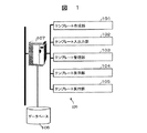
以下、本発明に係る設計業務支援システムの一実施例を、図面を用いて説明する。図1は、設計業務支援システムが備える設計業務支援装置のブロック図である。設計業務支援装置100は、各種演算を実行し、以下に述べるテンプレートに関して制御する計算機107と、今計算機に接続され各種データが格納されたデータベース106と、設計業務支援作業に必要なテンプレートに関するテンプレート作成部101、テンプレート入出力部102、テンプレート管理部103、テンプレート表示部104およびテンプレート実行部105とを備える。
Hereinafter, an embodiment of a design work support system according to the present invention will be described with reference to the drawings. FIG. 1 is a block diagram of a design work support apparatus provided in a design work support system. The design
テンプレート作成部101は、設計業務の手順であるプロセスを作成し、プロセスで利用するアプリケーションソフトを定義するとともに参照すべき情報(以下、ナレッジと呼ぶ)を登録する。テンプレート作成部101はまた、プロセスの順番を定義して、設計業務の手順を定める。
The
テンプレート入出力部102は、テンプレート作成部101で作成したテンプレートや後述するテンプレート実行部105で登録したナレッジ情報を、データベース106に保存するとともにデータベース106からテンプレートを読込む。テンプレート管理部103は、テンプレート作成部101が作成したテンプレートと、定義したプロセス情報およびプロセスの手順情報を管理する。さらに、テンプレート管理部103は、テンプレート入手力部102が読込んだテンプレート情報を管理する。
The template input /
テンプレート表示部104は、テンプレートの情報であるプロセスの並びの情報やナレッジの情報を表示する。テンプレート実行部105は、テンプレートに記載されたプロセス上で定義されたアプリケーションソフトを実行する。また、ナレッジを参照したり、新たに得られたナレッジを登録する。
The
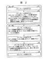
設計業務支援装置100の動作を、図2ないし図10を用いて以下に詳述する。図2は、図1に示した設計業務支援装置100を用いてテンプレートを作成する手順を示すフローチャートであり、図3は図2で作成したテンプレートを用いた設計業務の遂行手順を示すフローチャートである。設計業務支援システムは、大別して2種のフェーズを有する。第1のフェーズでは、設計業務のプロセスを定義し、定義したプロセスで利用するアプリケーションソフトや参照すべきナレッジを定義しプロセスに順番付けするテンプレートを作成する。第2のフェーズでは、作成したテンプレートを用いて設計業務を実行する。
The operation of the design
初めにフェーズ1において、ステップS1で設計手順の詳細が記述されたテンプレートを作成する。この作成するテンプレートの詳細を、図3に示す。本実施例では、テンプレートは6個の手順を含んでいる。なお、各手順の後の括弧書きはプロセス名を示す。
First, in
ステップ31の手順1において、設計仕様を確認する。予め定めた仕様は仕様書の形で設計者に情報(ナレッジ)として提供される。ステップ32の手順2において、設計者は形状モデルの原型を作成する。その際、CADソフトを用いて、CAD操作マニュアルや仕様から導かれる初期の形状図面を参照して形状モデルの原型を作成する。この手順2のプロセスをテンプレート表示部104に表示した例を、図4に示す。
In
表示画面は、左右2つに分かれ、左側には対象とするテンプレート(設計業務)が含む一連のプロセスが表示されている。右側には、現在進行中のプロセス名と、このプロセスで利用可能または利用すべきツールとナレッジが表示されている。具体的には、手順2の「初期形状の作成」が選択されており、この「初期形状の作成」で利用できるまたは利用すべきツール「CADソフト」とナレッジ「CAD操作マニュアル」、「初期形状図面」が表示されている。ここで示したツールやナレッジは、予めデータベース106に登録されている。
The display screen is divided into left and right, and a series of processes included in the target template (design work) is displayed on the left side. On the right is the name of the process currently in progress and the tools and knowledge available or should be used in this process. Specifically, “Create initial shape” in step 2 is selected, and the tool “CAD software” and knowledge “CAD operation manual”, “initial shape” that can be used or should be used in this “create initial shape”. "Drawing" is displayed. The tools and knowledge shown here are registered in the
ステップ33の手順3において、手順2で作成した形状モデルについて構造解析ソフトを用いて強度を判定する。その際、構造解析ソフトのマニュアルや利用可能な複数の解析方法、その解析方法を利用した結果の評価判定方法を随時参照して、最適な解析ソフトを利用するとともに形状モデルを強度面から評価する。
In
ステップ34の手順4において、手順3で得られた形状モデルの原型の強度不足または強度過多の点を改善するために、形状モデルを修正する。その際、これまでに蓄積された同種形状に対する変更または修正ノウハウを参照する。ステップ35の手順5では、手順3と同様の強度計算をして修正された形状モデルについて強度評価する。ステップ36の手順6では、手順5で強度面の評価基準を満足する形状モデルが得られたので、強度に対する影響のない範囲で実物をよりよく近似する形状モデルの修正を施し、形状モデルを最終的に決定する。もちろん、修正が不要の場合には、手順5で使用した形状モデルをそのまま最終形状モデルとして登録する。
In step 4 of
図2のステップS2では、ステップS1で作成したテンプレートをテンプレート入出力部102がデータベース106に保存する。テンプレートを保存するときは、テンプレートの名称(「設計業務」)やテンプレートに記載された複数のプロセスの中で最初に現れるプロセスの名称を、ヘッダファイルとして保存する(1)。一方、個々のプロセスの情報を、プロセスごとに独立したプロセスファイルとして保存する(2)。プロセスファイルには、そのプロセスが所属するテンプレート情報と詳細を後述するプロセスの接続情報を記載する。
In step S <b> 2 of FIG. 2, the template input /
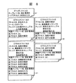
図5に、ヘッダファイル51とプロセスファイル52〜56の例を示す。ヘッダファイル52では、テンプレート名として「設計業務」が、最初に出現するプロセスとして「仕様書の確認」が記載されている。本実施例では図3に示した6個の手順の中から、プロセス内容が重複する強度の検討プロセスを1個にして、プロセスファイル52〜56を5個作成する。 FIG. 5 shows an example of the header file 51 and the process files 52 to 56. In the header file 52, “design work” is described as the template name, and “specification confirmation” is described as the first appearing process. In the present embodiment, five process files 52 to 56 are created from the six procedures shown in FIG.
各プロセスファイルには、プロセス名とそのプロセスで使用するるツールおよびナレッジが記載されている。ここで本発明の特徴である各プロセスの接続関係も、各プロセスファイルに記載している。つまり、プロセスが属するテンプレート名と、このプロセスを実行するときに、このプロセスの直前に実行されたプロセス名とこのプロセスの直後に実行されるプロセス名をも併記している。 Each process file contains the process name and the tools and knowledge used in that process. Here, the connection relationship of each process, which is a feature of the present invention, is also described in each process file. That is, the name of the template to which the process belongs, the name of the process executed immediately before this process and the name of the process executed immediately after this process are also shown.
プロセスファイル52は「仕様書の確認」プロセスであり、所属するテンプレート名に「設計業務」が、前プロセスには「なし」が、後プロセスには「初期形状の作成」が記載されている。この「仕様書の確認」プロセスは、最初に実行されるプロセスなので「なし」が記載される。同様にプロセスファイル56の「形状の決定」プロセスは、最後のプロセスなので、後プロセスには「なし」が記載される。 The process file 52 is a “specification confirmation” process, in which “design work” is described in the template name to which the process belongs, “none” is described in the previous process, and “creation of initial shape” is described in the subsequent process. Since this “specification confirmation” process is the first process to be executed, “none” is described. Similarly, since the “determination of shape” process in the process file 56 is the last process, “none” is described in the subsequent process.
上述したように、「強度の検討」プロセスは、ステップ33の手順3とステップ35の手順5の双方で出現する。この場合の接続情報は、プロセスファイル54に示すように、前後のプロセスを出現順に2度記載する。具体的には、第1回目の出現時(手順3)の前プロセス「初期形状の作成」を最初に記載し、次いで後プロセス「形状の検討」を記載する。次に、2回目の出現(手順5)である前プロセス「形状の検討」を記載し、後プロセス「形状の決定」を最後に記載する。本実施例では、ヘッダファイルを1個、独立したプロセスファイルを5個作成し、データベース106に保存する。
As described above, the “strength review” process appears in both
以上で、フェーズ1の実行が終了する。フェーズ1でテンプレートが作成されたので、このテンプレートを利用して設計作業を実行する(フェーズ2)。ステップS3において、すでに作成されているテンプレートを読込む。その初めに、ヘッダファイルを選択して読込む(1)。ヘッダファイル51とプロセスファイル52〜56とは、ファイルの拡張子を異ならせているので、ヘッダファイルの拡張子を持つファイルの一覧を表示して、所望のファイルを選択する。ヘッダファイルに記載されたトッププロセスの情報を用いて、プロセスファイルを選択して読む(2)。プロセスファイルに記載された接続情報を用いて、設計業務に必要な他のプロセスファイルを読込む。
Thus, execution of
ステップS4において、テンプレートの内容を表示する(1)。表示される画面61、62の一例を図6に示す。図4に示したものと同種の画面である。左側に表示したプロセスの順番は、ヘッダファイルとプロセスファイルに記載されたプロセスの接続情報を用いて、再構成されたものである。この表示画面の中で画面62は、「ナレッジ」の項をクリックしたときにその内容(「CAD操作マニュアル」)を詳細を示すようにしたものである。すなわち、左側画面と右側画面とを問わず、各部をクリックすることにより、その詳細内容が画面上に表示される。 In step S4, the contents of the template are displayed (1). An example of the displayed screens 61 and 62 is shown in FIG. It is the same kind of screen as shown in FIG. The process order displayed on the left side is reconfigured using the connection information of the process described in the header file and the process file. Among the display screens, the screen 62 shows the details (“CAD operation manual”) when the “Knowledge” item is clicked. That is, regardless of the left screen or the right screen, clicking on each part displays the detailed contents on the screen.
ステップS5において、ステップS4に表示されたテンプレートの内容を実行する。ステップS4でテンプレートにおける各ステップの順番が再構成されて表示されているので、その作業内容を表示通りに実行する。ここでは、「設計業務」のプロセスを図3に示したステップ31〜36の順に実行する。その際、プロセス毎に定義されたツールを利用するとともに参照情報を随時表示する(図6参照)。なお、このテンプレートの実行中に新たに得られた情報等は、ナレッジとして登録する。
In step S5, the contents of the template displayed in step S4 are executed. Since the order of each step in the template is reconstructed and displayed in step S4, the work content is executed as displayed. Here, the “design work” process is executed in the order of
ステップS6において、作業を実施したテンプレートを保存する。このテンプレートは、作業前のテンプレートに記載された各プロセスを実行しているときに新たに得られたナレッジを含んでいるので、作業前のテンプレートは異なっていることが多い。そこで、新たなナレッジの登録やプロセスの追加、編集をしてから新規テンプレートとして保存する。保存の際には、ヘッダファイルとプロセスファイルを個々に作成して、データベース106に保存する。
In step S6, the template on which the work has been performed is saved. Since this template includes knowledge newly obtained when each process described in the template before work is executed, the template before work is often different. Therefore, new knowledge is registered, processes are added and edited, and then saved as a new template. When saving, a header file and a process file are individually created and saved in the
本発明の他の実施例として、実行する作業、つまりテンプレートが複数ある場合について、以下に説明する。テンプレートは複数あるが、その実行内容に共通性がある場合である。図3に示した第1のテンプレート「設計業務」と、図7に示した第2のテンプレート「設計業務B」は、共通のプロセスを含んでいる。 As another embodiment of the present invention, an operation to be executed, that is, a case where there are a plurality of templates will be described below. This is a case where there are a plurality of templates, but the execution contents are common. The first template “design work” shown in FIG. 3 and the second template “design work B” shown in FIG. 7 include common processes.
第2のテンプレートは、手順11〜手順14の4個の手順を含んでいる。ステップ71の手順11において、プロセスは「形状の入力」であり、「CAD操作マニュアル」や「入力形状画面」参照しながらCADソフトを用いて、設計者は形状モデルの基本データを入力する。ステップ72の手順12では、「設計業務」テンプレートの手順3、5と同様に作成した形状モデルの強度を評価する。
The second template includes four procedures of procedure 11 to procedure 14. In step 11 of step 71, the process is “input of shape”, and the designer inputs the basic data of the shape model using CAD software while referring to the “CAD operation manual” or “input shape screen”. In step 72 of step 72, the strength of the created shape model is evaluated in the same manner as in
強度評価して良好な結果が得られたので、作成した形状モデルについてステップ73の手順13において振動特性を評価する。振動解析ソフトを用いて、操作方法マニュアルや解析方法、振動評価方法を随時参照して振動特性を評価する。振動特性も良好であれば、ステップ74の手順14において、試作依頼書を作成し試作を担当部署に依頼する。
Since a good result was obtained by evaluating the strength, vibration characteristics are evaluated in step 13 of
この「設計業務B」のテンプレートは、「設計業務」のテンプレートと「強度の検討」のプロセスが共通である。共通のプロセスについては、「設計業務」のテンプレートからコピーして、共通性を保持する。または、すでに登録されたプロセスを一覧表示して、その中から選択してコピーする。 The “design work B” template has the same process as the “design work” template and the “strength review” process. The common process is copied from the “design work” template to maintain commonality. Alternatively, list the processes that have already been registered, and select and copy them.
図8に、設計業務Bに関連するヘッダファイル81とプロセスファイル82〜85を抜き出して示す。プロセスファイル82、84、85に記載のプロセスは、テンプレート「設計業務B」に固有のプロセスであるから、接続関係も「設計業務B」に限られる。一方、プロセスファイル83に記載の「強度の検討」プロセスは、「設計業務」テンプレートでも使用されるプロセスであり、「設計業務B」のテンプレートと「設計業務」のテンプレートの双方のプロセスが接続関係に記載されている。「設計業務B」の接続情報として、前プロセス「形状の入力」と後プロセス「振動の検討」が記載されている。 FIG. 8 shows the header file 81 and process files 82 to 85 extracted from the design work B. Since the processes described in the process files 82, 84, and 85 are processes unique to the template “design work B”, the connection relationship is also limited to “design work B”. On the other hand, the “strength review” process described in the process file 83 is also a process used in the “design work” template, and the processes of both the “design work B” template and the “design work” template are connected. It is described in. As connection information of “design work B”, a pre-process “input of shape” and a post-process “examination of vibration” are described.
本実施例では、データベース106は、2個のヘッダファイル51、81と8個のプロセスファイル52、53、55、56、82〜84を格納している。ここでプロセスファイル83は、2種のテンプレート(「設計業務」「設計業務B」)で使用されるプロセスである。このプロセス「強度の検討」において、ナレッジを追加するなどの変更をしても、本発明によればテンプレート自体を編集しないで、2個のテンプレートのプロセス情報を最新のものに更新できる。
In this embodiment, the
換言すれば、テンプレートは作業手順を示すものであるから、作業手順に変更がない限り、個々のプロセスの内容を変更すればその変更は全てのテンプレートに記載されたプロセスに自動的に反映され、設計者等の作業者がテンプレートを変更する必要がない。プロセスの手順が変更されるときのみ、設計者等はテンプレートを修正する。このように、本実施例によれば、ヘッダファイルとプロセスファイルを用いてプロセス管理しているので、プロセスの内容を変更しても、プロセスが参照しているテンプレートの情報を変更する必要がない。 In other words, since the template indicates the work procedure, unless there is a change in the work procedure, if the content of each process is changed, the change is automatically reflected in the processes described in all templates, There is no need for an operator such as a designer to change the template. Only when the process procedure is changed, the designer modifies the template. As described above, according to this embodiment, since the process is managed using the header file and the process file, it is not necessary to change the information of the template referred to by the process even if the contents of the process are changed. .
本実施例では、ヘッダファイルとプロセスファイルを用いてプロセス管理をしているので、複数のテンプレートに記載された共通のプロセスを抽出し、抽出されたプロセスが記載されたテンプレート(関連テンプレート)を容易にテンプレート表示部104に表示できる。例えば「強度の検討」プロセスを共通プロセスとして抽出すると、プロセスファイル83に接続関係が記載されているので、この接続関係から2種のテンプレート「設計作業」、「設計作業B」が得られる。このテンプレートの相互関係を、図9に示す。
In this embodiment, since process management is performed using a header file and a process file, a common process described in a plurality of templates is extracted, and a template (related template) in which the extracted processes are described can be easily obtained. Can be displayed on the
左列が「設計作業B」のテンプレートに記載されたプロセス71〜74であり、右列が「設計作業」のテンプレートに記載されたプロセス31〜36である。このような一覧表を参照することにより、他のテンプレートにおいて得られた情報や知見等のノウハウを新たなテンプレートに導入することができる。
The left column is the processes 71 to 74 described in the “design work B” template, and the right column is the
上記各実施例で述べたように、1個のプロセスの出力結果は、他のプロセスの入力情報である。すなわち、テンプレート名と、そのテンプレートにおける直前のプロセスおよび直後のプロセスとの関係だけを用いて、プロセスの実行順番を定めている。そこで、異なるテンプレート間の実行順番をも、プロセスファイルに記載すれば、業務全体の流れをもを制御できる。 As described in the above embodiments, the output result of one process is input information of another process. That is, the process execution order is determined using only the relationship between the template name and the immediately preceding process and the immediately following process in the template. Therefore, if the execution order between different templates is also described in the process file, the flow of the entire business can be controlled.
その例を、図10に示す。図10は、上記2種のテンプレート「設計業務」と「設計業務B」とを連続して実行する例である。「設計業務」の最後のプロセス「形状の決定」である手順6で形状を決定した後、「設計業務B」の手順11の「形状の入力」へと移行する場合である。 An example is shown in FIG. FIG. 10 shows an example in which the above two types of templates “design work” and “design work B” are executed in succession. This is a case where after the shape is determined in step 6 which is the final process “determination of shape” of “design work”, the process proceeds to “input of shape” in step 11 of “design work B”.
図5に示したプロセスファイル56は、図10のプロセスファイル110に置き換えられる。この場合、個々のテンプレートはタスクという形で認識されている。つまり、「設計業務」テンプレートは先行タスクであり、「設計業務B」テンプレートは後続タスクである。「設計業務」の前の作業はないものとしているので、先行タスク「なし」のテンプレート表示の後に、後続タスクとして「設計業務B」テンプレート中の「形状の入力」プロセスが記載されている。 The process file 56 shown in FIG. 5 is replaced with the process file 110 shown in FIG. In this case, each template is recognized in the form of a task. That is, the “design work” template is a preceding task, and the “design work B” template is a subsequent task. Since there is no work prior to the “design work”, after the template display of the preceding task “none”, the “shape input” process in the “design work B” template is described as the subsequent task.
同様に、図8に示したプロセスファイル82は、プロセスファイル111に置き換えられる。先行タスクとしてすでに「設計業務」テンプレートが実行されているので、「設計業務」の手順6「形状の決定」プロセスが先行タスク名として記載されている。一方、「設計業務B」テンプレートの後に他のテンプレートを実行することを想定していないので、後続タスクの欄は「なし」と記載されている。 Similarly, the process file 82 shown in FIG. Since the “design work” template has already been executed as the preceding task, the procedure 6 “determine shape” process of “design work” is described as the preceding task name. On the other hand, since it is not assumed that another template is executed after the “design work B” template, “None” is described in the subsequent task column.
このように、先行タスクと後続タスクをプロセスファイル中に記載したので、先行タスクと後続タスクの内容を変更しても、テンプレートにまで遡って内容を変更する必要がない。また、後続タスクで得られたナレッジ(情報)は先行タスクの結果に依存するので、接続情報だけ確実に把握すれば、後続タスクで得られたナレッジであっても、接続関係にある全てのプロセスに得られたナレッジを反映することができる。それとともに、複数のテンプレートにわたるプロセスの影響を表示できる。したがって、あるプロセスに影響を及ぼす他のプロセスの変更を、プロセスの相関とともに示すことができる。 As described above, since the preceding task and the succeeding task are described in the process file, even if the contents of the preceding task and the succeeding task are changed, it is not necessary to change the contents retroactively to the template. In addition, the knowledge (information) obtained in the subsequent task depends on the result of the preceding task, so if only the connection information is reliably grasped, all the processes in the connection relationship even if the knowledge is obtained in the subsequent task The knowledge obtained can be reflected. At the same time, the impact of processes across multiple templates can be displayed. Thus, other process changes that affect a process can be shown along with process correlations.
なお本実施例では、テンプレート数を2としたが、2以上のテンプレートであってもよいことは言うまでもない。また、上記各実施例によれば、プロセスの実行手順をツリー構造で記載することもできる。その場合、プロセスの接続情報に親プロセスと子プロセスの関係情報を含ませればよい。さらに、プロセスの実行手順に分岐や繰り返しの情報を、プロセスの接続情報として含ませることもできる。 In the present embodiment, the number of templates is two, but it goes without saying that two or more templates may be used. Further, according to each of the embodiments described above, the process execution procedure can be described in a tree structure. In this case, the process connection information may include the relationship information between the parent process and the child process. Furthermore, branching and repetition information can be included as process connection information in the process execution procedure.
上記各実施例では、テンプレートの順番付けに、テンプレート名とプロセス名を用いているが、各プロセス単位およびテンプレート単位で付与したID番号等を用いてもよい。ID番号を用いると、異なるテンプレートに同一の名称を付したり、異なるプロセスに同一の名称を付すことが可能になる。また、各プロセスファイルを検索して、複数の接続情報が記載されているものを抽出すれば、共通して使用されるプロセスだけを表示することもできる。 In each of the above embodiments, the template name and the process name are used for ordering the templates. However, an ID number or the like assigned to each process unit and each template unit may be used. If the ID number is used, the same name can be assigned to different templates, or the same name can be assigned to different processes. In addition, if each process file is searched and a file in which a plurality of connection information is described is extracted, it is possible to display only the processes that are used in common.
さらに、各プロセスファイルのデータであるツールやナレッジだけのファイルを作成し、このツールやナレッジのファイルに参照される(使用される)テンプレート名を記載すれば、使用するテンプレートだけにツールやナレッジを容易に表示できる。なお、本設計作業支援システムをネットワーク接続すれば、ヘッダファイルやプロセスファイル、ナレッジなどのデータを分散した環境で利用できる。 Furthermore, if you create a file for only the tool or knowledge that is the data of each process file, and describe the template name referenced (used) in this tool or knowledge file, the tool or knowledge will be added only to the template to be used. It can be displayed easily. If this design work support system is connected to a network, it can be used in an environment where data such as header files, process files, and knowledge are distributed.
100…設計業務支援装置、101…テンプレート作成部、102…テンプレート入出力部、103…テンプレート管理部、104…テンプレート表示部、105…テンプレート実行部、106…データベース、107…計算機。
DESCRIPTION OF
Claims (2)
少なくとも、前記プロセスが実行される直前及び直後のプロセスとの接続関係と、前記プロセスで利用するツールと、が記載されたプロセスファイルが複数保存されたデータベースと、
前記プロセスファイルを読み込むテンプレート入出力部と、
前記テンプレートに記載された前記複数のプロセスを順番に実行させるとともに、前記読み込んだプロセスファイルに記載された接続関係に基づいて、前記ツールを実行させるテンプレート実行部とを備え、
前記プロセスファイルには、複数の前記接続関係が記載されたことを特徴とする設計業務支援装置。 A template creation unit for creating a plurality of processes that are procedures of design work and creating a template in which the order of the plurality of processes is described ;
A database in which a plurality of process files storing at least a connection relationship with a process immediately before and after the process is executed and a tool used in the process are stored ;
A template input / output unit for reading the process file ;
A template execution unit that sequentially executes the plurality of processes described in the template and that executes the tool based on the connection relationship described in the read process file;
A design work support apparatus , wherein a plurality of the connection relationships are described in the process file .
少なくとも、前記テンプレートと、前記ツールとを画面に表示させるテンプレート表示部を備えたことを特徴とする設計業務支援装置。 The design work support apparatus according to claim 1,
A design work support apparatus comprising a template display unit for displaying at least the template and the tool on a screen .
Priority Applications (1)
| Application Number | Priority Date | Filing Date | Title |
|---|---|---|---|
| JP2004061530A JP4352941B2 (en) | 2004-03-05 | 2004-03-05 | Design work support device |
Applications Claiming Priority (1)
| Application Number | Priority Date | Filing Date | Title |
|---|---|---|---|
| JP2004061530A JP4352941B2 (en) | 2004-03-05 | 2004-03-05 | Design work support device |
Publications (2)
| Publication Number | Publication Date |
|---|---|
| JP2005250919A JP2005250919A (en) | 2005-09-15 |
| JP4352941B2 true JP4352941B2 (en) | 2009-10-28 |
Family
ID=35031335
Family Applications (1)
| Application Number | Title | Priority Date | Filing Date |
|---|---|---|---|
| JP2004061530A Expired - Fee Related JP4352941B2 (en) | 2004-03-05 | 2004-03-05 | Design work support device |
Country Status (1)
| Country | Link |
|---|---|
| JP (1) | JP4352941B2 (en) |
Families Citing this family (1)
| Publication number | Priority date | Publication date | Assignee | Title |
|---|---|---|---|---|
| JP2008181232A (en) * | 2007-01-23 | 2008-08-07 | Hitachi Ltd | System and method for supporting design work |
-
2004
- 2004-03-05 JP JP2004061530A patent/JP4352941B2/en not_active Expired - Fee Related
Also Published As
| Publication number | Publication date |
|---|---|
| JP2005250919A (en) | 2005-09-15 |
Similar Documents
| Publication | Publication Date | Title |
|---|---|---|
| US11003805B2 (en) | Cognitive system for computer aided design | |
| JP4759580B2 (en) | Plant construction simulation data creation method and system | |
| EP1302904B1 (en) | Object modeling | |
| JPH05205012A (en) | Method of changing cad data | |
| KR102279061B1 (en) | Methdo for Optimizing Analysed Model based on Lightweight Models | |
| CN102177518B (en) | Method and device for producing a finite element model | |
| JP5026925B2 (en) | Control program creation device and control program creation method | |
| JP3985467B2 (en) | Design support system and design support method | |
| JP4069701B2 (en) | Work support device | |
| JPH1139145A (en) | Device to support programming and storage medium | |
| JP4102137B2 (en) | Control program creation support system and support method thereof | |
| JP2003150650A (en) | Analysis work support device, and program for realizing analysis work support function | |
| Zahedi et al. | Utilization of simulation tools in early design phases through adaptive detailing strategies | |
| US20070010984A1 (en) | CAE Analysis Navigation System, CAE Analysis Processing Program, and Recording Medium Recording CAE Analysis Processing Program | |
| JP4352941B2 (en) | Design work support device | |
| JP4902567B2 (en) | Work procedure manual creation system and work procedure manual creation program | |
| US8990050B2 (en) | Systems and methods of updating graphical objects | |
| US20220180011A1 (en) | Systems and methods for modifying cad files | |
| JP2003316829A (en) | Design operation support device | |
| JP4583260B2 (en) | General-purpose computer operation procedure creation device, program, and storage medium | |
| JP5084702B2 (en) | Analysis data input device, CAE device, analysis data input method, and program | |
| JP4374008B2 (en) | General-purpose analysis system | |
| JP2004310317A (en) | Business support device | |
| JP2002169843A (en) | Design support system | |
| JPH06332909A (en) | Plan managing system |
Legal Events
| Date | Code | Title | Description |
|---|---|---|---|
| A621 | Written request for application examination |
Free format text: JAPANESE INTERMEDIATE CODE: A621 Effective date: 20060123 |
|
| RD04 | Notification of resignation of power of attorney |
Free format text: JAPANESE INTERMEDIATE CODE: A7424 Effective date: 20060424 |
|
| A131 | Notification of reasons for refusal |
Free format text: JAPANESE INTERMEDIATE CODE: A131 Effective date: 20090224 |
|
| A521 | Request for written amendment filed |
Free format text: JAPANESE INTERMEDIATE CODE: A523 Effective date: 20090420 |
|
| RD02 | Notification of acceptance of power of attorney |
Free format text: JAPANESE INTERMEDIATE CODE: A7422 Effective date: 20090420 |
|
| TRDD | Decision of grant or rejection written | ||
| A01 | Written decision to grant a patent or to grant a registration (utility model) |
Free format text: JAPANESE INTERMEDIATE CODE: A01 Effective date: 20090707 |
|
| A01 | Written decision to grant a patent or to grant a registration (utility model) |
Free format text: JAPANESE INTERMEDIATE CODE: A01 |
|
| A61 | First payment of annual fees (during grant procedure) |
Free format text: JAPANESE INTERMEDIATE CODE: A61 Effective date: 20090720 |
|
| R151 | Written notification of patent or utility model registration |
Ref document number: 4352941 Country of ref document: JP Free format text: JAPANESE INTERMEDIATE CODE: R151 |
|
| FPAY | Renewal fee payment (event date is renewal date of database) |
Free format text: PAYMENT UNTIL: 20120807 Year of fee payment: 3 |
|
| FPAY | Renewal fee payment (event date is renewal date of database) |
Free format text: PAYMENT UNTIL: 20120807 Year of fee payment: 3 |
|
| FPAY | Renewal fee payment (event date is renewal date of database) |
Free format text: PAYMENT UNTIL: 20130807 Year of fee payment: 4 |
|
| LAPS | Cancellation because of no payment of annual fees |