EP1302904B1 - Object modeling - Google Patents
Object modeling Download PDFInfo
- Publication number
- EP1302904B1 EP1302904B1 EP02292539A EP02292539A EP1302904B1 EP 1302904 B1 EP1302904 B1 EP 1302904B1 EP 02292539 A EP02292539 A EP 02292539A EP 02292539 A EP02292539 A EP 02292539A EP 1302904 B1 EP1302904 B1 EP 1302904B1
- Authority
- EP
- European Patent Office
- Prior art keywords
- feature
- model
- scope
- features
- objects
- Prior art date
- Legal status (The legal status is an assumption and is not a legal conclusion. Google has not performed a legal analysis and makes no representation as to the accuracy of the status listed.)
- Expired - Lifetime
Links
- 239000000463 material Substances 0.000 claims description 77
- 238000013461 design Methods 0.000 claims description 76
- 238000000034 method Methods 0.000 claims description 53
- 230000008569 process Effects 0.000 claims description 13
- 238000005094 computer simulation Methods 0.000 claims description 12
- 238000013500 data storage Methods 0.000 claims description 11
- 230000008929 regeneration Effects 0.000 claims description 10
- 238000011069 regeneration method Methods 0.000 claims description 10
- 230000000694 effects Effects 0.000 claims description 8
- 238000012545 processing Methods 0.000 claims description 6
- 238000010276 construction Methods 0.000 claims description 4
- 238000005520 cutting process Methods 0.000 claims description 4
- 238000011960 computer-aided design Methods 0.000 description 20
- 239000007787 solid Substances 0.000 description 15
- 238000004519 manufacturing process Methods 0.000 description 9
- 239000002131 composite material Substances 0.000 description 7
- 230000003993 interaction Effects 0.000 description 5
- 238000003860 storage Methods 0.000 description 5
- 238000004590 computer program Methods 0.000 description 4
- 230000004048 modification Effects 0.000 description 4
- 238000012986 modification Methods 0.000 description 4
- 230000001052 transient effect Effects 0.000 description 4
- 230000008859 change Effects 0.000 description 3
- 230000009471 action Effects 0.000 description 2
- 238000004458 analytical method Methods 0.000 description 2
- 230000008901 benefit Effects 0.000 description 2
- 238000004422 calculation algorithm Methods 0.000 description 2
- 230000001419 dependent effect Effects 0.000 description 2
- 230000006870 function Effects 0.000 description 2
- 230000002452 interceptive effect Effects 0.000 description 2
- 238000003754 machining Methods 0.000 description 2
- 238000007726 management method Methods 0.000 description 2
- 230000007246 mechanism Effects 0.000 description 2
- 238000013459 approach Methods 0.000 description 1
- 230000006399 behavior Effects 0.000 description 1
- 230000009286 beneficial effect Effects 0.000 description 1
- 238000004364 calculation method Methods 0.000 description 1
- 238000004891 communication Methods 0.000 description 1
- 230000003247 decreasing effect Effects 0.000 description 1
- 238000012938 design process Methods 0.000 description 1
- 238000010586 diagram Methods 0.000 description 1
- 238000005516 engineering process Methods 0.000 description 1
- 238000001125 extrusion Methods 0.000 description 1
- 230000007935 neutral effect Effects 0.000 description 1
- 238000005457 optimization Methods 0.000 description 1
- 230000001172 regenerating effect Effects 0.000 description 1
- 230000004044 response Effects 0.000 description 1
- 230000000717 retained effect Effects 0.000 description 1
- 239000004065 semiconductor Substances 0.000 description 1
- 230000000007 visual effect Effects 0.000 description 1
- 239000011800 void material Substances 0.000 description 1
Images


Classifications
-
- G—PHYSICS
- G06—COMPUTING; CALCULATING OR COUNTING
- G06T—IMAGE DATA PROCESSING OR GENERATION, IN GENERAL
- G06T17/00—Three dimensional [3D] modelling, e.g. data description of 3D objects
- G06T17/10—Constructive solid geometry [CSG] using solid primitives, e.g. cylinders, cubes
Definitions
- CAD software allows a user to construct and manipulate complex three-dimensional (3D) models of assembly designs.
- a number of different modeling techniques can be used to create a model of an assembly. These techniques include solid modeling, wire-frame modeling, and surface modeling.
- Solid modeling techniques provide for topological 3D models, where the 3D model is a collection of interconnected edges and faces, for example. Geometrically, a 3D solid model is a collection of trimmed surfaces. The trimmed surfaces correspond to the topological faces bounded by the edges.
- Wire-frame modeling techniques can be used to represent a model as a collection of simple 3D lines, whereas surface modeling can be used to represent a model as a collection of exterior surfaces.
- CAD systems may combine these, and other, modeling techniques, such as parametric modeling techniques.
- Parametric modeling techniques can be used to define various parameters for different features and components of a model, and to define relationships between those features and components based on relationships between the various parameters.
- Solid modeling and parametric modeling can be combined in CAD systems supporting parametric solid modeling.
- a design engineer is a typical user of a 3D CAD system.
- the design engineer designs physical and aesthetic aspects of 3D models, and is skilled in 3D modeling techniques.
- the design engineer creates parts and may assemble the parts into one or more subassemblies.
- a subassembly may also consist of other subassemblies.
- the design engineer designs an assembly.
- parts and subassemblies are collectively referred to as components.
- a part is constructed using various geometric building blocks.
- Geometric building blocks hereinafter referred to as features, may be constructed by first creating a two-dimensional profile and extruding that profile into a three-dimensional object.
- Features may be divided into two primary categories. The two primary categories are features used to add material to a part, such as a boss, and features used to subtract material from a part, such as a cut.
- a design engineer creates features while constructing a part affects the physical structure of that part in a feature-based CAD system. For example, a part constructed first by cutting a block with a cylinder and then adding a boss that extends inside the void left by the cut cylinder will result in a hole with material from the boss inside the hole. If the order of the operations were reversed such that the boss was added before the cylindrical cut, then the cut would not only cut the material of the original block, but also that of the subsequent boss, resulting in a hole with no material inside of it.
- a feature acts on all features that have been previously included in the model and has no effect on features subsequently introduced to the model.
- feature-based modeling systems are also history-based modeling system. The design engineer is required to control the scope of a feature by manipulating the feature's location in the overall historical order of features.
- Commercially available feature-based modeling systems include the SolidWorks® 2001 Plus software system available from SolidWorks Corporation of Concord, Massachusetts.
- History-based CAD systems that define components as a sequence of simple feature operations work on the same principal.
- the data e.g., points, lines, and dimensions
- the component keeps an ordered list of these features.
- Each feature has a corresponding regeneration algorithm that takes the feature data and the geometry resulting from the previous features in the ordered list and modifies the geometry according to the feature's definition (e.g., make a cut of a certain shape at a certain location).
- the user typically will add features one by one to the component's feature list.
- the user simply changes the feature's data and then the system recreates the component by deleting the old resulting geometry and regenerating each feature one by one in the order in which the user originally specified the features.
- the user's feature creation order is identical to the internal feature regeneration order.
- One way in which the definition of a part may be modified is to redesign the features that define the part. Those features that were introduced in an order that caused the geometry to be generated incorrectly may need to be deleted and re-created in an order that causes the geometry to be generated correctly. Thus, the design engineer must spend additional time defining the same feature again.
- a CAD system may keep track of the feature history and present the history to the design engineer as a hierarchical collection of features.
- the feature history may be presented in a window (or a section of the window) generated by the CAD system.
- the design engineer may be able to rearrange the collection of features by dragging a depiction of a feature to a different position in the hierarchical collection, and thereby modify the feature history for a part.
- U.S. Patent No. 5,815,154 to Hirschtick et al discloses a system for modifying a model by allowing a user to graphically manipulate a hierarchical collection of features.
- design engineers may decide that re-designing the part is too time-consuming.
- a design engineer may find that the incorrect geometry can be easily corrected by adding a cut that is identical to another cut. Although the identical cut is redundant, the geometry is corrected quickly without re-ordering the features in a part.
- CAD system may provide a feature management tool to help a design engineer rearrange the history of features included in a part, the design engineer is encumbered with analyzing the feature history and re-ordering the features in the part hierarchy as necessary to ensure that the part is geometrically correct.
- a design engineer who intends to become skilled in 3D feature-based modeling needs to become proficient in ordering features. Learning how best to introduce features is part of the experience necessary for becoming skilled in the art of 3D feature-based modeling.
- features may be dependent on other features.
- the position of one hole may depend on the position of a second hole.
- This type of geometric dependency may be defined by establishing a parametric relationship between the two holes.
- the value of an attribute of one feature in the parametric relationship is modified, the value of an attribute of another feature in the parametric relationship may be automatically modified in response.
- a design engineer intends that a parametric relationship be preserved when re-ordering the hierarchical structure of a part. The burden is placed on the design engineer first to be aware of the dependencies and second to ensure that they are preserved (perhaps by re-establishing the dependencies if the dependencies are severed during a re-ordering process).
- Document US-A-6 256 596 discloses a flexible framework within a CAD application program. This document relates to handling feature information in a parametric feature-based solid modeler, and in particular, to a method for providing an extensible framework for capturing feature information in a neutral format. This document is however not concerned with the modeling of a three-dimensional object but is concerned with improving the techniques to access CAD designed part data.
- Systems and methods for defining a scope of a feature include storing data that defines features of a computer model and forming a feature chain with at least one feature object.
- the feature object has a design effect limited in scope such that an operation for removing material operates to affect another feature object in the same feature chain and does not affect feature objects in another feature chain.
- Feature chains are combined and form an interrelationship among feature objects that represents a hierarchy, which defines the construction of the model from the feature objects.
- an unordered feature list comprising the plurality of feature objects is read, at least one feature object that adds material to the computer model is located, and at least one feature object that removes material from the computer model and is associated by a scope definition with the feature object that adds material is located.
- a feature object that removes material can have a never-fill attribute to indicate a cutting effect on each feature object that adds material.
- Further aspects include optimizing the feature chains and inputting the combination of the feature chains, which prescribes the regeneration order, into a process that generates a part.
- the scope definition can be based on feature object existence, on feature object proximity, or on a combination of feature object existence and feature object proximity. Implementations can enable the user to issue an instruction to modify the scope definition, whereby the instruction explicitly specifies either a feature object to include in the scope definition or a feature object to exclude from the scope definition.
- a user interface dialog can facilitate the explicit specification of the scope definition.
- the present invention allows design engineers to design components without worrying about feature order. This is achieved by separating the concepts of feature creation order and feature regeneration order. Therefore, the order in which a user adds features to a component is independent of the order in which the geometric feature operations (e.g., applying a boss or applying a cut) are applied to the underlying geometric model.
- the present invention provides a mechanism that automatically determines feature regeneration order independent of the user's feature creation order. Such an automated mechanism saves the design engineer an enormous amount of time and effort during the 3D modeling process because he or she is freed from redesigning parts and/or manipulating the order of features to correct geometry.
- the present invention controls the regeneration order, which not only takes a large burden off the user, but also adds beneficial dynamic qualities overall to a feature-based modeling system.
- the present invention enables design engineers to construct featured-based models without excessive consideration to the order in which the features are defined. Rather than requiring a design engineer to rely on feature order to control the final geometric representation of a part, the present invention builds data structures that group features and automatically modifies the groupings as needed. The groupings may be modified when the design engineer indicates the scope upon which a feature should act (i.e., explicit scope), when certain attributes of the feature indicate an implicit scope, or when a combination of explicit and implicit scope so indicates.
- the present invention gives the design engineer additional controls over the final shape of a part, and enhances the flexibility and functionality of a computerized modeling system.
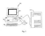
- FIG. 1 shows a computerized modeling system 100 that includes a CPU 102, a CRT 104, a keyboard input device 106, a mouse input device 108, and a storage device 110.
- the CPU 102, CRT 104, keyboard 106, mouse 108, and storage device 110 can include commonly available computer hardware devices.
- the CPU 102 can include a Pentium-based processor.
- the mouse 108 may have conventional left and right buttons that the user may press to issue a command to a software program being executed by the CPU 102.
- Other appropriate computer hardware platforms are suitable as will become apparent from the discussion that follows. Such computer hardware platforms are preferably capable of operating the Microsoft Windows NT, Windows 95, Windows 98, Windows 2000, Windows XP, Windows ME, or UNIX operating systems.
- Computer-aided design software is stored on the storage device 110 and is loaded into and executed by the CPU 102.
- the software allows the design engineer to create and modify a 3D model and implements aspects of the invention described herein.
- the CPU 102 uses the CRT 104 to display a 3D model and other aspects thereof as described later in more detail.
- a design engineer can enter and modify data associated with the 3D model.
- the CPU 102 accepts and processes input from the keyboard 106 and mouse 108.
- the CPU 102 processes the input along with the data associated with the 3D model and makes corresponding and appropriate changes to that which is displayed on the CRT 104 as commanded by the modeling software.
- Additional computer processing units and hardware devices may be included in the computerized modeling system 100.
- the computerized modeling system 100 may include network hardware and software thereby enabling communication to a hardware platform 112.
- the invention could also be used in conjunction with other computer-aided design software that addresses applications other than mechanical design.
- a computer-aided modeling system may have the capability of retaining a design engineer's original design intent as a model undergoes modifications before the model design is complete.
- a parametric modeling system (or a parametric solid modeling system), ensures that certain aspects of the design engineer's intent are retained.
- the underlying data structures of the modeling software behave parametrically. For example, the geometry, display attributes, and annotations displayed as part of the model on the CRT 104 are updated as needed when a design engineer changes the model.
- the modeling system is a solid modeling system.
- the model may be an assembly of solid model components or simply a part.
- the solid model may have relationships that parametrically constrain the definitions of one or more components or features with respect to one another. If a parametrically constrained relationship exists between two features, a geometric modification to one feature may cause a geometric modification in the other feature.
- the present invention may preserve parametric relationships in the reorganized part structure by using computational resources to analyze the dependencies when ordering features and ensuring that the dependencies are maintained.
- FIG. 2 shows a window 202 displayed on the CRT 104 and generated by a CAD software system.
- the window 202 is a conventional computer-generated window that can be programmed by one of ordinary skill in the art using conventional, commercially available, software programming tools, such as those available from Microsoft Corporation of Redmond, Washington.
- a computer-generated 3D model 204 is displayed within a modeling portion 206 of the window 202.
- the design engineer can construct and modify the 3D model 204 in a conventional manner.
- the surfaces of the 3D model 204 can be displayed, or the 3D model 204 can be displayed using solid lines and dashed lines to show visible edges and hidden edges, respectively, of the 3D model.
- Implementations also may include other window areas, such as an order independent list of features 208, which helps the design engineer visualize and manipulate the model 204 shown in the modeling portion 206.
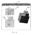
- FIG. 3 shows a window 302 that contains three views of a part under construction.
- the top view 304, front view 306, and rotated view 308 reveal that the part is partially defined by two block features (i.e., upper block 312 and lower block 314). Additionally, the top view 304 and the front view 306 plainly show an extruded profile 310 of a circle. The purpose of the extruded profile 310 is to create a cylindrical cut feature in the part.
- FIG. 4 shows the window 302 after the extruded profile 310 was used to construct a cut feature 402.
- the cut 402 was created by subtracting material that was located within the extruded profile 310 from the upper block 312 and the lower block 314.
- the cut 402 would appear as illustrated in FIG. 4 in a CAD system that is based on feature existence if the upper block 312 and the lower block 314 were included in the part definition (i.e., existed) prior to the inclusion of cut feature 402.
- FIG. 5 shows the window 302 containing a part in which a cut feature 502 did not subtract material from the upper block 312.
- the cut 502 may appear as illustrated in FIG. 5 in a CAD system that is based on feature existence if the lower block 314 was included in the part definition first, the cut feature 502 was included in the part definition second, and the upper block 312 was included in the part definition third. Therefore, the scope of the cut 502 is the lower block 314 only.
- the present invention allows a design engineer to explicitly specify one or more features on which a particular feature acts. This enables the design engineer to include a feature in or exclude a feature from the scope of a particular feature.
- feature scope the collection of features on which another feature acts.
- a feature has explicit feature scope if that feature removes material from another feature as instructed by a design engineer.
- the present invention enables the design engineer to include the upper block 312 and the lower block 314 in the part definition prior to introducing the cut feature 502, then indicate that the feature scope of the cut feature 502 is lower block 314 only, thereby constructing the part shown in FIG. 5 .
- the design engineer may discover that the part is physically incorrect due to the order in which features were introduced during the design process.
- the present invention enables the design engineer to specify the explicit scope of a feature.
- a user interface command may facilitate the specification of explicit scope of a feature, as will be discussed.
- a feature may also have implicit feature scope.
- implicit feature scope is when a feature removes material from an existing feature without being instructed to do so by the design engineer. This may occur due to the order in which a feature was introduced to a part and/or due to a proximity calculation wherein the physical extent of a feature determines the implicit feature scope.
- Another example of implicit feature scope is when a first feature removes or does not remove material from a second feature based on an attribute of the first or second feature.
- Such implicit scope results, by way of non-limiting example, when a cut is defined with a "never-fill" attribute that prevents any feature that adds material to fill the cut with material.
- a boss i.e., any feature that adds material
- a "never-fill" attribute may be overridden by certain actions. Such an action may occur when a user specifically instructs the modeling system to override the "never-fill" attribute for a particular feature or a collection of features (e.g., a pocket feature constructed from more than one feature).
- Implicit and explicit feature scopes are not mutually exclusive. That is, although the system may implicitly determine a feature's scope, the design engineer would subsequently be able to explicitly modify the system-determined feature scope and even redefine the feature scope entirely.
- upper block 312 and lower block 314 may be included explicitly in the feature scope of cut 402 if the design engineer instructs the system to apply the cut 402 to the upper block 312 and the lower block 314.
- One way in which a design engineer may specify explicit feature scope is for the CAD system to provide a user interface command that enables the design engineer to select the cut 402 then select the block or blocks on which the cut 402 should act.
- the user interface contains a command for specifying the explicit scope of a feature.
- the design engineer may first select one feature that removes material from the part, then may select one or more features that add material to the part, then indicate that the selection is complete.
- the design engineer may first select one or more features that add material to the part, then may select one feature that removes material from the part, then indicate that the selection is complete.
- the present invention analyzes the selected features and determines whether a feature that removes material was selected first or whether one or more features that add material were selected first. When a feature that removes material is selected prior to the selection of features that add material, the selected features that add material are automatically added to the feature scope of the selected feature that removes material from the part.
- the features that add material to the part are automatically excluded from the feature scope of the feature that removes material from the part.
- the behavior of the user interface command depends on which type of feature was selected first.
- the user interface in an embodiment may also display a dialog box to facilitate the specification of feature scope.
- the dialog box may list features belonging to the feature scope of a particular feature and allow the design engineer to add or remove features from the feature scope list.
- the CAD system may provide graphical feedback by highlighting, in the modeling portion of a window, those features belonging to the feature scope.
- the design engineer may also be allowed to pick features in the modeling portion of the window to add and remove from the feature scope, such that an associative relationship exists between the features as listed in the dialog box and as displayed in the modeling portion of the window.
- the feature scope of the cut 402 is the upper block 312 and the lower block 314. This scope may be determined implicitly based on the features that exist at the time of feature creation, that is, block 312 and block 314 may be included implicitly in the feature scope of cut 402 because cut 402 was included in the part after the inclusion of upper block 312 and lower block 314. A boss added subsequently, however, would not be included implicitly in the scope of cut 402.
- Implicit feature scope may also be determined by proximity in combination with prior existence of a feature.
- the feature scope of a feature that removes material includes any feature that adds material and that volumetrically interferes with the feature that removes material.
- Another pre-existing feature that adds material that is outside the volume of the cutting area is excluded from the feature scope of the feature that removes material.
- a combination of prior existence of a feature and geometry proximity as well as other feature-feature relationships can be used to determine implicit feature scopes.
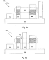
- a part 600 consisting of five bosses (602-610) and a cylindrical cut 612 is shown.
- the feature scope of the cylindrical cut 612 is all bosses that existed prior to the definition of the cylindrical cut 612 and volumetrically interferes with the cylindrical cut 612.
- bosses 602-610 existed prior to cylindrical cut 612
- the feature scope of cylindrical cut 612 is boss 606 and boss 608 because boss 606 and boss 608 are within the extent of the cylindrical cut 612.
- the part 600 is modified such that boss 610 is positioned between boss 606 and boss 608.
- the feature scope of the cylindrical cut 612 is not modified.
- the feature scope of cylindrical cut 612 is not modified because in this embodiment the proximity and pre-existence criteria for determining feature scope are applied at the time of feature creation (and not at subsequent re-generations of the part) and serve as a basis for the feature scope.
- the feature scope is under the design engineer's control.
- boss 610 would be included in the feature scope of cylindrical cut 612 after being moved.
- An aspect of the present invention dynamically groups and orders features, and determines how groupings of features should be combined.
- the groupings and the order of features in each grouping are determined by feature scope.
- a grouping of features is hereinafter referred to as a "feature chain.”
- features belonging to the same feature chain may be combined using Boolean operations. Additionally, one or more feature chains may then be combined to produce the final shape of a part. One feature chain may always exist to consolidate all other feature chains.
- a feature chain maintains three volumes.
- the first volume is a positive volume that combines all features that add material.
- the second volume is a negative volume that combines all features that remove material.
- the third volume combines the positive and negative volumes.
- Simple feature chains always have one feature that adds material and zero or more features that remove material.
- a composite feature chain can have one or more features or feature chains that add material, and one or more features or feature chains that remove material.
- a feature chain generator builds simple feature chains whenever a feature is added, a feature is removed, a feature scope is modified, or a shell definition is modified.
- Composite feature chains are formed from simple feature chains and then may be input to an optimization process.
- Either simple feature chains or optimized composite feature chains are used as input to a rebuild engine, which constructs the part.
- the feature chains specify the feature order to the rebuild engine, opposed to conventional history-based modeling systems where the user was solely responsible for specifying order.
- the procedure 700 reads an unordered feature list 702.
- the unordered feature list is created when the design engineer first defines a feature and is updated as additional features are defined and when features are deleted.
- the procedure 700 determines if a feature adds material to a part 704. If the feature adds material to the part, a simple feature chain is created and the feature is included as the positive volume (and the first feature) in the simple feature chain 706.
- the procedure 700 locates all features that remove material. Thus, the procedure 700 may read the unordered feature list again 708. The procedure 700 determines if a feature removes material 710, and if so, determines the feature scope of that feature. Data in the form of feature scope and never-fill indicators is associated with all features that remove material to aid in the determination. The procedure 700 determines if the feature is a cut having a "never-fill" attribute 712, and if the feature is, the feature is included in each simple feature chain 714.
- the "never-fill" cut is added to the composite feature chain only. If the feature is a feature that removes material but is not a cut having a "never-fill” attribute, then the feature scope for that feature is examined. The feature is then included as the negative volume in all simple feature chains having as the positive volume the features in the feature scope 716.
- procedure 700 When the procedure 700 has located all features that remove material, a composite feature chain is created to combine all feature chains 718. A Boolean union operation may be performed to combine all feature chains. After the feature chains are combined, procedure 700 completes.
- FIG. 8 an illustration of data and procedures that may be used in an implementation of the present invention is shown.
- data in the form of an unordered feature list 802 and for those features that remove material, data in the form of feature scope / never-fill indicators 804 is input to the feature chain generator 806.
- the feature chain generator 806 groups and orders features from the unordered feature list 802 in view of the feature scope / never-fill indicators 804, as previously discussed.
- the output from the feature chain generator is transient feature chain data 808.
- the transient feature chain data 808 may be used as input to an optimizer 810. (Otherwise, the transient feature chain data 808 is directly input to the rebuild engine 814.)
- the function of the optimizer 810 is to reduce the size of the feature chain and allow for more efficient processing of the feature chain data. Reducing the size of the feature chain allows for more efficient processing because the number of times a feature needs to be processed is decreased.
- Optimized transient feature chain data 812 is output from the optimizer 810 and used as input to a rebuild engine 814.
- the rebuild engine 814 rebuilds the features individually based on the design engineer's input parameters and construction geometry that are stored with the data that defines the features.
- the present invention may use a rebuild engine such as that described in U.S. Patent No. 5,815,154 to Hirschtick et al.
- the output of the rebuild engine 814 is a part 816.
- the part may consist of geometry (e.g., vertices, edges, faces, and surfaces), and/or may consist of solid bodies in the case where solid features such as extrusions and fillets were used to define the part. Additionally, a feature may be a two-dimensional feature.
- feature chains may be rebuilt by separate threads or processors in a multi-processor computerized modeling system. Therefore, the performance of the present invention may increase in scale with the number of processors available in the computerized modeling system.
- a simple feature chain is built beginning with a feature that adds material followed by all features that remove material from the feature that adds material.
- the upper block 312 and lower block 314 shown in FIG. 4 add material, whereas the cut 402 removes material. Therefore, a first simple feature chain F1 beginning with upper block 312 and a second simple feature chain F2 beginning with lower block 314 is built, and both of these feature chains include cut 402. Additionally, a composite feature chain F3 would be constructed for the purpose of combining the first two feature chains.
- the feature chains that generate the part shown in FIG. 4 may be represented as follows:
- the positive volumes of a feature chain are to the right of the equal sign and to the left of the "
- ” character denotes the combination of the positive and negative volumes in the feature chain.
- the third volume is denoted by the characters on the left side of the equation.
- the chains may be optimized to reduce the size of the part definition and to increase the efficiency of computing resources. Consolidating all feature chains having identical features that remove material is one way feature chains may be optimized.
- feature chains F1, F2 and F3 may be combined as follows:
- a tree-like visual representation (referred to as a feature tree 900), of the feature chain F4 is shown.
- the union operator 902 combines the upper block 312 and the lower block 314 (depicted by nodes 906 and 908, respectively).
- the subtraction operator 904 subtracts the cut 402 (depicted by node 910), from the union of the upper block 312 and the lower block 314.
- the operation 904 is a parent operation to child operations 902 and 910
- the operation 902 is a parent operation to child operations 906 and 908.
- feature chains may also be considered features and used in other chains.
- a chain that only contains one feature (or one chain) is optimized by adding the feature to the final chain. For example, if a side block were added to the part in the foregoing example, an un-optimized feature chain F5 with one feature that is the side block and an optimized final feature chain F6 may be represented as follows:
- the part illustrated in FIG. 5 contains a cut feature 502. Possibly, the design engineer defined lower block 314 first, followed by cut 502, and then upper block 312. If implicit scope is determined by feature existence, in this case, the cut 502 has implicit scope to act only upon lower block 314 because cut 502 was defined after lower block 314 and before upper block 312.
- the feature chains that represent the part illustrated in FIG. 5 may be represented as follows:
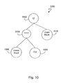
- FIG. 10 a feature tree 1000 that represents the feature chain for the part illustrated in FIG. 5 is shown.
- the subtraction operator 1004 has the effect of removing the material defined by the cut 502 (depicted as node 1008) from lower block 314 (depicted as node 1006).
- the union operator 1002 combines the result of the subtraction operation with the upper block 312 (depicted as node 1010).
- the part illustrated in FIG. 5 would appear as the part illustrated in FIG. 4 if the feature scope is not ultimately determined by the pre-existence of features.
- a different implicit scope may be associated with cut 502 if a "never-fill" attribute was specified for the cut 502 when the cut 502 was created, resulting in an implicit scope such that every feature that adds material is affected by the cut 502 in such a way that the cut 502 could never be filled by any feature that adds material.
- Cuts having a "never-fill” attribute are added to the negative volume in the final feature chain.
- the part illustrated in FIG. 5 would also appear as the part illustrated in FIG. 4 if an explicit scope is specified after all the features were defined by, for example, using a feature scope command provided in the user interface, as was previously discussed.
- Feature chains are automatically re-created to re-group and re-order features as necessary when explicit feature scope is specified.
- the window 302 containing three views of a part 1100 is shown.
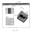
- the part was created by shelling a block feature (meaning that the block feature was hollowed), then applying a cylindrical cut 1102 to the hollowed block feature.
- the design engineer may specify a face to be removed, in addition to the thickness of the wall of the shell.
- a rectangular face is removed to reveal the inside of the part 1100.
- An inward shell operation offsets the original faces of a solid in an inward direction and constructs new shell faces on the inside of the part.
- An outward shell operation offsets the original faces in an outward direction, leaving the inverted original faces on the inside of the part and constructing new shell faces on the outside of the part.
- An outward shell operation grows the part in overall size, whereas the part remains the same overall size after the inward shell operation completes.
- the inward shell operation is a two-part operation. First, the faces of the features that define the shell are offset inward in a standard offset operation. The result of the offset operation is a solid that is then subtracted from the original solid leaving the final shelled result.
- a procedure to create an outward shell is also comprised of two distinct operations. The first operation offsets the original body outward. The second operation subtracts the original body from the offset body. Parts may have multiple shelling features that affect various subsets of features within a part.
- a first chain F1 consisting of only a block is created.
- the block feature that defines the shell forms feature chain F2.
- An inward offset operation is applied to the result of F2 to form O1 (i.e., the offset body).
- O1 i.e., the offset body
- the offset O1 is subtracted from F1 resulting in F3.
- the cylindrical cut is subtracted from F3 to form the feature chain F4.
- FIG. 12 is a feature tree representation 1200 of the preceding feature chains.
- Node 1204 and node 1208 represent the block, which is identical, in F1 and F2.
- Node 1206 represents the offset operation, and together with node 1208 depicts the feature chain O1.
- Node 1202 represents a subtraction operation and forms the feature chain F3 by subtracting the offset block from the block (which will cause the creation of the shelled block).
- Node 1212 represents a subtraction operation and forms the feature chain F4 by subtracting the cylindrical cut represented by node 1210 from the shelled block.
- FIG. 13 differs from FIG. 11 because a cylindrical cut 1302 is included in the definition of the shell (i.e., the cylindrical cut 1302 is included in the offset operation). The result being that the cylindrical cut 1302 is shelled instead of the shell being cut by a cylinder as shown in FIG. 11 .
- the feature chains that represent the part 1300 shown in FIG. 13 maybe represented as follows:
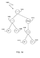
- FIG. 14 is a feature tree representation 1400 of the feature chains that produce the shelled part 1300 in FIG. 13 .
- the feature chain defining the original body F1 is depicted by nodes 1402, 1404, and 1406, which represent a subtraction operation, a block, and a cut, respectively.
- An identical feature chain F2 is depicted by nodes 1408, 1410, and 1412.
- the feature chain defining the offset body O1 is represented by node 1414 (i.e., the offset operation) and the nodes subordinate to node 1414.
- node 1416 forms feature chain F3 by subtracting the offset body from the original body. Note that in the current configuration, F1 and F2 are identical and thus can be optimized to avoid redundant processing.
- shells are constructed by two distinct operations, namely, an offset operation and a subtraction operation.
- the set of features used as input to these operations can differ.
- the set of features used as input to the offset operation is referred to as the "shell definition.”
- the set of features used as input to the subtraction operation is referred to as the "shell scope.”
- the shell definition and shell scope are identical. However, this need not be the case.
- bosses B1 and B2 are united.
- a number of different shells can be created using bosses B1 and B2, depending on the shell definition and shell scope.
- the shell definition and shell scope can be comprised of both B1 and B2.
- the shell definition can be limited to B1 only while the shell scope remains both B1 and B2.
- Other possible results arise using various combinations of B1 and/or B2 for the shell definition and shell scope including, by way of non-limiting example, when both the definition and scope are limited to B1.
- model management technology described herein saves a design engineer a considerable amount of time and effort while designing an assembly consisting of parts.
- the present invention provides substantial automation where a great deal of manual intervention was previously necessary.
- a design engineer who is not in the habit of contemplating feature order e.g., an engineer trained to design in 2D
- a design engineer accustomed to working in 3D no longer needs to contemplate how features should be ordered prior to beginning to construct a part using a 3D CAD system.
- the order in which features are created is no longer an issue with the present invention.
- the invention may be implemented in digital electronic circuitry, or in computer hardware, firmware, software, or in combinations thereof.
- Apparatus of the invention may be implemented in a computer program product tangibly embodied in a machine-readable storage device for execution by a programmable processor; and method steps of the invention may be performed by a programmable processor executing a program of instructions to perform functions of the invention by operating on input data and generating output.
- the invention may advantageously be implemented in one or more computer programs that are executable on a programmable system including at least one programmable processor coupled to receive data and instructions from, and to transmit data and instructions to, a data storage system, at least one input device, and at least one output device.
- Each computer program may be implemented in a high-level procedural or object-oriented programming language, or in assembly or machine language if desired; and in any case, the language may be a compiled or interpreted language.
- Suitable processors include, by way of non-limiting example, both general and special purpose microprocessors. Generally, a processor will receive instructions and data from a read-only memory and/or a random access memory.
- Storage devices suitable for tangibly embodying computer program instructions and data include all forms of non-volatile memory, including by way of example semiconductor memory devices, such as EPROM, EEPROM, and flash memory devices; magnetic disks such as internal hard disks and removable disks; magneto-optical disks; and CD-ROM disks. Any of the foregoing may be supplemented by, or incorporated in, custom-designed ASICs (application-specific integrated circuits).
- Implementations may change the order in which operations are performed. Depending on the needs of an implementation, particular operations described herein may be implemented as a combined operation, eliminated, added to, or otherwise rearranged. Accordingly, other embodiments are within the scope of the following claims.
Landscapes
- Physics & Mathematics (AREA)
- Geometry (AREA)
- Engineering & Computer Science (AREA)
- Computer Graphics (AREA)
- Software Systems (AREA)
- General Physics & Mathematics (AREA)
- Theoretical Computer Science (AREA)
- Processing Or Creating Images (AREA)
- Image Generation (AREA)
Description
- Computer-aided design (CAD) software allows a user to construct and manipulate complex three-dimensional (3D) models of assembly designs. A number of different modeling techniques can be used to create a model of an assembly. These techniques include solid modeling, wire-frame modeling, and surface modeling. Solid modeling techniques provide for topological 3D models, where the 3D model is a collection of interconnected edges and faces, for example. Geometrically, a 3D solid model is a collection of trimmed surfaces. The trimmed surfaces correspond to the topological faces bounded by the edges. Wire-frame modeling techniques, on the other hand, can be used to represent a model as a collection of simple 3D lines, whereas surface modeling can be used to represent a model as a collection of exterior surfaces. CAD systems may combine these, and other, modeling techniques, such as parametric modeling techniques.
- Parametric modeling techniques can be used to define various parameters for different features and components of a model, and to define relationships between those features and components based on relationships between the various parameters. Solid modeling and parametric modeling can be combined in CAD systems supporting parametric solid modeling.
- A design engineer is a typical user of a 3D CAD system. The design engineer designs physical and aesthetic aspects of 3D models, and is skilled in 3D modeling techniques. The design engineer creates parts and may assemble the parts into one or more subassemblies. In addition to parts, a subassembly may also consist of other subassemblies. Using parts and subassemblies, the design engineer designs an assembly. Hereinafter, parts and subassemblies are collectively referred to as components.
- A part is constructed using various geometric building blocks. Geometric building blocks, hereinafter referred to as features, may be constructed by first creating a two-dimensional profile and extruding that profile into a three-dimensional object. Features may be divided into two primary categories. The two primary categories are features used to add material to a part, such as a boss, and features used to subtract material from a part, such as a cut.
- The order in which a design engineer creates features while constructing a part affects the physical structure of that part in a feature-based CAD system. For example, a part constructed first by cutting a block with a cylinder and then adding a boss that extends inside the void left by the cut cylinder will result in a hole with material from the boss inside the hole. If the order of the operations were reversed such that the boss was added before the cylindrical cut, then the cut would not only cut the material of the original block, but also that of the subsequent boss, resulting in a hole with no material inside of it.
- Generally, in a feature-based CAD system, a feature acts on all features that have been previously included in the model and has no effect on features subsequently introduced to the model. Thus, feature-based modeling systems are also history-based modeling system. The design engineer is required to control the scope of a feature by manipulating the feature's location in the overall historical order of features. Commercially available feature-based modeling systems include the SolidWorks® 2001 Plus software system available from SolidWorks Corporation of Concord, Massachusetts.
- History-based CAD systems that define components as a sequence of simple feature operations work on the same principal. The data (e.g., points, lines, and dimensions) necessary to regenerate a component is stored as one or more features and the component keeps an ordered list of these features. Each feature has a corresponding regeneration algorithm that takes the feature data and the geometry resulting from the previous features in the ordered list and modifies the geometry according to the feature's definition (e.g., make a cut of a certain shape at a certain location). To create a new component, the user typically will add features one by one to the component's feature list. To modify a feature, the user simply changes the feature's data and then the system recreates the component by deleting the old resulting geometry and regenerating each feature one by one in the order in which the user originally specified the features. Thus, in the current state of the art, the user's feature creation order is identical to the internal feature regeneration order.
- While building a part, the order in which a design engineer should introduce features and direct the system to perform operations is not always intuitive. Many times the design engineer has invested a great deal of time designing a part before discovering that the features should be introduced in a different order. When the design engineer realizes that the feature ordering did not achieve the desired result (e.g., the desired geometric result), he or she must modify the definition of the part, for example, by rearranging the hierarchical structure of the part.
- One way in which the definition of a part may be modified is to redesign the features that define the part. Those features that were introduced in an order that caused the geometry to be generated incorrectly may need to be deleted and re-created in an order that causes the geometry to be generated correctly. Thus, the design engineer must spend additional time defining the same feature again.
- Another way in which the definition of a part may be modified is to change the feature history. A CAD system may keep track of the feature history and present the history to the design engineer as a hierarchical collection of features. The feature history may be presented in a window (or a section of the window) generated by the CAD system. The design engineer may be able to rearrange the collection of features by dragging a depiction of a feature to a different position in the hierarchical collection, and thereby modify the feature history for a part.
U.S. Patent No. 5,815,154 to Hirschtick et al discloses a system for modifying a model by allowing a user to graphically manipulate a hierarchical collection of features. - Some design engineers may decide that re-designing the part is too time-consuming. A design engineer may find that the incorrect geometry can be easily corrected by adding a cut that is identical to another cut. Although the identical cut is redundant, the geometry is corrected quickly without re-ordering the features in a part.
- Due to the problem of introducing features in a particular order, modeling a part may require a great deal of planning and expertise. The design engineer must determine the correct ordering of features before creating the features to obtain the desired geometric result. The ordering problem is present throughout the modeling process. The difficulty of the ordering problem may increase as the modeling process progresses because as a part becomes more complex, the design engineer has more difficulty determining the correct feature order. Although, a CAD system may provide a feature management tool to help a design engineer rearrange the history of features included in a part, the design engineer is encumbered with analyzing the feature history and re-ordering the features in the part hierarchy as necessary to ensure that the part is geometrically correct.
- A design engineer who intends to become skilled in 3D feature-based modeling needs to become proficient in ordering features. Learning how best to introduce features is part of the experience necessary for becoming skilled in the art of 3D feature-based modeling.
- Additionally, features may be dependent on other features. For example, the position of one hole may depend on the position of a second hole. This type of geometric dependency may be defined by establishing a parametric relationship between the two holes. When the value of an attribute of one feature in the parametric relationship is modified, the value of an attribute of another feature in the parametric relationship may be automatically modified in response. Generally, a design engineer intends that a parametric relationship be preserved when re-ordering the hierarchical structure of a part. The burden is placed on the design engineer first to be aware of the dependencies and second to ensure that they are preserved (perhaps by re-establishing the dependencies if the dependencies are severed during a re-ordering process).
- Often the design engineer discovers that the feature order results in the creation of a physically incorrect part. Therefore, a burden is placed on the design engineer to recreate portions of the part or the entire part, re-order the features that constitute the part, or in some other tedious manner, correct the inaccurate geometry. The design engineer spends an enormous amount of time and effort during the 3D modeling process controlling the feature order and the feature order's effect on the final geometric representation of a part.
- Publication from SU C-J et al: "An integrated form-feature-based Design System for Manufacturing", Journal of Intelligent Manufacturing, vol 6, no 5, Oct 1995, discloses a form-feature-based modeling system and addresses the important issue of utilizing feature information for manufacturing. This document presents a machinability-checking module which analyse a feature's machinability on a three-axis machining center. This document is concerned with feature interactions resolution for manufacturing the object that was modeled and deals with interfering features depending on their order of creation.
- Publication from Sormaz D N et al: "Modeling of Manufacturing Feature Interactions for Automated Process Planning", Journal of Manufacturing Systems, no 1, 2000, analyses manufacturing feature interactions and presents algorithms for handling feature interactions in manufacturing process planning. This document is concerned with feature interactions resolution for manufacturing the object that was modeled, with respect to tolerance relationship between two features and forces of the machining process. This document deals with interfering features while machining the object, once the object model was created.
- Document
US-A-6 256 596 discloses a flexible framework within a CAD application program. This document relates to handling feature information in a parametric feature-based solid modeler, and in particular, to a method for providing an extensible framework for capturing feature information in a neutral format. This document is however not concerned with the modeling of a three-dimensional object but is concerned with improving the techniques to access CAD designed part data. - Users of computer-aided design systems do not need to concern themselves with the order in which features are defined for a model when feature creation order and feature generation order are independent of one another. To facilitate the independence of feature creation order and feature regeneration order, systems and methods may be provided to determine the scope of a feature.
- Systems and methods for defining a scope of a feature are disclosed herein. These systems and methods include storing data that defines features of a computer model and forming a feature chain with at least one feature object. The feature object has a design effect limited in scope such that an operation for removing material operates to affect another feature object in the same feature chain and does not affect feature objects in another feature chain. Feature chains are combined and form an interrelationship among feature objects that represents a hierarchy, which defines the construction of the model from the feature objects. In one aspect, an unordered feature list comprising the plurality of feature objects is read, at least one feature object that adds material to the computer model is located, and at least one feature object that removes material from the computer model and is associated by a scope definition with the feature object that adds material is located. A feature object that removes material can have a never-fill attribute to indicate a cutting effect on each feature object that adds material.
- Further aspects include optimizing the feature chains and inputting the combination of the feature chains, which prescribes the regeneration order, into a process that generates a part. Moreover, the scope definition can be based on feature object existence, on feature object proximity, or on a combination of feature object existence and feature object proximity. Implementations can enable the user to issue an instruction to modify the scope definition, whereby the instruction explicitly specifies either a feature object to include in the scope definition or a feature object to exclude from the scope definition. Additionally, a user interface dialog can facilitate the explicit specification of the scope definition.
- The details of one or more embodiments of the invention are set forth in the accompanying drawings and the description that follows. Other features, objects, and advantages of the invention will be apparent from the description and drawings, and from the claims.
-
-
FIG. 1 is a diagram of a computer system. -
FIG. 2 is an illustration of a model displayed in a window. -
FIG. 3 is an illustration of three views of a part. -
FIG. 4 is an illustration of three views of a part. -
FIG. 5 is an illustration of three views of a part. -
FIG. 6a is an illustration of a part consisting of five bosses and one cut. -
FIG. 6b is an illustration. of a part consisting of five bosses and one cut. -
FIG. 7 is a flowchart of a procedure performed by the feature chain generator. -
FIG. 8 is an illustration of data and procedures. -
FIG. 9 is an illustration of a feature tree. -
FIG. 10 is an illustration of a feature tree. -
FIG. 11 is an illustration of three views of a part. -
FIG. 12 is an illustration of a feature tree. -
FIG. 13 is an illustration of three views of a part. -
FIG. 14 is an illustration of a feature tree. - The present invention allows design engineers to design components without worrying about feature order. This is achieved by separating the concepts of feature creation order and feature regeneration order. Therefore, the order in which a user adds features to a component is independent of the order in which the geometric feature operations (e.g., applying a boss or applying a cut) are applied to the underlying geometric model. The present invention provides a mechanism that automatically determines feature regeneration order independent of the user's feature creation order. Such an automated mechanism saves the design engineer an enormous amount of time and effort during the 3D modeling process because he or she is freed from redesigning parts and/or manipulating the order of features to correct geometry. Unlike conventional feature-based modeling systems wherein the feature regeneration order is defined and controlled solely by the user, the present invention controls the regeneration order, which not only takes a large burden off the user, but also adds beneficial dynamic qualities overall to a feature-based modeling system.
- The present invention enables design engineers to construct featured-based models without excessive consideration to the order in which the features are defined. Rather than requiring a design engineer to rely on feature order to control the final geometric representation of a part, the present invention builds data structures that group features and automatically modifies the groupings as needed. The groupings may be modified when the design engineer indicates the scope upon which a feature should act (i.e., explicit scope), when certain attributes of the feature indicate an implicit scope, or when a combination of explicit and implicit scope so indicates. By providing an automated process for ordering and grouping the features that contribute to the definition of a part, the present invention gives the design engineer additional controls over the final shape of a part, and enhances the flexibility and functionality of a computerized modeling system.
-
FIG. 1 shows acomputerized modeling system 100 that includes aCPU 102, aCRT 104, akeyboard input device 106, amouse input device 108, and astorage device 110. TheCPU 102,CRT 104,keyboard 106,mouse 108, andstorage device 110 can include commonly available computer hardware devices. For example, theCPU 102 can include a Pentium-based processor. Themouse 108 may have conventional left and right buttons that the user may press to issue a command to a software program being executed by theCPU 102. Other appropriate computer hardware platforms are suitable as will become apparent from the discussion that follows. Such computer hardware platforms are preferably capable of operating the Microsoft Windows NT, Windows 95, Windows 98, Windows 2000, Windows XP, Windows ME, or UNIX operating systems. - Computer-aided design software is stored on the
storage device 110 and is loaded into and executed by theCPU 102. The software allows the design engineer to create and modify a 3D model and implements aspects of the invention described herein. TheCPU 102 uses theCRT 104 to display a 3D model and other aspects thereof as described later in more detail. Using thekeyboard 106 and themouse 108, a design engineer can enter and modify data associated with the 3D model. TheCPU 102 accepts and processes input from thekeyboard 106 andmouse 108. TheCPU 102 processes the input along with the data associated with the 3D model and makes corresponding and appropriate changes to that which is displayed on theCRT 104 as commanded by the modeling software. Additional computer processing units and hardware devices (e.g., video and printer devices) may be included in thecomputerized modeling system 100. Furthermore, thecomputerized modeling system 100 may include network hardware and software thereby enabling communication to ahardware platform 112. Those of ordinary skill in the art will appreciate that the invention could also be used in conjunction with other computer-aided design software that addresses applications other than mechanical design. - A computer-aided modeling system may have the capability of retaining a design engineer's original design intent as a model undergoes modifications before the model design is complete. A parametric modeling system (or a parametric solid modeling system), ensures that certain aspects of the design engineer's intent are retained. In one embodiment, the underlying data structures of the modeling software behave parametrically. For example, the geometry, display attributes, and annotations displayed as part of the model on the
CRT 104 are updated as needed when a design engineer changes the model. Those of ordinary skill in the art will appreciate how to design a parametric modeling system. - In one embodiment, the modeling system is a solid modeling system. The model may be an assembly of solid model components or simply a part. The solid model may have relationships that parametrically constrain the definitions of one or more components or features with respect to one another. If a parametrically constrained relationship exists between two features, a geometric modification to one feature may cause a geometric modification in the other feature. The present invention may preserve parametric relationships in the reorganized part structure by using computational resources to analyze the dependencies when ordering features and ensuring that the dependencies are maintained.
-
FIG. 2 shows awindow 202 displayed on theCRT 104 and generated by a CAD software system. Thewindow 202 is a conventional computer-generated window that can be programmed by one of ordinary skill in the art using conventional, commercially available, software programming tools, such as those available from Microsoft Corporation of Redmond, Washington. - A computer-generated
3D model 204 is displayed within amodeling portion 206 of thewindow 202. The design engineer can construct and modify the3D model 204 in a conventional manner. The surfaces of the3D model 204 can be displayed, or the3D model 204 can be displayed using solid lines and dashed lines to show visible edges and hidden edges, respectively, of the 3D model. Implementations also may include other window areas, such as an order independent list of features 208, which helps the design engineer visualize and manipulate themodel 204 shown in themodeling portion 206. -
FIG. 3 shows awindow 302 that contains three views of a part under construction. The top view 304,front view 306, and rotatedview 308 reveal that the part is partially defined by two block features (i.e., upper block 312 and lower block 314). Additionally, the top view 304 and thefront view 306 plainly show anextruded profile 310 of a circle. The purpose of the extrudedprofile 310 is to create a cylindrical cut feature in the part. -
FIG. 4 shows thewindow 302 after the extrudedprofile 310 was used to construct acut feature 402. Thecut 402 was created by subtracting material that was located within the extrudedprofile 310 from the upper block 312 and the lower block 314. Thecut 402 would appear as illustrated inFIG. 4 in a CAD system that is based on feature existence if the upper block 312 and the lower block 314 were included in the part definition (i.e., existed) prior to the inclusion ofcut feature 402. -
FIG. 5 shows thewindow 302 containing a part in which acut feature 502 did not subtract material from the upper block 312. Thecut 502 may appear as illustrated inFIG. 5 in a CAD system that is based on feature existence if the lower block 314 was included in the part definition first, thecut feature 502 was included in the part definition second, and the upper block 312 was included in the part definition third. Therefore, the scope of thecut 502 is the lower block 314 only. - Rather than being solely dependent on the prior existence of features, the present invention allows a design engineer to explicitly specify one or more features on which a particular feature acts. This enables the design engineer to include a feature in or exclude a feature from the scope of a particular feature. Hereinafter, the collection of features on which another feature acts is referred to as "feature scope." A feature has explicit feature scope if that feature removes material from another feature as instructed by a design engineer. For example, the present invention enables the design engineer to include the upper block 312 and the lower block 314 in the part definition prior to introducing the
cut feature 502, then indicate that the feature scope of thecut feature 502 is lower block 314 only, thereby constructing the part shown inFIG. 5 . - While a part is being designed, the design engineer may discover that the part is physically incorrect due to the order in which features were introduced during the design process. Unlike conventional, history-based modeling systems, the present invention enables the design engineer to specify the explicit scope of a feature. A user interface command may facilitate the specification of explicit scope of a feature, as will be discussed.
- A feature may also have implicit feature scope. One example of implicit feature scope is when a feature removes material from an existing feature without being instructed to do so by the design engineer. This may occur due to the order in which a feature was introduced to a part and/or due to a proximity calculation wherein the physical extent of a feature determines the implicit feature scope. Another example of implicit feature scope is when a first feature removes or does not remove material from a second feature based on an attribute of the first or second feature. Such implicit scope results, by way of non-limiting example, when a cut is defined with a "never-fill" attribute that prevents any feature that adds material to fill the cut with material. Additionally, a boss (i.e., any feature that adds material) may be defined with a "never-cut" attribute that prevents the boss from being included in any cut's feature scope, meaning that the boss will not be affected by any cut.
- Features may also have a combination of implicit and explicit scope. As an example, a "never-fill" attribute may be overridden by certain actions. Such an action may occur when a user specifically instructs the modeling system to override the "never-fill" attribute for a particular feature or a collection of features (e.g., a pocket feature constructed from more than one feature).
- Implicit and explicit feature scopes are not mutually exclusive. That is, although the system may implicitly determine a feature's scope, the design engineer would subsequently be able to explicitly modify the system-determined feature scope and even redefine the feature scope entirely.
- Referring once again to
FIG. 4 , assume that when the design engineer built the part illustrated inFIG. 4 , he or she defined thecut 402 first, followed by the upper block 312, and then lower block 314. In this case, upper block 312 and lower block 314 may be included explicitly in the feature scope ofcut 402 if the design engineer instructs the system to apply thecut 402 to the upper block 312 and the lower block 314. One way in which a design engineer may specify explicit feature scope is for the CAD system to provide a user interface command that enables the design engineer to select thecut 402 then select the block or blocks on which thecut 402 should act. - In one embodiment, the user interface contains a command for specifying the explicit scope of a feature. After selecting the command, the design engineer may first select one feature that removes material from the part, then may select one or more features that add material to the part, then indicate that the selection is complete. Alternatively, the design engineer may first select one or more features that add material to the part, then may select one feature that removes material from the part, then indicate that the selection is complete. The present invention analyzes the selected features and determines whether a feature that removes material was selected first or whether one or more features that add material were selected first. When a feature that removes material is selected prior to the selection of features that add material, the selected features that add material are automatically added to the feature scope of the selected feature that removes material from the part. When one or more features that add material are selected prior to a feature that removes material, the features that add material to the part are automatically excluded from the feature scope of the feature that removes material from the part. Thus, the behavior of the user interface command depends on which type of feature was selected first.
- The user interface in an embodiment may also display a dialog box to facilitate the specification of feature scope. The dialog box may list features belonging to the feature scope of a particular feature and allow the design engineer to add or remove features from the feature scope list. The CAD system may provide graphical feedback by highlighting, in the modeling portion of a window, those features belonging to the feature scope. The design engineer may also be allowed to pick features in the modeling portion of the window to add and remove from the feature scope, such that an associative relationship exists between the features as listed in the dialog box and as displayed in the modeling portion of the window.
- Continuing to refer to
FIG. 4 , assume that when the design engineer built the part illustrated inFIG. 4 , he or she randomly defined the lower block 314 first, followed by the upper block 312, and then thecut 402. In one embodiment, the feature scope of thecut 402 is the upper block 312 and the lower block 314. This scope may be determined implicitly based on the features that exist at the time of feature creation, that is, block 312 and block 314 may be included implicitly in the feature scope ofcut 402 becausecut 402 was included in the part after the inclusion of upper block 312 and lower block 314. A boss added subsequently, however, would not be included implicitly in the scope ofcut 402. - Implicit feature scope may also be determined by proximity in combination with prior existence of a feature. When implicit scope is determined by proximity, the feature scope of a feature that removes material includes any feature that adds material and that volumetrically interferes with the feature that removes material. Another pre-existing feature that adds material that is outside the volume of the cutting area is excluded from the feature scope of the feature that removes material. A combination of prior existence of a feature and geometry proximity as well as other feature-feature relationships can be used to determine implicit feature scopes.
- Referring now to
FIG. 6a , apart 600 consisting of five bosses (602-610) and acylindrical cut 612 is shown. In an embodiment that determines implicit scope based on the proximity of features in addition to feature existence, the feature scope of thecylindrical cut 612 is all bosses that existed prior to the definition of thecylindrical cut 612 and volumetrically interferes with thecylindrical cut 612. Assuming for this illustration that bosses 602-610 existed prior tocylindrical cut 612, the feature scope ofcylindrical cut 612 isboss 606 andboss 608 becauseboss 606 andboss 608 are within the extent of thecylindrical cut 612. - Referring now to
FIG. 6b , thepart 600 is modified such thatboss 610 is positioned betweenboss 606 andboss 608. When the part is modified to reposition theboss 610, the feature scope of thecylindrical cut 612 is not modified. The feature scope ofcylindrical cut 612 is not modified because in this embodiment the proximity and pre-existence criteria for determining feature scope are applied at the time of feature creation (and not at subsequent re-generations of the part) and serve as a basis for the feature scope. After feature creation, the feature scope is under the design engineer's control. However, ifcylindrical cut 612 had a "never-fill" attribute,boss 610 would be included in the feature scope ofcylindrical cut 612 after being moved. - An aspect of the present invention dynamically groups and orders features, and determines how groupings of features should be combined. The groupings and the order of features in each grouping are determined by feature scope. A grouping of features is hereinafter referred to as a "feature chain."
- In one embodiment, features belonging to the same feature chain may be combined using Boolean operations. Additionally, one or more feature chains may then be combined to produce the final shape of a part. One feature chain may always exist to consolidate all other feature chains.
- A feature chain maintains three volumes. The first volume is a positive volume that combines all features that add material. The second volume is a negative volume that combines all features that remove material. The third volume combines the positive and negative volumes.
- There are two types of feature chains, simple feature chains and composite feature chains. Simple feature chains always have one feature that adds material and zero or more features that remove material. A composite feature chain can have one or more features or feature chains that add material, and one or more features or feature chains that remove material.
- A feature chain generator builds simple feature chains whenever a feature is added, a feature is removed, a feature scope is modified, or a shell definition is modified. Composite feature chains are formed from simple feature chains and then may be input to an optimization process.
- Either simple feature chains or optimized composite feature chains are used as input to a rebuild engine, which constructs the part. The feature chains specify the feature order to the rebuild engine, opposed to conventional history-based modeling systems where the user was solely responsible for specifying order.
- Referring now to
FIG. 7 , a flowchart of aprocedure 700 performed by the feature chain generator in an embodiment is shown. Theprocedure 700 reads anunordered feature list 702. The unordered feature list is created when the design engineer first defines a feature and is updated as additional features are defined and when features are deleted. As the unordered feature list is read, theprocedure 700 determines if a feature adds material to apart 704. If the feature adds material to the part, a simple feature chain is created and the feature is included as the positive volume (and the first feature) in thesimple feature chain 706. - When the
procedure 700 has finished locating all features that add material, theprocedure 700 locates all features that remove material. Thus, theprocedure 700 may read the unordered feature list again 708. Theprocedure 700 determines if a feature removesmaterial 710, and if so, determines the feature scope of that feature. Data in the form of feature scope and never-fill indicators is associated with all features that remove material to aid in the determination. Theprocedure 700 determines if the feature is a cut having a "never-fill"attribute 712, and if the feature is, the feature is included in eachsimple feature chain 714. (Alternatively, in another embodiment, the "never-fill" cut is added to the composite feature chain only.) If the feature is a feature that removes material but is not a cut having a "never-fill" attribute, then the feature scope for that feature is examined. The feature is then included as the negative volume in all simple feature chains having as the positive volume the features in thefeature scope 716. - When the
procedure 700 has located all features that remove material, a composite feature chain is created to combine allfeature chains 718. A Boolean union operation may be performed to combine all feature chains. After the feature chains are combined,procedure 700 completes. - Referring now to
FIG. 8 , an illustration of data and procedures that may be used in an implementation of the present invention is shown. To generate a feature chain, data in the form of anunordered feature list 802, and for those features that remove material, data in the form of feature scope / never-fill indicators 804 is input to thefeature chain generator 806. Thefeature chain generator 806 groups and orders features from theunordered feature list 802 in view of the feature scope / never-fill indicators 804, as previously discussed. The output from the feature chain generator is transientfeature chain data 808. - Optionally, the transient
feature chain data 808 may be used as input to anoptimizer 810. (Otherwise, the transientfeature chain data 808 is directly input to therebuild engine 814.) The function of theoptimizer 810 is to reduce the size of the feature chain and allow for more efficient processing of the feature chain data. Reducing the size of the feature chain allows for more efficient processing because the number of times a feature needs to be processed is decreased. - Optimized transient
feature chain data 812 is output from theoptimizer 810 and used as input to arebuild engine 814. Therebuild engine 814 rebuilds the features individually based on the design engineer's input parameters and construction geometry that are stored with the data that defines the features. The present invention may use a rebuild engine such as that described inU.S. Patent No. 5,815,154 to Hirschtick et al. - The output of the
rebuild engine 814 is apart 816. The part may consist of geometry (e.g., vertices, edges, faces, and surfaces), and/or may consist of solid bodies in the case where solid features such as extrusions and fillets were used to define the part. Additionally, a feature may be a two-dimensional feature. - One advantage of the use of feature chains is that the feature chains may be rebuilt by separate threads or processors in a multi-processor computerized modeling system. Therefore, the performance of the present invention may increase in scale with the number of processors available in the computerized modeling system.
- Referring back to
FIG. 4 , an example of a feature chain generated for the part shown inFIG. 4 will now be discussed. A simple feature chain is built beginning with a feature that adds material followed by all features that remove material from the feature that adds material. For example, the upper block 312 and lower block 314 shown inFIG. 4 add material, whereas thecut 402 removes material. Therefore, a first simple feature chain F1 beginning with upper block 312 and a second simple feature chain F2 beginning with lower block 314 is built, and both of these feature chains includecut 402. Additionally, a composite feature chain F3 would be constructed for the purpose of combining the first two feature chains. The feature chains that generate the part shown inFIG. 4 may be represented as follows: - F1 = Upper Block 312 | Cut 402
- F2 = Lower Block 314 | Cut 402
- F3 = F1, F2
- In the feature chain equations herein, the positive volumes of a feature chain are to the right of the equal sign and to the left of the " | " character, and the negative volumes of a feature chain are to the right of the "|" character. The "|" character denotes the combination of the positive and negative volumes in the feature chain. The third volume is denoted by the characters on the left side of the equation. Some equations use shorthand by leaving out the characters "| Ø" when the feature chain has no negative volume.
- The chains may be optimized to reduce the size of the part definition and to increase the efficiency of computing resources. Consolidating all feature chains having identical features that remove material is one way feature chains may be optimized. Thus, in the preceding representation, feature chains F1, F2 and F3 may be combined as follows:
- F4 = Upper Block 312, Lower Block 314 | Cut 402
- Referring now to
FIG. 9 , a tree-like visual representation (referred to as a feature tree 900), of the feature chain F4 is shown. Theunion operator 902 combines the upper block 312 and the lower block 314 (depicted bynodes subtraction operator 904 subtracts the cut 402 (depicted by node 910), from the union of the upper block 312 and the lower block 314. As shown in thetree 900, theoperation 904 is a parent operation tochild operations operation 902 is a parent operation tochild operations - In one implementation, feature chains may also be considered features and used in other chains. A chain that only contains one feature (or one chain) is optimized by adding the feature to the final chain. For example, if a side block were added to the part in the foregoing example, an un-optimized feature chain F5 with one feature that is the side block and an optimized final feature chain F6 may be represented as follows:
- F5 = side block | Ø
- F6 = side block, F4
- Referring once again to
FIG. 5 , the part illustrated inFIG. 5 contains acut feature 502. Possibly, the design engineer defined lower block 314 first, followed bycut 502, and then upper block 312. If implicit scope is determined by feature existence, in this case, thecut 502 has implicit scope to act only upon lower block 314 becausecut 502 was defined after lower block 314 and before upper block 312. The feature chains that represent the part illustrated inFIG. 5 may be represented as follows: - F1 = Lower Block 314 | Cut 502
- F2 = Upper Block 312 | Ø
- F3 = F1, F2
- Referring now to
FIG. 10 , afeature tree 1000 that represents the feature chain for the part illustrated inFIG. 5 is shown. InFIG. 10 , thesubtraction operator 1004 has the effect of removing the material defined by the cut 502 (depicted as node 1008) from lower block 314 (depicted as node 1006). Theunion operator 1002 combines the result of the subtraction operation with the upper block 312 (depicted as node 1010). - The part illustrated in
FIG. 5 would appear as the part illustrated inFIG. 4 if the feature scope is not ultimately determined by the pre-existence of features. For example, a different implicit scope may be associated withcut 502 if a "never-fill" attribute was specified for thecut 502 when thecut 502 was created, resulting in an implicit scope such that every feature that adds material is affected by thecut 502 in such a way that thecut 502 could never be filled by any feature that adds material. (A "never-fill" attribute may be specified for thecut 502 after the creation of thecut 502 and after the subsequent creation of other features, in which case, the "never-fill" attribute may result in an explicit scope specification.) Cuts having a "never-fill" attribute are added to the negative volume in the final feature chain. The part illustrated inFIG. 5 would also appear as the part illustrated inFIG. 4 if an explicit scope is specified after all the features were defined by, for example, using a feature scope command provided in the user interface, as was previously discussed. Feature chains are automatically re-created to re-group and re-order features as necessary when explicit feature scope is specified. - Referring now to
FIG 11 , thewindow 302 containing three views of apart 1100 is shown. The part was created by shelling a block feature (meaning that the block feature was hollowed), then applying acylindrical cut 1102 to the hollowed block feature. When a feature is shelled, the design engineer may specify a face to be removed, in addition to the thickness of the wall of the shell. InFIG. 11 , a rectangular face is removed to reveal the inside of thepart 1100. - There are two different kinds of shell operations, which are an inward shell operation and an outward shell operation. An inward shell operation offsets the original faces of a solid in an inward direction and constructs new shell faces on the inside of the part. An outward shell operation offsets the original faces in an outward direction, leaving the inverted original faces on the inside of the part and constructing new shell faces on the outside of the part. An outward shell operation grows the part in overall size, whereas the part remains the same overall size after the inward shell operation completes. The inward shell operation is a two-part operation. First, the faces of the features that define the shell are offset inward in a standard offset operation. The result of the offset operation is a solid that is then subtracted from the original solid leaving the final shelled result. A procedure to create an outward shell is also comprised of two distinct operations. The first operation offsets the original body outward. The second operation subtracts the original body from the offset body. Parts may have multiple shelling features that affect various subsets of features within a part.
- To generate the feature chains for the part shown in
FIG. 11 , a first chain F1 consisting of only a block is created. Next, the block feature that defines the shell forms feature chain F2. (If one or more features in addition to the block were to define the shell, all those features would be grouped together to form the feature chain F2.) An inward offset operation is applied to the result of F2 to form O1 (i.e., the offset body). Next, the offset O1 is subtracted from F1 resulting in F3. Finally, the cylindrical cut is subtracted from F3 to form the feature chain F4. - F1 = block | Ø
- F2 = block | Ø
- O1 = offset F2
- F3 = F1 | O1
- F4 = F3 | cylindrical cut
-
FIG. 12 is afeature tree representation 1200 of the preceding feature chains.Node 1204 andnode 1208 represent the block, which is identical, in F1 and F2.Node 1206 represents the offset operation, and together withnode 1208 depicts the feature chain O1.Node 1202 represents a subtraction operation and forms the feature chain F3 by subtracting the offset block from the block (which will cause the creation of the shelled block).Node 1212 represents a subtraction operation and forms the feature chain F4 by subtracting the cylindrical cut represented bynode 1210 from the shelled block. - Referring now to
FIG. 13 , thewindow 302 containing three views of apart 1300 is shown.FIG. 13 differs fromFIG. 11 because acylindrical cut 1302 is included in the definition of the shell (i.e., thecylindrical cut 1302 is included in the offset operation). The result being that thecylindrical cut 1302 is shelled instead of the shell being cut by a cylinder as shown inFIG. 11 . The feature chains that represent thepart 1300 shown inFIG. 13 maybe represented as follows: - F1 = block | cylinder cut
- F2 = block | cylinder cut
- O1 = offset F2
- F3 = F1 | O1
-
FIG. 14 is afeature tree representation 1400 of the feature chains that produce the shelledpart 1300 inFIG. 13 . The feature chain defining the original body F1 is depicted bynodes nodes node 1414. Finally,node 1416 forms feature chain F3 by subtracting the offset body from the original body. Note that in the current configuration, F1 and F2 are identical and thus can be optimized to avoid redundant processing. - As discussed, shells are constructed by two distinct operations, namely, an offset operation and a subtraction operation. The set of features used as input to these operations can differ. The set of features used as input to the offset operation is referred to as the "shell definition." The set of features used as input to the subtraction operation is referred to as the "shell scope." In the example described with reference to
FIG. 11 andFIG. 12 , and the example described with reference toFIG. 13 andFIG. 14 , the shell definition and shell scope are identical. However, this need not be the case. - Consider the example where two bosses B1 and B2 are united. A number of different shells can be created using bosses B1 and B2, depending on the shell definition and shell scope. For example, the shell definition and shell scope can be comprised of both B1 and B2. Alternatively, the shell definition can be limited to B1 only while the shell scope remains both B1 and B2. Other possible results arise using various combinations of B1 and/or B2 for the shell definition and shell scope including, by way of non-limiting example, when both the definition and scope are limited to B1.
- This flexibility in the way in which feature scope can be defined allows for designs to be created that are otherwise quite complex to create in a conventional history-based modeler. For example, local shelling (i.e., some portions of a part are shelled and not others) is quite straight forward using the present invention because the shell definition can simply be limited to the features that are to be hollowed. However, in a conventional history-based modeling approach, local shelling is very difficult because the design engineer needs to plan the feature order and the precise feature groupings necessary to create a local shell in advance.
- One skilled in the art should appreciate that model management technology described herein saves a design engineer a considerable amount of time and effort while designing an assembly consisting of parts. The present invention provides substantial automation where a great deal of manual intervention was previously necessary. A design engineer who is not in the habit of contemplating feature order (e.g., an engineer trained to design in 2D), does not have to strategize about order when beginning to work with a three-dimensional CAD system. Likewise, a design engineer accustomed to working in 3D no longer needs to contemplate how features should be ordered prior to beginning to construct a part using a 3D CAD system. The order in which features are created is no longer an issue with the present invention.
- The invention may be implemented in digital electronic circuitry, or in computer hardware, firmware, software, or in combinations thereof. Apparatus of the invention may be implemented in a computer program product tangibly embodied in a machine-readable storage device for execution by a programmable processor; and method steps of the invention may be performed by a programmable processor executing a program of instructions to perform functions of the invention by operating on input data and generating output. The invention may advantageously be implemented in one or more computer programs that are executable on a programmable system including at least one programmable processor coupled to receive data and instructions from, and to transmit data and instructions to, a data storage system, at least one input device, and at least one output device. Each computer program may be implemented in a high-level procedural or object-oriented programming language, or in assembly or machine language if desired; and in any case, the language may be a compiled or interpreted language. Suitable processors include, by way of non-limiting example, both general and special purpose microprocessors. Generally, a processor will receive instructions and data from a read-only memory and/or a random access memory. Storage devices suitable for tangibly embodying computer program instructions and data include all forms of non-volatile memory, including by way of example semiconductor memory devices, such as EPROM, EEPROM, and flash memory devices; magnetic disks such as internal hard disks and removable disks; magneto-optical disks; and CD-ROM disks. Any of the foregoing may be supplemented by, or incorporated in, custom-designed ASICs (application-specific integrated circuits).
- A number of embodiments of the present invention have been described. Nevertheless, it will be understood that various modifications may be made without departing from the scope of the invention. For example, implementations that base implicit scope on feature existence and feature proximity may be mutually exclusive. Additionally, the feature chain generator may also build simple feature chains whenever a feature is moved to apply proximity criteria for determining feature scope at subsequent re-generations of the part. Alternatively, a single implementation may give the user a choice whether to base implicit scope on feature order or feature proximity, and allow the user to change that choice while designing a part.
- Implementations may change the order in which operations are performed. Depending on the needs of an implementation, particular operations described herein may be implemented as a combined operation, eliminated, added to, or otherwise rearranged. Accordingly, other embodiments are within the scope of the following claims.
Claims (21)
- A computer-implemented method of modeling a three-dimensional object, comprising:storing data representing a computer model of the three-dimensional object, the data comprising a plurality of feature objects each defining a feature of the computer model,the data further comprising a scope definition of a respective feature of the computer model, wherein the scope definition specifies a collection of features on which the respective feature acts;forming a plurality of groupings of features, wherein the grouping of features is determined by the scope definition of the respective features;modifying the scope definition, wherein modifying the scope definition is performed by including one or more features in or excluding one or more features from the scope definition;wherein each grouping of features comprises a plurality of feature objects and each grouping has a design effect limited in scope such that an operation for removing material operates to affect a plurality of features of the computer model defined by the plurality of feature objects in the respective grouping of features and does not affect ones of the features of the computer model defined by the respective feature object not in said grouping of features; andcombining the groupings of features to form an interrelationship among feature objects that represents a hierarchy defining construction of the model from the feature objects,wherein said hierarchy is independent of the order in which a user creates the plurality of feature objects.
- The computer-implemented method of claim 1 wherein forming the groupings of features comprises:reading an unordered feature list comprising the plurality of feature objects;locating at least one feature object that adds material to the computer model; andlocating at least one feature object that removes material from the computer model and is associated by the scope definition with the feature object that adds material.
- The computer-implemented method of claim 2 wherein at least one feature object that removes material has a never-fill attribute indicating a cutting effect on each feature object that adds material.
- The computer-implemented method of claim 1 further comprising optimizing the combination of groupings of features.
- The computer-implemented method of claim 1 further comprising inputting the combination of the plurality of groupings of features into a process designed to generate a part, the combination prescribing a regeneration order for the plurality of feature objects, said regeneration order being independent of the order of creation of the plurality of feature objects.
- The computer-implemented method of claim 2 wherein the scope definition is based on feature object existence.
- The computer-implemented method of claim 2 wherein the scope definition is based on feature object proximity.
- The computer-implemented method of claim 2 wherein the scope definition is based on a combination of feature object existence and feature object proximity.
- The computer-implemented method of claim 2 wherein an instruction issued by a user modifies the scope definition, the instruction explicitly specifying one of the feature object to include in the scope definition and the feature object to exclude from the scope definition.
- The computer-implemented method of claim 9 wherein a user interface dialog facilitates the explicit specification of the scope definition.
- A readable data storage device comprising instructions for causing a computer to:store a data structure defining a computer model of a real-world three-dimensional object as a hierarchically arranged plurality of model feature objects, the model feature objects being processed by a modeling program to effect generation of the model;receive data from a user to define an additional model feature object;receive data from the user to define a feature scope associated with the additional model
feature object, said feature scope determining at least one other model feature objecton which said additional model feature object acts;modifying the feature scope, wherein modifying the feature scope is performed by including one or more feature objects in or excluding one or more feature objects from the feature scope; andmodify the hierarchical arrangement of the plurality of model feature objects based on the feature scope of the additional model feature object,wherein said hierarchical arrangement is independent of the order in which a user creates the plurality of model feature objects. - The data storage device of claim 11 wherein the hierarchical arrangement is a tree structure and the method further comprises generating the model by parsing the tree structure and determining a scope of operation of each model feature object with respect to other model feature objects based on relative positions of model feature objects in the hierarchical arrangement.
- The data storage device of claim 11 wherein:said feature scope is an explicit feature scope, andthe method further comprises receiving user input explicitly identifying other model feature objects affected by the additional feature object.
- The data storage device of claim 13 wherein receiving user input comprises receiving user-selection of a plurality of model features displayed on a graphical interface device, and processing the user input to identify said other model feature objects affected by the additional model feature object.
- The data storage device of claim 11 wherein:each of the plurality of model feature objects that removes material has an implicit feature scope and whereby the system is configured to determine which of the plurality of model feature objects that removes material affects other ones of the plurality of model feature objects that add material based on the implicit feature scope.
- The data storage device of claim 15 wherein one of the plurality of model feature objects comprises a cut feature and the implicit feature scope of said cut feature sets a never-fill attribute associated with the cut feature.
- The data storage device of claim 16 wherein the never-fill attribute prevents any other model feature object from adding material to the model in a region cut by said cut feature
- The data storage device of claim 16 wherein the never-fill attribute may be overridden by the user such that a specified other model feature object may affect addition of material to the region cut by the cut feature.
- The data storage device of claim 15 wherein:the implicit feature scope of one of the plurality of model feature objects that removes material is determined by the physical proximity of that one of the plurality of model feature objects that removes material to one or more model feature objects that add material.
- The data storage device of claim 15 wherein:the implicit feature scope of one of the plurality of model feature objects that removes material is determined by the existence of other ones of the plurality of model feature objects.
- A digital computer comprising:a memory, data and control information stored in said memory;anda data processor for processing said data in accordance with said control information;wherein, said control information is arranged toprocess a data structure defining a hierarchically arranged plurality of model featureobjects to generate a computer model of a real-world three-dimensional object;receive data from a user to define an additional model feature object;receive data from the user to define a feature scope associated with the additional model
feature object, said feature scope determining at least one other model feature objectson which said additional model feature object acts;modifying the feature scope, wherein modifying the feature scope is performed by including one or more feature objects in or excluding one or more feature objects from the feature scope; andmodify the hierarchical arrangement of the plurality of model feature objects based on the feature scope thereby changing the model of the real-world three-dimensional object,wherein said hierarchical arrangement is independent of the order in which a user creates the plurality of model feature objects.
Applications Claiming Priority (2)
| Application Number | Priority Date | Filing Date | Title |
|---|---|---|---|
| US32949001P | 2001-10-15 | 2001-10-15 | |
| US329490P | 2001-10-15 |
Publications (3)
| Publication Number | Publication Date |
|---|---|
| EP1302904A2 EP1302904A2 (en) | 2003-04-16 |
| EP1302904A3 EP1302904A3 (en) | 2006-02-08 |
| EP1302904B1 true EP1302904B1 (en) | 2013-01-16 |
Family
ID=23285656
Family Applications (1)
| Application Number | Title | Priority Date | Filing Date |
|---|---|---|---|
| EP02292539A Expired - Lifetime EP1302904B1 (en) | 2001-10-15 | 2002-10-15 | Object modeling |
Country Status (3)
| Country | Link |
|---|---|
| US (1) | US7313504B2 (en) |
| EP (1) | EP1302904B1 (en) |
| JP (1) | JP2003162550A (en) |
Families Citing this family (31)
| Publication number | Priority date | Publication date | Assignee | Title |
|---|---|---|---|---|
| US7408560B2 (en) * | 2003-03-05 | 2008-08-05 | Siemens Product Lifecycle Management Software Inc. | System and method for dynamic propagation and display of graphical edits |
| US7086028B1 (en) * | 2003-04-09 | 2006-08-01 | Autodesk, Inc. | Simplified generation of design change information on a drawing in a computer aided design (CAD) environment |
| EP1501026A1 (en) * | 2003-07-25 | 2005-01-26 | Dassault Systèmes | CAD system using a context-free grammar |
| US7398129B2 (en) | 2004-10-07 | 2008-07-08 | Amada Company, Limited | Representation of sheet metal part models |
| JP4472642B2 (en) * | 2005-01-26 | 2010-06-02 | ダッソー システムズ ソリッドワークス コーポレイション | Recognition and active features for computer-aided design systems |
| US8035638B2 (en) * | 2006-03-23 | 2011-10-11 | Autodesk, Inc. | Component suppression in mechanical designs |
| US8504337B2 (en) * | 2007-01-17 | 2013-08-06 | Caterpillar Inc. | Method and system for analyzing three-dimensional linkages |
| US7643027B2 (en) | 2007-01-18 | 2010-01-05 | Dassault Systemes Solidworks Corporation | Implicit feature recognition for a solid modeling system |
| WO2008095574A2 (en) * | 2007-02-07 | 2008-08-14 | Sew-Eurodrive Gmbh & Co. Kg | Use of graphs, method and computer system for creating a construction drawing, method for manufacturing a product, and use of said method |
| US8305376B2 (en) | 2007-04-12 | 2012-11-06 | Dassault Systemes Solidworks Corporation | Locally updating a three-dimensional model |
| US8896597B2 (en) * | 2008-04-14 | 2014-11-25 | Siemens Product Lifecycle Management Software Inc. | System and method for modifying geometric relationships in a solid model |
| US8810570B2 (en) * | 2008-04-14 | 2014-08-19 | Siemens Product Lifecycle Management Software Inc. | System and method for active selection in a solid model |
| US8872820B2 (en) * | 2008-04-14 | 2014-10-28 | Siemens Product Lifecycle Management Software Inc. | System and method for splitting faces on a solid model |
| US20100013833A1 (en) * | 2008-04-14 | 2010-01-21 | Mallikarjuna Gandikota | System and method for modifying features in a solid model |
| US20090276192A1 (en) * | 2008-05-05 | 2009-11-05 | Uri Avraham | Method and Computer Program Product for Visualizing Feature Model Information |
| US9330204B2 (en) * | 2009-05-29 | 2016-05-03 | Siemens Product Lifecycle Management Software Inc. | CAD system and method for wireframe coupling |
| EP2325769B1 (en) * | 2009-10-30 | 2018-10-24 | Dassault Systèmes | Part design using a context-free grammar |
| US8510087B2 (en) | 2010-09-29 | 2013-08-13 | Siemens Product Lifecycle Management Software Inc. | Variational modeling with discovered interferences |
| EP2474930B1 (en) * | 2010-12-30 | 2018-10-24 | Dassault Systèmes | Updating a modeled object |
| EP2474928A1 (en) | 2010-12-30 | 2012-07-11 | Dassault Systèmes | Merging of modeled objects |
| EP2474929A1 (en) | 2010-12-30 | 2012-07-11 | Dassault Systèmes | Modeled object updating |
| US20120296611A1 (en) * | 2011-05-20 | 2012-11-22 | Google Inc. | System and Methods for Structure Design, Analysis, and Implementation |
| US20130212505A1 (en) * | 2012-02-09 | 2013-08-15 | Intergraph Corporation | Method and Apparatus for Performing a Geometric Transformation on Objects in an Object-Oriented Environment using a Multiple-Transaction Technique |
| JP5962057B2 (en) * | 2012-02-28 | 2016-08-03 | 富士通株式会社 | 3D shape creation support program, method and apparatus |
| US10102331B2 (en) * | 2012-05-04 | 2018-10-16 | Siemens Product Lifecycle Management Software Inc. | Determining boolean region participants for a notional context given arbitrary bodies |
| EP2849099B1 (en) * | 2013-09-11 | 2021-07-28 | Dassault Systèmes | A computer-implemented method for designing an industrial product modeled with a binary tree. |
| US10127332B2 (en) * | 2013-12-23 | 2018-11-13 | Dassault Systemes Solidworks Corporation | Automatic motion of a computer-aided design model |
| CN105989625A (en) * | 2015-02-04 | 2016-10-05 | 华为技术有限公司 | Data processing method and apparatus |
| US10401804B1 (en) * | 2015-12-29 | 2019-09-03 | Dassault Systemes Solidworks Corporation | Mate controller |
| CN109117560B (en) * | 2018-08-17 | 2020-03-31 | 武汉理工大学 | Three-dimensional process design method and platform for machining parts of automotive typical machine based on MBD |
| CN113393570A (en) * | 2021-06-15 | 2021-09-14 | 中国原子能科学研究院 | Method and system for constructing three-dimensional model of reactor |
Family Cites Families (13)
| Publication number | Priority date | Publication date | Assignee | Title |
|---|---|---|---|---|
| JPH0756655B2 (en) * | 1985-06-28 | 1995-06-14 | 株式会社日立製作所 | Graphic processing system |
| JPH0821089B2 (en) * | 1986-04-25 | 1996-03-04 | 東芝機械株式会社 | Solid model shape definition method in CAD / CAM system |
| JPH0623989B2 (en) * | 1988-09-30 | 1994-03-30 | インターナショナル・ビジネス・マシーンズ・コーポレーション | Boundary Representation Solid Modeling System |
| JPH04364583A (en) * | 1991-06-12 | 1992-12-16 | Hitachi Ltd | Graphic processor |
| JP3205403B2 (en) * | 1992-09-21 | 2001-09-04 | 日産自動車株式会社 | Shape restoration device for shape modeler |
| JPH07129630A (en) * | 1993-11-05 | 1995-05-19 | Sekisui Chem Co Ltd | Method for drawing cad drawing for similar parts |
| JP2660490B2 (en) * | 1994-09-27 | 1997-10-08 | 日本アイ・ビー・エム株式会社 | Drawing candidate line segment extracting device, drawing candidate line segment extracting method, solid model synthesizing device, and solid model synthesizing method |
| US5815154A (en) * | 1995-12-20 | 1998-09-29 | Solidworks Corporation | Graphical browser system for displaying and manipulating a computer model |
| US6256596B1 (en) * | 1998-06-30 | 2001-07-03 | Autodesk, Inc. | Extensible framework for capturing feature information in a neutral format |
| US6629065B1 (en) * | 1998-09-30 | 2003-09-30 | Wisconsin Alumni Research Foundation | Methods and apparata for rapid computer-aided design of objects in virtual reality and other environments |
| JP3365991B2 (en) * | 1999-05-20 | 2003-01-14 | オリンパス光学工業株式会社 | Mechanical parts design support system |
| US6898560B1 (en) * | 1999-06-02 | 2005-05-24 | Solidworks Corporation | Maintaining a computer-generated design model |
| US7079990B2 (en) * | 2001-02-08 | 2006-07-18 | Solidworks Corporation | Automated connections of computer-aided design components |
-
2002
- 2002-10-11 US US10/269,480 patent/US7313504B2/en not_active Expired - Fee Related
- 2002-10-15 EP EP02292539A patent/EP1302904B1/en not_active Expired - Lifetime
- 2002-10-15 JP JP2002301078A patent/JP2003162550A/en active Pending
Non-Patent Citations (1)
| Title |
|---|
| BIDARRA R ET AL: "Semantic feature modelling", COMPUTER AIDED DESIGN, ELSEVIER PUBLISHERS BV., BARKING, GB, vol. 32, no. 3, 1 March 2000 (2000-03-01), pages 201 - 225, XP004189954, ISSN: 0010-4485, DOI: 10.1016/S0010-4485(99)00090-1 * |
Also Published As
| Publication number | Publication date |
|---|---|
| JP2003162550A (en) | 2003-06-06 |
| US20030085889A1 (en) | 2003-05-08 |
| EP1302904A2 (en) | 2003-04-16 |
| US7313504B2 (en) | 2007-12-25 |
| EP1302904A3 (en) | 2006-02-08 |
Similar Documents
| Publication | Publication Date | Title |
|---|---|---|
| EP1302904B1 (en) | Object modeling | |
| US10896541B2 (en) | Facilitated editing of generative design geometry in computer aided design user interface | |
| US7436407B2 (en) | Topology determination, decomposable shape generation, and structured mesh generation | |
| JP2753085B2 (en) | Shape modeling method and apparatus | |
| US8207990B1 (en) | Systems and methods for merging and splitting intersecting solids and surfaces | |
| US9665667B1 (en) | Methods and systems for converting select features of a computer-aided design (CAD) model to direct-edit features | |
| EP2126849B1 (en) | Implicit feature recognition for a solid modeling system | |
| CN106959669B (en) | Notch detection | |
| CN102054093B (en) | Use the part design of context free grammar | |
| CN107092741A (en) | Designed using the B REP of face track | |
| CN102177518B (en) | Method and device for producing a finite element model | |
| JP2962369B2 (en) | Method of operating graphics display system and method of storing data | |
| Feng et al. | A hybrid and automated approach to adapt geometry model for CAD/CAE integration | |
| US9984503B2 (en) | Systems and methods of updating graphical objects | |
| US9639992B2 (en) | Methods and systems for multilevel editing of subdivided polygonal data | |
| Alciatore et al. | Importing and reshaping digitized data for use in rapid prototyping: a system for sculpting polygonal mesh surfaces | |
| Gembarski et al. | Interactive Geometric Configuration Using Sketch-Based CAD Models | |
| Lourenço et al. | Constraint solving for direct manipulation of features | |
| JPH0449471A (en) | Image editing device | |
| JP4352941B2 (en) | Design work support device | |
| Novel | BESPOKE TOOLS PROVIDING SOLUTIONS FOR CONTEMPORARY PROBLEMS | |
| JPH01318163A (en) | Automatic device and method for dividing element | |
| JP2006039943A (en) | Interior space model creating system and external form definition model creating system | |
| András | Property Link Model: Managing Relationships Between Parts of Architectural Plans Extending the Standard CAAD Data Structure | |
| Chu | Object-oriented feature-based design for manufacturing applications |
Legal Events
| Date | Code | Title | Description |
|---|---|---|---|
| PUAI | Public reference made under article 153(3) epc to a published international application that has entered the european phase |
Free format text: ORIGINAL CODE: 0009012 |
|
| 17P | Request for examination filed |
Effective date: 20021022 |
|
| AK | Designated contracting states |
Designated state(s): AT BE BG CH CY CZ DE DK EE ES FI FR GB GR IE IT LI LU MC NL PT SE SK TR |
|
| AX | Request for extension of the european patent |
Extension state: AL LT LV MK RO SI |
|
| PUAL | Search report despatched |
Free format text: ORIGINAL CODE: 0009013 |
|
| AK | Designated contracting states |
Kind code of ref document: A3 Designated state(s): AT BE BG CH CY CZ DE DK EE ES FI FR GB GR IE IT LI LU MC NL PT SE SK TR |
|
| AX | Request for extension of the european patent |
Extension state: AL LT LV MK RO SI |
|
| RIC1 | Information provided on ipc code assigned before grant |
Ipc: G06T 17/10 20060101AFI20030214BHEP Ipc: G06T 17/40 20060101ALI20051216BHEP Ipc: G06F 17/50 20060101ALI20051216BHEP |
|
| AKX | Designation fees paid |
Designated state(s): AT BE BG CH CY CZ DE DK EE ES FI FR GB GR IE IT LI LU MC NL PT SE SK TR |
|
| 17Q | First examination report despatched |
Effective date: 20071008 |
|
| RAP1 | Party data changed (applicant data changed or rights of an application transferred) |
Owner name: DASSAULT SYSTEMES SOLIDWORKS CORPORATION |
|
| GRAP | Despatch of communication of intention to grant a patent |
Free format text: ORIGINAL CODE: EPIDOSNIGR1 |
|
| RIC1 | Information provided on ipc code assigned before grant |
Ipc: G06T 19/00 20110101ALI20120802BHEP Ipc: G06F 17/50 20060101ALI20120802BHEP Ipc: G06T 17/10 20060101AFI20120802BHEP |
|
| GRAS | Grant fee paid |
Free format text: ORIGINAL CODE: EPIDOSNIGR3 |
|
| GRAA | (expected) grant |
Free format text: ORIGINAL CODE: 0009210 |
|
| AK | Designated contracting states |
Kind code of ref document: B1 Designated state(s): AT BE BG CH CY CZ DE DK EE ES FI FR GB GR IE IT LI LU MC NL PT SE SK TR |
|
| REG | Reference to a national code |
Ref country code: GB Ref legal event code: FG4D Ref country code: DE Ref legal event code: R081 Ref document number: 60244410 Country of ref document: DE Owner name: DASSAULT SYSTEMES SOLIDWORKS CORPORATION (N.D., US Free format text: FORMER OWNER: SOLIDWORKS CORP., CONCORD, MASS., US |
|
| REG | Reference to a national code |
Ref country code: CH Ref legal event code: EP |
|
| REG | Reference to a national code |
Ref country code: IE Ref legal event code: FG4D |
|
| REG | Reference to a national code |
Ref country code: AT Ref legal event code: REF Ref document number: 594236 Country of ref document: AT Kind code of ref document: T Effective date: 20130215 Ref country code: CH Ref legal event code: EP |
|
| REG | Reference to a national code |
Ref country code: DE Ref legal event code: R096 Ref document number: 60244410 Country of ref document: DE Effective date: 20130314 |
|
| REG | Reference to a national code |
Ref country code: AT Ref legal event code: MK05 Ref document number: 594236 Country of ref document: AT Kind code of ref document: T Effective date: 20130116 |
|
| REG | Reference to a national code |
Ref country code: NL Ref legal event code: VDEP Effective date: 20130116 |
|
| PG25 | Lapsed in a contracting state [announced via postgrant information from national office to epo] |
Ref country code: BG Free format text: LAPSE BECAUSE OF FAILURE TO SUBMIT A TRANSLATION OF THE DESCRIPTION OR TO PAY THE FEE WITHIN THE PRESCRIBED TIME-LIMIT Effective date: 20130416 Ref country code: ES Free format text: LAPSE BECAUSE OF FAILURE TO SUBMIT A TRANSLATION OF THE DESCRIPTION OR TO PAY THE FEE WITHIN THE PRESCRIBED TIME-LIMIT Effective date: 20130427 Ref country code: AT Free format text: LAPSE BECAUSE OF FAILURE TO SUBMIT A TRANSLATION OF THE DESCRIPTION OR TO PAY THE FEE WITHIN THE PRESCRIBED TIME-LIMIT Effective date: 20130116 Ref country code: BE Free format text: LAPSE BECAUSE OF FAILURE TO SUBMIT A TRANSLATION OF THE DESCRIPTION OR TO PAY THE FEE WITHIN THE PRESCRIBED TIME-LIMIT Effective date: 20130116 Ref country code: SE Free format text: LAPSE BECAUSE OF FAILURE TO SUBMIT A TRANSLATION OF THE DESCRIPTION OR TO PAY THE FEE WITHIN THE PRESCRIBED TIME-LIMIT Effective date: 20130116 Ref country code: CY Free format text: LAPSE BECAUSE OF FAILURE TO SUBMIT A TRANSLATION OF THE DESCRIPTION OR TO PAY THE FEE WITHIN THE PRESCRIBED TIME-LIMIT Effective date: 20130116 |
|
| PG25 | Lapsed in a contracting state [announced via postgrant information from national office to epo] |
Ref country code: NL Free format text: LAPSE BECAUSE OF FAILURE TO SUBMIT A TRANSLATION OF THE DESCRIPTION OR TO PAY THE FEE WITHIN THE PRESCRIBED TIME-LIMIT Effective date: 20130116 Ref country code: FI Free format text: LAPSE BECAUSE OF FAILURE TO SUBMIT A TRANSLATION OF THE DESCRIPTION OR TO PAY THE FEE WITHIN THE PRESCRIBED TIME-LIMIT Effective date: 20130116 Ref country code: GR Free format text: LAPSE BECAUSE OF FAILURE TO SUBMIT A TRANSLATION OF THE DESCRIPTION OR TO PAY THE FEE WITHIN THE PRESCRIBED TIME-LIMIT Effective date: 20130417 Ref country code: PT Free format text: LAPSE BECAUSE OF FAILURE TO SUBMIT A TRANSLATION OF THE DESCRIPTION OR TO PAY THE FEE WITHIN THE PRESCRIBED TIME-LIMIT Effective date: 20130516 |
|
| PG25 | Lapsed in a contracting state [announced via postgrant information from national office to epo] |
Ref country code: EE Free format text: LAPSE BECAUSE OF FAILURE TO SUBMIT A TRANSLATION OF THE DESCRIPTION OR TO PAY THE FEE WITHIN THE PRESCRIBED TIME-LIMIT Effective date: 20130116 Ref country code: SK Free format text: LAPSE BECAUSE OF FAILURE TO SUBMIT A TRANSLATION OF THE DESCRIPTION OR TO PAY THE FEE WITHIN THE PRESCRIBED TIME-LIMIT Effective date: 20130116 Ref country code: DK Free format text: LAPSE BECAUSE OF FAILURE TO SUBMIT A TRANSLATION OF THE DESCRIPTION OR TO PAY THE FEE WITHIN THE PRESCRIBED TIME-LIMIT Effective date: 20130116 Ref country code: CZ Free format text: LAPSE BECAUSE OF FAILURE TO SUBMIT A TRANSLATION OF THE DESCRIPTION OR TO PAY THE FEE WITHIN THE PRESCRIBED TIME-LIMIT Effective date: 20130116 |
|
| PLBE | No opposition filed within time limit |
Free format text: ORIGINAL CODE: 0009261 |
|
| STAA | Information on the status of an ep patent application or granted ep patent |
Free format text: STATUS: NO OPPOSITION FILED WITHIN TIME LIMIT |
|
| 26N | No opposition filed |
Effective date: 20131017 |
|
| PG25 | Lapsed in a contracting state [announced via postgrant information from national office to epo] |
Ref country code: IT Free format text: LAPSE BECAUSE OF FAILURE TO SUBMIT A TRANSLATION OF THE DESCRIPTION OR TO PAY THE FEE WITHIN THE PRESCRIBED TIME-LIMIT Effective date: 20130116 |
|
| REG | Reference to a national code |
Ref country code: DE Ref legal event code: R097 Ref document number: 60244410 Country of ref document: DE Effective date: 20131017 |
|
| PG25 | Lapsed in a contracting state [announced via postgrant information from national office to epo] |
Ref country code: MC Free format text: LAPSE BECAUSE OF FAILURE TO SUBMIT A TRANSLATION OF THE DESCRIPTION OR TO PAY THE FEE WITHIN THE PRESCRIBED TIME-LIMIT Effective date: 20130116 |
|
| REG | Reference to a national code |
Ref country code: CH Ref legal event code: PL |
|
| REG | Reference to a national code |
Ref country code: IE Ref legal event code: MM4A |
|
| PG25 | Lapsed in a contracting state [announced via postgrant information from national office to epo] |
Ref country code: CH Free format text: LAPSE BECAUSE OF NON-PAYMENT OF DUE FEES Effective date: 20131031 Ref country code: LI Free format text: LAPSE BECAUSE OF NON-PAYMENT OF DUE FEES Effective date: 20131031 |
|
| PG25 | Lapsed in a contracting state [announced via postgrant information from national office to epo] |
Ref country code: IE Free format text: LAPSE BECAUSE OF NON-PAYMENT OF DUE FEES Effective date: 20131015 |
|
| PG25 | Lapsed in a contracting state [announced via postgrant information from national office to epo] |
Ref country code: TR Free format text: LAPSE BECAUSE OF FAILURE TO SUBMIT A TRANSLATION OF THE DESCRIPTION OR TO PAY THE FEE WITHIN THE PRESCRIBED TIME-LIMIT Effective date: 20130116 |
|
| PG25 | Lapsed in a contracting state [announced via postgrant information from national office to epo] |
Ref country code: LU Free format text: LAPSE BECAUSE OF NON-PAYMENT OF DUE FEES Effective date: 20131015 |
|
| REG | Reference to a national code |
Ref country code: FR Ref legal event code: PLFP Year of fee payment: 14 |
|
| REG | Reference to a national code |
Ref country code: FR Ref legal event code: PLFP Year of fee payment: 15 |
|
| REG | Reference to a national code |
Ref country code: FR Ref legal event code: PLFP Year of fee payment: 16 |
|
| REG | Reference to a national code |
Ref country code: DE Ref legal event code: R082 Ref document number: 60244410 Country of ref document: DE Representative=s name: HORN KLEIMANN WAITZHOFER PATENTANWAELTE PARTG , DE Ref country code: DE Ref legal event code: R081 Ref document number: 60244410 Country of ref document: DE Owner name: DASSAULT SYSTEMES SOLIDWORKS CORPORATION (N.D., US Free format text: FORMER OWNER: DASSAULT SYSTEMES SOLIDWORKS CORP., CONCORD, MASS., US |
|
| REG | Reference to a national code |
Ref country code: FR Ref legal event code: PLFP Year of fee payment: 17 |
|
| PGFP | Annual fee paid to national office [announced via postgrant information from national office to epo] |
Ref country code: DE Payment date: 20181019 Year of fee payment: 17 |
|
| PGFP | Annual fee paid to national office [announced via postgrant information from national office to epo] |
Ref country code: FR Payment date: 20181022 Year of fee payment: 17 Ref country code: GB Payment date: 20181019 Year of fee payment: 17 |
|
| REG | Reference to a national code |
Ref country code: DE Ref legal event code: R119 Ref document number: 60244410 Country of ref document: DE |
|
| PG25 | Lapsed in a contracting state [announced via postgrant information from national office to epo] |
Ref country code: DE Free format text: LAPSE BECAUSE OF NON-PAYMENT OF DUE FEES Effective date: 20200501 |
|
| GBPC | Gb: european patent ceased through non-payment of renewal fee |
Effective date: 20191015 |
|
| PG25 | Lapsed in a contracting state [announced via postgrant information from national office to epo] |
Ref country code: GB Free format text: LAPSE BECAUSE OF NON-PAYMENT OF DUE FEES Effective date: 20191015 Ref country code: FR Free format text: LAPSE BECAUSE OF NON-PAYMENT OF DUE FEES Effective date: 20191031 |