JP4069701B2 - Work support device - Google Patents
Work support device Download PDFInfo
- Publication number
- JP4069701B2 JP4069701B2 JP2002222349A JP2002222349A JP4069701B2 JP 4069701 B2 JP4069701 B2 JP 4069701B2 JP 2002222349 A JP2002222349 A JP 2002222349A JP 2002222349 A JP2002222349 A JP 2002222349A JP 4069701 B2 JP4069701 B2 JP 4069701B2
- Authority
- JP
- Japan
- Prior art keywords
- template
- analysis
- keyword
- common
- difference
- Prior art date
- Legal status (The legal status is an assumption and is not a legal conclusion. Google has not performed a legal analysis and makes no representation as to the accuracy of the status listed.)
- Expired - Fee Related
Links
Images


Classifications
-
- G—PHYSICS
- G06—COMPUTING; CALCULATING OR COUNTING
- G06Q—INFORMATION AND COMMUNICATION TECHNOLOGY [ICT] SPECIALLY ADAPTED FOR ADMINISTRATIVE, COMMERCIAL, FINANCIAL, MANAGERIAL OR SUPERVISORY PURPOSES; SYSTEMS OR METHODS SPECIALLY ADAPTED FOR ADMINISTRATIVE, COMMERCIAL, FINANCIAL, MANAGERIAL OR SUPERVISORY PURPOSES, NOT OTHERWISE PROVIDED FOR
- G06Q10/00—Administration; Management
- G06Q10/04—Forecasting or optimisation specially adapted for administrative or management purposes, e.g. linear programming or "cutting stock problem"
-
- G—PHYSICS
- G06—COMPUTING; CALCULATING OR COUNTING
- G06F—ELECTRIC DIGITAL DATA PROCESSING
- G06F30/00—Computer-aided design [CAD]
Description
【0001】
【発明の属する技術分野】
コンピュータを利用した作業システムに関する。
【0002】
【従来の技術】
一般にCAE(Computer Aided Engineering)を用いた解析作業は、解析対象となる形状モデルの作成、解析メッシュの作成、解析条件の定義、解析実行およびに解析結果の可視化や評価などの一連の操作を、各々のプログラムを逐次実行することによって行っている。通常、CAEを実際の設計業務に活用する場合、上記の解析作業を1回だけ行うのではなく、形状モデルをいろいろ変化させ、多くの解析を繰り返すパラメータサーベイを行い、得られた解析結果の中から設計仕様を満たす条件のものを抽出している。
【0003】
従来、このような繰り返し解析作業を支援する技術として、特開2001−147950号公報に記載された技術が知られている。すなわち、CADデータを基に解析用のCAE用の形状データを作成し、この形状データに基づき解析を実行し、解析結果を判定する。この際、強度等が満足の行くものでない場合、CAE形状データを変更して再び解析にかけ、満足の行くまでこれら一連の解析作業を実行する。このCAEの形状データの変更は解析技術者が行なう。そして、満足の行くCAE形状が得られたと判断した場合、CADデータをCAE形状に基づいて修正する。
【0004】
【発明が解決しようとする課題】
解析作業は、上記したように、解析用形状モデルを生成し、この形状モデルからメッシュを切った解析用メッシュモデルを作成し、解析を実行する工程がある。このとき、強度等が満足しないため、モデル形状を変更すると、モデル形状の変更する個所、メッシュの張り方、変更に伴い微妙に変化する各種パラメータが1解析毎に異なる。
【0005】
上記従来技術では、形状の変更及びそれに伴う各種の変更は、解析技術者の手に委ねられていたため、以下に示す問題点があった。
【0006】
繰り返し計算を行うパラメータサーベイの実行において、形状データや解析条件などの入力データを何回も変更させて解析する。このとき計算条件が異なれば、解析プログラムに必要な入出力ファイルも異なる。そして、最終的に強度等の条件が適合したものを最終CADデータとして提示されるため、形状データの変更に伴う解析結果や計算途中のデータは保存されなく、形状の変更が解析結果に寄与する度合い等がわからなかった。このためこの繰り返し行なわれる形状変更の寄与度を分析しようとする場合、パラメータサーベイの1解析事象毎に、解析データの作成やコピーをしなければならず、解析対象モデルの寸法変更した際の解析結果などのように、互いに関連性の高い類似の解析データが多数存在することになる。これによって解析データの管理が難しくなるという問題があった。
【0007】
さらに、モデルの形状変更、解析メッシュの切り方、解析条件の微妙な変更等は、解析技術者のノウハウに基づくものであるので、解析技術者が交代すると同じ結果が得られないといった不具合を生ずる。
【0008】
本発明の目的は、コンピュータを用いた作業を支援する支援装置を提供することにある。
【0009】
【課題を解決するための手段】
上記目的を達成するため、本発明は、コンピュータを用いて解析手順の誘導や解析に必要なノウハウデータ、解析結果のデータを管理および分類する作業支援装置において、解析に必要な情報として、解析手順、解析に必要なプログラムや入出力ファイル、ノウハウ情報ファイルやその参照プログラム、を定義した共通テンプレートを作成する共通テンプレート作成部と、前記共通テンプレートに定義された以外の情報として解析結果や評価結果を定義した差分テンプレートを作成する差分テンプレート作成部と、前記共通テンプレートと他のテンプレートやファイルとを結び付けるキーワードを入力する共通キーワード設定部と、前記キーワードから前記差分テンプレートに結び付けるキーワードを選択する差分キーワード設定部と、前記キーワードに結び付けられた前記他のテンプレート及び前記差分テンプレートの一覧を表示するテンプレート情報表示部と、を備え、前記共通テンプレートを利用してパラメータサーベイを行う場合、前記解析に必要な情報と、解析結果や評価結果と、を前記キーワードによって収集し、一覧表示するものである。
【0015】
【発明の実施の形態】
本発明は、設計業務を円滑に遂行するCAE(Computer Aided Engineering)に代表されるディジタルエンジニアリングの利用技術およびその方法に係り、特に、複数の解析実行が必要なパラメータサーベイのための解析作業において、解析手順の誘導や解析に必要なノウハウデータ、解析結果のデータを効率よく管理およびに分類する解析作業支援装置およびその方法に関する。以下に、この実施例を詳細説明する。
【0016】
図1は、本発明に係る解析作業支援装置の一実施例の系統構成を示すブロック図である。図1に示す実施例の解析作業支援装置は、共通テンプレート作成部101、共通キーワード設定部102、テンプレート実行部103、差分テンプレート作成部104、差分キーワード設定部105、テンプレート情報表示部106、共通テンプレートデータベース107、差分テンプレートデータベース108、キーワードデータベース109と、計算機110とを備えている。
【0017】
共通テンプレート作成部101では、解析の手順、解析に必要なプログラムや入出力ファイル、ノウハウ情報ファイルやその参照プログラムなど、解析に必要な情報を定義する。ここで定義したデータを、共通テンプレートと呼ぶ。
【0018】
共通キーワード設定部102では、共通テンプレート作成部101で作成した共通テンプレートと他のテンプレートやファイル等とを結び付けるキーワードを入力する。
【0019】
テンプレート実行部103では、共通テンプレートを入力し、共通テンプレートに記述された情報を元にして本実施例では解析作業を行う。また、差分テンプレートを入力し、差分テンプレートが参照している共通テンプレートを入力することで、解析作業を行うことも可能である。
【0020】
差分テンプレート作成部104では、テンプレート実行部103で実行した解析作業において、解析結果や評価情報など新たに追加するデータを差分テンプレートとして作成する。
【0021】
すなわち、共通テンプレートとは、繰り返し解析を行う場合、解析手順、解析に必要なプログラムなど、誰もが共通で使用するデータを記述したものであり、解析毎に異なる解析結果、解析結果の評価や使用者の所見など、共通データに対して非共通部分を差分テンプレートとして定義する。
【0022】
差分キーワード設定部105では、テンプレート実行部で使用した共通テンプレートに結び付けられたキーワードから、差分テンプレートに結び付けるキーワードを決定する。
【0023】
テンプレート情報表示部106では、キーワードデータベース109を利用し、キーワードに結び付けられたテンプレート情報を、共通テンプレートデータベース107、差分テンプレートデータベース108からデータを受け取り、テンプレート情報の一覧を出力する。
【0024】
共通テンプレートデータベース107では、共通テンプレート作成部101で作成したテンプレートのデータを管理する。
【0025】
差分テンプレートデータベース108では、差分テンプレート作成部104で作成した差分テンプレートのデータを管理する。
【0026】
キーワードデータベース109では、共通キーワード設定部102、差分キーワード設定部105で定義した共通テンプレートや差分テンプレートに結び付けられたキーワード情報を管理する。このとき、キーワードを介して共通テンプレートに関連した差分テンプレートとのデータ所在や参照関係も管理する。
【0027】
計算機110では、本装置を構成する101から109の制御を行う。
【0028】
このように構成される実施例の処理手続きについて、図2から図13を参照しながら説明する。図2は図1に示す解析作業支援装置における利用手順を示すフローチャートである。本実施例における利用手順は、大きく三つのフェーズに分けられる。
【0029】
一つ目は、定例的に行われる解析手順を共通テンプレートとして作成する。このとき、解析手順、解析に必要なプログラムや入出力ファイル、ノウハウ情報ファイルやその参照プログラムなど解析に必要な情報を定義する。そして共通テンプレートに結び付けるキーワードを定義する。これをフェーズF1とする。
【0030】
二つ目は、共通テンプレートを利用して解析を行う。ここでの操作は、共通解析テンプレートに従ってプログラムの実行、ノウハウ情報を参照しながら解析作業を行う。そして解析結果や評価結果などの共通テンプレートに定義された情報以外を、差分テンプレートとして定義する。このとき、共通テンプレートと差分テンプレートとを結び付けるために、共通テンプレートに結び付けられたキーワードから、キーワードを選択する。これをフェーズF2とする。なおフェーズF2は、解析対象や解析手順は同一であるが、パラメータサーベイのために解析対象モデルの寸法など変更によって解析を繰り返し行うフェーズである。
【0031】
最後は、共通テンプレートと差分テンプレートに結び付けられたキーワードを利用して、テンプレートに付加された情報を取り纏めて表示するものである。これをフェーズF3とする。
【0032】
ここでは、図3に示す部品Aの解析作業を例に取り、本実施例を利用した解析作業の実行について説明する。
【0033】
フェーズF1では、まず、S1として共通テンプレート作成部にて共通テンプレートを作成する。図4に共通テンプレートの作成画面を一例を示す。ここでは、部品Aに関して定例的に行う代表的な解析作業を定義する。図に示すように、解析手順として「モデル作成」→「解析条件定義」→「解析」→「解析結果評価」を定義し、夫々の手順で使用するプログラム「3D−CAD」、「PreProcessor」、「Analysis」、「PostProcessor」を拒通テンプレート作成者が定義する。また、共通テンプレートでは、解析に必要な入出力ファイル、ノウハウ参照情報やその参照プログラムも定義することが可能である。例えば、モデル作成のフォルダ中に「PreProcessor」の特有な使いこなしに関する先人の情報(ノウハウ)、例えばモデルにメッシュを張って解析用モデルを作成する際の便利機能やうまくいかなかったときの事例等を書き込んだファイルを収録しておくことで、使いこなしのテクニックを他の使用者に展開することができる。また、ここではこの共通テンプレートを「定例解析」と名前を付けた。
【0034】
次にS2の共通テンプレートに結び付けるキーワードを、共通キーワード設定部にて定義する。図5にキーワード入力画面の一例を示す。キーワードに結び付けられる共通テンプレート名として、S1で定義した「定例解析」が表示されている。また、キーワード入力として、現在キーワードである「太郎」が入力されている最中であり、追加ボタンが押されることで「太郎」がキーワードとして登録される。登録されたキーワードは、キーワード一覧に表示されており、現在「部品A」及び「G1」が登録されている。また、削除ボタンを利用することにより、キーワードの削除は可能である。
【0035】
S2で、「部品A」、「G1」及び「太郎」の3個のキーワードが、共通テンプレート「定例解析」に結び付けられたこととなる。
【0036】
S3では、S1、S2で定義した共通テンプレートとキーワードが、それぞれ共通テンプレートデータベースとキーワードデータベースに登録される。図6に共通テンプレートのデータ構造例、図7にキーワードのデータ構造例を夫々示す。共通テンプレートのデータ構造として、共通テンプレート名称、手順のプロセス名、プロセスが使用するプログラムとその入出力ファイル、解析に必要なノウハウなどの参照ファイルとそのプログラムが記述されている。ここで、「プロセス」、「ENGツール」、「入力ファイル」、「出力ファイル」、「参照ファイル」、「参照プログラム」を一つの単位プロセスとする。すなわち、「モデル作成」を一つの単位プロセスとして定義し、作業遂行のために必要なプログラム、ファイルを定義する。単位プロセスの中の空欄部分、すなわちプロセス名「モデル作成」の入力ファイルなどは、フェーズF2のS4で定義する部分であり、差分テンプレートに定義される項目である。また、データが記述されている部分は、共通テンプレートで利用するデータであることを意味する。なお、データを利用しない場合は、単位プロセス内のデータが空でもよい。ここでは、単位プロセスの内容を、「プロセス」、「ENGツール」、「入力ファイル」、「出力ファイル」、「参照ファイル」、「参照プログラム」としてが、データの制限はなく、定義できる単位プロセスの個数の制約もない。次にプロセスの順番を手順定義に記述する。これは作業手順と同等である。次にキーワードのデータ構造として、共通テンプレート名、共通テンプレートと結び付けられたキーワードを記述する。これは、S2で定義したものである。また、差分テンプレート名、とそのキーワードについては、S7で述べる。このようにフェーズF1で、共通テンプレート、キーワードを定義する。
【0037】
フェーズF2では、S4として、テンプレート実行部によって共通テンプレートを読み込み、解析を行う。ここでは図8に示すように、共通テンプレート「定例解析」に記述された解析手順に従い、定義したプログラム、入出力ファイルを利用して作業を行う。図では「解析条件定義」の作業中を示す一例であり、入力ファイル「3DOut」(図6参照)に対して解析条件を定義する。このように、読み込んだ共通テンプレートに記述された内容に従って一連の解析作業を行う。
【0038】
共通テンプレートのデータで空欄部分である解析結果や評価など、解析毎に新たに発生するデータはS4で定義する。すなわち、共通テンプレートに記述されていない新たな情報(データ、参照ファイル)を書き加えた場合、複数回実行する解析のうち、この解析に特有なナレッジとして、テンプレート中のプロセス毎に書き加えた内容及びプロセスにおける演算結果結果をプロセス毎に登録させておく。これによって、この解析を行なうために操作者が行なったデータの選択、参照ファイルやプログラム、結果得られた演算結果が、解析毎にプロセス順に記録される。このため、この解析を実行した操作者のナレッジがこの解析中に記録される。従って、1解析毎、プロセス毎にナレッジが蓄積されるため、例えば、2回目以降、図3に示す部品Aの寸法を変更して解析を実行する際、寸法の変更の仕方、この変更に伴うメッシュの変更の仕方、条件の選定等ナレッジが蓄積され、部品の寸法変化と解析結果との因果関係を簡単に明らかにすることができ、また他の解析技術者が解析を行なう場合にそのナレッジを利用することができるので作業効率が上がるといった効果がある。
【0039】
上記実施例では、テンプレート実行部の入力として共通テンプレートを選ぶことで作業を進めるようにしたが、既に作成されている差分テンプレートを読み込んで実行してもよい。この場合、差分テンプレートには共通テンプレートの内容が記録されていないので、差分テンプレートに加えて差分テンプレートが参照する共通テンプレートの情報も読み込む必要がある。
【0040】
次にS5にてこの解析作業の差分テンプレートを作成する。図10に示すように差分テンプレート名を「部品A_1」とする。「A_1」とした理由は、同じ部品であっても複数回解析を行なうことを考慮したためである。差分テンプレート作成部104は、共通テンプレートに記述されていないデータ、参照ファイル、参照プログラム、メッシュモデル、演算結果、解析結果等をプロセス毎に記録する。これは、解析を終了したテンプレートの全情報から共通テンプレートに記述された全情報を差し引いた内容を差分テンプレートとすることで生成することができる。また、各プロセス毎に操作者によって新たに加えられたデータ等を時系列に記録し、解析終了時に、記録されたプロセス毎のデータ等を収集して差分テンプレートに割り付けることで生成することもできる。
【0041】
次にS6の共通・差分テンプレートに結び付けるキーワードを定義する。図9にキーワード入力画面の一例を示す。共通テンプレート名は「定例解析」であり、共通テンプレートに結び付けられたキーワードがキーワード一覧に表示されている。「部品A_1」と「定例解析」とを結ぶキーワードを、キーワード一覧から選択する。ここでは、「部品A」と「G1」を選択する。このように共通解析テンプレート「定例解析」に対して本解析作業「部品A_1」はキーワード「部品A」、「G1」によって結ばれる。
【0042】
S7では、差分テンプレート、キーワードを差分テンプレートデータベース、キーワードデータベースに保存する。図10に差分テンプレートのデータ構造を示す。ここでは、差分テンプレート名称、プロセス名とその情報が記述される。プロセスの情報が少ないのは、共通テンプレートに定義された以外の情報を差分テンプレートに記述しているためである。すなわち、解析に必要なプログラムや共通に使用するノウハウ情報、中間データなどは共通テンプレートで定義し、解析に必要な入力データや解析結果などは差分テンプレートとしてデータを保存する。解析手順は、通常共通データとして見なして差分テンプレートには記述していない。しかし、解析作業者独自の解析手順が存在する場合、共通テンプレート以外に追加、挿入されたプロセスが差分テンプレートに記述されることになる。
【0043】
図11にキーワードのデータ構造を示す。図7と同等であるが、差分テンプレート名にS5で定義した「部品A_1」、キーワードにS6で定義した「部品A」、「G1」が記述されている。ここではさらに、フェーズF2の解析作業を繰り返し行ったとして、複数の差分テンプレート情報が記述されている。
【0044】
以上、フェーズF2は、解析作業のフェーズである。通常設計では、解析対象の形状や物性値を色々変更し、幾つも解析するパラメータサーベイを行う。このとき、解析手順、プログラムやそれらの中間ファイル名、ノウハウデータなどは、繰り返し計算毎に変更することはない。そこで、繰り返し計算における共通作業部分、中間ファイル、ノウハウなどは共通テンプレートとして定義し、該当する解析作業の共通テンプレートをテンプレート実行部において繰り返し解析作業を行う。繰り返し計算などに関しては、形状変更したデータや解析結果などの非共通部分を、差分テンプレートとして定義する。これによって、テンプレートを繰り返し計算毎に作成やコピーする必要が無くなる。また、共通テンプレートを変更すれば、共通テンプレートを参照している差分テンプレートにも情報が直ちに反映されることになる。このように繰り返し計算を場合、フェーズ2を繰り返し、差分テンプレートのみが作成されていく。
【0045】
フェーズF3について説明する。共通テンプレートを利用して繰り返し解析作業を行う場合、差分テンプレートが複数存在することになる。部品Aに関するパラメータサーベイを例に取ると、部品Aの共通な解析データが共通テンプレートであり、部品Aの形状や物性値を変更した解析結果などのデータが差分テンプレートとして複数存在する。このとき、共通テンプレートと差分テンプレートとは、キーワードを通じて部品Aの共通解析データと解析入力ファイル、解析結果という関係を持つ。ここで、部品Aに関する複数の解析結果、すなわち差分テンプレートに定義されたデータの取り纏めについて述べる。
【0046】
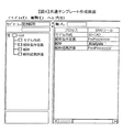
まず、S8では、テンプレート情報表示部によってデータを集める対象である共通テンプレートを入力する。テンプレート情報のキーワード入力画面の一例を図12に示す。ここでは、「定例解析」が入力されている。すると共通テンプレートに結び付けられたキーワードが、キーワード一覧に表示される。次にデータを集める差分テンプレートを決定するために、収集すべき差分テンプレートに結び付けられたキーワードを選択する。ここでは、「部品A」、「G1」を入力する。
【0047】
S9では、入力された共通テンプレートデータ、選択されたキーワードに結びついた差分テンプレートを共通テンプレートデータベース、差分テンプレートデータベースから検索し、データを読み込む。このとき、図11で示したようにキーワードデータベースを利用することにより、差分テンプレートの名称が分かるので、差分テンプレートのデータを集めることは可能である。
【0048】
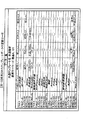
S10では、集められた解析情報を表示する。表示画面の一例を図13に示す。共通テンプレート名「定例解析」、選択キーワード「部品A」、「G1」が表示されている。すなわち、共通テンプレート「定例解析」を参照して解析作業を行ったもので、差分テンプレートにキーワード「部品A」、「G1」を定義した解析データ一覧が表示されている。表の一列目は、単位プロセスに定義された情報が記述され、「プロセス」、「ENGツール」、「入力ファイル」、「出力ファイル」、「参照ファイル」、「参照プログラム」が一つのセットとして、テンプレートで定義された4つの単位プロセスが表示されている。2列目は共通テンプレートで定義されたデータが表示されている。ここで、「/」は共通テンプレートとして定義されておらず、データが無いか、差分テンプレートにデータがあることを意味する。3列目から6列目に、共通テンプレート「定例解析」、キーワードに「部品A」、「G1」を持つ差分テンプレートの情報が示されている。図では、「部品A_1」、「部品A_2」、「部品A_3」、「部品A_4」の4個の差分テンプレートがあり、4回パラメータサーベイを行ったことを意味する。表中の「―」は、共通テンプレートのデータを引用することを意味する。すなわち「部品A_1」を例に取ると、プロセス名、ENGツールは共通テンプレートに記述された情報を利用するが、入力ファイルは、「部品A1」を利用することを意味する。また、参照ファイルとして「部品情報A」が定義され、参照するためのプログラムに「エディタ」を利用することになっている。また、共通テンプレートの参照ファイルに「作成方法」、参照プログラムに「Webブラウザ」が定義されているが、「部品A_1」から「部品A_4」全てにおいて、テンプレート実行部において、それらの情報の参照が可能であることを意味する。このように、フェーズF3によってパラメータサーベイによる解析情報を、キーワードによって収集が可能であり、一覧表示することによって、解析状況が一目で分かるようになっている。また、共通テンプレートに結び付けられたキーワードから、差分テンプレートに結ぶキーワードを選択することによって、差分テンプレートのグループ分けも出来る。これは、図11に示す、キーワードのデータ構造の一例が示すように、「部品A」、「G1」を持つ差分テンプレートのグループと、「部品A」、「太郎」を持つ差分テンプレートを持つグループに分けることが可能である。
【0049】
なお、上記実施例では、作業支援装置として説明したが、共通テンプレート作成部101、共通キーワード設定部102、テンプレート実行部103、差分テンプレート作成部104、差分キーワード設定部105、テンプレート情報表示部106のプログラムをCD−ROM、DVD−ROM等の記憶媒体に記憶させて、作業支援装置用ソフトウエアとして販売することができる。このときデータベースは、そのソフトウエアをインストールするコンピュータに接続された若しくは付随したハードディスクを自動的に領域化するプログラムを各部に備えることで生成される。
【0050】
本実施例によれば、差分テンプレートファイルが分散して保存されていても、キーワードデータベースに差分テンプレートの名称と共に場所が記述されているので、テンプレートファイルのデータを収集することが可能となる。
【0051】
また、図13に示された表が表示されるので、プログラムの実行やノウハウデータを参照することが容易となる。
【0052】
また、ネットワークでデータベースやサーバーを接続することで、テンプレート実行部を複数の操作者が別々の場所で行うことが可能となる。
【0053】
また、最適化エンジンを用いて、繰り返し解析部分を最適化計算により自動化することができる。この場合、パラメータ毎に差分テンプレートを生成する必要がある。
【0054】
また、繰り返し解析ばかりでなく、単一解析でも本実施例に係る装置を利用することができる。このとき、フェーズF2を1回のみ実行する場合と同等になる。
【0055】
また、解析手順や解析に必要なプログラム、ノウハウデータを共通テンプレートとして情報提供企業のサーバに登録し、この企業以外の会社が、インターネットを介して利用するビジネスモデルを構築することができる。
【0056】
以上、本実施例によれば、テンプレートに共通部分と非共通部分とに分けたため、複数の解析を行う場合のテンプレートの新規作成やコピーが必要なくなる。また、共通テンプレートのデータを更新すると、差分テンプレートに直ちに情報が反映されるため、変更に伴う作業工程の低減が可能となる。また、共通テンプレートと差分テンプレートとを、テンプレートと独立なキーワードで結び付けることで、テンプレート情報の収集を可能にし、かつ差分テンプレートのグループ分けが可能となる。
【0057】
以上、本実施例では、繰り返し解析を行なう解析作業に関して説明したが、コンピュータを用いた複数のプロセスが時系列(前段のプロセスによって得られた結果を後段のプロセスで用いて結果を得る)に存在し、その作業工程が汎用性を有する作業(特殊な作業であってもその作業に携わる者のうちで汎化される作業)であれば如何なる作業にも適用可能である。
【0058】
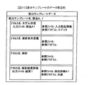
例えば、旅行会社における旅行プランの企画業務に用いることができる。プロセスは、大雑把な旅行プランを入力するプロセス、この旅行プランに基づいて、各種データベースを用いて行く先々の見所などを検索することでこの旅行プランを肉付けするプロセス、ルート検索システム、時間検索システムを利用して旅行日程を生成するプロセス、運賃計算システムやバス会社の費用データベースを用いて費用を計算するプロセス、最終的に日程と費用や行き先の写真等を貼り付けてパンフレットを作成するプロセスがある。
【0059】
操作者は、旅行プラン作成共有テンプレートを開いて、自分が企画した旅行プランの素案を入力する。そして各種データベースを開いて、各地の見所などの写真や説明を登録しておく。次に、旅行日程をルート検索や地点間必要移動時間を検索することで、旅行する順番を入れ替えるなどして決める。そして、この決めた旅行プランでかかる費用を計算し、もしこれが、企画として成立するようであれば、パンフレット生成プロセスで、パンフレットを作成する。そして、企画として成立しないと判断した場合、この旅行プランを差分テンプレートとして登録し、次のプランの検討に入る。次のプランが先のプランに似ている場合は、先の差分テンプレートを開き、共通テンプレートに入れることで新規作成することなく次の企画つくりを行なうことができる。そして、この旅行プランを差分テンプレートとしてデータベースに登録することで、他の企画者などが参照することで、先にその企画を作成した企画者のノウハウを活かせることができる。もちろん、企画として成立しないと判断した旅行プランの差分テンプレートには、なぜ成立しないと判断したかを記入しておくことで、次の判断時に解消されていれば再び旅行プランとして採用することができる。
【0060】
このように、コンピュータ上で行なう一連の作業が順番で流れ、その作業工程上で各種データベースやプログラムを参照し、最終生成物、上記実施例では部品Aの最適形状、上記旅行会社の例では企画として成立する旅行プラン、を得るために複数回作業を事項するものにおいて、ノウハウの蓄積と利用を行ないつつ最終生成物を得ることができる。
【0061】
【発明の効果】
本発明によれば、コンピュータを用いた作業を支援する支援装置を提供することができる。
【図面の簡単な説明】
【図1】本発明装置の全体構成図である。
【図2】本発明の利用手順を示す図である。
【図3】部品Aの解析作業を示す図である。
【図4】共通テンプレートの作成画面の一例を示す図である。
【図5】共通テンプレートを結ぶキーワードの入力画面の一例を示す図である。
【図6】共通テンプレートのデータ構造の一例を示す図である。
【図7】キーワードのデータ構造の一例を示す図である。
【図8】解析作業実施の一例を示す図である。
【図9】共通・差分テンプレートを結ぶキーワードの入力画面の一例を示す図である。
【図10】差分データのデータ構造の一例を示す図である。
【図11】キーワードの構造の一例を示す図である。
【図12】収集するテンプレート情報のキーワードの入力画面の一例を示す図である。
【図13】収集されたテンプレートデータの画面の一例を示す図である。
【符号の説明】
101…共通テンプレート作成部、102…共通キーワード設定部、103…テンプレート実行部、104…差分テンプレート作成部、105…差分キーワード設定部、106…テンプレート情報表示部、107…共通テンプレートデータベース、108…差分テンプレートデータベース、109…キーワードデータベース、110…計算機。[0001]
BACKGROUND OF THE INVENTION
The present invention relates to a work system using a computer.
[0002]
[Prior art]
In general, analysis work using CAE (Computer Aided Engineering) is a series of operations such as creation of shape models to be analyzed, creation of analysis meshes, definition of analysis conditions, analysis execution, and visualization and evaluation of analysis results. This is done by sequentially executing each program. Normally, when CAE is used for actual design work, the above-mentioned analysis work is not performed only once, but the shape model is changed in various ways, and a parameter survey that repeats many analyzes is performed. The ones that satisfy the design specifications are extracted.
[0003]
Conventionally, a technique described in Japanese Patent Laid-Open No. 2001-147950 has been known as a technique for supporting such repeated analysis work. That is, CAE shape data for analysis is created based on CAD data, analysis is performed based on the shape data, and the analysis result is determined. At this time, if the strength or the like is not satisfactory, the CAE shape data is changed and the analysis is performed again, and a series of analysis operations are executed until the satisfaction is satisfied. The CAE shape data is changed by an analysis engineer. If it is determined that a satisfactory CAE shape has been obtained, the CAD data is corrected based on the CAE shape.
[0004]
[Problems to be solved by the invention]
As described above, the analysis work includes a process of generating an analysis shape model, creating an analysis mesh model obtained by cutting a mesh from the shape model, and executing the analysis. At this time, since the strength or the like is not satisfied, when the model shape is changed, the location where the model shape is changed, the mesh tension, and various parameters that change slightly with the change are different for each analysis.
[0005]
In the above prior art, the change of the shape and the various changes accompanying it were left to the analysis engineer, and thus had the following problems.
[0006]
In the execution of a parameter survey that performs repetitive calculations, analysis is performed by changing input data such as shape data and analysis conditions many times. At this time, if the calculation conditions are different, the input / output files required for the analysis program are also different. Since the final CAD data is finally presented with the conditions such as strength matched, the analysis result accompanying the change of the shape data and the data in the middle of the calculation are not saved, and the change of the shape contributes to the analysis result. I did not know the degree. For this reason, when trying to analyze the contribution of this repeated shape change, analysis data must be created or copied for each analysis event of the parameter survey, and the analysis when the dimensions of the analysis target model are changed As shown in the results, there are a lot of similar analysis data highly related to each other. As a result, there is a problem that management of analysis data becomes difficult.
[0007]
Furthermore, model shape changes, analysis mesh cutting methods, subtle changes in analysis conditions, etc. are based on the know-how of the analysis engineer, so that the same result cannot be obtained if the analysis engineer changes. .
[0008]
An object of the present invention is to provide a support device that supports work using a computer.
[0009]
[Means for Solving the Problems]
In order to achieve the above object, the present invention provides an analysis procedure as information necessary for analysis in a work support apparatus that manages and classifies analysis result data and know-how data necessary for analysis procedure guidance and analysis using a computer. A common template creation unit that creates a common template that defines programs and input / output files, know-how information files and their reference programs required for analysis, and analysis results and evaluation results as information other than those defined in the common template. A difference template creation unit that creates a defined difference template, a common keyword setting unit that inputs a keyword that links the common template to another template or file, and a difference keyword setting that selects a keyword to be linked to the difference template from the keyword Part and said A template information display unit that displays a list of the other templates and the difference templates linked to a word, and when performing a parameter survey using the common template, information necessary for the analysis and analysis results And evaluation results are collected by the keyword and displayed in a list.
[0015]
DETAILED DESCRIPTION OF THE INVENTION
The present invention relates to a digital engineering utilization technique represented by CAE (Computer Aided Engineering) that smoothly performs design work and a method thereof, and particularly in an analysis work for a parameter survey that requires a plurality of analysis executions. The present invention relates to an analysis work support apparatus and method for efficiently managing and classifying know-how data necessary for analysis procedure guidance and analysis and analysis result data. Hereinafter, this embodiment will be described in detail.
[0016]
FIG. 1 is a block diagram showing a system configuration of an embodiment of an analysis work support apparatus according to the present invention. 1 includes a common
[0017]
The common
[0018]
The common
[0019]
The
[0020]
The difference
[0021]
In other words, a common template is a description of data that is commonly used by everyone, such as analysis procedures and programs required for analysis when performing repeated analysis. Define non-common parts as difference templates for common data such as user findings.
[0022]
The difference
[0023]
The template
[0024]
In the
[0025]
The
[0026]
The
[0027]
The
[0028]
The processing procedure of the embodiment configured as described above will be described with reference to FIGS. FIG. 2 is a flowchart showing a use procedure in the analysis work support apparatus shown in FIG. The usage procedure in the present embodiment is roughly divided into three phases.
[0029]
First, a routine analysis procedure is created as a common template. At this time, an analysis procedure, information necessary for analysis, such as a program and input / output file necessary for analysis, a know-how information file and its reference program are defined. Then define keywords that are tied to the common template. This is designated as phase F1.
[0030]
Second, analysis is performed using a common template. In this operation, the program is executed according to the common analysis template, and analysis work is performed while referring to know-how information. Information other than the information defined in the common template such as analysis results and evaluation results is defined as a difference template. At this time, in order to link the common template and the difference template, a keyword is selected from the keywords linked to the common template. This is designated as phase F2. The phase F2 is a phase in which the analysis target and the analysis procedure are the same, but the analysis is repeatedly performed by changing the dimensions of the analysis target model for the parameter survey.
[0031]
Finally, information added to the template is collected and displayed using keywords associated with the common template and the difference template. This is designated as phase F3.
[0032]
Here, taking the analysis work of the part A shown in FIG. 3 as an example, execution of the analysis work using this embodiment will be described.
[0033]
In phase F1, first, a common template is created by the common template creation unit as S1. FIG. 4 shows an example of a common template creation screen. Here, a typical analysis work regularly performed on the part A is defined. As shown in the figure, “model creation” → “analysis condition definition” → “analysis” → “analysis result evaluation” is defined as an analysis procedure, and programs “3D-CAD”, “PreProcessor”, The rejection template creator defines “Analysis” and “PostProcessor”. In the common template, input / output files necessary for analysis, know-how reference information, and reference programs thereof can be defined. For example, in the model creation folder, information on the predecessor regarding the specific use of “PreProcessor” (know-how), for example, a convenient function when creating a model for analysis by placing a mesh on the model, or a case of failure By recording the file in which is written, you can expand the technique of use to other users. Here, this common template is named “regular analysis”.
[0034]
Next, keywords to be linked to the common template in S2 are defined in the common keyword setting unit. FIG. 5 shows an example of the keyword input screen. “Regular analysis” defined in S1 is displayed as the common template name linked to the keyword. Also, as a keyword input, the keyword “Taro” is currently being input, and “Taro” is registered as a keyword when the add button is pressed. The registered keywords are displayed in the keyword list, and “part A” and “G1” are currently registered. Further, the keyword can be deleted by using the delete button.
[0035]
In S2, the three keywords “part A”, “G1”, and “Taro” are linked to the common template “regular analysis”.
[0036]
In S3, the common template and keyword defined in S1 and S2 are registered in the common template database and the keyword database, respectively. FIG. 6 shows an example of a common template data structure, and FIG. 7 shows an example of a keyword data structure. As a data structure of the common template, a common template name, a process name of the procedure, a program used by the process and its input / output file, a reference file such as know-how necessary for analysis, and the program are described. Here, “process”, “ENG tool”, “input file”, “output file”, “reference file”, and “reference program” are defined as one unit process. That is, “model creation” is defined as one unit process, and programs and files necessary for performing work are defined. A blank part in the unit process, that is, an input file of the process name “model creation” is a part defined in S4 of the phase F2, and is an item defined in the difference template. In addition, the portion where the data is described means that the data is used in the common template. If data is not used, the data in the unit process may be empty. Here, the content of the unit process is “process”, “ENG tool”, “input file”, “output file”, “reference file”, “reference program”, but there is no data restriction, and the unit process can be defined There is no restriction on the number of items. Next, the process order is described in the procedure definition. This is equivalent to the work procedure. Next, as a keyword data structure, a common template name and a keyword associated with the common template are described. This is defined in S2. The difference template name and its keyword will be described in S7. In this way, common templates and keywords are defined in phase F1.
[0037]
In phase F2, as S4, the common template is read and analyzed by the template execution unit. Here, as shown in FIG. 8, work is performed using defined programs and input / output files according to the analysis procedure described in the common template “regular analysis”. The figure is an example showing that “analysis condition definition” is in progress, and the analysis condition is defined for the input file “3DOut” (see FIG. 6). In this way, a series of analysis operations are performed according to the contents described in the read common template.
[0038]
Data newly generated for each analysis, such as analysis results and evaluations that are blank in the common template data, is defined in S4. In other words, when new information (data, reference file) that is not described in the common template is added, the contents added for each process in the template as knowledge specific to this analysis among the analyzes executed multiple times And the calculation result in the process is registered for each process. As a result, the selection of the data performed by the operator for performing this analysis, the reference file and program, and the calculation result obtained are recorded in the order of the process for each analysis. For this reason, the knowledge of the operator who performed this analysis is recorded during this analysis. Therefore, since knowledge is accumulated for each analysis and for each process, for example, when the analysis is performed after changing the dimension of the part A shown in FIG. Knowledge such as how to change the mesh, selection of conditions, etc. is accumulated, and it is possible to easily clarify the causal relationship between the dimensional change of the part and the analysis result, and when other analysis engineers perform analysis, the knowledge Can be used, so that the work efficiency is improved.
[0039]
In the above embodiment, the work is advanced by selecting a common template as an input of the template execution unit. However, a difference template that has already been created may be read and executed. In this case, since the content of the common template is not recorded in the difference template, it is necessary to read information on the common template referred to by the difference template in addition to the difference template.
[0040]
In step S5, a difference template for this analysis work is created. As shown in FIG. 10, the difference template name is “part A_1”. The reason for “A_1” is that the analysis is performed a plurality of times even for the same part. The difference
[0041]
Next, keywords to be linked to the common / difference template in S6 are defined. FIG. 9 shows an example of the keyword input screen. The common template name is “regular analysis”, and keywords associated with the common template are displayed in the keyword list. A keyword connecting “component A_1” and “regular analysis” is selected from the keyword list. Here, “component A” and “G1” are selected. In this way, the analysis operation “part A_1” is connected to the common analysis template “regular analysis” by the keywords “part A” and “G1”.
[0042]
In S7, the difference template and the keyword are stored in the difference template database and the keyword database. FIG. 10 shows the data structure of the difference template. Here, the difference template name, process name, and information thereof are described. The reason why the process information is small is that information other than that defined in the common template is described in the difference template. That is, programs necessary for analysis, know-how information commonly used, intermediate data, and the like are defined by a common template, and input data and analysis results necessary for analysis are stored as a difference template. The analysis procedure is usually regarded as common data and is not described in the difference template. However, if there is an analysis procedure unique to the analysis operator, a process added or inserted in addition to the common template is described in the difference template.
[0043]
FIG. 11 shows the data structure of the keyword. Although it is equivalent to FIG. 7, “part A_1” defined in S5 is described in the difference template name, and “part A” and “G1” defined in S6 are described in the keyword. Here, a plurality of pieces of difference template information are described on the assumption that the analysis work of phase F2 is repeated.
[0044]
As described above, the phase F2 is an analysis work phase. In normal design, a parameter survey is performed in which the shape and physical property values to be analyzed are changed in various ways and analyzed. At this time, analysis procedures, programs, intermediate file names, know-how data, and the like are not changed for each repeated calculation. Therefore, common work parts, intermediate files, know-how, etc. in repetitive calculations are defined as common templates, and the common templates of corresponding analysis work are repeatedly analyzed in the template execution unit. For repeated calculations, non-common parts such as shape-changed data and analysis results are defined as difference templates. This eliminates the need to create or copy a template for each repeated calculation. If the common template is changed, the information is immediately reflected in the difference template that refers to the common template. In the case of repeated calculation in this way, phase 2 is repeated and only the difference template is created.
[0045]
The phase F3 will be described. When the analysis process is repeatedly performed using the common template, there are a plurality of difference templates. Taking a parameter survey related to part A as an example, common analysis data of part A is a common template, and a plurality of data such as analysis results obtained by changing the shape and physical property values of part A exist as difference templates. At this time, the common template and the difference template have a relationship of the common analysis data of the part A, the analysis input file, and the analysis result through the keyword. Here, a summary of a plurality of analysis results related to the part A, that is, data defined in the difference template will be described.
[0046]
First, in S8, a common template which is a target for collecting data is input by the template information display unit. An example of a template information keyword input screen is shown in FIG. Here, “regular analysis” is input. Then, keywords associated with the common template are displayed in the keyword list. Next, in order to determine a difference template for collecting data, a keyword associated with the difference template to be collected is selected. Here, “component A” and “G1” are input.
[0047]
In S9, the input common template data and the difference template linked to the selected keyword are searched from the common template database and the difference template database, and the data is read. At this time, as shown in FIG. 11, by using the keyword database, the name of the difference template is known, so that the data of the difference template can be collected.
[0048]
In S10, the collected analysis information is displayed. An example of the display screen is shown in FIG. The common template name “regular analysis” and the selection keywords “part A” and “G1” are displayed. That is, the analysis work is performed with reference to the common template “regular analysis”, and an analysis data list in which the keywords “part A” and “G1” are defined in the difference template is displayed. In the first column of the table, information defined in the unit process is described, and “process”, “ENG tool”, “input file”, “output file”, “reference file”, “reference program” are set as one set. The four unit processes defined in the template are displayed. The second column displays data defined by the common template. Here, “/” means that there is no data defined in the common template and there is no data, or there is data in the difference template. In the third column to the sixth column, information of the difference template having the common template “regular analysis” and the keywords “part A” and “G1” is shown. In the figure, there are four difference templates “part A_1”, “part A_2”, “part A_3”, and “part A_4”, which means that the parameter survey has been performed four times. “-” In the table means to quote the data of the common template. In other words, taking “part A_1” as an example, the process name and the ENG tool use information described in the common template, but the input file means that “part A1” is used. In addition, “component information A” is defined as a reference file, and an “editor” is used as a program for reference. In addition, “creating method” is defined in the reference file of the common template, and “Web browser” is defined in the reference program. It means that it is possible. As described above, the analysis information by the parameter survey can be collected by the keyword in the phase F3, and the analysis status can be understood at a glance by displaying the list. Moreover, the difference templates can be grouped by selecting the keyword to be connected to the difference template from the keywords connected to the common template. As shown in the example of the keyword data structure shown in FIG. 11, this is a group of difference templates having “part A” and “G1” and a group having difference templates having “part A” and “Taro”. It can be divided into
[0049]
In the above embodiment, the work support apparatus has been described. However, the common
[0050]
According to the present embodiment, even if the difference template file is distributed and stored, the location of the difference template file and the name of the difference template are described in the keyword database, so that the template file data can be collected.
[0051]
Also, since the table shown in FIG. 13 is displayed, it is easy to execute the program and refer to know-how data.
[0052]
In addition, by connecting a database or a server via a network, a template execution unit can be performed by a plurality of operators at different locations.
[0053]
In addition, it is possible to automate the repeated analysis portion by optimization calculation using the optimization engine. In this case, it is necessary to generate a difference template for each parameter.
[0054]
Further, the apparatus according to the present embodiment can be used not only for repetitive analysis but also for single analysis. At this time, this is equivalent to the case where the phase F2 is executed only once.
[0055]
In addition, analysis procedures, programs necessary for analysis, and know-how data can be registered as a common template in the server of the information providing company, and a business model used by companies other than this company via the Internet can be constructed.
[0056]
As described above, according to the present embodiment, since the template is divided into the common part and the non-common part, it is not necessary to newly create or copy a template when performing a plurality of analyses. Further, when the data of the common template is updated, the information is immediately reflected in the difference template, so that it is possible to reduce the work process accompanying the change. Further, by connecting the common template and the difference template with a keyword independent of the template, it is possible to collect template information and group the difference templates.
[0057]
As described above, in this embodiment, the analysis work for performing repetitive analysis has been described. However, a plurality of processes using a computer exist in time series (results obtained by the previous process are used in the subsequent process to obtain the results). However, the present invention can be applied to any work as long as the work process is versatile (a work that is generalized among those involved in the work even if it is a special work).
[0058]
For example, it can be used for a travel plan planning business in a travel agency. The process includes a process for inputting a rough travel plan, a process for fleshing out this travel plan by searching for various points of interest using various databases based on this travel plan, a route search system, and a time search system. There is a process to generate travel dates by using it, a process to calculate costs using a fare calculation system or a cost database of a bus company, and finally a process to create a pamphlet by pasting schedules and costs, photos of destinations, etc. .
[0059]
The operator opens the travel plan creation shared template and inputs a draft of the travel plan planned by the operator. Open various databases and register photos and explanations of local attractions. Next, the travel schedule is determined by searching the route or searching for the necessary travel time between points, for example, by changing the order of travel. Then, the cost required for the determined travel plan is calculated, and if this is approved as a plan, a pamphlet is created by the pamphlet generation process. If it is determined that the plan is not established, the travel plan is registered as a difference template, and the next plan is considered. If the next plan is similar to the previous plan, the next plan can be created without creating a new template by opening the previous difference template and putting it in the common template. Then, by registering this travel plan in the database as a difference template, other planners can refer to the plan so that the know-how of the planner who previously created the plan can be utilized. Of course, by filling in the difference template of the travel plan that is determined not to be established as a plan, it is possible to adopt it as a travel plan again if it is resolved at the next determination by entering the reason why it is determined not to be satisfied. .
[0060]
In this way, a series of work performed on the computer flows in order, and various databases and programs are referred to in the work process, and the final product, the optimum shape of the part A in the above embodiment, the plan in the above travel company example In order to obtain a travel plan established as follows, the final product can be obtained while accumulating and using know-how.
[0061]
【The invention's effect】
ADVANTAGE OF THE INVENTION According to this invention, the assistance apparatus which assists the operation | work using a computer can be provided.
[Brief description of the drawings]
FIG. 1 is an overall configuration diagram of an apparatus according to the present invention.
FIG. 2 is a diagram showing a use procedure of the present invention.
FIG. 3 is a diagram illustrating an analysis operation of a part A.
FIG. 4 is a diagram illustrating an example of a common template creation screen.
FIG. 5 is a diagram showing an example of a keyword input screen for connecting common templates.
FIG. 6 is a diagram illustrating an example of a data structure of a common template.
FIG. 7 is a diagram illustrating an example of a keyword data structure;
FIG. 8 is a diagram illustrating an example of performing analysis work.
FIG. 9 is a diagram showing an example of an input screen for keywords connecting common / difference templates.
FIG. 10 is a diagram illustrating an example of a data structure of difference data.
FIG. 11 is a diagram illustrating an example of a keyword structure.
FIG. 12 is a diagram showing an example of an input screen for keywords of template information to be collected.
FIG. 13 is a diagram showing an example of a screen of collected template data.
[Explanation of symbols]
DESCRIPTION OF
Claims (2)
解析に必要な情報として、解析手順、解析に必要なプログラムや入出力ファイル、ノウハウ情報ファイルやその参照プログラム、を定義した共通テンプレートを作成する共通テンプレート作成部と、
前記共通テンプレートに定義された以外の情報として解析結果や評価結果を定義した差分テンプレートを作成する差分テンプレート作成部と、
前記共通テンプレートと他のテンプレートやファイルとを結び付けるキーワードを入力する共通キーワード設定部と、
前記キーワードから前記差分テンプレートに結び付けるキーワードを選択する差分キーワード設定部と、
前記キーワードに結び付けられた前記他のテンプレート及び前記差分テンプレートの一覧を表示するテンプレート情報表示部と、
を備え、前記共通テンプレートを利用してパラメータサーベイを行う場合、前記解析に必要な情報と、解析結果や評価結果と、を前記キーワードによって収集し、一覧表示することを特徴とする作業支援装置。In the work support device that manages and classifies know-how data necessary for analysis procedure guidance and analysis and analysis result data using a computer ,
A common template creation unit that creates a common template that defines analysis procedures, programs and input / output files required for analysis, know-how information files and their reference programs as information required for analysis,
A difference template creation unit that creates a difference template that defines analysis results and evaluation results as information other than that defined in the common template;
A common keyword setting unit for inputting a keyword that links the common template to another template or file;
A difference keyword setting unit for selecting a keyword to be linked to the difference template from the keyword;
A template information display unit for displaying a list of the other template and the difference template linked to the keyword;
And when the parameter survey is performed using the common template, the information necessary for the analysis, the analysis result and the evaluation result are collected by the keyword and displayed in a list .
Priority Applications (2)
| Application Number | Priority Date | Filing Date | Title |
|---|---|---|---|
| JP2002222349A JP4069701B2 (en) | 2002-07-31 | 2002-07-31 | Work support device |
| US10/369,689 US6920364B2 (en) | 2002-07-31 | 2003-02-21 | Work assistance apparatus and memory medium for use therein |
Applications Claiming Priority (1)
| Application Number | Priority Date | Filing Date | Title |
|---|---|---|---|
| JP2002222349A JP4069701B2 (en) | 2002-07-31 | 2002-07-31 | Work support device |
Publications (2)
| Publication Number | Publication Date |
|---|---|
| JP2004062707A JP2004062707A (en) | 2004-02-26 |
| JP4069701B2 true JP4069701B2 (en) | 2008-04-02 |
Family
ID=31184922
Family Applications (1)
| Application Number | Title | Priority Date | Filing Date |
|---|---|---|---|
| JP2002222349A Expired - Fee Related JP4069701B2 (en) | 2002-07-31 | 2002-07-31 | Work support device |
Country Status (2)
| Country | Link |
|---|---|
| US (1) | US6920364B2 (en) |
| JP (1) | JP4069701B2 (en) |
Families Citing this family (11)
| Publication number | Priority date | Publication date | Assignee | Title |
|---|---|---|---|---|
| JP4032306B2 (en) * | 2003-04-01 | 2008-01-16 | 株式会社日立製作所 | Design work support device |
| US20050197936A1 (en) * | 2004-01-13 | 2005-09-08 | International Business Machines Corporation | Monte Carlo grid scheduling algorithm selection optimization |
| US7603253B2 (en) * | 2004-01-13 | 2009-10-13 | International Business Machines Corporation | Apparatus and method for automatically improving a set of initial return on investment calculator templates |
| JP2006058976A (en) * | 2004-08-17 | 2006-03-02 | Fujitsu Ltd | Optimization analysis apparatus, optimization analysis method and optimization analysis program |
| JP2006113934A (en) * | 2004-10-18 | 2006-04-27 | Hitachi Ltd | Program development support apparatus and method, and program |
| US20070094599A1 (en) * | 2005-09-08 | 2007-04-26 | Heidelberger Druckmaschinen Aktiengesellschaft | Method and system for training an operator of a paper folding machine |
| JP2007183700A (en) * | 2006-01-04 | 2007-07-19 | Hitachi Ltd | Shape model creation device |
| JP4850656B2 (en) * | 2006-10-25 | 2012-01-11 | 株式会社日立製作所 | Analysis work guidance apparatus, analysis work guidance method and program |
| US20120150632A1 (en) * | 2010-12-08 | 2012-06-14 | At&T Intellectual Property I, L.P. | Integrated customer premises equipment troubleshooting assistance |
| US10748092B2 (en) * | 2011-06-07 | 2020-08-18 | The Boeing Company | Systems and methods for creating intuitive context for analysis data |
| US10565110B2 (en) | 2016-08-02 | 2020-02-18 | Microsoft Technology Licensing, Llc | Reducing memory usage for long standing computations |
Family Cites Families (7)
| Publication number | Priority date | Publication date | Assignee | Title |
|---|---|---|---|---|
| US6606740B1 (en) * | 1998-10-05 | 2003-08-12 | American Management Systems, Inc. | Development framework for case and workflow systems |
| US6377956B1 (en) * | 1999-02-22 | 2002-04-23 | Siemens Corporate Research, Inc. | Automatically configuring product manual by binding document objects in logical structure to proper versions of component documents in a document database |
| JP2001147950A (en) | 1999-11-22 | 2001-05-29 | Toray Ind Inc | Method and device for preparing article form data |
| SE522958C2 (en) * | 2000-12-29 | 2004-03-16 | Nobel Biocare Ab | Procedure, arrangement (device) and programs at or for prosthetic installation |
| US20020196250A1 (en) * | 2001-06-20 | 2002-12-26 | Gateway, Inc. | Parts assembly for virtual representation and content creation |
| US7280948B2 (en) * | 2002-01-31 | 2007-10-09 | Delphi Technologies, Inc. | System and method for integrating geometric models |
| AU2003279994A1 (en) * | 2002-10-21 | 2004-05-13 | John P. Sinisi | System and method for mobile data collection |
-
2002
- 2002-07-31 JP JP2002222349A patent/JP4069701B2/en not_active Expired - Fee Related
-
2003
- 2003-02-21 US US10/369,689 patent/US6920364B2/en not_active Expired - Lifetime
Also Published As
| Publication number | Publication date |
|---|---|
| US20040024479A1 (en) | 2004-02-05 |
| JP2004062707A (en) | 2004-02-26 |
| US6920364B2 (en) | 2005-07-19 |
Similar Documents
| Publication | Publication Date | Title |
|---|---|---|
| CA1286406C (en) | Automated interface to project management tool | |
| US6240395B1 (en) | Device and method for project management | |
| US7058588B2 (en) | Dependency-based work flow integration and reduction | |
| US8560574B2 (en) | Apparatus and dependency structure matrix for assisting in optimization of a complex, hierarchical data structure | |
| US20100114355A1 (en) | Method and system for management of manufacturing information | |
| JP4069701B2 (en) | Work support device | |
| JP7055064B2 (en) | Database migration support system and program | |
| Siddharth et al. | A multiple-domain matrix support to capture rationale for engineering design changes | |
| Beier et al. | Supporting product development through cross-discipline dependency-modeling–novel approaches for traceability-usage | |
| Krenczyk et al. | Integration of scheduling and discrete event simulation systems to improve production flow planning | |
| JPH11265368A (en) | Working procedure management system | |
| JP4088760B2 (en) | Design work support device | |
| Zahedi et al. | Interaction with analysis and simulation methods via minimized computer-readable BIM-based communication protocol | |
| US6453318B1 (en) | Control apparatus of structured information and method of controlling the information | |
| JP2004310317A (en) | Business support device | |
| JP5144458B2 (en) | Created document navigation system | |
| JP4032306B2 (en) | Design work support device | |
| JPH08234977A (en) | Manifold progress management system for software project | |
| Listl et al. | An Architecture for Knowledge Graph based Simulation Support | |
| JP2002032225A (en) | Work result managing device, work plan support device and storage medium in which program to make computer perform processing by the same devices is stored | |
| JP3695410B2 (en) | Production technology management method and apparatus therefor | |
| Bordegoni et al. | A methodology for evaluating the adoption of Knowledge and Innovation Management tools in a product development process | |
| Herrmann | Visualization of release planning | |
| JP4088207B2 (en) | Bill of materials editing method and editing system | |
| JPH09292981A (en) | Device and method for supporting object-oriented system analysis and design |
Legal Events
| Date | Code | Title | Description |
|---|---|---|---|
| A621 | Written request for application examination |
Free format text: JAPANESE INTERMEDIATE CODE: A621 Effective date: 20050121 |
|
| RD01 | Notification of change of attorney |
Free format text: JAPANESE INTERMEDIATE CODE: A7421 Effective date: 20060419 |
|
| A131 | Notification of reasons for refusal |
Free format text: JAPANESE INTERMEDIATE CODE: A131 Effective date: 20070821 |
|
| A521 | Written amendment |
Free format text: JAPANESE INTERMEDIATE CODE: A523 Effective date: 20071011 |
|
| TRDD | Decision of grant or rejection written | ||
| A01 | Written decision to grant a patent or to grant a registration (utility model) |
Free format text: JAPANESE INTERMEDIATE CODE: A01 Effective date: 20071225 |
|
| A61 | First payment of annual fees (during grant procedure) |
Free format text: JAPANESE INTERMEDIATE CODE: A61 Effective date: 20080107 |
|
| R151 | Written notification of patent or utility model registration |
Ref document number: 4069701 Country of ref document: JP Free format text: JAPANESE INTERMEDIATE CODE: R151 |
|
| FPAY | Renewal fee payment (event date is renewal date of database) |
Free format text: PAYMENT UNTIL: 20110125 Year of fee payment: 3 |
|
| FPAY | Renewal fee payment (event date is renewal date of database) |
Free format text: PAYMENT UNTIL: 20110125 Year of fee payment: 3 |
|
| FPAY | Renewal fee payment (event date is renewal date of database) |
Free format text: PAYMENT UNTIL: 20120125 Year of fee payment: 4 |
|
| FPAY | Renewal fee payment (event date is renewal date of database) |
Free format text: PAYMENT UNTIL: 20130125 Year of fee payment: 5 |
|
| LAPS | Cancellation because of no payment of annual fees |